

Sanyo SAP-CMRV1924EH, SAP-CMRV2444EH, SAP-CMRV1934EH, SAP-CMRV3144EH, SAPKMRV74EH Technical & Service Manual
...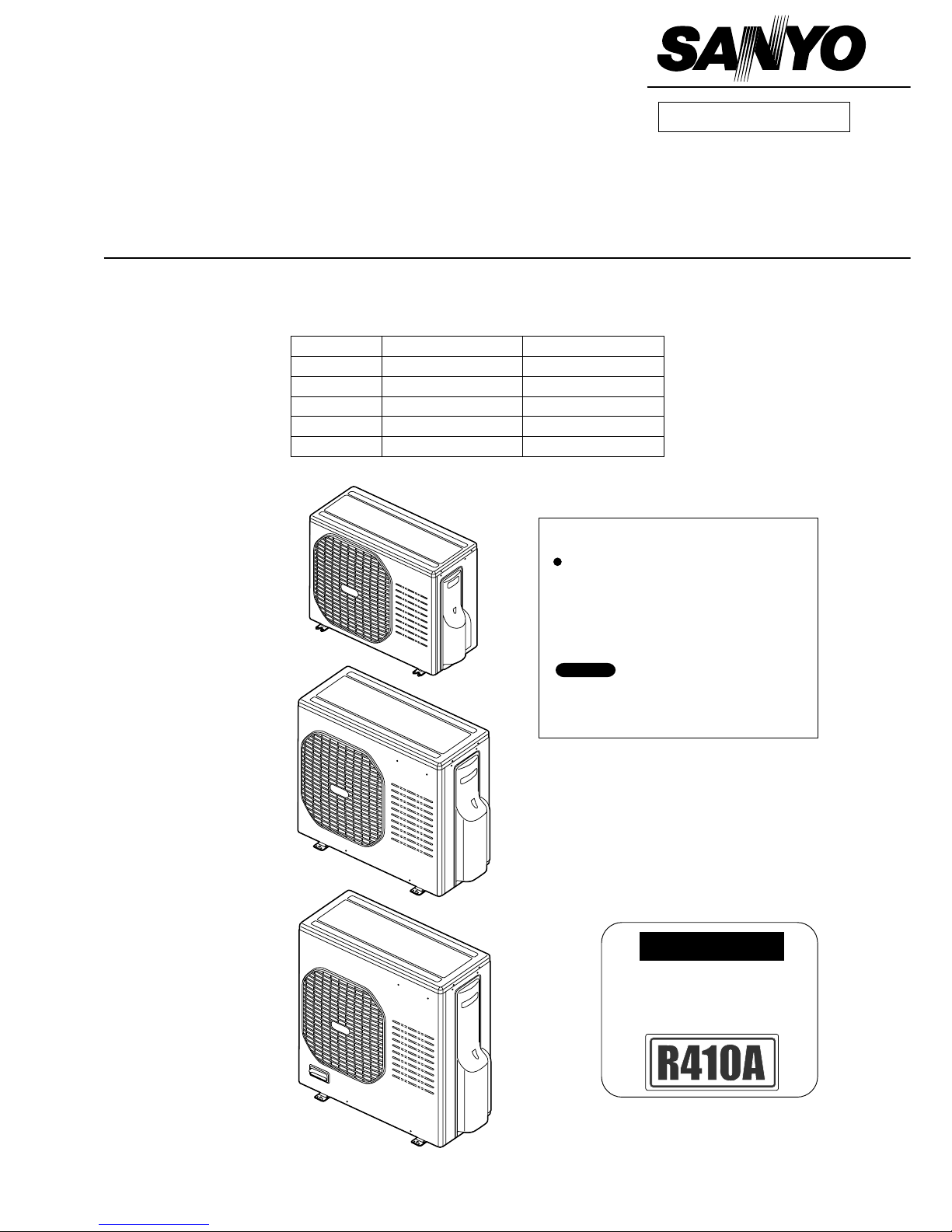
TECHNICAL & SERVICE MANUAL
OUTDOOR UNIT : SAP-CMRV1424EH
SAP-CMRV1924EH
SAP-CMRV1934EH
SAP-CMRV2444EH
SAP-CMRV3144EH
SAP-CMRV1424EH
SAP-CMRV1924EH
SAP-CMRV1934EH
SAP-CMRV2444EH
SAP-CMRV3144EH
DC INVERTER MULTI-SYSTEM AIR CONDITIONER
Outdoor Model No.
SAP-CMRV1424EH
SAP-CMRV1924EH
SAP-CMRV1934EH
SAP-CMRV2444EH
SAP-CMRV3144EH
Capacity
4.0kW
5.6kW
5.6kW
6.8kW
8.0kW
Product Code No.
1 852 330 12
1 852 336 59
1 852 330 13
1 852 330 14
1 852 330 15
FILE NO.
REFERENCE NO. SM700662
< Applicable Indoor Units >
Wall mounted type
For details about the combination, refer to
"Unit Combination Table" in the Appendix of
this manual.
SAP-KMRV74EH
SAP-KMRV94EH
SAP-KMRV124EH
SAP-KRV184EH
SAP-KRV244EH
NOTE
IMPORTANT
These air conditioners employ new
refrigerant R410A.
Pay special attention when
servicing the unit.
Destination: Europe
Northern Europe
When Wiring
ELECTRICAL SHOCK CAN CAUSE
SEVERE PERSONAL INJURY OR DEATH.
ONLY A QUALIFIED, EXPERIENCED
ELECTRICIAN SHOULD ATTEMPT TO
WIRE THIS SYSTEM.
SPECIAL PRECAUTIONS
This symbol refers to a hazard
or unsafe practice which can
result in severe personal
injury or death.
This symbol refers to a hazard
or unsafe practice which can
result in personal injury or
product or property damage.
CAUTION
CAUTION
WARNING
WARNING
Important!
Please Read Before Starting
This air conditioning system meets strict safety and
operating standards. As the installer or service person, it
is an important part of your job to install or service the
system so it operates safely and efficiently.
For safe installation and trouble-free operation, you
must:
Carefully read this instruction booklet before beginning.
Follow each installation or repair step exactly as shown.
Observe all local, state, and national electrical codes.
Pay close attention to all warning and caution notices
given in this manual.
If Necessary, Get Help
These instructions are all you need for most installation
sites and maintenance conditions. If you require help for
a special problem, contact our sales/service outlet or
your certified dealer for additional instructions.
In Case of Improper Installation
The manufacturer shall in no way be responsible for
improper installation or maintenance service, including
failure to follow the instructions in this document.
Do not supply power to the unit until all wiring and
tubing are completed or reconnected and checked.
Highly dangerous electrical voltages are used in this
system. Carefully refer to the wiring diagram and these
instructions when wiring. Improper connections and
inadequate grounding can cause accidental injury or
death.
Ground the unit following local electrical codes.
Connect all wiring tightly. Loose wiring may cause
overheating at connection points and a possible fire
hazard.
When Transporting
Be careful when picking up and moving the indoor and
outdoor units. Get a partner to help, and bend your knees
when lifting to reduce strain on your back. Sharp edges or
thin aluminum fins on the air conditioner can cut your
fingers.
When Installing
In a Ceiling or Wall
Make sure the ceiling/wall is strong enough to hold the
unit’s weight. It may be necessary to construct a strong
wood or metal frame to provide added support.
In a Room
Properly insulate any tubing run inside a room to prevent
"sweating" that can cause dripping and water damage to
walls and floors.
In Moist or Uneven Locations
Use a raised concrete pad or concrete blocks to provide a
solid, level foundation for the outdoor unit. This prevents
water damage and abnormal vibration.
In an Area with High Winds
Securely anchor the outdoor unit down with bolts and a
metal frame. Provide a suitable air baffle.
In a Snowy Area (for Heat Pump-type Systems)
Install the outdoor unit on a raised platform that is higher
than drifting snow. Provide snow vents.
When Connecting Refrigerant Tubing
Use the flare method for connecting tubing.
Apply refrigerant lubricant to the matching surfaces of
the flare and union tubes before connecting them, then
tighten the nut with a torque wrench for a leak-free
connection.
Check carefully for leaks before starting the test run.
When Servicing
Tu rn the power off at the main power box (mains) before
opening the unit to check or repair electrical parts and
wiring.
Keep your fingers and clothing away from any moving
parts.
Clean up the site after you finish, remembering to check
that no metal scraps or bits of wiring have been left
inside the unit being serviced.
Others
Ventilate any enclosed areas when installing or testing
the refrigeration system. Escaped refrigerant gas, on
contact with fire or heat, can produce dangerously toxic
gas.
Confirm upon completing installation that no refrigerant
gas is leaking. If escaped gas comes in contact with a
stove, gas water heater, electric room heater or other
heat source, it can produce dangerously toxic gas.
•
•
•
•
•
•
•
•
•
•
•
•
2

Table of Contents
APPLICABLE INDOOR UNIT
1. OPERATING RANGE
2. SPECIFICATIONS
2-1. Unit Specifications
2-2. Major Component Specifications
2-3. Other Component Specifications
3. DIMENSIONAL DATA
4. REFRIGERANT FLOW DIAGRAM
4-1. Refrigerant Flow Diagram
5. PERFORMANCE DATA
5-1. Temperature Charts
5-2. Heating Performance
6. ELECTRICAL DATA
6-1. Electric Wiring Diagrams
7. FUNCTIONS
7-1. Explanation of Functions
7-2. Protective Functions
8. TROURLE SHOOTING
8-1. Precautions before Performing Inspection or Repair
8-2. Trouble Diagnosis by Error Monitor Lamps
8-3. Checking the Outdoor System
8-4. Trouble Diagnosis of Each Part
8-5. Trouble Diagnosis of Fan Motor
9. REFRIGERANT R410A:
SPECIAL PRECAUTIONS WHEN SERVICING UNIT
9-1. Characteristics of New Refrigerant R410A
9-2. Checklist before Servicing
9-3. Tools Specifically for R410A
9-4. Tubing Installation Procedures
9-5. In Case of Compressor Malfunction
9-6. In Case Refrigerant is Leaking
9-7. Charging Additional Refrigerant
9-8. Retro-Fitting Existing Systems
5
6
7
12
17
18
23
28
28
29
34
38
41
42
43
44
47
48
48
50
50
51
53
54
54
.......................................................................................................
...................................................................................................................
.............................................................................................................
.......................................................................................
.......................................................................................
.....................................................................................................................
...................................................................................................
............................................................................................................
..........................................................................................................
....................................................................................................
....................................................................................................
...........................................................................................................
...........................................................
.........................................................................
............................................................................................
..........................................................................................
..........................................................................................
.........................................................................
...................................................................................................
................................................................................................
............................................................................................
....................................................................................
............................................................................................
..........................................................................................
............................................................................................
Page
3

APPENDIX A INSTALLATION INSTRUCTIONS
(SAP-CMRV1424EH)
APPENDIX B INSTALLATION INSTRUCTIONS
SAP-CMRV1924EH, SAP-CMRV1934EH
SAP-CMRV2444EH, SAP-CMRV3144EH
APPENDIX C UNIT COMBINATION TABLES
A-1
A-2
A-3
.............................................................................
.............................................................................
.................................................................................
Page
()
4
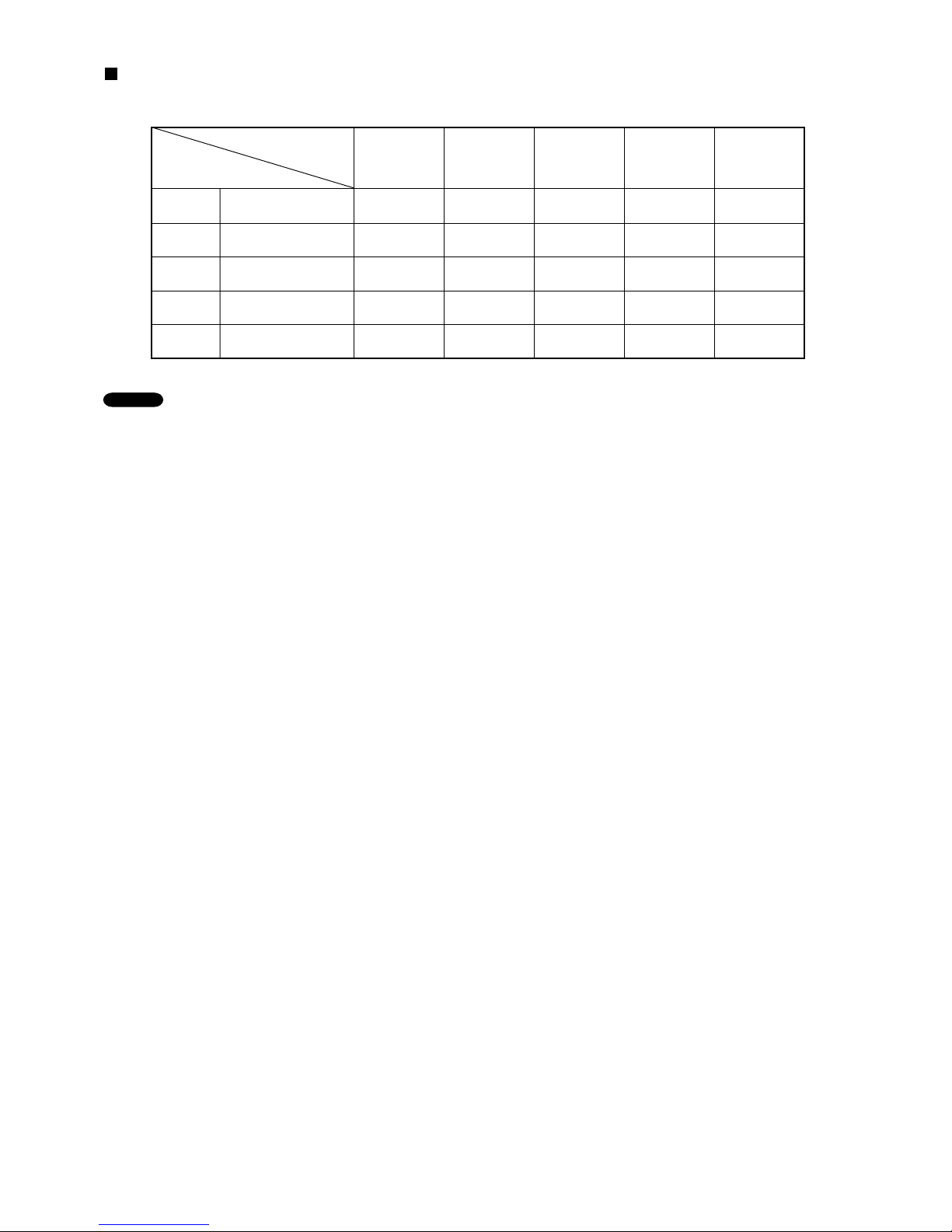
APPLICABLE INDOOR UNITS
SAP-CMRV1424EH
Multi-Outdoor Unit
Indoor Unit
YES YES YES NO NO
SAP-CMRV1924EH YES YES YES YES NO
SAP-CMRV1934EH YES YES YES YES NO
SAP-CMRV2444EH YES YES YES YES YES
SAP-CMRV3144EH
2-Room
2-Room
3-Room
4-Room
4-Room YES YES YES YES YES
SAPKMRV74EH
SAPKMRV94EH
SAPKMRV124EH
SAPKRV184EH
SAPKRV244EH
NOTE
1. The table lists the wall-mounted type of indoor units as representative models.
2. For details on the applicable indoor units other than the wall-mounted type, refer to the catalog.
5

1. OPERATING RANGE
Maximum
Minimum
Maximum
Minimum
32 °C D.B. / 23 °C W.B.
19 °C D.B. / 14 °C W.B.
27 °C D.B.
16 °C D.B.
43 °C D.B.
19 °C D.B.
24 °C D.B. / 18 °C W.B.
_
D.B . /
-
15 °C W.B.
Temperature Indoor Air Intake Temp. Outdoor Air Intake Temp.
Cooling
Heating
6

7
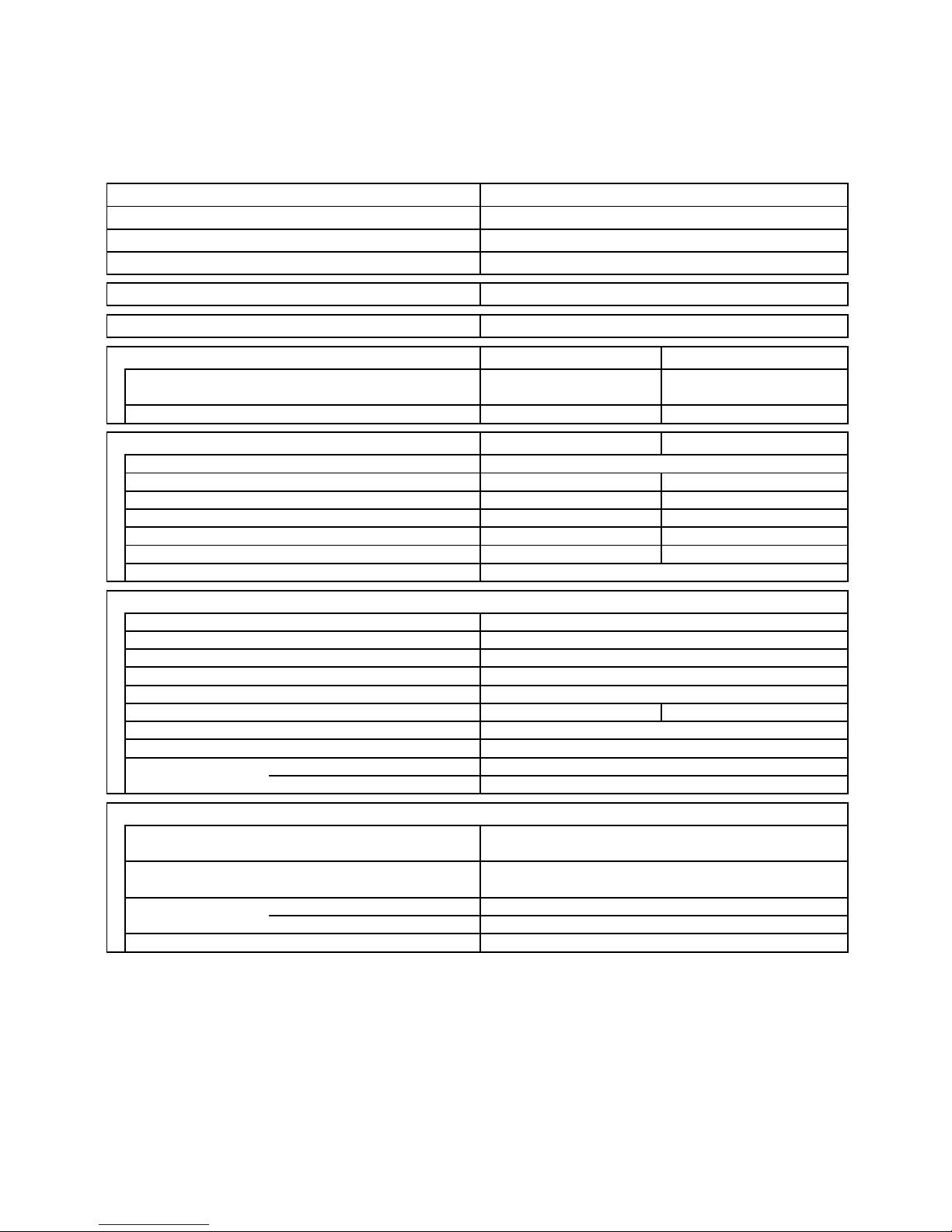
2. SPECIFICATIONS
2-1. Unit Specifications
Outdoor Unit SAP-CMRV1424EH
DATA SUBJECT TO CHANGE WITHOUT NOTICE.
Remarks:
1.The Values shown in perfromance section and electrical rating section above are based on the following unit combination.
For other combination unit, please refer to the "Unit Combination Table" in this manual.
Indoor Unit: SAP-KMRV94EH 2units Outdoor Unit: SAP-CMRV1424EH 1unit
2.Rating conditions are: Cooling: Indoor air temp. 27°C D.B. / 19°C W.B. Heating: Indoor air temp. 20°C D.B.
Outdoor air temp. 35°C D.B. / 24°C W.B. Outdoor air temp. 7°C D.B. / 6°C W.B.
-
20
Type
Voltage Rating
BTU/h
Capacity
Number of Operatable Indoor Units
Power Factor
Electrical Rating
645 x 921 x 386
42.0
98
98
14.5
DC Twin Rotary (Inverter)
-
4.86
m3/h
Number of Connectable Indoor Units
kW
Performance
Power Source
Max. Capacity of Operating Indoor Units
kW
Auto (Hi, Me, Lo)
Flare Type
A
Microprocessor
Features
4847Electric Expansion Valve
Refrigerant Control
Refrigerant / Amount charged at shipment
m
Refrigerant Tubing Connections
dB-A
Hi
Operation Sound
Max. allowable tubing length per unit
569 x 790 x 285
Refrigerant
Tube Diameter
mm
6.35 (1/4") x 2
9.52 (3/8") x 2
45.0
0.22
Narrow tube
Wide tube
mm (in.)
mm (in.)
Dimensions & Weight
m
3
2-Room Multi Outdoor Unit
230V
1,900
198 to 264
13,600
4.5
15,400
226.15
kg
Shipping
Unit Dimensions
Package Dimensions
Weight
Height x Width x Depth
Height x Width x Depth
mm
Shipping Volume
Cooling
Heating
1,900
Cooling
Heating
Net
( 2.0 to 5.0 )
Compressor
kg
g
E.E.R.
Fan Speeds
W/W
C.O.P.
Compressor Locked Rotor Amperes
W/W
R410A / 1,700
Controls
( 2.2 to 5.5 )
( 7,500 to 18,800 )
4.0
Air Circulation (High)
W
Power Input
V
A
Available Voltage Range
Running Amperes
220 to 240V Single-Phase 50Hz
4.32
( 6,800 to 17,100 )
4.1
925
4.1
925
%
8
Outdoor Unit SAP-CMRV1924EH
DATA SUBJECT TO CHANGE WITHOUT NOTICE.
Remarks:
1.The Values shown in perfromance section and electrical rating section above are based on the following unit combination.
For other combination unit, please refer to the "Unit Combination Table" in this manual.
Indoor Unit: SAP-KMRV94EH 1unit + SAP-KRV184EH 1unit Outdoor Unit: SAP-CMRV1924EH 1unit
2.Rating conditions are: Cooling: Indoor air temp. 27°C D.B. / 19°C W.B. Heating: Indoor air temp. 20°C D.B.
Outdoor air temp. 35°C D.B. / 24°C W.B. Outdoor air temp. 7°C D.B. / 6°C W.B.
3.*1 This data will be available in next issue of the Technical & Service Manual.
1,735
65.0
Type
Voltage Rating
BTU/h
Capacity
Number of Operatable Indoor Units
Number of Connectable Indoor Units
228.65
220 to 240V Single-Phase 50Hz
Electric Expansion Valve
-
4.21
-
Hi
Auto (Hi, Me, Lo)
Flare Type
A
Microprocessor
Features
52
50
Compressor Locked Rotor Amperes
14.5
0.36
Narrow tube
Wide tube
mm (in.)
mm (in.)
Dimensions & Weight
m
3
9.52 (3/8") x 2
860 x 1,032 x 413
740 x 900 x 320
Available Voltage Range
Running Amperes
V
Refrigerant Control
Operation Sound
m
Refrigerant Tubing Connections
dB-A
69.0
Max. allowable tubing length per unit
25
Refrigerant
Tube Diameter
mm
6.35 (1/4") x 2
kg
kg
2-Room Multi Outdoor Unit
230V
*1
198 to 264
19,100
7.3
24,900
Cooling
Heating
*1
Package Dimensions
Weight
Height x Width x Depth
Height x Width x Depth
mm
DC Twin Rotary (Inverter)
Shipping Volume
Net
Shipping
Compressor
Refrigerant / Amount charged at shipment
g
R410A / 2,800
Unit Dimensions
3.30
W/W
A
E.E.R.
W
Power Input
%
Power Factor
7.52
1,695
Fan Speeds
C.O.P.
W/W
Controls
( 8,200 to 28,700 )
5.6
( 7,200 to 23,200 )9898
Cooling
Heating
( 2.1 to 6.8 )
( 2.4 to 8.4 )
7.70
Max. Capacity of Operating Indoor Units
kW
Power Source
Electrical Rating
Air Circulation (High)
kW
Performance
m3/h

9
Outdoor Unit SAP-CMRV1934EH
DATA SUBJECT TO CHANGE WITHOUT NOTICE.
Remarks:
1.The Values shown in perfromance section and electrical rating section above are based on the following unit combination.
For other combination unit, please refer to the "Unit Combination Table" in this manual.
Indoor Unit: SAP-KMRV94EH 3units Outdoor Unit: SAP-CMRV1934EH 1unit
2.Rating conditions are: Cooling: Indoor air temp. 27°C D.B. / 19°C W.B. Heating: Indoor air temp. 20°C D.B.
Outdoor air temp. 35°C D.B. / 24°C W.B. Outdoor air temp. 7°C D.B. / 6°C W.B.
3.*1 This data will be available in next issue of the Technical & Service Manual.
1,735
( 9,900 to 23,200 )9898
Power Source
Electrical Rating
Air Circulation (High)
Performance
W
Power Input
( 3.4 to 8.4 )
( 11,600 to 28,700 )
5.6
( 2.9 to 6.8 )
Available Voltage Range
Running Amperes
V
7.70
Compressor
Refrigerant / Amount charged at shipment
g
E.E.R.
Fan Speeds
C.O.P.
W/W
Controls
R410A / 2,800
mm
DC Twin Rotary (Inverter)
Shipping Volume
Net
Unit Dimensions
Package Dimensions
Weight
Refrigerant
Tube Diameter
3.61
W/W
A
Shipping
Height x Width x Depth
Height x Width x Depth
69.0
Max. allowable tubing length per unit
25
3-Room Multi Outdoor Unit
230V
*1
198 to 264
19,100
7.3
24,900
Cooling
Heating
*1
mm
6.35 (1/4") x 3
kg
kg
740 x 900 x 320
65.0
Refrigerant Control
Operation Sound
m
Refrigerant Tubing Connections
dB-A
Hi
0.36
Narrow tube
Wide tube
mm (in.)
mm (in.)
Dimensions & Weight
m
3
9.52 (3/8") x 3
860 x 1,032 x 413
Auto (Hi, Me, Lo)
Flare Type
A
Microprocessor
Features
52
50
Compressor Locked Rotor Amperes
14.5
Electric Expansion Valve
-
4.21
-
m3/h
%
Power Factor
Cooling
6.88
1,550
Heating
3310.5
220 to 240V Single-Phase 50Hz
Type
Voltage Rating
BTU/h
Capacity
Number of Operatable Indoor Units
Number of Connectable Indoor Units
kW
Max. Capacity of Operating Indoor Units
kW

10
Outdoor Unit SAP-CMRV2444EH
DATA SUBJECT TO CHANGE WITHOUT NOTICE.
Remarks:
1.The Values shown in perfromance section and electrical rating section above are based on the following unit combination.
For other combination unit, please refer to the "Unit Combination Table" in this manual.
Indoor Unit: SAP-KMRV94EH 3units Outdoor Unit: SAP-CMRV2444EH 1unit
2.Rating conditions are: Cooling: Indoor air temp. 27°C D.B. / 19°C W.B. Heating: Indoor air temp. 20°C D.B.
Outdoor air temp. 35°C D.B. / 24°C W.B. Outdoor air temp. 7°C D.B. / 6°C W.B.
3.*1 This data will be available in next issue of the Technical & Service Manual.
2,000
8.87
2,0009898
Max. Capacity of Operating Indoor Units
kW
Power Source
Electrical Rating
Air Circulation (High)
W
Power Input
8.87
( 3.4 to 9.0 )
( 11,600 to 30,700 )
6.8
( 2.9 to 8.1 )
( 9,900 to 27,600 )
g
E.E.R.
Fan Speeds
C.O.P.
W/W
Controls
DC Twin Rotary (Inverter)
Shipping Volume
Net
Unit Dimensions
Package Dimensions
Weight
Refrigerant
Tube Diameter
Compressor
Refrigerant / Amount charged at shipment
Shipping
Height x Width x Depth
Height x Width x Depth
69.0
mm
4-Room Multi Outdoor Unit
230V
*1
198 to 264
23,200
8.6
29,300
Cooling
Heating
*1
kg
kg
740 x 900 x 320
65.0
V
Refrigerant Controlmm6.35 (1/4") x 4
3.40
W/W
A
Max. allowable tubing length per unit
25
R410A / 2,800
Operation Sound
m
Refrigerant Tubing Connections
dB-A
Hi
0.36
Narrow tube
Wide tube
mm (in.)
mm (in.)
Dimensions & Weight
m
3
9.52 (3/8") x 3 + 12.7 (1/2") x 1
860 x 1,032 x 413
Auto (Hi, Me, Lo)
Flare Type
A
Microprocessor
Features
52
50
Compressor Locked Rotor Amperes
14.5
Electric Expansion Valve
-
4.30
-
m3/h
%
Power Factor
Cooling
Heating
Available Voltage Range
Running Amperes
4312.2
220 to 240V Single-Phase 50Hz
Type
Voltage Rating
BTU/h
Capacity
Number of Operatable Indoor Units
Number of Connectable Indoor Units
kW
Performance

11
Outdoor Unit SAP-CMRV3144EH
DATA SUBJECT TO CHANGE WITHOUT NOTICE.
Remarks:
1.The Values shown in perfromance section and electrical rating section above are based on the following unit combination.
For other combination unit, please refer to the "Unit Combination Table" in this manual.
Indoor Unit: SAP-KMRV94EH 4units Outdoor Unit: SAP-CMRV3144EH 1unit
2.Rating conditions are: Cooling: Indoor air temp. 27°C D.B. / 19°C W.B. Heating: Indoor air temp. 20°C D.B.
Outdoor air temp. 35°C D.B. / 24°C W.B. Outdoor air temp. 7°C D.B. / 6°C W.B.
3.*1 This data will be available in next issue of the Technical & Service Manual.
2,040
7.58
1,7259999
Max. Capacity of Operating Indoor Units
kW
Power Source
Electrical Rating
Air Circulation (High)
W
Power Input
8.96
( 3.4 to 9.8 )
( 11,600 to 33,400 )
8.0
( 2.9 to 9.2 )
( 9,900 to 31,400 )
g
E.E.R.
Fan Speeds
C.O.P.
W/W
Controls
DC Twin Rotary (Inverter)
Shipping Volume
Net
Unit Dimensions
Package Dimensions
Weight
Refrigerant
Tube Diameter
Compressor
Refrigerant / Amount charged at shipment
Shipping
Height x Width x Depth
Height x Width x Depth
86.0
mm
4-Room Multi Outdoor Unit
230V
*1
198 to 264
27,300
9.4
32,100
Cooling
Heating
*1
kg
kg
890 x 900 x 320
82.0
V
Refrigerant Controlmm6.35 (1/4") x 4
4.64
W/W
A
Max. allowable tubing length per unit
30
R410A / 3,800
Operation Sound
m
Refrigerant Tubing Connections
dB-A
Hi
0.43
Narrow tube
Wide tube
mm (in.)
mm (in.)
Dimensions & Weight
m
3
9.52 (3/8") x 2 + 12.7 (1/2") x 2
1,010 x 1,032 x 413
Auto (Hi, Me, Lo)
Flare Type
A
Microprocessor
Features
52
50
Compressor Locked Rotor Amperes
17.0
Electric Expansion Valve
-
4.61
-
m3/h
%
Power Factor
Cooling
Heating
Available Voltage Range
Running Amperes
4414.7
220 to 240V Single-Phase 50Hz
Type
Voltage Rating
BTU/h
Capacity
Number of Operatable Indoor Units
Number of Connectable Indoor Units
kW
Performance
12
2-2. Major Component Specifications
2-2-1. Outdoor Unit
Outdoor Unit SAP-CMRV1424EH
DATA SUBJECT TO CHANGE WITHOUT NOTICE.
CC
Ohm
CT (Peak current cut-off control)
Compressor Discharge Temp. Control
Operation cut-off control in abnormal ambient Temp.
Overload Relay
Model
Operation Temp.
Micro F
VAC
Type
Over- Current Protection
Micro F
VAC
T - R : 0.482
RED - WHT : 77.5
WHT - BLU : 77.5
R - S : 0.482
S - T : 0.482
DC Motor
8
CS-7L115
Open : 115oC, Close : 95oC
Q'ty ... Dia.
Compressor
mm
Type
Crankcase Heater
Control PCB
Safety Device
Rough Measure RPM (Cool:Hi / Heat:Hi)
Run Capacitor
Type
Model ... Q'ty
No. of Poles
W
Ohm
Nominal Output
Coil Resistance
50
750 / 750
BLU - RED : 77.5
CB-CMRV1424EH
Part No.
Fan Motor
Type
Compressor Model / Nominal Output
Compressor Oil ... Amount
Coil Resistance (Ambient Temp. 20oC)
--Yes
Heat Exchanger Coil
Microprocessor
250V 25A
Control Circuit Fuse
Controls
1 ... D420
Fan
Propeller
(Ambient Temp. 20oC)
DAJ12-55J71-CR ... 1
Face Area
m
2
0.452
Coil
Rows
Fin Pitch
mm
-
Yes
-
Internal Controller
Aluminum Plate Fin / Copper Tube
2
1.3
External Finish
Acrylic baked-on enamel finish
DC Twin Rotary (Hermetic)
C-6RVN93H0M / 1,000W
FV50S ... 350
Yes
Safety Device
Yes
-
Run Capacitor
13
Outdoor Unit SAP-CMRV1924EH
DATA SUBJECT TO CHANGE WITHOUT NOTICE.
CC
Ohm
CT (Peak current cut-off control)
Compressor Discharge Temp. Control
Operation cut-off control in abnormal ambient Temp.
Overload Relay
Model
Operation Temp.
Micro F
VAC
Type
Over- Current Protection
Over- Heat Protection
Micro F
VAC
DC Motor
Q'ty ... Dia.
Compressor
mm
Type
Crankcase Heater
Safety Device
Rough Measure RPM (Cool:Hi / Heat:Hi)
Run Capacitor
Type
Model ... Q'ty
No. of Poles
W
Ohm
8
Nominal Output
Coil Resistance
90
750 / 750
-
Control PCB
CB-CMRV1924EH
Part No.
Fan Motor
Type
Compressor Model / Nominal Output
Compressor Oil ... Amount
Coil Resistance (Ambient Temp. 20oC)
-
230V 25W
Heat Exchanger Coil
Microprocessor
250V 25A
Control Circuit Fuse
Controls
1 ... D460
Fan
Propeller
(Ambient Temp. 20oC)
SIC-71FW-D490-1 ... 1
Face Area
m
2
0.595
Coil
Rows
Fin Pitch
mm
-
Yes
-
Internal Controller
Aluminum Plate Fin / Copper Tube
2
1.4
Yes
Safety Device
Yes
-
Run Capacitor
CS-7LN115
Open : 115oC, Close : 100oC
Yes
External Finish
Acrylic baked-on enamel finish
DC Twin Rotary (Hermetic)
5KD240XAB21 / 1,700W
FV50S ... 900
U - V : 0.720
V - W : 0.708
W - U : 0.726
Yes

14
Outdoor Unit SAP-CMRV1934EH
DATA SUBJECT TO CHANGE WITHOUT NOTICE.
CC
Ohm
CT (Peak current cut-off control)
Compressor Discharge Temp. Control
Operation cut-off control in abnormal ambient Temp.
Overload Relay
Model
Operation Temp.
Micro F
VAC
Type
Over- Current Protection
Over- Heat Protection
Micro F
VAC
Yes
External Finish
Acrylic baked-on enamel finish
DC Twin Rotary (Hermetic)
5KD240XAB21 / 1,700W
FV50S ... 900
U - V : 0.720
V - W : 0.708
W - U : 0.726
Yes
Yes
Safety Device
Yes
-
Run Capacitor
CS-7LN115
Open : 115oC, Close : 100oC
-
Yes
-
Internal Controller
Aluminum Plate Fin / Copper Tube
2
1.4
Face Area
m
2
0.595
Coil
Rows
Fin Pitch
mm
Heat Exchanger Coil
Microprocessor
250V 25A
Control Circuit Fuse
Controls
1 ... D460
Fan
Propeller
(Ambient Temp. 20oC)
SIC-71FW-D490-1 ... 1
Control PCB
CB-CMRV1934EH
Part No.
Fan Motor
Type
Compressor Model / Nominal Output
Compressor Oil ... Amount
Coil Resistance (Ambient Temp. 20oC)
-
230V 25W
8
Nominal Output
Coil Resistance
90
750 / 750
-
Safety Device
Rough Measure RPM (Cool:Hi / Heat:Hi)
Run Capacitor
Type
Model ... Q'ty
No. of Poles
W
Ohm
DC Motor
Q'ty ... Dia.
Compressor
mm
Type
Crankcase Heater

15
Outdoor Unit SAP-CMRV2444EH
DATA SUBJECT TO CHANGE WITHOUT NOTICE.
CC
Ohm
CT (Peak current cut-off control)
Compressor Discharge Temp. Control
Operation cut-off control in abnormal ambient Temp.
Overload Relay
Model
Operation Temp.
Micro F
VAC
Type
Over- Current Protection
Over- Heat Protection
Micro F
VAC
DC Motor
Q'ty ... Dia.
Compressor
mm
Type
Crankcase Heater
Safety Device
Rough Measure RPM (Cool:Hi / Heat:Hi)
Run Capacitor
Type
Model ... Q'ty
No. of Poles
W
Ohm
8
Nominal Output
Coil Resistance
90
750 / 750
-
Control PCB
CB-CMRV2444EH
Part No.
Fan Motor
Type
Compressor Model / Nominal Output
Compressor Oil ... Amount
Coil Resistance (Ambient Temp. 20oC)
-
230V 25W
Heat Exchanger Coil
Microprocessor
250V 25A
Control Circuit Fuse
Controls
1 ... D460
Fan
Propeller
(Ambient Temp. 20oC)
SIC-71FW-D490-1 ... 1
Face Area
m
2
0.595
Coil
Rows
Fin Pitch
mm
-
Yes
-
Internal Controller
Aluminum Plate Fin / Copper Tube
2
1.4
Yes
Safety Device
Yes
-
Run Capacitor
CS-7LN115
Open : 115oC, Close : 100oC
Yes
External Finish
Acrylic baked-on enamel finish
DC Twin Rotary (Hermetic)
5KD240XAB21 / 1,700W
FV50S ... 900
U - V : 0.720
V - W : 0.708
W - U : 0.726
Yes
16
Outdoor Unit SAP-CMRV3144EH
DATA SUBJECT TO CHANGE WITHOUT NOTICE.
CC
Ohm
CT (Peak current cut-off control)
Compressor Discharge Temp. Control
Operation cut-off control in abnormal ambient Temp.
Overload Relay
Model
Operation Temp.
Micro F
VAC
Type
Over- Current Protection
Over- Heat Protection
Micro F
VAC
Yes
External Finish
Acrylic baked-on enamel finish
DC Twin Rotary (Hermetic)
5JD420XAB22 / 3,000W
FV50S ... 1,200
U - V : 0.435
V - W : 0.441
W - U : 0.452
Yes
Yes
Safety Device
Yes
-
Run Capacitor
CS-7LN115
Open : 115oC, Close : 100oC
-
Yes
-
Internal Controller
Aluminum Plate Fin / Copper Tube
2
1.4
Face Area
m
2
0.723
Coil
Rows
Fin Pitch
mm
Heat Exchanger Coil
Microprocessor
250V 25A
Control Circuit Fuse
Controls
1 ... D460
Fan
Propeller
(Ambient Temp. 20oC)
SIC-71FW-D490-1 ... 1
Control PCB
CB-CMRV3144EH
Part No.
Fan Motor
Type
Compressor Model / Nominal Output
Compressor Oil ... Amount
Coil Resistance (Ambient Temp. 20oC)
-
230V 25W
8
Nominal Output
Coil Resistance
90
750 / 750
-
Safety Device
Rough Measure RPM (Cool:Hi / Heat:Hi)
Run Capacitor
Type
Model ... Q'ty
No. of Poles
W
Ohm
DC Motor
Q'ty ... Dia.
Compressor
mm
Type
Crankcase Heater
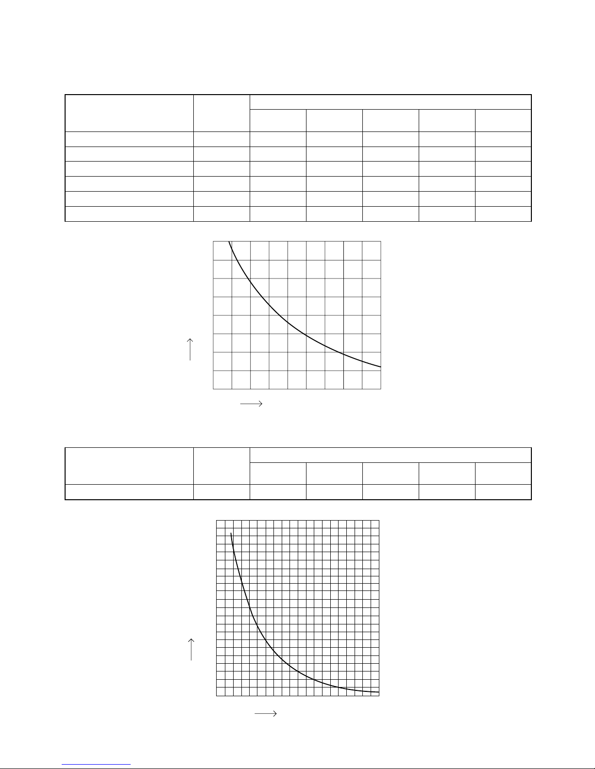
2-3. Other Component Specifications
0
0102030405060708090
40
60
80
100
120
140
160
180
200
20
Resistance (k ohm)
Temperature (°C)
40
35
30
25
20
15
10
5
0
-20-15-
10-50 5101520
Temperature (°C)
Resistance (k ohm)
Outdoor air temp sensor
Outdoor heat exchanger sensor
AW / AN sensor
BW / BN sensor
CW / CN sensor
DW / DN sensor
TKS295B
TKS292B
TKS292B
TKS292B
TKS292B
TKS292B
Model No.
of sensor
Sensor Name
1
1
1
1
0
0
1
1
1
1
0
0
1
1
1
1
1
0
Quantity of Sensor
1
1
1
1
1
1
1
1
1
1
1
1
SAPCMRV1424EH
SAPCMRV1924EH
SAPCMRV1934EH
SAPCMRV2444EH
SAPCMRV3144EH
Sensor Name
Compressor temp sensor TKS293B
Model No.
of sensor
111
Quantity of Sensor
11
SAPCMRV1424EH
SAPCMRV1924EH
SAPCMRV1934EH
SAPCMRV2444EH
SAPCMRV3144EH
17
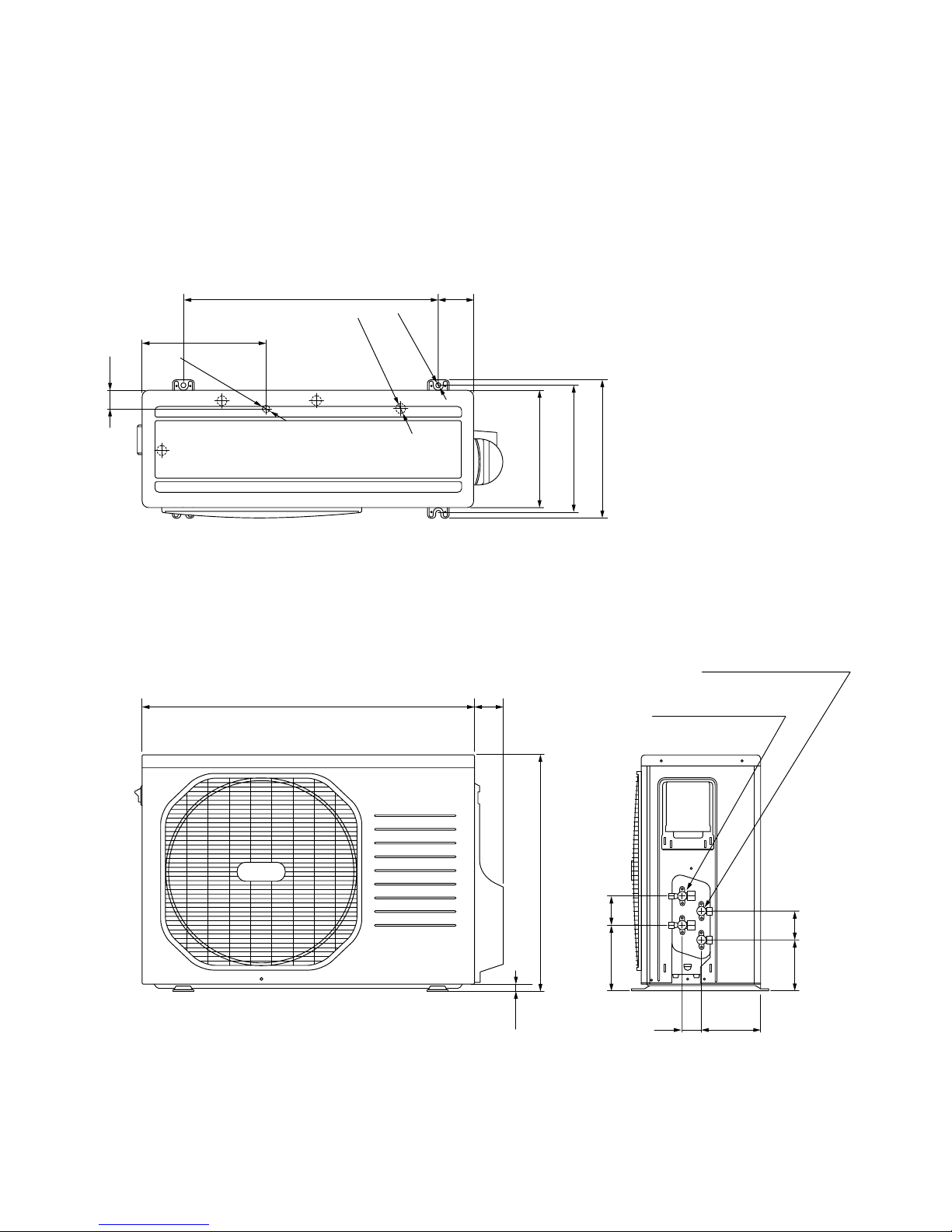
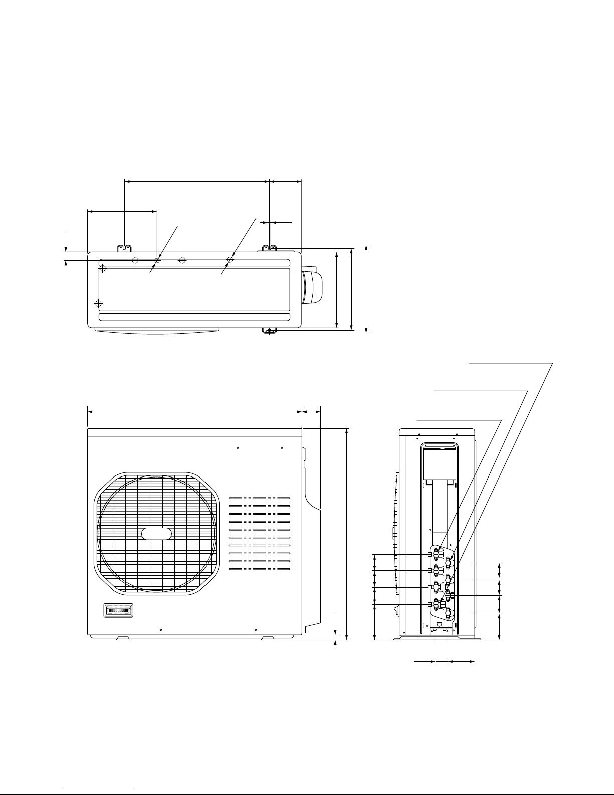
295
608 85
790 70
46
336
310
285
4-ID:23.6
ID:18
2-ID:12
569
15
70122
158 70
14246
Wide tube service valve
dia.9.52 (3/8"
)
× 2
Narrow tube service valve
dia.6.35 (1/4")
× 2
Unit: mm
3. DIMENSIONAL DATA
Outdoor Unit SAP-CMRV1424EH
18
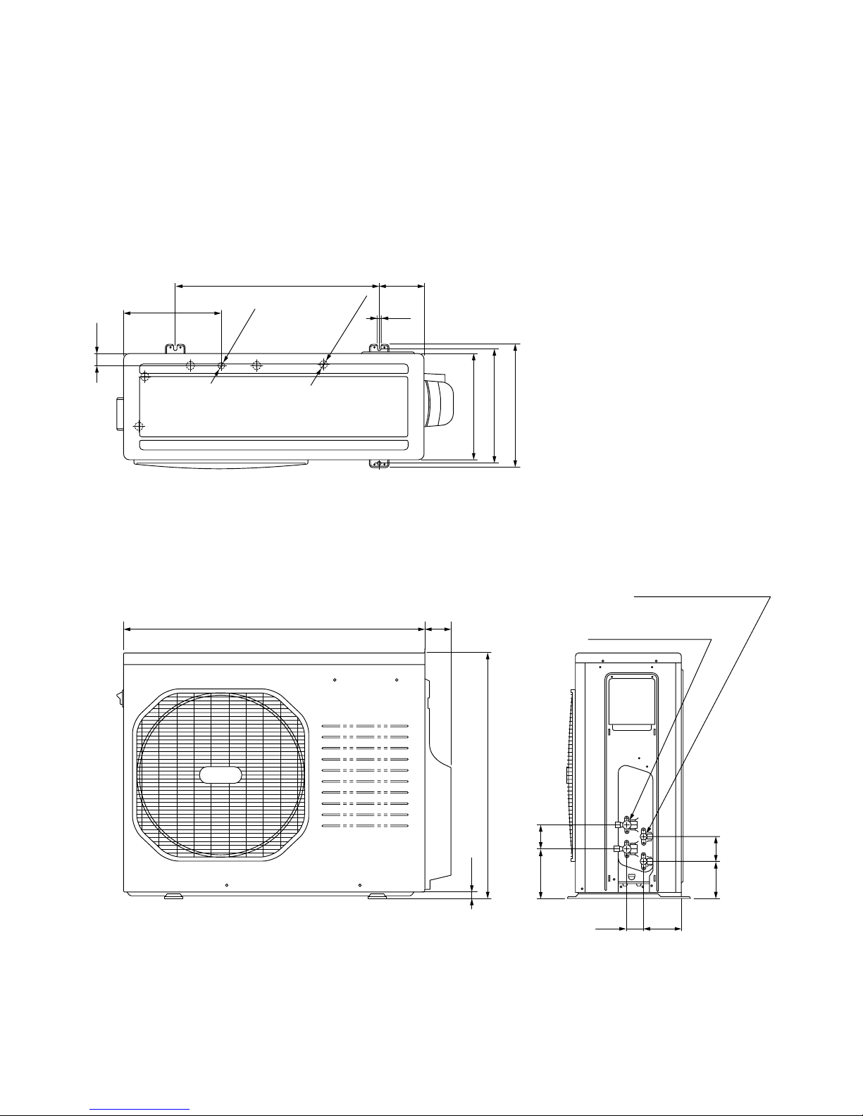
293
608 136
12
900 85
35
369
345
320
ID:18
5-ID:23.6
740
18
75113
150 72
11451
Wide tube service valve
dia.9.52 (3/8"
)
× 2
Narrow tube service valve
dia.6.35 (1/4")
× 2
Outdoor Unit SAP-CMRV1924EH
Unit: mm
19
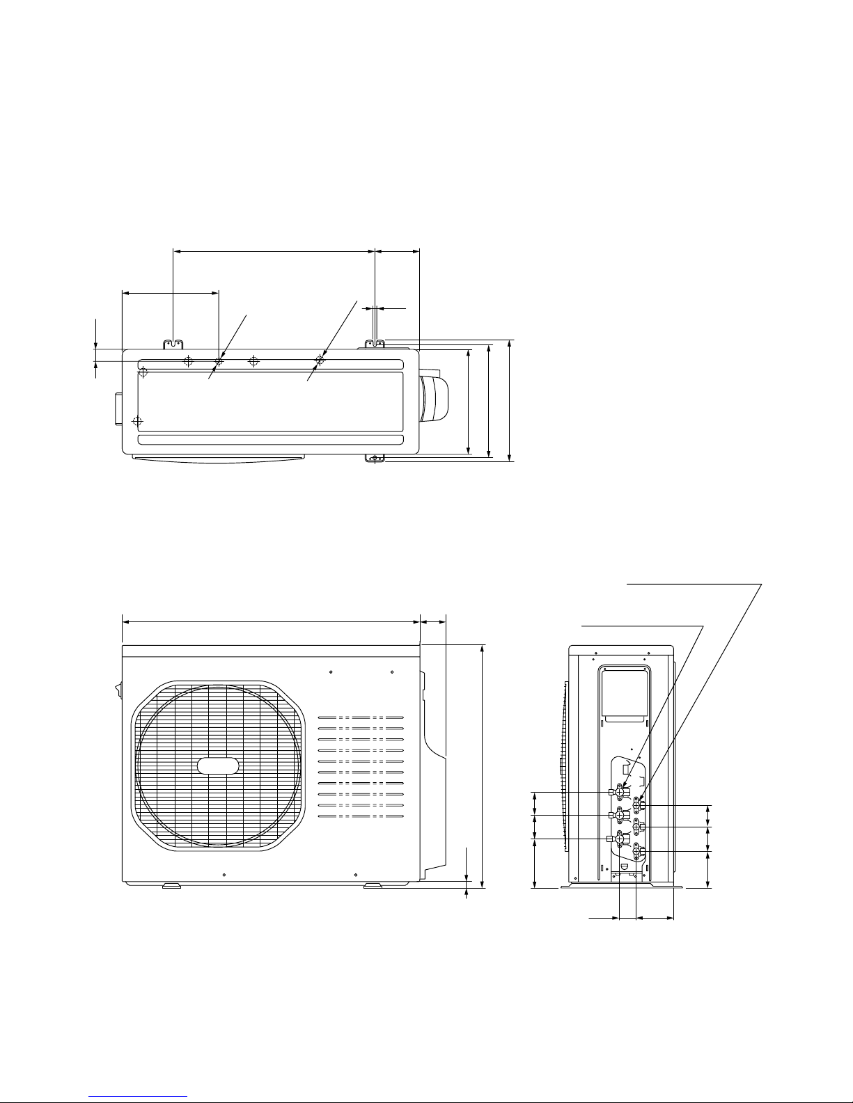
293
608 136
12
35
369
345
320
ID:18
5-ID:23.6
900 85
740
18
75 70113
150 72
70
11451
Wide tube service valve
dia.9.52 (3/8"
)
× 3
Narrow tube service valve
dia.6.35 (1/4")
× 3
Outdoor Unit SAP-CMRV1934EH
Unit: mm
20
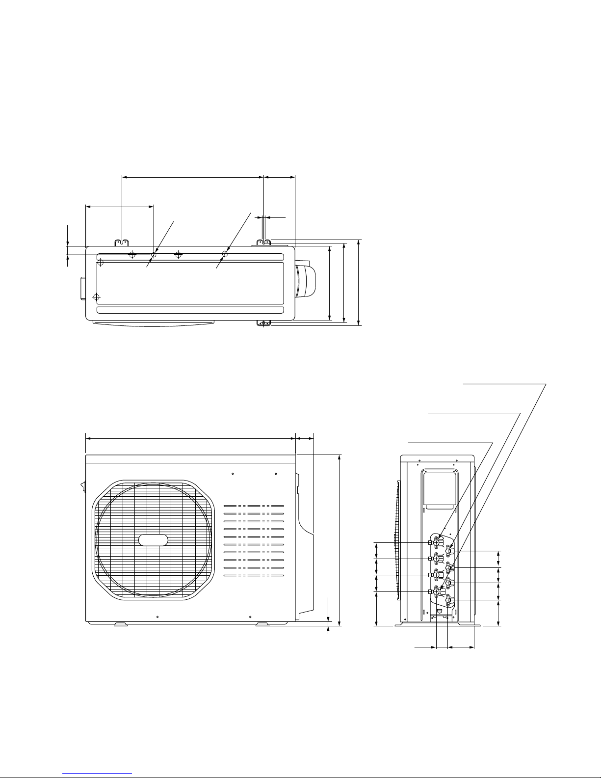
293
608 136
12
35
369
345
320
ID:18
5-ID:23.6
900 85
740
18
75 70113
150 72
70
11451
70
70
Wide tube service valve
dia.9.52 (3/8"
)
× 3
Narrow tube service valve
dia.6.35 (1/4")
× 4
Wide tube service valve
dia.12.70 (1/2")
× 1
Outdoor Unit SAP-CMRV2444EH
Unit: mm
21
293
608 136
12
35
369
345
320
ID:18
5-ID:23.6
900 85
890
18
75 70113
150 73
70
11451
70
70
Wide tube service valve
dia.9.52 (3/8"
)
× 2
Narrow tube service valve
dia.6.35 (1/4")
× 4
Wide tube service valve
dia.12.70 (1/2")
× 2
Outdoor Unit SAP-CMRV3144EH
Unit: mm
22

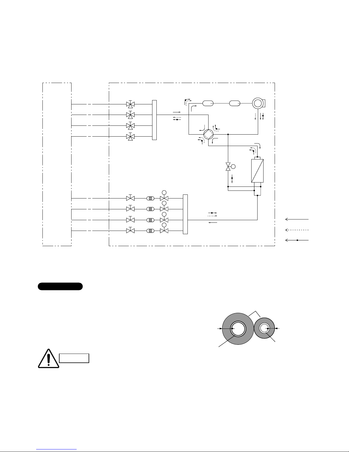
4. REFRIGERANT FLOW DIAGRAM
4-1. Refrigerant Flow Diagram
Outdoor Unit SAP-CMRV1424EH
Insulation of Refrigerant Tubing
Because capillary tubing is used in the outdoor unit, both the
wide and narrow tubes of this air conditioner become cold. To
prevent heat loss and wet floors due to dripping of
condensation, both tubes must be well insulated with a
proper insulation material. The thickness of the insulation
should be a min. 8 mm.
After a tube has been insulated,
never try to bend it into a narrow
curve because it can cause the tube
to break or crack.
Wide tube
Thickness:
Min. 8 mm
Insulation
Narrow tube
Thickness:
Min. 8 mm
IMPORTANT
CAUTION
Compressor
4-way
valve
Main
accumulator
Sub
accumulator
Service valve on
narrow tube
Service valve on
wide tube
Wide tube
BN
AN
BW
AW
O.D.9.52mm
O.D.9.52mm
Narrow tube
O.D.6.35mm
O.D.6.35mm
Heat exchanger
Capillary
tube for
split flow
Cooling cycle
Heating cycle
Defrosting cycle
Indoor unit Outdoor unit
Defrost valve
for hot gas bypass
Strainer
S
M
M
Electric
expansion
valve
Muffler
23

Narrow tube
O.D.6.35mm
O.D.6.35mm
Outdoor Unit SAP-CMRV1924EH
Insulation of Refrigerant Tubing
Because capillary tubing is used in the outdoor unit, both the
wide and narrow tubes of this air conditioner become cold. To
prevent heat loss and wet floors due to dripping of
condensation, both tubes must be well insulated with a
proper insulation material. The thickness of the insulation
should be a min. 8 mm.
After a tube has been insulated,
never try to bend it into a narrow
curve because it can cause the tube
to break or crack.
Wide tube
Thickness:
Min. 8 mm
Insulation
Narrow tube
Thickness:
Min. 8 mm
IMPORTANT
CAUTION
Compressor
4-way
valve
Main
accumulator
Sub
accumulator
Service valve on
narrow tube
Service valve on
wide tube
Wide tube
BN
AN
BW
AW
O.D.9.52mm
O.D.9.52mm
Heat exchanger
Cooling cycle
Heating cycle
Defrosting cycle
Indoor unit Outdoor unit
Defrost valve
for hot gas bypass
Strainer
S
M
M
Electric
expansion
valve
Header
Header
24

Outdoor Unit SAP-CMRV1934EH
Insulation of Refrigerant Tubing
Because capillary tubing is used in the outdoor unit, both the
wide and narrow tubes of this air conditioner become cold. To
prevent heat loss and wet floors due to dripping of
condensation, both tubes must be well insulated with a
proper insulation material. The thickness of the insulation
should be a min. 8 mm.
After a tube has been insulated,
never try to bend it into a narrow
curve because it can cause the tube
to break or crack.
Wide tube
Thickness:
Min. 8 mm
Insulation
Narrow tube
Thickness:
Min. 8 mm
IMPORTANT
CAUTION
Compressor
4-way
valve
Main
accumulator
Sub
accumulator
Service valve on
narrow tube
Service valve on
wide tube
Wide tube
CN
BN
AN
CW
BW
AW
O.D.9.52mm
O.D.9.52mm
O.D.9.52mm
Narrow tube
O.D.6.35mm
O.D.6.35mm
O.D.6.35mm
Heat exchanger
Cooling cycle
Heating cycle
Defrosting cycle
Indoor unit Outdoor unit
Defrost valve
for hot gas bypass
Strainer
S
M
M
Electric
expansion
valve
Header
Header
M
25

Outdoor Unit SAP-CMRV2444EH
Insulation of Refrigerant Tubing
Because capillary tubing is used in the outdoor unit, both the
wide and narrow tubes of this air conditioner become cold. To
prevent heat loss and wet floors due to dripping of
condensation, both tubes must be well insulated with a
proper insulation material. The thickness of the insulation
should be a min. 8 mm.
After a tube has been insulated,
never try to bend it into a narrow
curve because it can cause the tube
to break or crack.
Wide tube
Thickness:
Min. 8 mm
Insulation
Narrow tube
Thickness:
Min. 8 mm
IMPORTANT
CAUTION
Compressor
4-way
valve
Main
accumulator
Sub
accumulator
Service valve on
narrow tube
Service valve on
wide tube
Wide tube
DN
CN
BN
AN
DW
CW
BW
AW
O.D.9.52mm
O.D.9.52mm
O.D.9.52mm
O.D.12.7mm
Narrow tube
O.D.6.35mm
O.D.6.35mm
O.D.6.35mm
O.D.6.35mm
Heat exchanger
Cooling cycle
Heating cycle
Defrosting cycle
Indoor unit Outdoor unit
Defrost valve
for hot gas bypass
Strainer
S
M
M
Electric
expansion
valve
Header
Header
M
M
26
Outdoor Unit SAP-CMRV3144EH
Insulation of Refrigerant Tubing
Because capillary tubing is used in the outdoor unit, both the
wide and narrow tubes of this air conditioner become cold. To
prevent heat loss and wet floors due to dripping of
condensation, both tubes must be well insulated with a
proper insulation material. The thickness of the insulation
should be a min. 8 mm.
After a tube has been insulated,
never try to bend it into a narrow
curve because it can cause the tube
to break or crack.
Wide tube
Thickness:
Min. 8 mm
Insulation
Narrow tube
Thickness:
Min. 8 mm
IMPORTANT
CAUTION
Compressor
4-way
valve
Main
accumulator
Sub
accumulator
Service valve on
narrow tube
Service valve on
wide tube
Wide tube
DN
CN
BN
AN
DW
CW
BW
AW
O.D.9.52mm
O.D.9.52mm
O.D.12.7mm
O.D.12.7mm
Narrow tube
O.D.6.35mm
O.D.6.35mm
O.D.6.35mm
O.D.6.35mm
Heat exchanger
Cooling cycle
Heating cycle
Defrosting cycle
Indoor unit Outdoor unit
Defrost valve
for hot gas bypass
Strainer
S
M
M
Electric
expansion
valve
Header
Header
M
M
27

5. PERFORMANCE DATA
5-1. Temperature Charts
This data will be available in next issue of the Technical & Service Manual.
5-2. Heating Performance
This data will be available in next issue of the Technical & Service Manual.
28
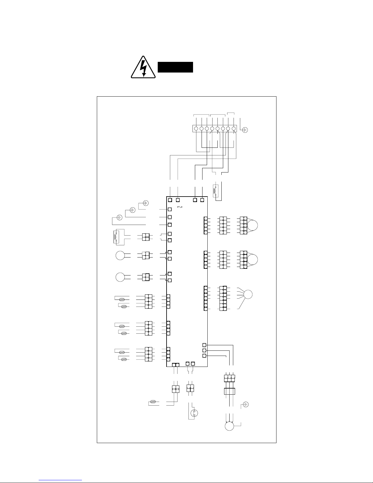
WARNING
To avoid electrical shock hazard, be sure to
disconnect power before checking, servicing
and/or cleaning any electrical parts.
6. ELECTRICAL DATA
6-1. Electric Wiring Diagrams
Outdoor Unit SAP-CMRV1424EH
8FA2-5257-56900-1
YEL
BLU
RED
BLK
WHT
REACTANCE
CONTROLLER
BLK
BLK
BLK
BLK
WHT
COIL/OUTDOOR
COIL
THERMISTOR
COMPRESSOR
THERMISTOR
WHT
RED
(2P) CONNECTOR
(2P) CONNECTOR
(4P) CONNECTOR
WHT
OUTDOOR
THERMISTOR
COMP
MAGNETIC COIL
(5P) CONNECTOR
RED
MV0
TERMINAL
PLATE
1234567
8
GND
A INDDOR
UNIT
B INDDOR
UNIT
TO INDDOR UNIT
POWER
SUPPLY
NL
WHT
1 2 3 4
1
2
11
22
YEL
YEL
BLK
BLK
YEL
YEL
BLK
BLK
1
1
2
2
3
3
4
4
A-TH
AW THERMISTOR
AN THERMISTOR
(4P) CONNECTOR
RED
1 2 3 4
YEL
YEL
YEL
YEL
YEL
YEL
YEL
YEL
1
1
2
2
3
3
4
4
B-TH
BW THERMISTOR
BN THERMISTOR
(4P) CONNECTOR
BLU
1 2 3 4
W W
YEL
YEL
YEL
YEL
YEL
YEL
YEL
YEL
1
1
2
2
3
3
4
4
5
5
GRY GRY
555
4
4
BLK BLK
444
3
3
YEL YEL
333
2
2
RED RED
222
1
1
ORG ORG
111
DEF1 DEF0
(2P) CONNECTOR
BLK
BLK
BLK
BLU
BLU
DEF
COIL
DEFROST VALVE
2
2
1
1
W W
RV1 RV0
(2P) CONNECTOR
WHT
BLK
BLK
BLU
BLU
RV
COIL
4WAY VALVE
2
2
1
1
W W
L2 L1 E-2
MV0
MAGNETIC COIL
(5P) CONNECTOR
BLU
MV1
FAN MOTOR
5
1 2 3 4 5 6 7
5
GRY GRY
555
4
4
BLK BLK
444
3
3
YEL YEL
333
2
2
RED RED
222
1
1
ORG ORG
111
MV1
(7P) CONNECTOR
WHT
7
YEL
7
6
BLU
6
5
RED
5
4
BLK
4
3
3
2
2
1
WHT
1
CN04 DCFM
(2P) CONNECTOR
WHT
WHT
WHT
WHT
WHT
2
2
1
1
GRN/YEL
W
E-1
GRN/YEL
W
E
GRN/YEL
W
W
REACTANCE
BLK
WHT
BLK
BLK
BLK
RED
BLU
WHT
ACIN1WACIN2
W
SI-AWSI-B
25A
FM
(3P)CONNECTOR
FERRITE
CORE
COMPRESSOR
MOTOR
WHT
S/U
C/W
R/V
CM
BLU
WHT
RED (PNK)
BLU
WHT
RED (PNK)
11223
3
GRN/YEL
W
W
V
W
U
OLR1
OLR0
W
W
W
(OLR)
OVERLOAD RELAY
112
2
WHT
WHT
WHT
29
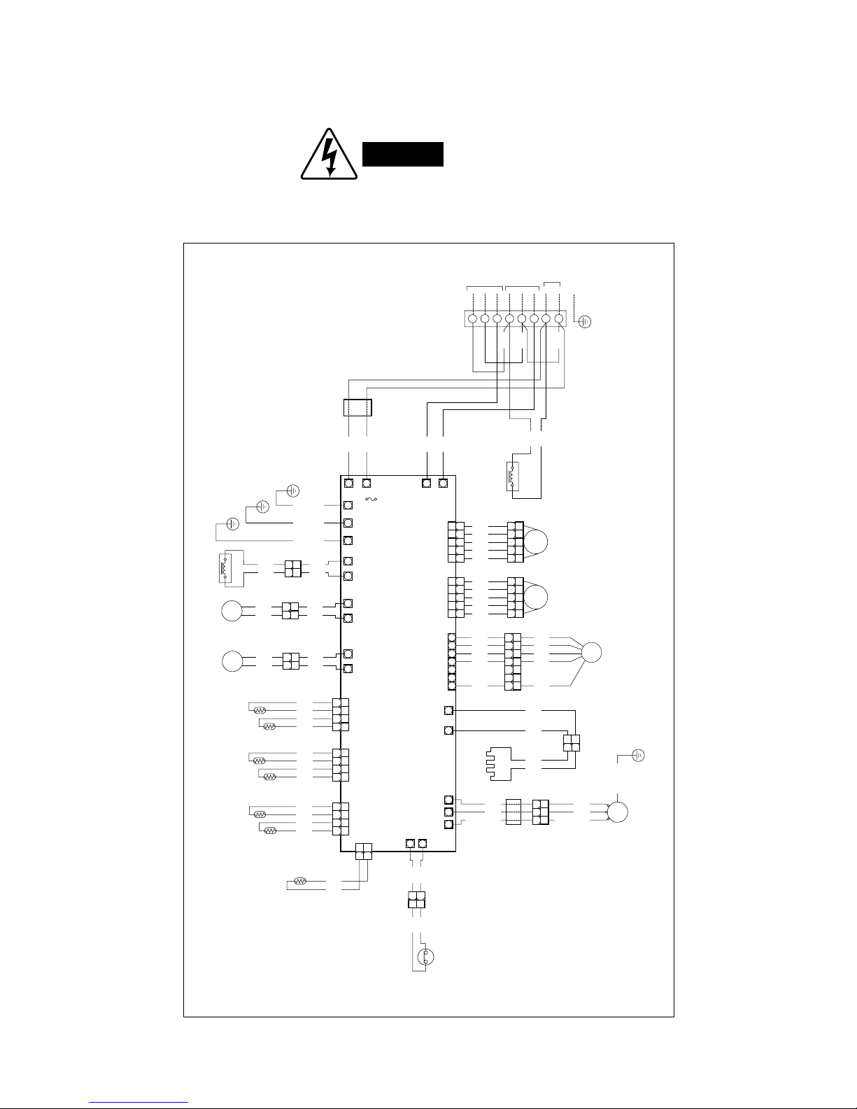
WARNING
To avoid electrical shock hazard, be sure to
disconnect power before checking, servicing
and/or cleaning any electrical parts.
Outdoor Unit SAP-CMRV1924EH
8FA2-5257-84200-0
HEATER
CRANKCASE
WHT
(2P) CONNECTOR
MAGNETIC COIL
MV0
5
GRY
5
5
4
BLK
4
4
3
YEL
3
3
2
RED
2
2
1
ORG
1
1
TERMINAL
PLATE
1234567
8
GND
A INDDOR
UNIT
B INDDOR
UNIT
TO INDDOR UNIT
POWER
SUPPLY
NL
WHT
REACTANCE
BLK
WHT
BLK
BLK
BLK
RED
BLU
WHT
ORG
WHT
BRN
BLU
RED
ORG
WHT
BRN
BLU
RED
FAN MOTOR
1 2 3 4 5 6 7
7654321
FM
FERRITE
CORE
(3P) CONNECTOR
COMPRESSOR
MOTOR
C/WS/U
R/V
WHT
CM
FERRITE
CORE
BLU
WHT
RED (PNK)
BLU
WHT
WHT
WHT
WHT
WHT
RED (PNK)
REACTANCE
CONTROLLER
BLK
BLK
WHT
COIL/OUTDOOR
COIL
THERMISTOR
COMPRESSOR
THERMISTOR
RED
(2P) CONNECTOR
OUTDOOR
THERMISTOR
COMP
1 2 3 4
1
2
1
2
YEL
YEL
BLK
BLK
1 2 3 4
A-TH
AW THERMISTOR
AN THERMISTOR
1 2 3 4
YEL
YEL
YEL
YEL
1 2 3 4
B-TH
BW THERMISTOR
BN THERMISTOR
1 2 3 4
W W
YEL
YEL
YEL
YEL
1 2 3 4
54321
DEF1 DEF0
(2P) CONNECTOR
BLK
BLK
BLK
BLU
BLU
DEF
COIL
DEFROST VALVE
2
2
1
1
W W
RV1 RV0
(2P) CONNECTOR
WHT
BLK
BLK
BLU
BLU
RV
COIL
4WAY VALVE
2
2
1
1
W W
L2 L1 E-2
MV0
MAGNETIC COIL
MV1
5
GRY
5
5
4
BLK
4
4
3
YEL
3
3
2
RED
2
2
1
ORG
1
1
54321
MV1
7654321
CN04 DCFM
(2P) CONNECTOR
WHT
WHT
WHT
WHT
WHT
2
2
1
1
GRN/YEL
W
E-1
GRN/YEL
W
E
GRN/YEL
W
W
ACIN1WACIN2
W
SI-AWSI-B
25A
OLR1
OLR0
W
W
(OLR)
OVERLOAD RELAY
112
2
WHT
WHT
WHT
GRN/YEL
1 2 3
321
W
W
HEATER1
W
HEATER0
W
V
W
U
W
221
1
30
 Loading...