

Page 1
Multimedia Projector
MODEL PLC-XP21N
Owner's
Manual
PLC-XP18N
Page 2
2
WARNING:
TO REDUCE THE RISK OF FIRE OR ELECTRIC SHOCK, DO NOT EXPOSE THIS APPLIANCE TO RAIN OR
MOISTURE.
This Projector has a grounding-type AC line plug. This is a safety feature to be sure that the plug will fit into the
power outlet. Do not try to defeat this safety feature.
This projector produces intense light from the projection lens. Do not stare directly into the lens as possible eye
damage could result. Be especially careful that children do not stare directly into the beam.
The Remote Control Unit, supplied to this projector, emits the laser beam as the Laser Pointer function from the
Laser Light Window while pressing the LASER button (for 1 minute). Do not look into the Laser Light Window or
shine the laser beam on yourself or other people. Eye damage may result.
This projector should be set in the way indicated. If not, it may result in fire hazard.
If the Projector will not be used for an extended time, unplug the new Projector from the power outlet.
READ AND KEEP THIS OWNER'S MANUAL FOR LATER USE.
As the owner of a new Multi-media Projector, you are probably eager to try out your new projector. Before you do, we
suggest that you spend a little time reading this manual to familiarize yourself with the operating procedures, so that you
will receive maximum satisfaction from the many features included in your new projector.
This owner's manual will acquaint you with your projector's features. Reading it will help us too. Through the years, we
have found that many service requests were not caused by problems with our projectors. They were caused by problems
that could have been prevented, if the owner had followed the instructions in the manual.
You can often correct operating problems yourself. If your projector fails to work properly, see "TROUBLESHOOTING"
section on pages 51 ~ 52 and try the solutions marked for each problem.
SAFETY PRECAUTIONS
TO THE OWNER
INFORMATION TO THE USER
NOTE : This equipment has been tested and found to comply with the limits for a Class A digital device,
pursuant to Part 15 of the FCC Rules. These limits are designed to provide reasonable protection
against harmful interference when the equipment is operated in a commercial environment. This
equipment generates, uses, and can radiate radio frequency energy and, if not installed and used
in accordance with the instruction manual, may cause harmful interference to radio
communications. Operation of this equipment in a residential area is likely to cause harmful
interference in which case the user will be required to correct the interference at his own expense.
CAUTION : TO REDUCE THE RISK OF ELECTRIC SHOCK, DO NOT REMOVE COVER (OR BACK).
NO USER-SERVICEABLE PARTS INSIDE EXCEPT LAMP REPLACEMENT. REFER
SERVICING TO QUALIFIED SERVICE PERSONNEL.
THIS SYMBOL INDICATES THAT
DANGEROUS VOLTAGE CONSTITUTING
A RISK OF ELECTRIC SHOCK IS
PRESENT WITHIN THIS UNIT.
THIS SYMBOL INDICATES THAT THERE
ARE IMPORTANT OPERATING AND
MAINTENANCE INSTRUCTIONS IN THE
OWNER'S MANUAL WITH THIS UNIT.
CAUTION
RISK OF ELECTRIC SHOCK
DO NOT OPEN
Page 3
PROJECTOR
(FRONT)
PROJECTOR
(SIDE)
WALL
50cm
20cm
50cm50cm
Unplug this projector from wall outlet and refer servicing to
qualified service personnel under the following conditions:
a. When the power cord or plug is damaged or frayed.
b. If liquid has been spilled into the projector.
c. If the projector has been exposed to rain or water.
d. If the projector does not operate normally by following the
operating instructions. Adjust only those controls that are
covered by the operating instructions as improper
adjustment of other controls may result in damage and
will often require extensive work by a qualified technician
to restore the projector to normal operation.
e. If the projector has been dropped or the cabinet has been
damaged.
f. When the projector exhibits a distinct change in
performance-this indicates a need for service.
When replacement parts are required, be sure the service
technician has used replacement parts specified by the
manufacturer that have the same characteristics as the
original part. Unauthorized substitutions may result in fire,
electric shock, or injury to persons.
Upon completion of any service or repairs to this projector,
ask the service technician to perform routine safety checks
to determine that the projector is in safe operating condition.
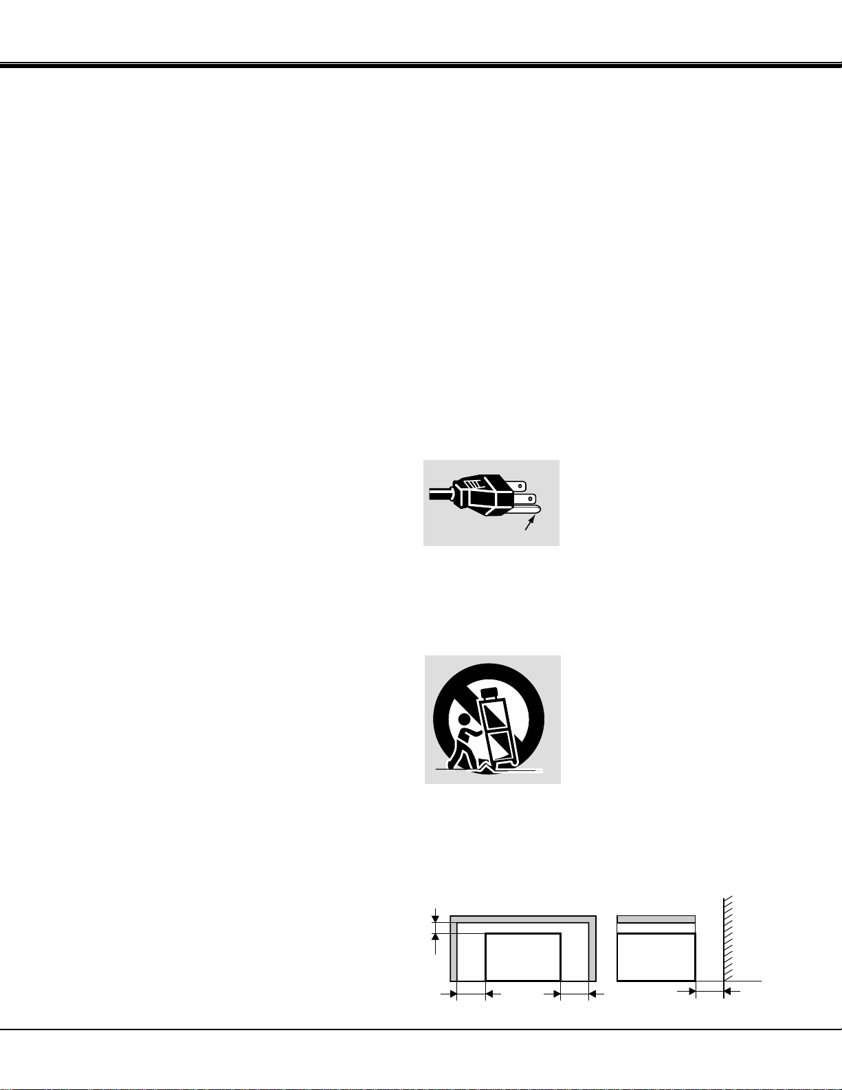
This projector is equipped with a
grounding type AC line plug.
Should you be unable to insert the
plug into the outlet, contact your
electrician. Do not defeat the safety
purpose of this grounding type plug.
Follow all warnings and instructions marked on the
projectors.
For added protection to the projector during a lightning
storm, or when it is left unattended and unused for long
periods of time, unplug it from the wall outlet. This will
prevent damage due to lightning and powerline surges.
An appliance and cart combination
should be moved with care. Quick
stops, excessive force, and uneven
surfaces may cause the appliance
and cart combination to overturn.
If the projector is to be built into a compartment or similarly
enclosed, the minimum distances must be maintained.
Do not cover the ventilation slot on the projector.
Heat build-up can reduce the service life of your projector,
and can also be dangerous.
3
IMPORTANT SAFETY INSTRUCTIONS
All the safety and operating instructions should be read
before the product is operated.
Read all of the instructions given here and retain them for
later use. Unplug this projector from AC power supply
before cleaning. Do not use liquid or aerosol cleaners. Use
a damp cloth for cleaning.
Do not use attachments not recommended by the
manufacturer as they may cause hazards.
Do not place this projector on an unstable cart, stand, or
table. The projector may fall, causing serious injury to a
child or adult, and serious damage to the projector. Use
only with a cart or stand recommended by the
manufacturer, or sold with the projector. Wall or shelf
mounting should follow the manufacturer's instructions,
and should use a mounting kit approved by the
manufacturer.
Do not expose this unit to rain or use near water... for
example, in a wet basement, near a swimming pool, etc...
Slots and openings in the back and bottom of the cabinet
are provided for ventilation, to insure reliable operation of
the equipment and to protect it from overheating.
The openings should never be covered with cloth or other
material, and the bottom opening should not be blocked by
placing the projector on a bed, sofa, rug, or other similar
surface. This projector should never be placed near or
over a radiator or heat register.
This projector should not be placed in a built-in installation
such as a bookcase unless proper ventilation is provided.
This projector should be operated only from the type of
power source indicated on the marking label. If you are not
sure of the type of power supplied, consult your authorized
dealer or local power company.
Do not overload wall outlets and extension cords as this
can result in fire or electric shock. Do not allow anything to
rest on the power cord. Do not locate this projector where
the cord may be damaged by persons walking on it.
Never push objects of any kind into this projector through
cabinet slots as they may touch dangerous voltage points
or short out parts that could result in a fire or electric
shock. Never spill liquid of any kind on the projector.
Do not attempt to service this projector yourself as opening
or removing covers may expose you to dangerous voltage
or other hazards. Refer all servicing to qualified service
personnel.
GROUND
Page 4

4
TABLE OF CONTENTS
PAGE
PAGE
MENU OPERATION 30-31
MODE SELECT 30
SOUND ADJUSTMENT 31
LANGUAGE ADJUSTMENT 31
VIDEO MODE 32-35
COLOR SYSTEM SELECT 32
VIDEO SOURCE SELECT 33
PICTURE IMAGE ADJUSTMENT 34
PICTURE SCREEN ADJUSTMENT 35
COMPUTER MODE 36-48
COMPUTER SYSTEM SELECT 36
COMPATIBLE COMPUTER SPECIFICATIONS 37
AUTO IMAGE FUNCTION 38
PICTURE IMAGE ADJUSTMENT 39
PICTURE POSITION ADJUSTMENT 40
PC ADJUSTMENT 41-44
PICTURE SCREEN ADJUSTMENT 45
OTHER FUNCTION SETTING 46-48
BLUE BACK 46-47
DISPLAY 46-47
CEILING 46-47
REAR 46-47
SPLIT WIPE 46-47
POWER MANAGEMENT 46-47
REMOTE CONTROL (Mode 1 or Mode 2) 46-47
LAMP AGE 48
APPENDIX 49-53
MAINTENANCE 49-51
TEMPERATURE WARNING INDICATOR 49
AIR FILTER CARE AND CLEANING 49
LAMP REPLACEMENT 50
CLEANING THE LENS 51
TROUBLESHOOTING 51-52
TECHNICAL SPECIFICATIONS 53
FEATURES AND DESIGN 5
COMPATIBILITY 5
IMAGE RESOLUTION 5
AUTOMATIC MULTISCANNING SYSTEM 5
MULTILANGUAGE MENU DISPLAY 5
LASER POINTER FUNCTION 5
OTHER FEATURES 5
UNPACKING THE PROJECTOR 5
TRADEMARKS 5
INSTALLATION 6-9
NAME OF EACH PART OF THE PROJECTOR 6
SETTING-UP THE PROJECTOR 7
MOVING THE PROJECTOR 8
POWER REQUIREMENTS 9
CONNECTING THE PROJECTOR 10-18
TERMINAL OF THE PROJECTOR 10
CONNECTING THE COMPUTER 11-15
CONNECTING THE VIDEO EQUIPMENT 16-18
BEFORE OPERATION 19-26
CONTROLS AND INDICATORS 19-20
OPERATION OF THE REMOTE CONTROL 21-23
CONTROL THE PROJECTOR 24-26
DIRECT OPERATION 24
MENU OPERATION 25-26
BASIC OPERATION 27-31
TURNING ON/OFF THE PROJECTOR 27
DIRECT OPERATION 27-29
MODE SELECT 27
SOUND VOLUME ADJUSTMENT 28
SOUND MUTE FUNCTION 28
ZOOM ADJUSTMENT 28
FOCUS ADJUSTMENT 28
DIGITAL ZOOM FUNCTION 28
KEYSTONE FUNCTION 28
NO SHOW FUNCTION 29
FREEZE PICTURE FUNCTION 29
AUTO IMAGE FUNCTION 29
NORMAL PICTURE FUNCTION 29
P-TIMER FUNCTION 29
Page 5

5
FEATURES AND DESIGN
The projector is a multimedia projector that combines powerful and sophisticated features with easy-to-use, intuitive
controls. Built-in multimedia features include audio, a palette of 16.77 million colors and active matrix liquid crystal
display (LCD) technology. The projector is ideal for high-performance business, training and imaging applications that
demand exceptional color quality.
COMPATIBILITY
IMAGE RESOLUTION
UNPACKING THE PROJECTOR
TRADEMARKS
AUTOMATIC MULTISCANNING SYSTEM
MULTILANGUAGE MENU DISPLAY
The projector is compatible with many different types of
personal computers and video devices, including:
● IBM-compatible computers, including laptops, up to
1280 x 1024 resolution.
● Apple Macintosh and PowerBook computers up to
1280 x 1024 resolution.
● Various VCRs, video disc players, video cameras,
DVD players, satellite TV tuners or other AV
equipment using any of the worldwide video
standards, including NTSC, NTSC4.43, PAL, PAL-M,
PAL-N and SECAM.
The resolution of the projector's projected image is 1024
x 768. The projector displays computer images just as
they appear on your computer's monitor. Screen
resolutions between 1024 x 768 and 1280 x 1024 are
compressed to 1024 x 768. The projector cannot display
screen resolutions above 1280 x 1024. If your computer's
screen resolution is higher than 1280 x 1024, reset it to a
lower resolution before you connect the projector.
This projector can detect display signals from most
personal computers currently distributed. It is free from
complicated adjustments to project picture images from
PC.
The projector comes with the parts listed below. Check to
find all the parts are included. If any parts are missing,
contact an authorized dealer or service station.
● Owner's Manual.
● AC Power Cord.
● Remote Control Unit.
● Batteries for Remote Control Units.
● VGA Cable.
● Mouse Cable for PS/2 port.
● Mouse Cable for serial port.
● Mouse Cable for ADB port.
● VGA/MAC Adapter.
● Protective Dust Cover.
● Lens Cover.
● Apple, Macintosh, and PowerBook are trademarks or
registered trademarks of Apple Computer, Inc.
● IBM and PS/2 are trademarks or registered trademarks
of International Business Machines, Inc.
● Windows is a trademarks or registered trademarks of
Microsoft Corporation.
● Other trademarks are the property of their respective
owners
LASER POINTER FUNCTION
The Remote Control Unit of this projector includes the
Laser Pointer function providing the ability to point and
highlight during presentations.
OTHER FEATURES
This projector has Motor Zoom/Focus, No Show, Picture
Freeze, Keystone, Mute Functions.
MENU DISPLAY is displayed with ; English, German,
French, Italian, Spanish and Japanese.
Page 6
INFRARED
REMOTE
RECEIVER
6
EXHAUST VENT
CAUTION HOT AIR!
Air blown from the exhaust vent is hot.
Observe the following when handling your
projector or choosing a location to install it.
● Keep heat-sensitive objects away from the
exhaust port.
● If you set the projector on top of a metallic
surface, the surface will become hot because of
the hot air exhaust. Be careful when handling.
● Do not touch the cabinet near to the exhaust
vent area, and especially screws and metallic
parts. These parts will become hot while the
projector is used.
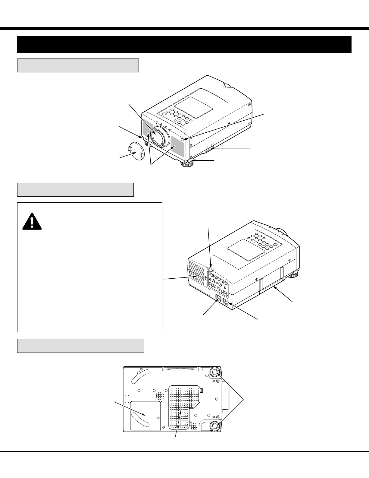
FRONT OF THE PROJECTOR
REAR OF THE PROJECTOR
SPEAKERS
INFRARED
REMOTE
RECEIVER
PROJECTION LENS
REMOVABLE
LENS COVER
MAIN ON/OFF
SWITCH
CARRYING
HANDLE
POWER CORD
CONNECTOR
ADJUSTABLE
FEET
AIR INTAKE VENT
BOTTOM OF THE PROJECTOR
LAMP
COVER
NAME OF EACH PART OF THE PROJECTOR
INSTALLATION
AIR INTAKE VENT
FEET LOCK
LATCH
FEET LOCK
LATCH
Page 7
100"
60"
40"
150"
200"
250"
77"
46"
31"
115"
154"
192"
H1
H2
231"
300"
400"
308"
7
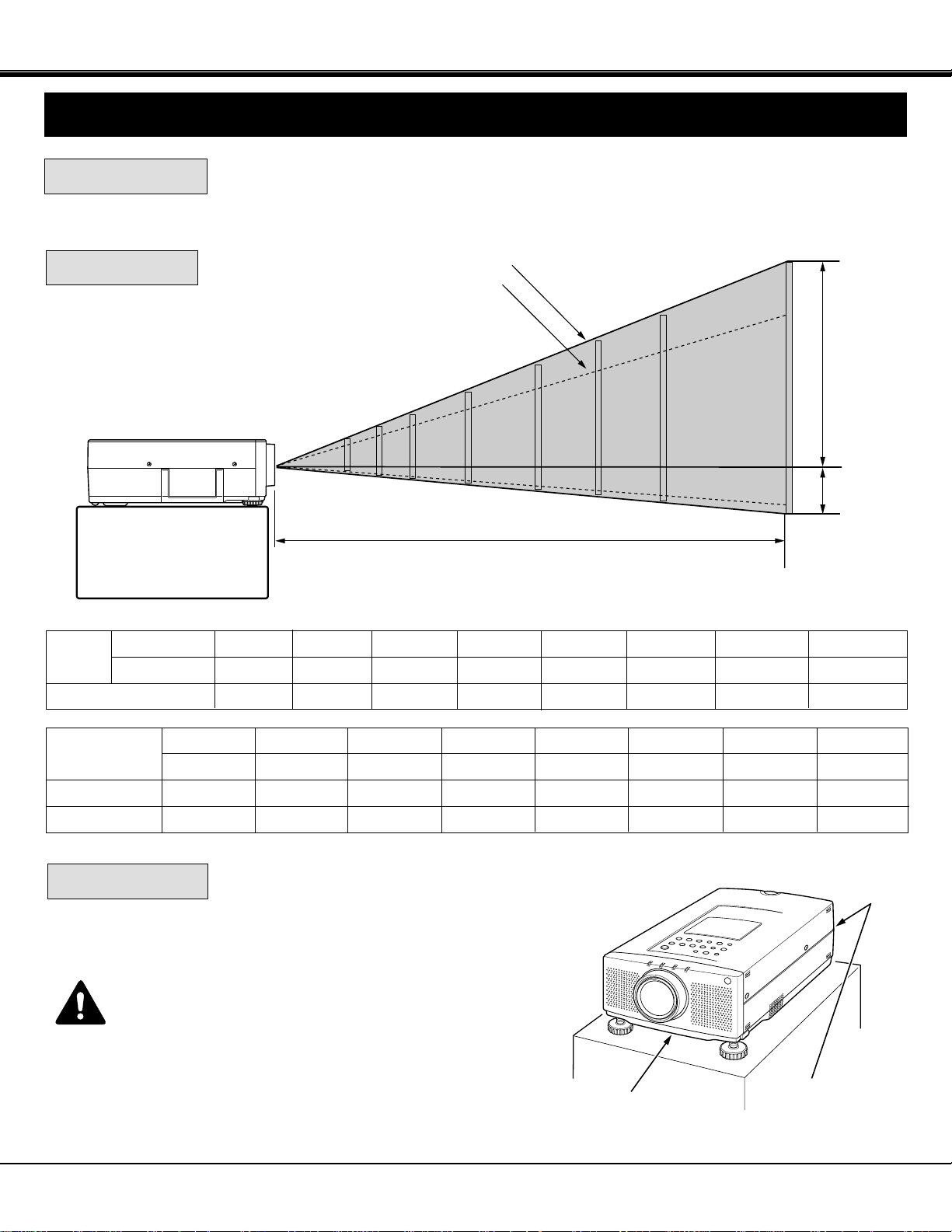
POSITIONING:
ROOM LIGHT
● This projector is basically designed to project on a flat projection surface.
● This projector can be focused from 4.6' (1.4 m) ~ 47.3' (14.4 m).
● Refer to the figure below as an example when positioning the projector to the screen.
Minimum Zoom
Maximum Zoom
DISTANCE
SETTING-UP THE PROJECTOR
INSTALLATION
This projector is equipped with cooling fan to protect it from
overheating. Pay attention to the following to ensure proper
ventilation and avoid a possible risk of fire and malfunction.
● Do not cover the vents with papers or other materials.
●
Keep the rear grill at least 3 feet (1 m) away from any
object.
● Make sure that there are no objects under the projector.
An object under the projector may prevent the projector
from taking the cooling air through the bottom vent.
VENTILATION
AIR INTAKE VENT
(BOTTOM SIDE)
EXHAUST VENT
(REAR SIDE)
400"
308"
47.3' (14.4m)
Screen
Size
Max. Zoom
Min. Zoom
Distance
40"
31"
4.6' (1.4m)
60"
46"
7.2' (2.2m)
100"
77"
11.8' (3.6m)
150"
115"
17.7' (5.4m)
200"
154"
23.6' (7.2m)
250"
192"
29.5' (9.0m)
300"
231"
35.4' (10.8m)
Screen Size
(W x H) inch
Height (H1)
Height (H2)
40"
32 x 24
22.8 inch
1.2 inch
60"
48 x 36
34.2 inch
1.8 inch
100"
80 x 60
57.1 inch
2.9 inch
150"
120 x 90
85.7 inch
4.3 inch
200"
160 x 120
114.3 inch
5.7 inch
250"
200 x 150
142.8 inch
7.2 inch
300"
240 x 180
171.4 inch
8.6 inch
400"
320 x 240
228.6 inch
11.4 inch
The level of brightness in a room has a great
influence on picture quality. It is recommended
to limit ambient lighting in order to provide the
best image.
Page 8
DOWN
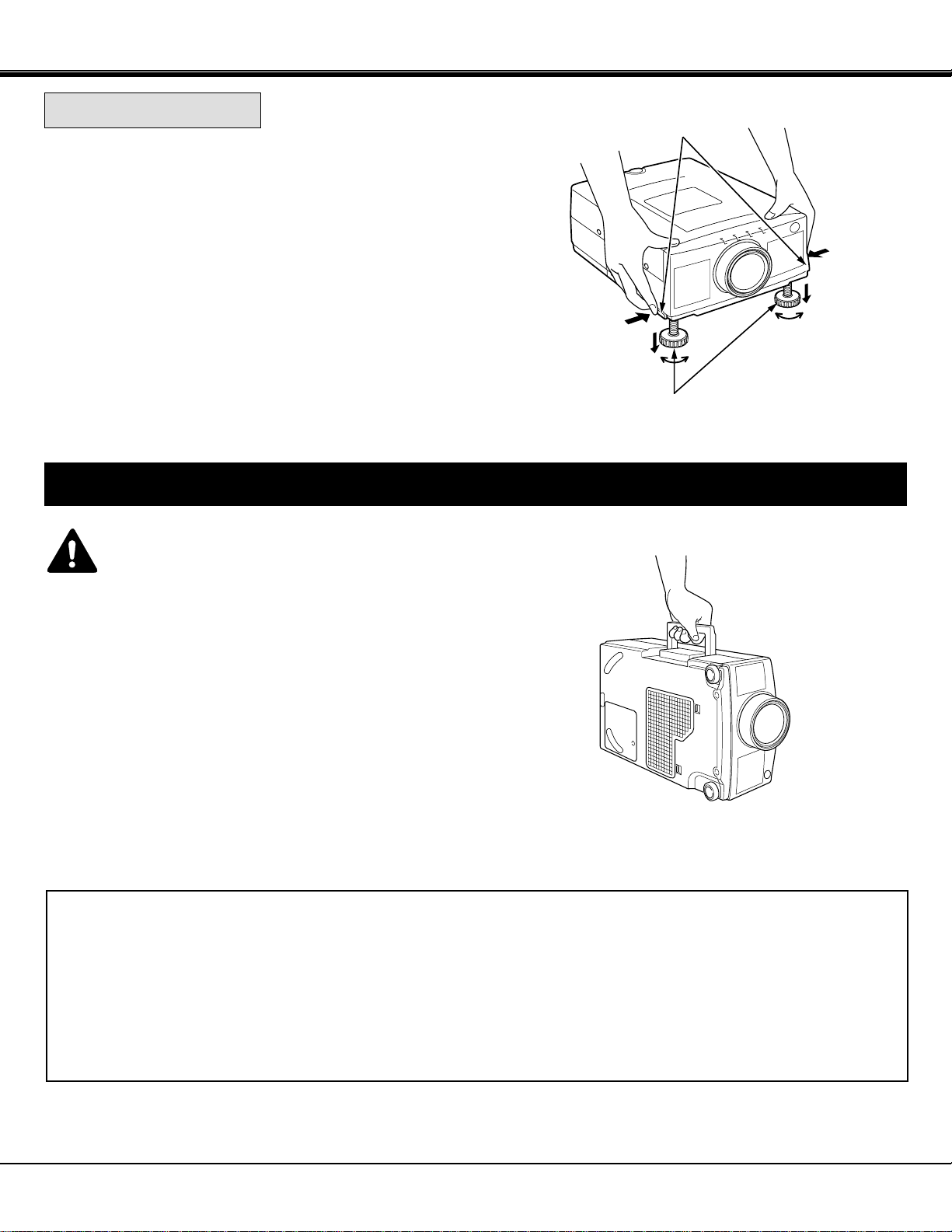
CAUTION IN CARRYING OR TRANSPORTING THE PROJECTOR
● Do not drop or bump the projector, otherwise damages or malfunctions may result.
● When transporting the projector, use a Sanyo recommended Carrying Case.
● Do not transport the projector by using a courier or transport service in an unsuitable transport case. This may cause
damage to the projector. To transport the projector through a courier or transport service, use a Sanyo recommended
Case.
● For a carrying or transportation cases, contact a Sanyo authorized dealer.
8
Use the carrying handle when moving the projector.
Replace the lens cover and retract the adjustable feet when
moving the projector to prevent damage to the projector.
ADJUSTABLE
FEET
FEET LOCK LATCHES
MOVING THE PROJECTOR
INSTALLATION
UP
UP
DOWN
Picture tilt and projection angle can be adjusted by rotating the
ADJUSTABLE FEET. Projection angle can be adjusted 0 to 6°.
ADJUSTABLE FEET
Lift the front of the projector and press the FEET LOCK
LATCHES on both sides of the projector.
Release the FEET LOCK LATCHES to lock the ADJUSTABLE
FEET and rotate the ADJUSTABLE FEET to fine tune the
position and the tilt.
To shorten the ADJUSTABLE FEET, lift the front of the
projector and press and undo the FEET LOCK LATCHES.
1.
3.
2.
NOTE: The position and the keystone distortion of the image can
also be adjusted using the KEYSTONE function.
(See pages 28, 35 and 45).
Page 9
9
INSTALLATION
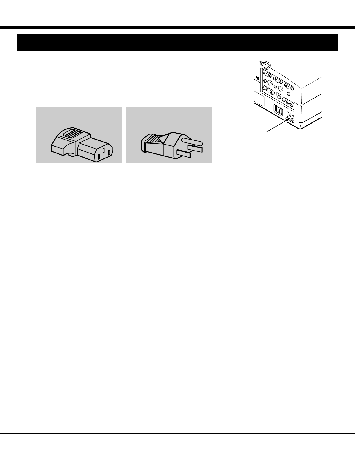
POWER REQUIREMENTS
Your projector uses nominal input voltages of 100-120 VAC. The projector
automatically selects the correct input voltage. The projector is designed to work
with single-phase power systems having a grounded neutral conductor. To reduce
the risk of electrical shock, do not plug into any other type of power system.
Consult your authorized dealer or service station if you are not sure what type of
power is supplied to your building.
Connect the AC power supply cord
(supplied) to the projector.
The socket-outlet must be near this
equipment and must be easily
accessible.
Projector side (Female)
AC outlet side (Male)
Page 10

10
REAR OF THE PROJECTOR
AUDIO INPUT JACKS
Used to connect an audio input to the projector.
VIDEO INPUT JACK
Used to connect a video source to the projector.
S-VIDEO INPUT JACK
Used to connect a S-VHS video source to the
projector.
COMPONENT VIDEO INPUT JACKS
Used to connect a component video source to the
projector.
EXT. SP. JACK (3.5 mm mini stereo type)
Used to connect an external speaker system.
Y Cb/Pb Cr/Pr
COMPUTER IN 1
COMPUTER IN 2
MONITOR OUT
EXT. SP
CONTROL PORT 2
CONTROL PORT 1
AUDIO 2
(STEREO)
(STEREO)
AUDIO 1
(STEREO)
(8Ω)
AUDIO
VIDEO
S-VIDEO
(MONO)
R L
AV IN
COMPUTER
1
2
3
6
7
10
9
4
5
8
11
12
1
2
3
4
5
6
8
9
10
11
12
7
CONNECTING THE PROJECTOR
TERMINAL OF THE PROJECTOR
COMPUTER INPUT-1 TERMINAL
Used to connect a computer to the projector.
COMPUTER INPUT-2 TERMINAL
Used to connect a computer to the projector.
MONITOR OUTPUT TERMINAL
Used to connect a monitor to the projector.
COMPUTER AUDIO INPUT-1 JACK
mini stereo type
Used to connect a computer audio input to the projector.
CONTROL PORT-1 CONNECTOR
Used to connect a mouse cable to the projector.
COMPUTER AUDIO INPUT-2 JACK
mini stereo type
Used to connect a computer audio input to the projector.
CONTROL PORT-2 CONNECTOR
Used to connect a mouse cable to the projector.
NOTE: Control port-2 connector can be also used as
serial port (RS-232C).
Page 11

11
CONNECTING THE PROJECTOR
CONNECTING THE COMPUTER
Personal computers can be connected to the HDB15-pin (VGA) terminal on the projector.
● Connect the computer to these terminals using the VGA cable and VGA/Macintosh adapter (provided).
CAUTION: For projectors, the VGA cable provided is designed to reduce RFI (Radio Frequency Interference) emissions.
For regulatory compliance reasons, this cable must be used and must not be replaced by any other cable.
CONNECTING TO THE COMPUTER INPUT TERMINALS (1 and 2)
CONNECTING TO THE COMPUTER AUDIO INPUT JACKS (1 and 2)
CONNECTING TO THE CONTROL PORT (DIN 8 PIN) CONNECTORS (1 and 2)
54321
109876
15 14 13 12 11
This terminal output the information of the selected computer source being viewed on the screen (Computer 1 or Computer 2).
When video source is selected, this terminal outputs Computer 1 input information.
An external monitor can be connected to the HDB15-pin (VGA) terminal on the projector.
● Connect the monitor to this terminal using the VGA cable (not provided).
Pin No./Signal
1 Red input
2 Green input
3 Blue input
4 Sense 2
5 Ground (Horiz.sync.)
6 Ground (Red)
7 Ground (Green)
8 Ground (Blue)
Pin No./Signal
9 Non Connect
10 Ground (Vert. sync.)
11 Sense 0
12 Sense 1
13 Horiz. sync
14 Vert. sync
15 Reserved
HDB 15-PIN
TERMINAL
CONNECTING TO THE MONITOR OUTPUT TERMINAL
● Connect audio outputs from your computer to these jacks using the audio cable (not provided).
● If you wish to control the computer with projector's remote control unit, you must connect control port (PS/2, Serial or
ADB port) on your computer to projector's control port with cable. (three type cables supplied; for PS/2 Port, Serial Port
and ADB Port).
6
3
8
1
2
7
45
■ CONTROL PORT
––––––––
ADB
––––––––
GND
––––––––
––––––––
––––––––
GND
RXD
––––––––
––––––––
GND
RTS/CTS
TXD
GND
GND
–––––––-
CLK
DATA
GND
––––––––
––––––––
GND
––––––––
Serial Port
ADB Port
1
2
3
4
5
6
7
8
PS/2 Port
NOTE: The RXD port (1 pin on the Serial Port) is provided on control port 2 connector only. If you control the projector by
computer, you must connect control port 2 connector.
Page 12

12
CONNECTING THE PROJECTOR
Y Cb/Pb Cr/Pr
COMPUTER IN 1
COMPUTER IN 2
MONITOR OUT
EXT. SP
CONTROL PORT 2
CONTROL PORT 1
AUDIO 2
(STEREO)
(STEREO)
AUDIO 1
(STEREO)
(8Ω)
AUDIO
VIDEO
S-VIDEO
(MONO)
R L
AV IN COMPUTER
COMPUTER
OUTPUT
COMPUTER
MONITOR CABLE
(NOT PROVIDED)
SERIAL PORT
INPUT
MONITOR
OUTPUT
COMPUTER
AUDIO INPUT
1 or 2
MOUSE CABLE FOR
PS/2 PORT
(PROVIDED)
MOUSE CABLE FOR
SERIAL PORT
(PROVIDED)
PS/2 PORT
INPUT
VGA CABLE
(PROVIDED)
AUDIO CABLE
(NOT PROVIDED)
EXTERNAL AUDIO
EQUIPMENT
(Refer to page 18)
NOTE: When connecting the cable, the power cords of both the projector and the external equipment should be
disconnected from AC outlet. Turn the projector and peripheral equipment on before the computer is switched on.
COMPUTER
INPUT 1 or 2
CONNECTING AN IBM-COMPATIBLE DESKTOP COMPUTER
AUDIO
OUTPUT
CONTROL PORT
OUTPUT 1 or 2
Page 13

13
CONNECTING THE PROJECTOR
Y Cb/Pb Cr/Pr
COMPUTER IN 1
COMPUTER IN 2
MONITOR OUT
EXT. SP
CONTROL PORT 2
CONTROL PORT 1
AUDIO 2
(STEREO)
(STEREO)
AUDIO 1
(STEREO)
(8Ω)
AUDIO
VIDEO
S-VIDEO
(MONO)
R L
AV IN
COMPUTER
COMPUTER
SERIAL PORT
INPUT
PS/2 PORT
INPUT
AUDIO CABLE
(NOT PROVIDED)
VGA CABLE
(PROVIDED)
MOUSE CABLE FOR
PS/2 PORT
(PROVIDED)
MOUSE CABLE FOR
SERIAL PORT
(PROVIDED)
COMPUTER
OUTPUT
CONTROL PORT
OUTPUT 1 or 2
CONNECTING AN IBM-COMPATIBLE LAPTOP COMPUTER
NOTE: When connecting the cable, the power cords of both the projector and the external equipment should be
disconnected from AC outlet. Turn the projector and peripheral equipment on before the computer is switched on.
EXTERNAL AUDIO
EQUIPMENT
(Refer to page 18)
AUDIO
OUTPUT
COMPUTER
AUDIO INPUT
1 or 2
COMPUTER
INPUT 1 or 2
Page 14

123456
ON
Y Cb/Pb Cr/Pr
COMPUTER IN 1
COMPUTER IN 2
MONITOR OUT
EXT. SP
CONTROL PORT 2
CONTROL PORT 1
AUDIO 2
(STEREO)
(STEREO)
AUDIO 1
(STEREO)
(8Ω)
AUDIO
VIDEO
S-VIDEO
(MONO)
R L
AV IN
COMPUTER
14
CONNECTING THE PROJECTOR
COMPUTER
MONITOR CABLE
(NOT PROVIDED)
COMPUTER
OUTPUT
VGA/MAC ADAPTER
(PROVIDED)
CONNECTING A MACINTOSH DESKTOP COMPUTER
ON
2
34
5
61
ON
OFF
VGA/MAC ADAPTER
SW1 ~ SW6
Set the dip switches as shown in the table below depending on
the RESOLUTION MODE that you want to use before you turn
on the projector and computer.
ADB PORT
INPUT
SW1
ON
OFF
OFF
ON
RESOLUTION MODE
13" MODE (640
x
480)
16" MODE (832
x
624)
19" MODE (1024
x
768)
21" MODE (1152
x
870)
SW6
OFF
OFF
OFF
OFF
SW5
OFF
OFF
OFF
OFF
SW4
OFF
ON
OFF
ON
SW3
OFF
OFF
ON
ON
SW2
ON
ON
ON
ON
NOTE: When connecting the cable, the power cords of both the projector and the external equipment should be
disconnected from AC outlet. Turn the projector and peripheral equipment on before the computer is switched on.
AUDIO
OUTPUT
EXTERNAL AUDIO
EQUIPMENT
(Refer to page 18)
MOUSE CABLE FOR
ADB PORT
(PROVIDED)
AUDIO CABLE
(NOT PROVIDED)
COMPUTER
AUDIO INPUT
1 or 2
CONTROL PORT
OUTPUT 1 or 2
COMPUTER
INPUT 1 or 2
MONITOR
OUTPUT
VGA CABLE
(PROVIDED)
Page 15

15
123456
ON
Y Cb/Pb Cr/Pr
COMPUTER IN 1
COMPUTER IN 2
MONITOR OUT
EXT. SP
CONTROL PORT 2
CONTROL PORT 1
AUDIO 2
(STEREO)
(STEREO)
AUDIO 1
(STEREO)
(8Ω)
AUDIO
VIDEO
S-VIDEO
(MONO)
R L
AV IN
COMPUTER
COMPUTER
AUDIO
OUTPUT
ADB PORT
INPUT
VGA/MAC ADAPTER
(PROVIDED)
VGA CABLE
(PROVIDED)
MOUSE CABLE FOR
ADB PORT
(PROVIDED)
COMPUTER
INPUT 1 or 2
COMPUTER
AUDIO INPUT 1 or 2
AUDIO CABLE
(NOT PROVIDED)
CONNECTING A MACINTOSH POWERBOOK COMPUTER
CONNECTING THE PROJECTOR
NOTE: The Macintosh PowerBook requires the use of the PowerBook Video
Adapter shipped with the PowerBook.
ON
2
34
5
61
ON
OFF
VGA/MAC ADAPTER
SW1 ~ SW6
Set the dip switches as shown in the table below depending on
the RESOLUTION MODE that you want to use before you turn
on the projector and computer.
SW1
ON
OFF
OFF
ON
RESOLUTION MODE
13" MODE (640
x
480)
16" MODE (832
x
624)
19" MODE (1024
x
768)
21" MODE (1152
x
870)
SW6
OFF
OFF
OFF
OFF
SW5
OFF
OFF
OFF
OFF
SW4
OFF
ON
OFF
ON
SW3
OFF
OFF
ON
ON
SW2
ON
ON
ON
ON
NOTE: When connecting the cable, the power cords of both the projector and the external equipment should be
disconnected from AC outlet. Turn the projector and peripheral equipment on before the computer is switched on.
CONTROL PORT
OUTPUT 1 or 2
EXTERNAL AUDIO
EQUIPMENT
(Refer to page 18)
TO POWERBOOK
VIDEO ADAPTER
Page 16

16
CONNECTING THE VIDEO EQUIPMENT
CONNECTING THE PROJECTOR
Connect the S-VIDEO output from the video equipment to this jack using the S-video cable.
The S-VIDEO jack has priority over the VIDEO (composite) jack.
CONNECTING TO THE VIDEO INPUT JACK
CONNECTING S-VHS VIDEO INPUT JACK
Connect to the video and audio outputs of a VCR, video disc player, DVD player, video camera, satellite TV tuner or other
AV equipment.
CONNECTING TO THE COMPONENT VIDEO INPUT JACKS
Connect the component video outputs (Y, Cb/Pb, Cr/Pr) from the DVD player or other video equipment to these jacks
using the video cable.
The COMPONENT VIDEO jack has priority over the S-VIDEO and VIDEO (composite) jacks.
Connect the video output from the video equipment to this jack using the video cable.
Connect the audio outputs from the video equipment to these jacks using the audio cable.
When the audio output is monaural, connect it to the L (mono) jack.
CONNECTING TO THE AUDIO INPUT JACKS
Page 17

17
Y Cb/Pb Cr/Pr
COMPUTER IN 1
COMPUTER IN 2
MONITOR OUT
EXT. SP
CONTROL PORT 2
CONTROL PORT 1
AUDIO 2
(STEREO)
(STEREO)
AUDIO 1
(STEREO)
(8Ω)
AUDIO
VIDEO
S-VIDEO
(MONO)
R L
AV IN
COMPUTER
VIDEO EQUIPMENT
Video Cassette Recorder
DVD Player
Video Disc Player
Satellite
TV Tuner
DVD Player
S-VIDEO
OUTPUT
S-VIDEO
INPUT
AUDIO
INPUT
Video Camera
VIDEO
OUTPUT
L R
AUDIO
OUTPUT
VIDEO INPUT
AUDIO INPUT
AUDIO
OUTPUT
Y, Cb/Pb, Cr/Pr
COMPONENT
VIDEO OUTPUT
R L
AUDIO
OUTPUT
AUDIO
INPUT
COMPONENT
VIDEO INPUT
CONNECTING THE PROJECTOR
CONNECTING THE VIDEO EQUIPMENT
NOTE: When connecting the cable, the power cords of both the projector and the external equipment should be
disconnected from AC outlet. Turn the projector on before the peripheral equipment is switched on.
VCR Etc...
Page 18

18
CONNECTING THE PROJECTOR
Y Cb/Pb Cr/Pr
COMPUTER IN 1
COMPUTER IN 2
MONITOR OUT
EXT. SP
CONTROL PORT 2
CONTROL PORT 1
AUDIO 2
(STEREO)
(STEREO)
AUDIO 1
(STEREO)
(8Ω)
AUDIO
VIDEO
S-VIDEO
(MONO)
R L
AV IN
COMPUTER
This jack outputs stereo speaker sound which viewing on screen. If you use external speaker system, connect stereo type
external speaker jack. Internal speaker sound is disconnected when speaker jack is connected.
CONNECTING TO THE EXT. SP. JACK (3.5 mm mini stereo type)
EXTERNAL
SPEAKER SYSTEM
Page 19

19
BEFORE OPERATION
BEFORE OPERATION
MODE
SELECT
AUTO IMAGE NORMAL
MENU
ZOOM FOCUS VOLUME
ON-OFF
9
10
8 7
5
6
11
14 12
13
TOP CONTROLS
FRONT INDICATORS
FRONT INDICATORS
TOP CONTROLS
CONTROLS AND INDICATORS
LAMP
REPLACE
LAMP
READY
WARNING
TEMP.
1
2
3
4
Page 20

20
BEFORE OPERATION
1
2
3
4
5
6
7
8
9
10
11
12
13
14
LAMP REPLACEMENT INDICATOR
Light is orange when the Lamp life draws to an end.
TEMPERATURE WARNING INDICATOR
Flashes red when internal projector temperature is too high.
READY INDICATOR
Light is green when projector lamp is ready to be turned on.
LAMP POWER INDICATOR
Light is dim when the projector is on.
Light is brightened when the projector is in stand-by mode.
POWER ON/OFF BUTTON
Used to turn the projector on or off.
VOLUME BUTTONS
Used to adjust volume.
FOCUS BUTTONS
Used to operate power focus system.
ZOOM BUTTONS
Used to operate power zoom lens.
MODE BUTTON
Used to select source.
(Computer 1, Computer 2 or Video).
MENU BUTTON
This button will activate the MENU operation.
Use this button, the POINT UP/DOWN/LEFT/RIGHT buttons and the SELECT button to make adjustments to the
projector's setting in MENU operation.
AUTO IMAGE BUTTON
Used to operate the AUTO IMAGE function.
NORMAL BUTTON
Use to reset to normal picture adjustment preset by factory.
POINT UP/DOWN/LEFT/RIGHT BUTTONS
To select an item on the MENU that you want to adjust. To select an item, move the arrow by pressing these buttons
(UP, DOWN, LEFT or RIGHT).
SELECT BUTTON
This button has different functions depending on when used. This button is used to execute the item selected, to
increase or decrease the values in certain items such as CONTRAST or BRIGHTNESS.
Page 21

21
BEFORE OPERATION
VOLUME
ON-OFF
FOCUS
ZOOM
VIDEO
COMPUTER
D.ZOOM
MENU
MUTE
LASER
KEY STONE
NO SHOW
FREEZE
AUTO IMAGE
NORMAL
P-TIMER
5
3
2
1
4
6
7
8
9
10
11
12
13
14
15
16
17
18
19
LOCK
OPERATION OF THE REMOTE CONTROL
ON
ALL OFF
20
FRONT
SIDE
LASER POINTER
button
This remote control unit is not only able to operate the projector but also usable
as a wireless mouse for a PC. One pointing pad and two click buttons are used
for wireless mouse operation.
Wireless mouse is usable when PC mouse pointer is displayed on the screen.
When the menu or indicator of the projector is displayed on the screen instead
of the PC mouse pointer, the wireless mouse cannot be used.
NOTE: To use the unit as a PC wireless mouse, connect the projector to the
PC with the attached cable. Signals from the projector are transmitted
to the PC, enabling the remote control unit of the projector to be used
as a PC wireless mouse. (Refer to "CONNECTING THE PROJECTOR"
in pages 11 to 15 for the connection).
LASER LIGHT WINDOW
LASER POINTER button
This remote control emits a laser beam as the Laser Pointer
from the Laser Light Window. When the LASER button is
pressed, the laser light goes on. When the button is pressed
more than 1 minute or the button is released, light goes off.
Laser light is emitted with the RED light which tells the laser
beam being emitted. The laser emitted is a class laser;
therefore, do not look into the Laser Light Window or shine the
laser beam on yourself or other people. The three marks to the
right are the caution labels for the laser beam.
CAUTION: Use of controls or adjustments or performance of
procedures other than those specified herein may
result in hazardous radiation exposure.
INFRARED
SIGNAL
WINDOW
Page 22

22
BEFORE OPERATION
1
2
3
4
5
6
7
8
9
10
11
12
13
14
15
COMPUTER SELECT BUTTON
Used to select computer mode. (Computer 1 or Computer 2 Input)
VIDEO SELECT BUTTON
Used to select video mode.
POWER ON/OFF BUTTON
Used to turn the projector on or off.
ZOOM BUTTONS
Used to operate power zoom lens.
FOCUS BUTTONS
Used to operate power focus system.
VOLUME BUTTONS
Used to adjust volume.
SOUND MUTE BUTTON
Used to mute sound.
DIGITAL ZOOM BUTTONS
Used to operate digital zoom function.
MENU BUTTON
This button will activate the MENU operation. Use this button, the POINT UP/DOWN/LEFT/RIGHT button and the
SELECT button to make adjustments to the projector's setting in MENU operation.
POINTING PAD (POINT UP/DOWN/LEFT/RIGHT BUTTON)
When in use as a remote for the projector
To select an item on the MENU that you want to adjust. To select an item, move the arrow by pressing the pad
upward, downward, leftward or rightward. When pressing the center of this button, it works as the SELECT button.
When in use as a wireless mouse
Used to move the pointer. The pointer is moved according to the direction you are pressing.
SELECT BUTTON
When in use as a remote for the projector.
This button has different functions depending on when used. This button is used to execute the item selected, to
increase or decrease the values in certain items such as CONTRAST or BRIGHTNESS.
When in use as a wireless mouse
This button has the same function as the left button in a PC mouse.
FRONT CLICK BUTTON
When in use as a remote for the projector
Used to compress the image in D.ZOOM mode.
When in use as a wireless mouse
This button has the same function as the right button in a PC mouse.
LASER BUTTON
Used to operate laser pointer function. The laser beam is emitted while pressing this button within 1 minute. When
using the laser pointer for more than 1 minute, release the button and press it again.
NO SHOW BUTTON
Used to change the screen into black image.
KEYSTONE BUTTONS
Used to revise the keystone distortion.
FREEZE BUTTON
Used this button to freeze on-screen image.
AUTO IMAGE BUTTON
Used to operate the AUTO IMAGE function.
NORMAL BUTTON
Used to reset to normal picture adjustment preset by factory.
P-TIMER BUTTON
Used to operate the P-TIMER function.
ALL-OFF SWITCH
Turn this switch to "ALL OFF" when the Remote Control is not used for extended period.
16
17
18
19
20
Page 23

3
Replace the compartment lid.
23
BEFORE OPERATION
Remote Control Battery Installation
Using the Remote Control Unit
16.4'
(5 m)
60°
60°
1
Remove the battery
compartment lid.
2
Slide the batteries into the
compartment.
Note : For correct polarity (+ and -
terminal), be sure the battery
terminals are in contact with the
pins in the compartment.
Point the remote control toward the projector (Receiver window) when pressing the buttons. Maximum operating range for
the remote control is about 16.4' (5 m) and 60° front and rear of the projector.
16.4'
(5 m)
To insure safe operation, please observe the following precautions :
● Use (2) AA type alkaline batteries.
● Change two batteries at the same time.
● Do not use a new battery with a used battery.
● Avoid contact with water.
● Do not drop the remote control unit.
● If batteries have leaked on the remote control, carefully wipe the case clean and load new
batteries.
Page 24

ADJUST ITEM
24
DIRECT OPERATION
REMOTE CONTROL
LAMP POWER ON/OFF
POWER ON-OFF
MODE
VOLUME (+) and (–)
VOLUME (+) and (–)
MUTE
ZOOM (▲) and (▼)
FOCUS (▲) and (▼)
FOCUS (▲) and (▼)
FREEZE
NORMAL
NO SHOW
AUTO IMAGE AUTO IMAGE
MODE SELECT
SOUND VOLUME
SOUND MUTE
ZOOM
FOCUS
DIGITAL ZOOM
NO SHOW
FREEZE PICTURE
AUTO IMAGE
TOP CONTROL OF
THE PROJECTOR
CONTROL THE PROJECTOR
NORMALNORMAL PICTURE
BEFORE OPERATION
POWER ON-OFF
COMPUTER
VIDEO
D. ZOOM (▲) and (▼)
KEYSTONE
KEYSTONE (▲) and (▼)
P-TIMER P-TIMER
ZOOM (▲) and (▼)
The projector has two types of operation: DIRECT OPERATION and MENU OPERATION.
DIRECT OPERATION allows you to operate the projector by using one button without showing the MENU.
In MENU OPERATION mode, you display menus where you can adjust the projector's settings. Follow the instruction for
each control.
Page 25

25
BEFORE OPERATION
COLOR SYSTEM
ADJUST ITEM
MODE SELECT
REMOTE CONTROL
SOUND
SOUND VOLUME
SOUND MUTE
MENU
POINT LEFT/RIGHT
SELECT
POINT UP/DOWN
SELECT
TOP CONTROL OF
THE PROJECTOR
1. COMPUTER/VIDEO MODE
2. VIDEO MODE
MENU OPERATION
ADJUST ITEM
LANGUAGE
SETTING
BLUE BACK
DISPLAY
CEILING
REAR
SPLIT WIPE
POWER MANAGEMENT
REMOTE CONTROL
LAMP AGE
TOP CONTROL OF
THE PROJECTOR
ADJUST ITEM
VIDEO SOURCE
PICTURE IMAGE
COLOR
TINT
WHITE BALANCE
CONTRAST
BRIGHTNESS
SHARPNESS
PROGRESSIVE
REMOTE CONTROL
MENU
POINT LEFT/RIGHT
SELECT
POINT UP/DOWN
SELECT
TOP CONTROL OF
THE PROJECTOR
REMOTE CONTROL
MENU
POINT LEFT/RIGHT
SELECT
POINT UP/DOWN
SELECT
MENU
POINT LEFT/RIGHT
SELECT
POINT UP/DOWN
SELECT
MENU
POINT LEFT/RIGHT
SELECT
POINT UP/DOWN
SELECT
MENU
POINT LEFT/RIGHT
SELECT
POINT UP/DOWN
SELECT
MENU
POINT LEFT/RIGHT
SELECT
POINT UP/DOWN
SELECT
MENU
POINT LEFT/RIGHT
SELECT
POINT UP/DOWN
SELECT
MENU
POINT LEFT/RIGHT
SELECT
POINT UP/DOWN
SELECT
MENU
POINT LEFT/RIGHT
SELECT
POINT UP/DOWN
SELECT
PICTURE SCREEN
WIDE
REGULAR
KEYSTONE
Page 26

26
BEFORE OPERATION
COMPUTER SYSTEM
ADJUST ITEM
3. COMPUTER MODE
NOTES :
1. If you switch to DIRECT operation by pressing a DIRECT operation button while in MENU mode, the menus will
disappear and the MENU operation will end.
2. You can use the REMOTE CONTROL UNIT or the TOP CONTROL OF THE PROJECTOR to operate the MENU
operation.
AUTO IMAGE
FINE SYNC
TOTAL DOTS
POSITION
PICTURE IMAGE
FINE SYNC
TOTAL DOTS
WHITE BALANCE
CONTRAST
BRIGHTNESS
TOP CONTROL OF
THE PROJECTOR
PICTURE POSITION
PC ADJUSTMENT
PICTURE SCREEN
TRUE
DIGITAL ZOOM
KEYSTONE
REMOTE CONTROL
MENU
POINT LEFT/RIGHT
SELECT
POINT UP/DOWN
SELECT
MENU
POINT LEFT/RIGHT
SELECT
POINT UP/DOWN
SELECT
MENU
POINT LEFT/RIGHT
SELECT
POINT LEFT/RIGHT/UP/DOWN
SELECT
MENU
POINT LEFT/RIGHT
SELECT
POINT LEFT/RIGHT/UP/DOWN
SELECT
MENU
POINT LEFT/RIGHT
SELECT
POINT UP/DOWN
SELECT
MENU
POINT LEFT/RIGHT
SELECT
POINT UP/DOWN
SELECT
MENU
POINT LEFT/RIGHT
SELECT
POINT UP/DOWN
SELECT
MENU
POINT LEFT/RIGHT
SELECT
POINT UP/DOWN
SELECT
MENU
POINT LEFT/RIGHT
SELECT
POINT UP/DOWN
SELECT
MENU
POINT LEFT/RIGHT
SELECT
POINT UP/DOWN
SELECT
MENU
POINT LEFT/RIGHT
SELECT
POINT UP/DOWN
SELECT
POINT LEFT/RIGHT/UP/DOWN
MENU
POINT LEFT/RIGHT
SELECT
POINT UP/DOWN
SELECT
SELECT
FRONT CLICK
POINT LEFT/RIGHT/UP/DOWN
Page 27

27
BASIC OPERATION
MODE SELECT
Connect the projector to a source (Computer, VCR, Video Camera, Video Disc Player, etc.) using the appropriate
terminals on the rear of the projector. (See "CONNECTING THE PROJECTOR" section on pages 11-18).
Connect the projector's AC power cord into a wall outlet and turn the MAIN ON/OFF switch (located on the rear of the
projector) to the ON position. The LAMP POWER indicator will light RED, the READY indicator will light GREEN.
Press the POWER ON/OFF button on the remote control unit or on the projector to
ON. The LAMP POWER indicator light will dim and the cooling fans will operate. The
wait display appears on the screen and the count-down starts (30-29-28-...1). The
signal from the source appears after 30 seconds.
TO TURN ON THE PROJECTOR
30
CAUTION:
TO MAINTAIN THE LIFE OF THE LAMP, ONCE YOU HAVE TURNED IT ON, WAIT AT LEAST 5 MINUTES
BEFORE TURNING IT OFF.
NOTE: TEMPERATURE WARNING INDICATOR flashes red, the projector will automatically turn off.
Wait at least 5 minutes before turning the projector on.
TO TURN OFF THE PROJECTOR
TURNING ON/OFF THE PROJECTOR
DIRECT OPERATION
If the TEMPERATURE WARNING INDICATOR continued to flash, follow the procedures below:
(1). Press POWER ON/OFF button to OFF.
(2). Check the air filter for dust accumulation.
(3). Remove dust with vacuum cleaner. (See "AIR FILTER CARE AND CLEANING" section on page 49).
(4). Press POWER ON/OFF button to ON.
If the TEMPERATURE WARNING INDICATOR still continues to flash, call your authorized dealer or service
station.
Press the MODE button on the projector or the COMPUTER and
VIDEO button on the remote control unit to select Computer 1,
Computer 2, Video Input. The "Computer 1", "Computer 2" or "Video"
display will appear on the screen for a few seconds.
Computer 1
Computer 2
Computer 1
Computer 2
Video
MODE button COMPUTER button
VIDEO button
Video
Press the POWER ON/OFF button on the remote control unit or on the projector.
The "Power off ?'' appears on the screen. Press again the POWER ON/OFF button
to turn OFF the projector. The LAMP POWER indicator will light bright and READY
indicator will turn off. After approximate 1 minute, the READY indicator will light
green again and the projector may be turned on by pressing the POWER ON/OFF
button. The cooling fans will operate for approximate 2 minutes after the projector is
turned off. To power down completely, turn the MAIN ON/OFF switch (located on the
rear of the projector) to the OFF position.
 Loading...