

Page 1
FILE NO.
SERVICE MANUAL
Multimedia Projector
Model No. PLC-XP100L
U.S.A, Canada,
Europe, U.K, Asia
Original Version
* Projection lens is optional.
PRODUCT CODE
1 122 380 20 (KC3AL)
1 122 381 20 (LC3AL)
1 122 381 22 (LC3CL)
Chassis No. KC3-XP100L00
Match the Chassis No. on the unit's back cover with the
Chassis No. in the Service Manual.
If the Original Version Service Manual Chassis No. does
not match the unit’s, additional Service Literature is required. You must refer to “Notices” to the Original Service
Manual prior to servicing the unit.
REFERENCE NO. SM5110873-00
Page 2

Contents
SERVICE MANUAL ....................................................... 1
Contents ........................................................................ 2
Safety Instructions ......................................................... 3
Safety Precautions ..................................................... 3
Product Safety Notice ................................................. 3
Service Personnel Warning ........................................ 3
Specifications ................................................................ 4
Circuit Protections .........................................................5
Fuse ............................................................................ 5
Thermostat (SW905) .................................................. 5
Mechanical sensor switches (SW1891,SW1861) ........6
Temperature sensors, wind sensors .......................... 7
Power failure and fan lock detection .......................... 8
Maintenance .................................................................. 9
Replacing the Filter Cartridge .................................... 9
Resetting the Filter Counter ..................................... 10
Resetting the Scroll Counter .................................... 10
Lamp Replacement .................................................. 11
Resetting the Lamp Counter .................................... 12
How to check Lamp Used Time ............................... 12
Cleaning ................................................................... 13
Quick maintenance ................................................... 14
Security Function Notice ............................................. 15
Mechanical Disassembly............................................. 16
Mechanical disassembly flow chart .......................... 16
Mechanical disassembly .......................................... 17
Optical Parts Disassembly .......................................... 28
Adjustments ................................................................. 38
Adjustments after Parts Replacement ...................... 38
Optical Adjustments .................................................... 39
Contrast adjustment ................................................. 39
Electrical Adjustments ................................................. 40
Service Adjustment Menu Operation ....................... 40
Memory IC (IC301, IC802) Replacement .................
Circuit Adjustments .................................................. 41
Test Points and Locations ........................................ 44
Service Adjustment Data Table ................................ 45
Chassis Description ....................................................64
Chassis over view ..................................................... 64
Input & signal processing stage ...............................65
LCD drive stage ........................................................ 66
40
Lamp control stage ................................................... 67
Fan control stage ...................................................... 68
Motor control stage ................................................... 69
Bus control stage ...................................................... 70
LED drive & RC control stage ................................... 71
Power supply & power failure circuit ......................... 72
Indicators and Projector Condition ........................... 73
Power failure detection system ................................ 75
Error information table .............................................. 75
Power failure detection tree ...................................... 76
Error History Log ...................................................... 77
Diagnosis of Power Failure with RS-232C port ........
Diagnosis procedure ................................................78
Serial Control Interface ............................................. 79
Control Port Functions................................................. 81
System Control I/O Port Functions (SH7727) ..........
Parallel I/O Expander (TIC81592GP) .......................
IIC Bus 8Bits 8ch 5V D/A Converter (M62393FP No.1
Fan Control) .............................................................. 83
Parallel Output Expander (74LCX574) ..................... 83
Waveform ....................................................................84
IC Block Diagrams....................................................... 85
Electrical Parts List ...................................................... 96
Electrical Parts Location ........................................... 97
Electrical Parts List ................................................... 99
Mechanical Parts List ................................................ 131
Cabinet Parts Location ........................................... 131
Mechanical Parts List ............................................. 136
Diagrams & Drawings .................................................. A1
Parts description and reading in schematic diagram ..A2
Schematic Diagrams ...................................................A3
Printed Wiring Board Diagrams ................................. A13
Pin description of diode, transistor and IC ................ A17
Note on Soldering ...................................................... A18
78
81
81
-2-
Page 3

Safety Instructions
Safety Precautions
WARNING:
The chassis of this projector is isolated (COLD) from AC line by using the converter transformer. Primary side
of the converter and lamp power supply unit circuit is connected to the AC line and it is hot, which hot circuit is
identified with the line ( ) in the schematic diagram. For continued product safety and protection of personnel injury, servicing should be made with qualified personnel.
The following precautions must be observed.
ment covers or shields, barriers, etc.
1: An isolation transformer should be connected in
the power line between the projector and the AC
line before any service is performed on the projector.
DO NOT OPERATE THIS PROJECTOR WITHOUT
THE PROTECTIVE SHIELD IN POSITION AND PR
OPERLY SECURED.
2: Comply with all caution and safety-related notes
provided on the cabinet back, cabinet bottom, inside
the cabinet or on the chassis.
3: When replacing a chassis in the cabinet, always
be certain that all the protective devices are
installed properly, such as, control knobs, adjust-
4: Before replacing the cabinet cover, thoroughly
inspect the inside of the cabinet to see that no stray
parts or tools have been left inside.
Before returning any projector to the customer, the
service personnel must be sure it is completely safe
to operate without danger of electric shock.
Product Safety Notice
Product safety should be considered when a component replacement is made in any area of the projector.
Components indicated by mark ! in the parts list and the schematic diagram designate components in which
safety can be of special significance. It is, therefore, particularly recommended that the replacement of there
parts must be made by exactly the same parts.
Service Personnel Warning
Eye damage may result from directly viewing the light produced by the Lamp used in this equipment. Always
turn off Lamp before opening cover. The Ultraviolet radiation eye protection required during this servicing.
Never turn the power on without the lamp to avoid electric-shock or damage of the devices since the stabilizer
generates high voltages (15kV - 25kV) at its starts.
Since the lamp is very high temperature during units operation replacement of the lamp should be done at least
45 minutes after the power has been turned off, to allow the lamp cool-off.
-3-
Page 4

Specifications
Mechanical Information
Projector Type Multi-media Projector
Dimensions (W x H x D) 14.56” x 7.36” x 17.32” (370 mm x 187 mm x 440 mm) (Not including raised portions)
Net Weight 25.8 lbs (11.7 kg)
Feet Adjustment 0˚ to 6.5˚
Panel Resolution
LCD Panel System 1.3” TFT Active Matrix type, 3 panels
Panel Resolution 1,024 x 768 dots
Number of Pixels 2,359,296 (1,024 x 768 x 3 panels)
Signal Compatibility
Color System
High Definition TV Signal 480i, 480p, 575i, 575p, 720p, 1035i, and 1080i
Scanning Frequency H-sync. 15 kHz–100 kHz, V-sync. 50 Hz–100 Hz
Optical Information
Projection Lamp 330 W NSH lamp
Interface
Input 1 Digital (DVI-D) x 1, Analog (Mini D-sub 15 pin) x 1
Monitor Out
Input 2 BNC Type x 5 (G or Video/Y, B or Cb-Pb, R or Cr-Pr, HV and V)
Input 3 RCA Type x 1, Mini DIN 4 pin x 1
R/C Jack Mini Type (Wired Remote) x 1
Control Port Mini DIN 9 pin x 1
USB Connector USB Series B x 1
Option Network Terminal x 1
Analog RGB (Mini D-sub 15 pin) Terminal x 1
Power
Voltage and Power Consumption AC 100–120 V (4.6A Max. Ampere), 50/60 Hz (The U.S.A and Canada)
AC 200–240 V (2.3A Max. Ampere), 50/60 Hz (Continental Europe and The U.K.)
Operating Environment
Operating Temperature 41˚F–104˚F (5˚C–40˚C)
Storage Temperature 14˚F–140˚F (-10˚C–60˚C)
Remote Control
Battery AAA or LR03 Type x 2
Operating Range 16.4’ (5 m/±30˚)
Dimensions 1.8” (W) x 1.0” (H) x 5.7” (D) (45 mm x 25 mm x 145 mm)
Net Weight 3.5 oz (99 g) (including batteries)
PAL, SECAM, NTSC, NTSC4.43, PAL-M, and PAL-N
● The specifications are subject to change without notice.
● LCD panels are manufactured to the highest possible standards. Even though 99.99% of the pixels are effective, a tiny
fraction of the pixels (0.01% or less) may be ineffective by the characteristics of the LCD panels.
This symbol on the nameplate means the product is Listed by Underwriters
Laboratories Inc. It is designed and manufactured to meet rigid U.L. safety standards against risk of fire, casualty and electrical hazards.
-4-
Page 5
Circuit Protections
This projector provides the following circuit protections to operate in safety. If the abnormality occurs inside the projector, it will automatically turn off by operating one of the following protection circuits.
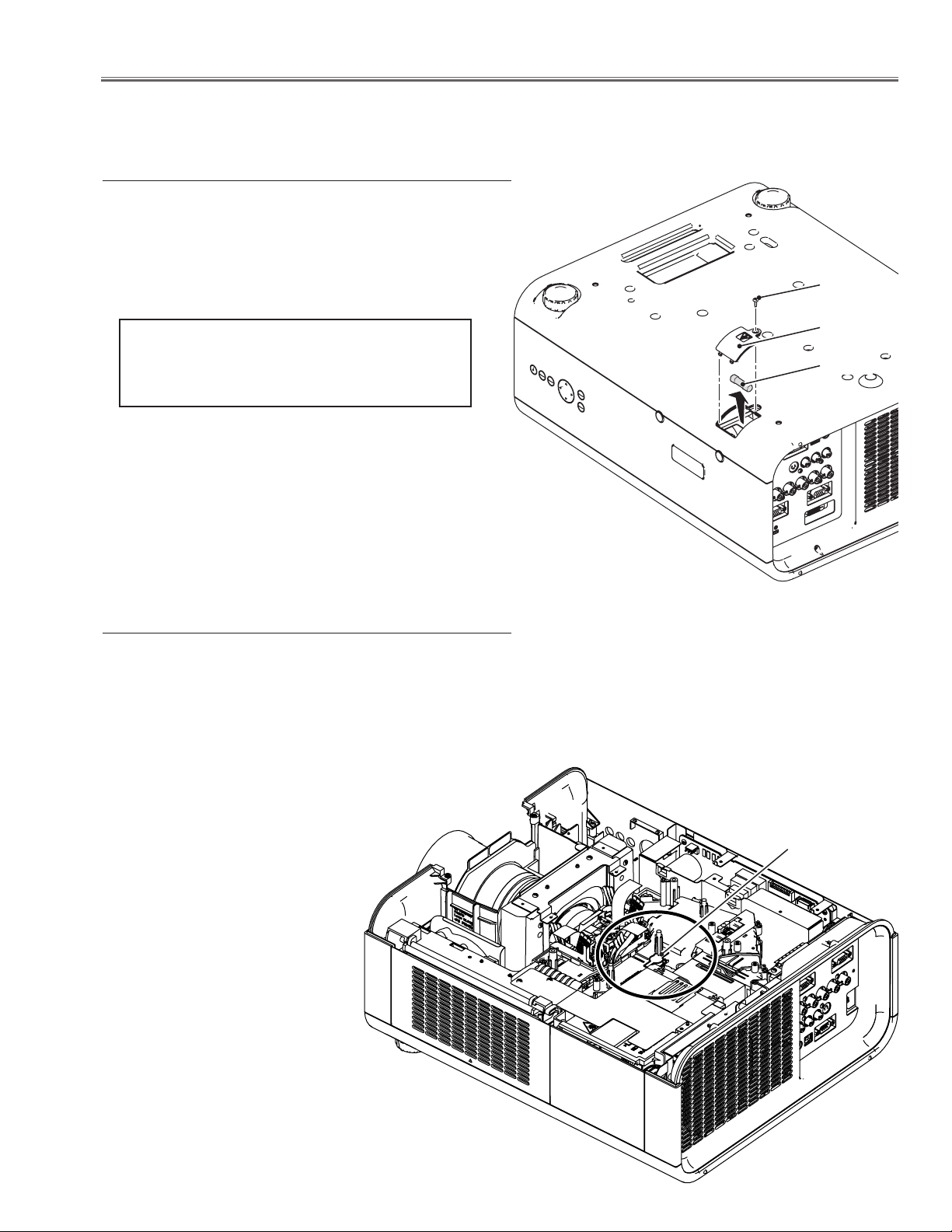
Fuse
A fuse is located inside of the projector. When the POWER
indicator is not lightning, the fuse may be opened. Check
the fuse as following steps.
The fuse should be used with the following type;
Screw
Fuse Part No. : 323 027 2605
TYPE T10AH 250V
LITTEL FUSE INC. TYPE 215010
How to replace the fuse
1. Turn the projector up and down.
2. Remove 1 screw and take the fuse cover off.
3. Remove the fuse from fuse holder on the power board.
To install the fuse, take reversed step in the above.
Thermostat (SW905)
There is the thermostat switch (SW905) inside of the projector to detect the internal temperature rising abnormally. When
the internal temperature reaches near 90˚C, the thermostat
opens to stop the operation of the power supply circuit.
The thermostat will automatically return to normal condition when the internal temperature becomes normal (about
50
˚C)
.
Fuse cover
Fuse
-5-
Thermostat
(SW905)
Page 6
Circuit Protections
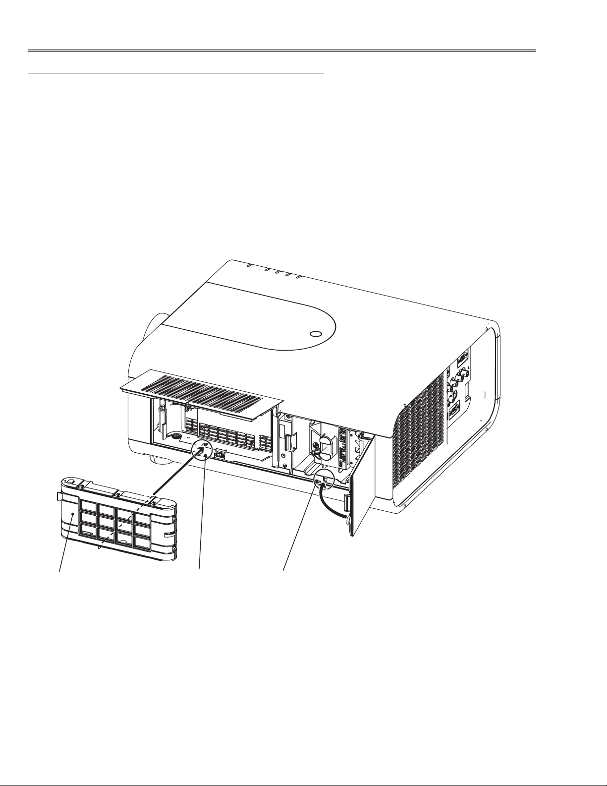
Mechanical sensor switches (SW1891,SW1861)
This projector provides 2 mechanical sensor switches, the one is for
filter cartridge sensor switch (SW1891) and the other one is for lamp
cover sensor switch (SW1861). The filter cartridge sensor switch
detects whether the filter cartridge is installed correctly. If the filter
cartridge is not installed correctly, the projector cannot turn on.
The lamp cover sensor switch detects whether the lamp cover is
closed securely. If lamp cover is opened or not closed completely,
the drive signal to the lamp circuit is cut off. After opening the lamp
cover for replacing the lamp ass’y, place the lamp cover correctly
otherwise the projector cannot turn on.
Filter cartridge
Filter cartridge sensor
switch (SW1891)
Lamp cover sensor
switch (SW1861)
-6-
Page 7
Circuit Protections
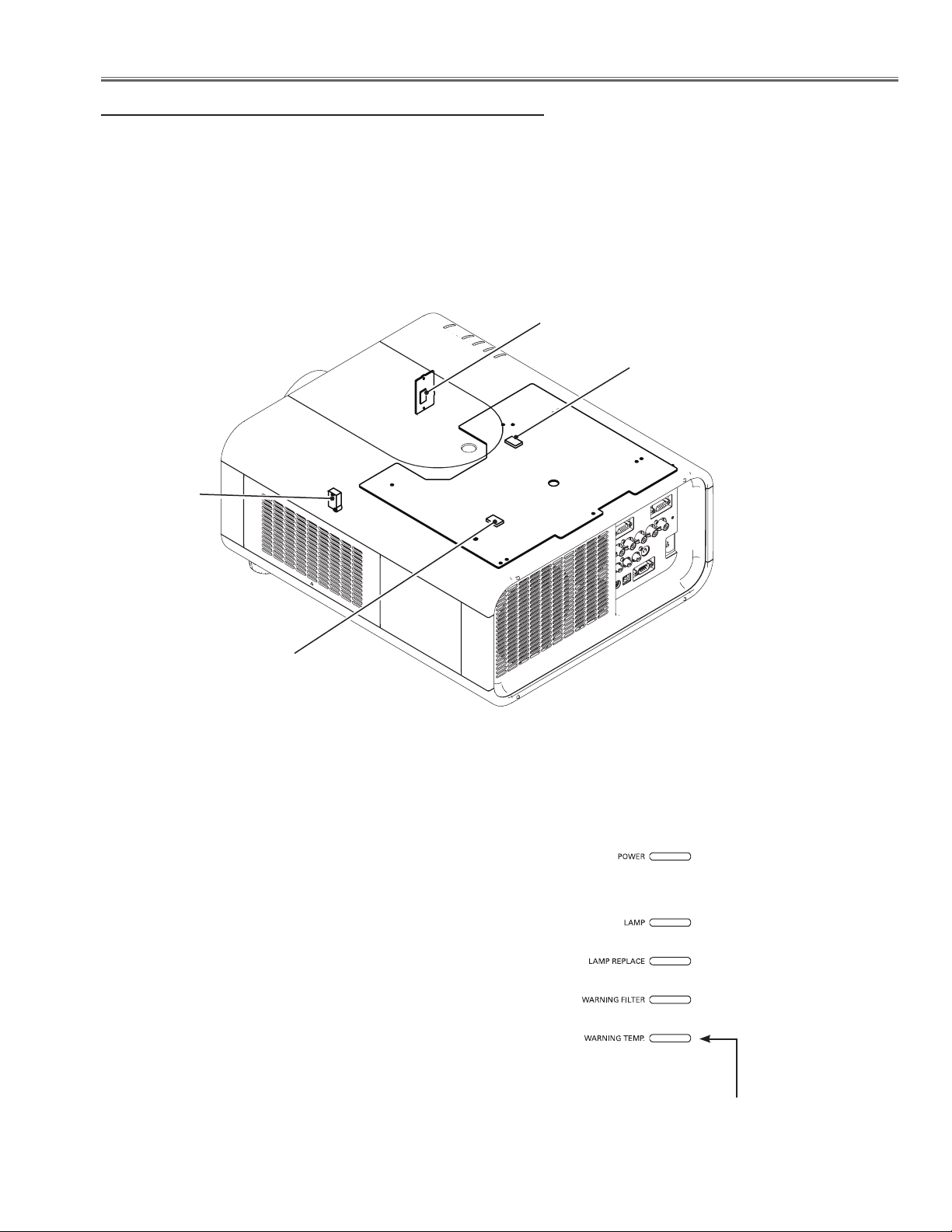
Temperature sensors, wind sensors
The projector provides 3 temperature sensor ICs, 2 sensors on the Main board and 1 sensor on the RC front board,
and 1 wind sensor on the intake duct. The sensor ICs monitor surrounding temperature of the lamp house and panels/prism, and room temperature, and the wind sensor monitors airflow passed through the air filter in the intake
duct.
- Internal temperature sensor A (IC1816) (around the lamp house)
- Internal temperature sensor B (IC1814) (around the panels/prism)
- Room temperature sensor C (IC1692) (around the front cabinet)
- Wind sensor D (S901) (intake duct)
IC1692
IC1814
(Behind)
S901
IC1816
(Behind)
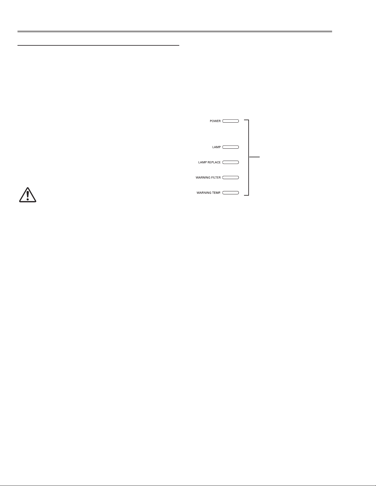
The projector is shut down and the WARNING TEMP. indicator is blinking red.
When the temperature inside the projector reaches a certain
level, the projector will be automatically shut down to protect
the inside of the projector. The POWER indicator is blinking
while the projector is being cooled down. When the projector
has cooled down enough (to its normal operating temperature), it can be turned on again by pressing the ON/STANDBY button.
✔Note:
• The WARNING TEMP. indicator continues to blink even after
the temperature inside the projector returns to normal. When
the projector is turned on again, the WARNING TEMP. indicator stops blinking.
LED indicators
WARNING TEMP.
blinking red
-7-
Page 8
Circuit Protections
Power failure and fan lock detection
The projector provides the detection circuits of the power failure and the fan lock. When the detection circuit detects
an error at the power supply line or at the fan operation circuit, the projector will turn into the standby mode to protect
the other circuits defective.
The projector is shut down; and the LAMP indicator is
lighting and other four indicators are blinking.
When the projector detects an abnormal condition, it will be
automatically shut down to protect the inside of the projector
and all five indicators on the top panel blink. In this case, unplug the AC power cord and plug it, and then turn on the projector once again to verify operation. If the projector cannot
be turned on and these indicators are still blinking, unplug
the AC power cord.
CAUTION
DO NOT LEAVE THE PROJECTOR WITH THE
AC POWER CORD CONNECTED UNDER AN ABNORMAL CONDITION. IT MAY RESULT IN FIRE
OR ELECTRIC SHOCK.
LED indicators
LAMP indicator lights on
and other four indicators
blink
-8-
Page 9
Maintenance
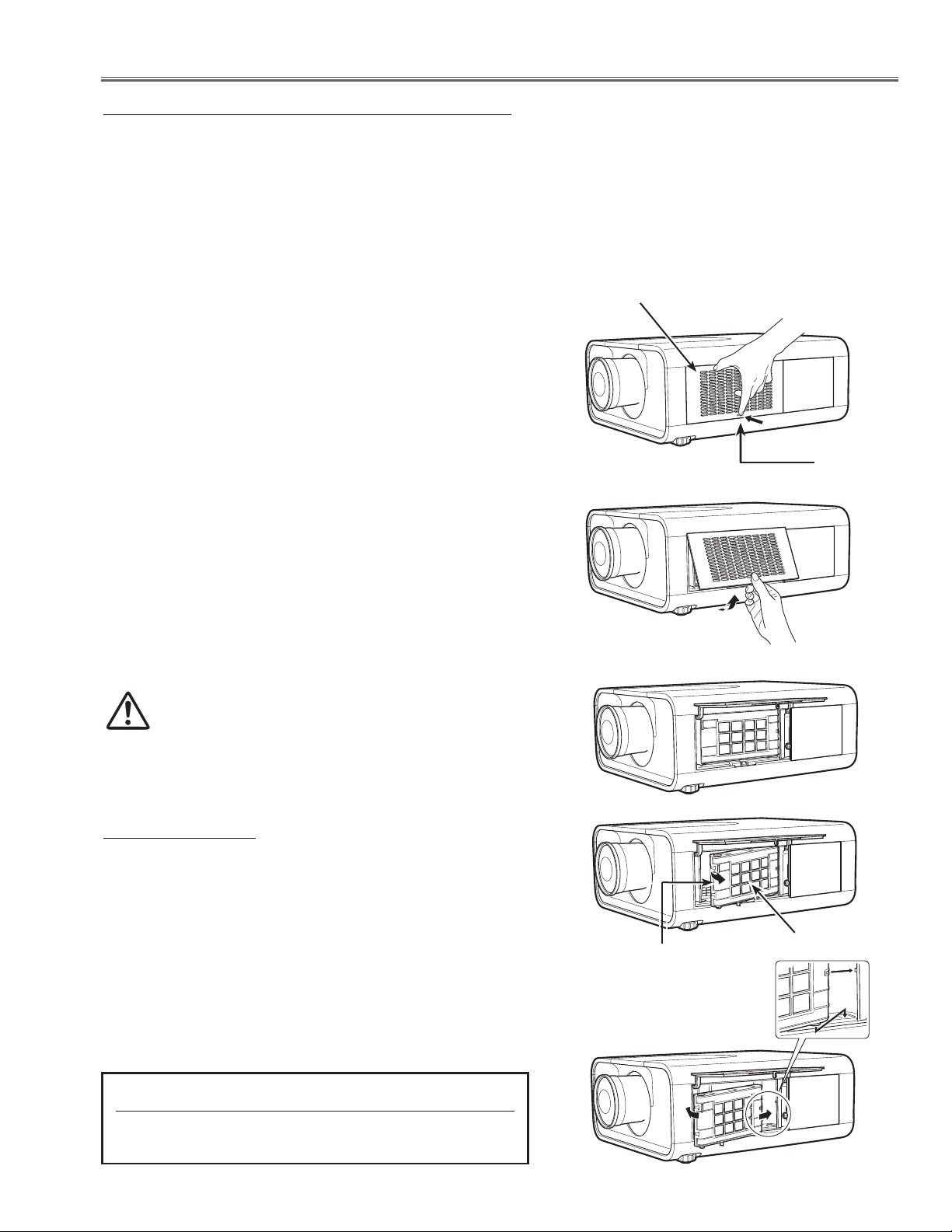
Replacing the Filter Cartridge
Filter prevents dust from accumulating on the optical elements inside the projector. Should the filter becomes clogged
with dust particles, it will reduce cooling fans’ effectiveness and may result in internal heat buildup and adversely
affect the life of the projector. This projector has an electrically operated filter which helps you to replace the filter
easily. The projector monitors the condition of the filter at all time and replaces a filter with a new one automatically
when it detects the clogging.
If the projector detects that the filter is clogged and no scroll is left in the filter cartridge, a Filter cartridge replacement
icon appears on the screen and the WARNING FILTER indicator on the top panel lights up. When you see this icon,
replace the filter cartridge and reset the Filter counter and the Scroll counter.
Filter cover
Turn off the projector, and unplug the AC power cord
1
from the AC outlet.
First, clean up the dust on the projector and around the
2
air vents.
Press d on the filter cover to release the latch and open
3
the filter cover.
Pull out the filter cartridge. When taking out the filter
4
cartridge, put your finger on the filter cartridge’s tab and
then pull.
Put the new one back into the position and close the
5
filter cover. Make sure that the filter cartridge is properly
and fully inserted.
Connect the AC power cord to the projector and turn
6
on the projector.
Reset the filter counter and the scroll counter.
7
CAUTION
Do not operate the projector with the filter removed.
Dust may accumulate on the optical elements degrading the picture quality.
Do not put anything into the air vents. Doing so may
result in malfunction of the projector.
RECOMMENDATION
We recommend avoiding dusty/smoky environments
when operating the projector. Usage in these environments may cause a poor image quality.
Latch
When using the projector under dusty or smoky conditions,
dust may accumulate on a lens, liquid crystal panels, or optical elements inside the projector. Such condition may degrade the quality of the projected image.
When the symptoms above are noticed, contact your authorized dealer or service station for proper cleaning.
ORDER REPLACEMENT FILTER CARTRIDGE
Service Parts No.: 610 334 3747
-9-
Tab
Filter cartridge
Page 10
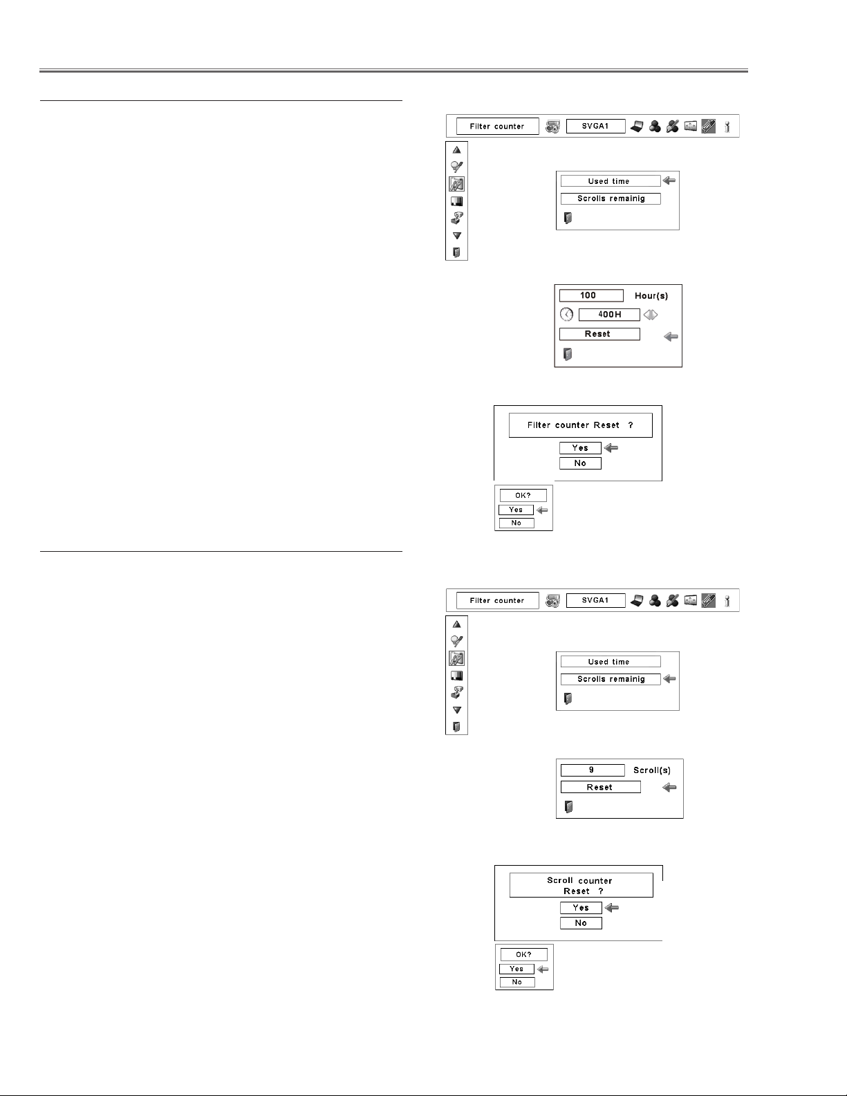
Resetting the Filter Counter
Be sure to reset the Filter counter after replacing the filter and
the filter cartridge.
Press the MENU button to display the On-Screen Menu.
1
Use the Point 7 8 buttons to move the red frame point-
er to the Setting Menu icon.
Use the Point ed buttons to move the red frame point-
2
er to Filter counter and then press the SELECT button.
A dialog box appears showing the Used time option and
the Scrolls remaining option. Use the Point ed buttons
to select Used time.
Used time shows the total accumulated time of the filter
3
use, a timer setting option, and the Reset option. Select
Reset and the “Filter counter Reset?” appears. Select
[Yes] to continue.
Another confirmation dialog box appears, select [Yes]
4
to reset the Filter counter.
Filter counter
Select “Used time” and the dialogue box below appears.
Select Reset and the “Filter
counter Reset?” appears.
Select [Yes],
then another
confirmation
box appears.
Resetting the Scroll Counter
Be sure to reset the Scroll counter after replacing the filter
cartridge.
Press the MENU button to display the On-Screen Menu.
1
Use the Point 7 8 buttons to move the red frame pointer to the Setting Menu icon.
Use the Point ed buttons to move the red frame point-
2
er to Filter counter and then press the SELECT button.
A dialog box appears showing the Used time option and
the Scrolls remaining option. Use the Point ed buttons
to select Scroll(s) remaining.
Scroll(s) remaining shows the number of the remain-
3
ing scrolls and the Reset option. Select Reset and the
“Scroll counter Reset?” appears. Select [Yes] to continue.
Another confirmation dialog box appears, select [Yes]
4
to reset the Scroll counter.
Select [Yes] again to reset
the Filter counter.
Scroll counter
Select “Scrolls remaining” and
the dialogue box below appears.
Select Reset and the “Scroll
counter Reset?” appears.
Select [Yes],
then another
confirmation
box appears.
-10-
Select [Yes] again to reset
the Scroll counter.
Page 11
Maintenance
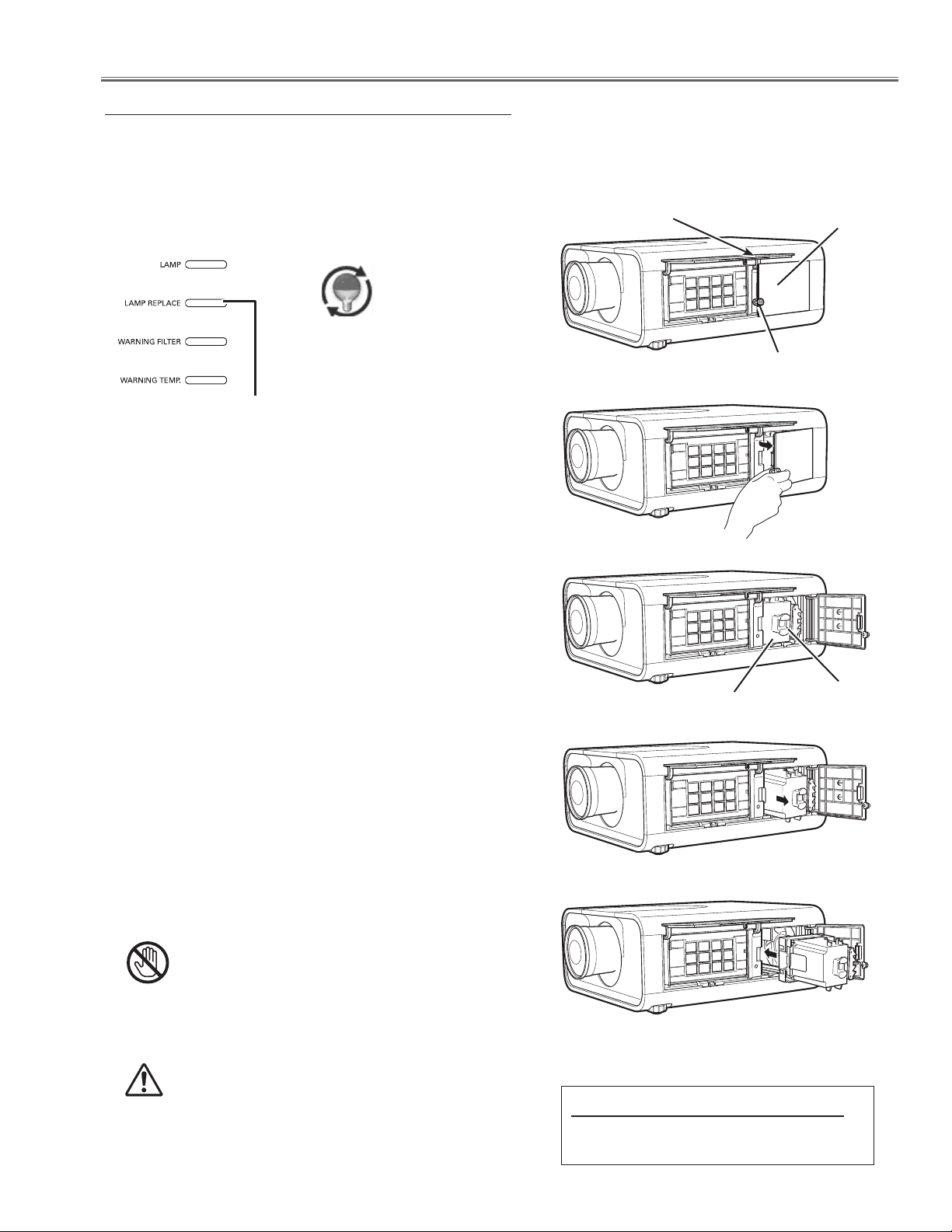
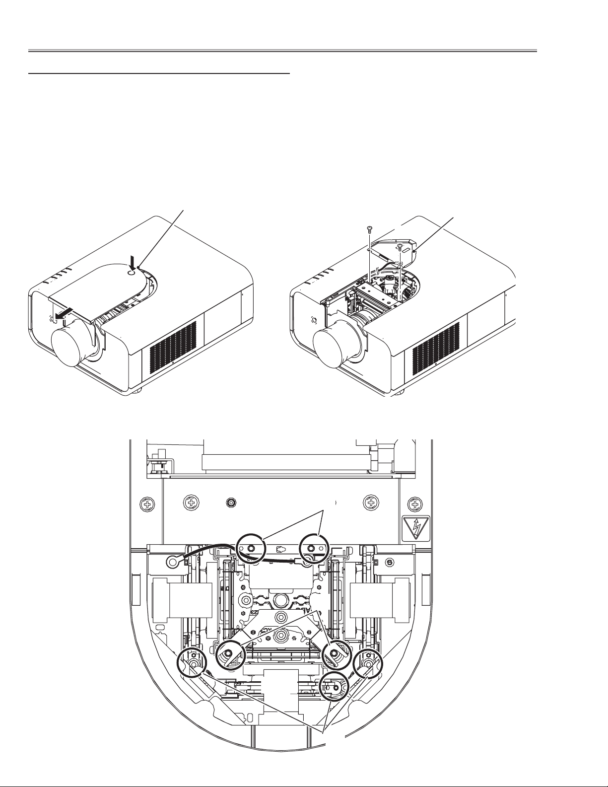
Lamp Replacement
When the projection lamp of the projector reaches its end of life, the Lamp replacement icon appears on the screen
and LAMP REPLACE indicator lights orange. Replace the lamp with a new one promptly. The timing when the LAMP
REPLACE indicator should light is depending on the lamp mode.
Top Panel
Lamp replacement icon
LAMP REPLACE indicator
Follow these steps to replace the lamp.
Turn off the projector and unplug the AC power cord.
1
Let the projector to cool for at least 45 minutes.
Open the filter cover.
2
Filter cover
Lamp cover
Screw
Loosen the screw and open the lamp cover and pull
3
out the lamp by using the built in handle.
Replace the lamp with a new one. Make sure that
4
the lamp is properly and fully inserted.
Close the lamp cover and secure the screw, and
5
close the filter cover.
Connect the AC power cord to the projector and turn on
6
the projector.
Reset the Lamp replacement counter
7
Note:
• Be sure to insert the lamp in the correct direction.
• Do not reset the Lamp replacement counter when the pro
jection lamp is not replaced.
CAUTION
Allow a projector to cool for at least 45 minutes
before you open the lamp cover. The inside of the
projector can become very hot.
Lamp
-
Handle
CAUTION
For continued safety, replace with a lamp of the
same type. Do not drop the lamp or touch the glass
bulb! The glass can shatter and may cause injury.
ORDER REPLACEMENT LAMP
Type No. POA-LMP108
Service Parts No. 610 334 2788
-11-
Page 12
Counter
Projector 500 H
Lamp
Normal 200 H
Eco 300 H
Corresponding value 600 H
Maintenance
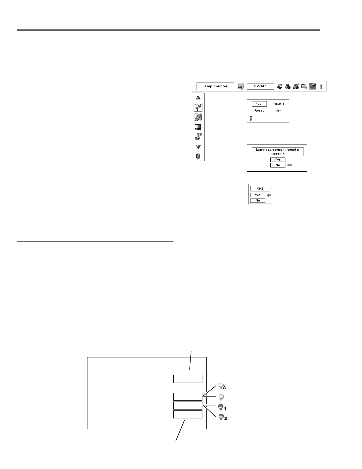
Resetting the Lamp Counter
Be sure to reset the Lamp counter after the lamp is replaced. When the Lamp counter is reset, the LAMP REPLACE indicator stops lighting and the Lamp replacement icon disappears.
Press the MENU button to display the On-Screen Menu.
1
Use the Point 7 8 buttons to move the red frame pointer
to the Setting Menu icon
Use the Point ed buttons to move the red frame pointer
2
to Lamp counter and then press the SELECT button. A
dialog box appears showing the total accumulated time
of the lamp usage and the reset option. Select Reset
and the “Lamp replacement counter Reset?” appears.
Select [Yes] to continue.
Another confirmation dialog box appears and select
3
[Yes] to reset the Lamp replacement counter.
Note:
• Do not reset the Lamp counter without replacing the lamp. Be
sure to reset the Lamp replacement counter only after replacing
the lamp.
How to check Lamp Used Time
Lamp counter
Select Reset and the “Lamp
replacement counter Reset?”
appears.
Select [Yes], then another
confirmation box appears.
Select [Yes] again
to reset the lamp
counter.
The LAMP REPLACE indicator will light yellow when the total lamp used time (Corresponding value) reaches 3,000
hours. This is to indicate that lamp replacement is required.
The total lamp used time is calculated by using the below expression,
Total lamp used time (Corresponding value) = Teco + (Tnormal x 1.5)
Teco: used time in the Eco mode
Tnormal : used time in the Normal mode
You can check the lamp used time following to the below procedure.
1 Press and hold the ON/STAND-BY button on the projector for more than 20 seconds.
2 The projector used time and lamp used time will be displayed on the screen briefly as follows.
Projector used time
Lamp mode
Total lamp used time
-12-
Page 13

Maintenance
Cleaning
After long periods of use, dust and other particles will accumulate on the LCD panel, prism, mirror, polarized glass,
lens, etc., causing the picture to darken or color to blur. If this occurs, clean the inside of optical unit.
Remove dust and other particles using air spray. If dirt cannot be removed by air spray, disassemble and clean the
optical unit.
Cleaning with air spray
1. Remove the cabinet top following to “Mechanical Disassembly”.
2. Clean up the LCD panel and polarizing plate by using
the air spray from the cabinet top opening.
Caution:
Use a commercial (inert gas) air spray designed for
cleaning camera and computer equipment. Use a resinbased nozzle only. Be vary careful not to damage optical
parts with the nozzle tip. Never use any kind of cleanser
on the unit. Also, never use abrasive materials on the
unit as this may cause irreparable damage.
Disassembly Cleaning
Disassembly cleaning method should only be performed
when the unit is considerable dirty and cannot be sufficiently cleaned by air spraying alone.
Be sure to readjust the optical system after performing disassembly cleaning.
1. Remove the cabinet top and main units following to
“Mechanical Disassembly”.
2. Remove the optical base top following to “Optical
Unit Disassembly”. If the LCD panel needs cleaning,
remove the LCD panel unit following to “LCD panel
replacement”.
3. Clean the optical parts with a soft cloth. Clean extremely dirty areas using a cloth moistened with alcohol.
Caution:
The surface of the optical components consists of multiple dielectric layers with varying degrees of refraction.
Never use organic solvents (thinner, etc.) or any kind of
cleanser on these components.
Since the LCD panel is equipped with an electronic circuit, never use any liquids (water, etc.) to clean the unit.
Use of liquid may cause the unit to malfunction.
-13-
Page 14
Maintenance
Quick maintenance
This projector provides a cabinet front cover on the cabinet top to enhance the service maintenance. This enables
service personnel to align the optical adjustment or replace the optical parts without disassembly the cabinet top.
1. Press and hold the release button the cabinet front cover and slide the cover frontward to take it off.
2. Remove 2 screws A on the prism shield cover and take prism shield cover off.
3. Loosen 4 screws B and take the LCD Panel/Prism ass'y upward off.
4. Remove 1 screw C on each stopper of the optical filter ass'y and take the optical filter ass'y upward off.
See chapter "Optical Parts Disassembly" for further information of optical parts disassembly.
Release button
A
Prism shield cover
A
Green
-14-
B
B
C
Page 15

Security Function Notice
This projector provides security functions such as "Key lock", "PIN code lock" and "Logo PIN code lock". When the
projector has set these security function on, you are required to enter correct PIN code to use the projector. If you
do not know the correct PIN code to the projector, the projector can no longer be operated or started. In this case,
you must reset those function first according to the resetting procedure described below and then check up on the
projector.
Function Description
Locks operation of the side control or the remote control.
Key lock
PIN code lock
Logo PIN code lock
If the Key lock is enabled with side control lock, the
projector can no longer be started.
Initial setting: Key lock function is disabled
Prevents the projector from being operated by an unauthorized person.
Initial code: “1234”
Prevents an unauthorized person for changing the
start-up logo on the screen.
Initial code: “4321”
Resetting procedure
1 Disconnect the AC power cord from the AC outlet.
2 As pressing the SELECT button on the projector, connect the AC power cord into an AC outlet again. Keep
pressing the SELECT button until the POWER indicator lights continuously.
This is complete the resetting of the security function. The PIN code lock and Logo PIN code lock are reset
as the initial PIN code at the factory and the Key lock function is disabled.
Please refer to the owner's manual for further information of the security functions.
-15-
Page 16
Mechanical Disassembly
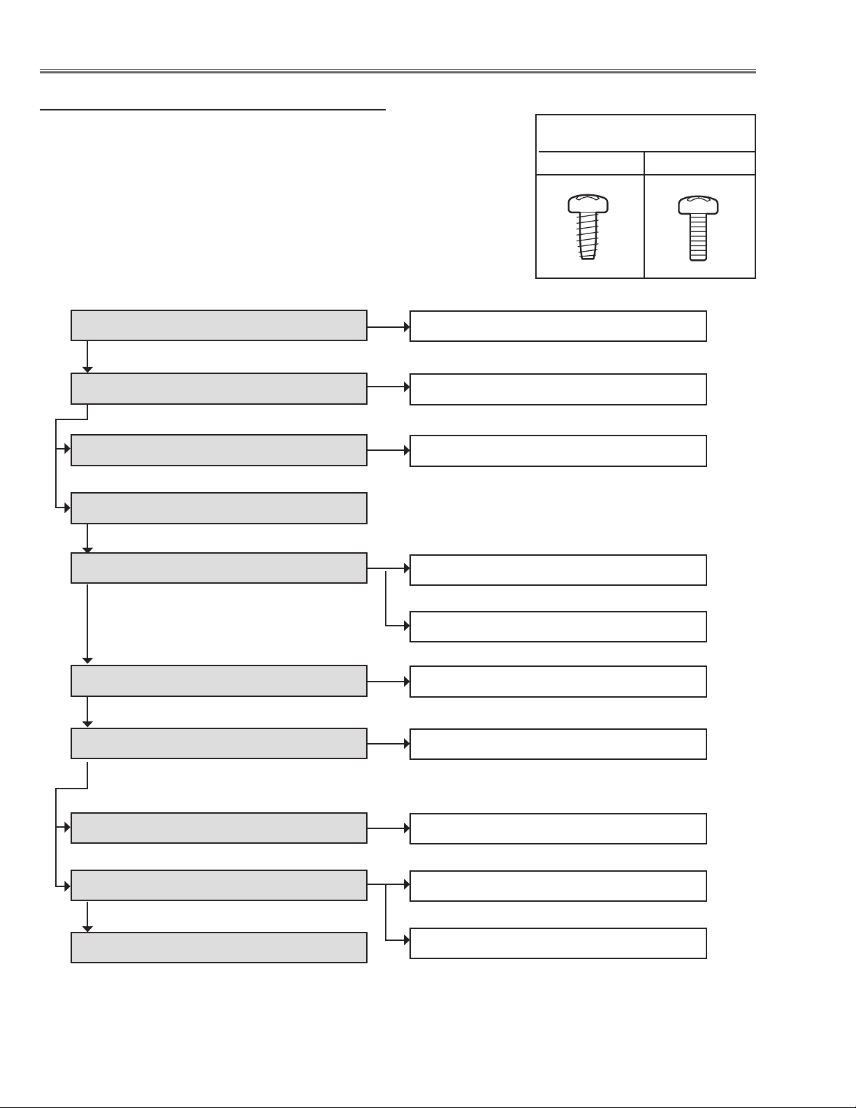
Mechanical disassembly flow chart
Mechanical disassembly should be made by following procedures chart.
Following steps show the basic procedures, therefore unnecessary step may
be ignored.
Caution:
The parts and screws should be placed exactly the same position as the original otherwise it may cause loss of performance and product safety.
The wiring method of the leads and ferrite cores should be returned exactly the
same state as the original, otherwise it may cause lose of performance and
product safety.
Screws Expression
(Type Diameter x Length) mm
T type M Type
1 Cabinet front cover removal
2 Cabinet top removal
3 Control ass'y and filter cover removal
4 Main board removal
5 Cabinet back & lamp cover removal
6 Power box removal
1-1 Cabinet front disassembly
2-1 LED board removal
3-1 Control board fan (FN907) disassembly
5-1 AV board removal
5-2 Fans (FN904, FN905, FN906) removal
6-1 Power box disassembly
7 Optical unit removal
8 Cabinet front & ballast box removal
9 Filter box removal
10 Fan (FN902, FN903) & duct removal
7-1 Lens shift motor ass'y removal
8-1 Ballast box disassembly
9-1 Filter box and fan (FN901) disassembly-
9-2 Filter box disassembly-2
-16-
1
Page 17
Mechanical Disassembly
Mechanical disassembly
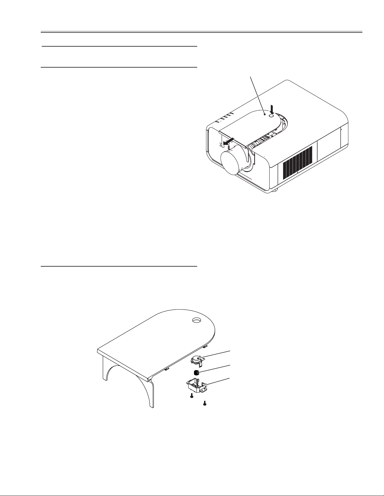
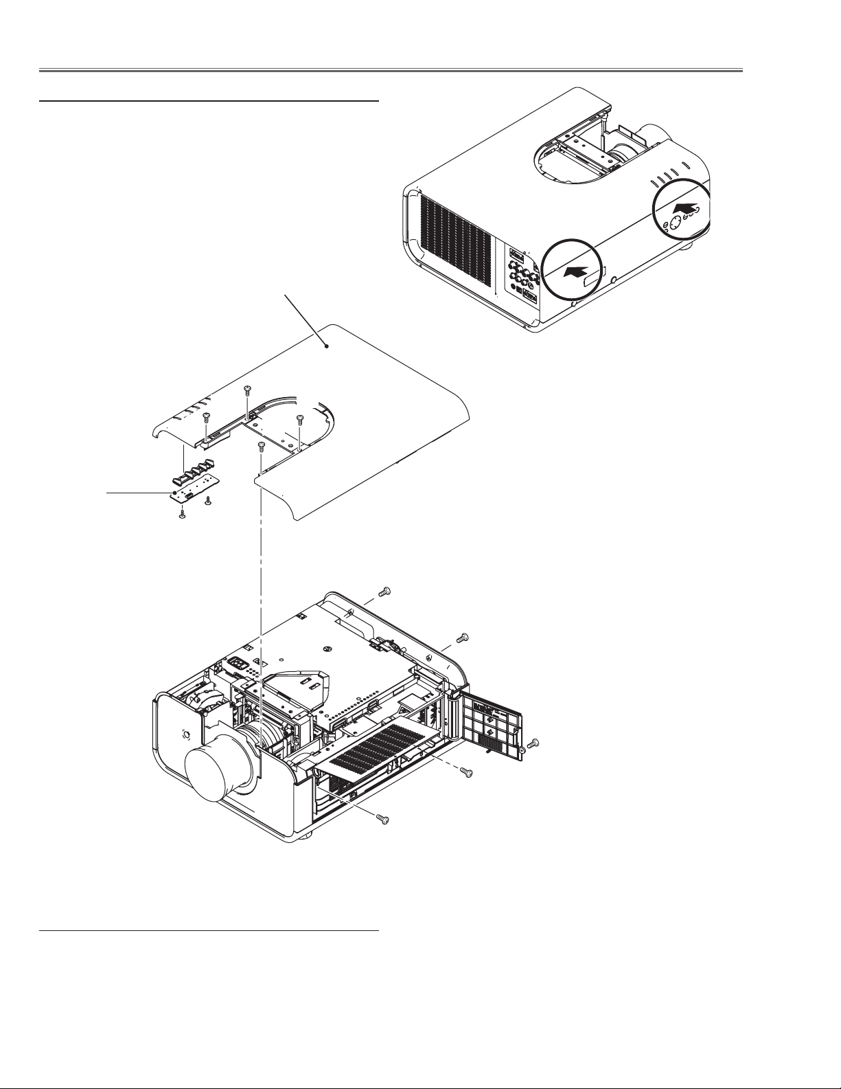
1 Cabinet front cover removal
1 Press the release button and slide the lamp cover to
the arrow direction and remove it.
Release Button
1-1 Cabinet front cover disassembly
1 Remove 2 screws A(T3x8) and take the release button,
button holder and spring off.
A
Fig. 1-1
Release button
Spring
Button holder
A
-17-
Page 18
Mechanical Disassembly
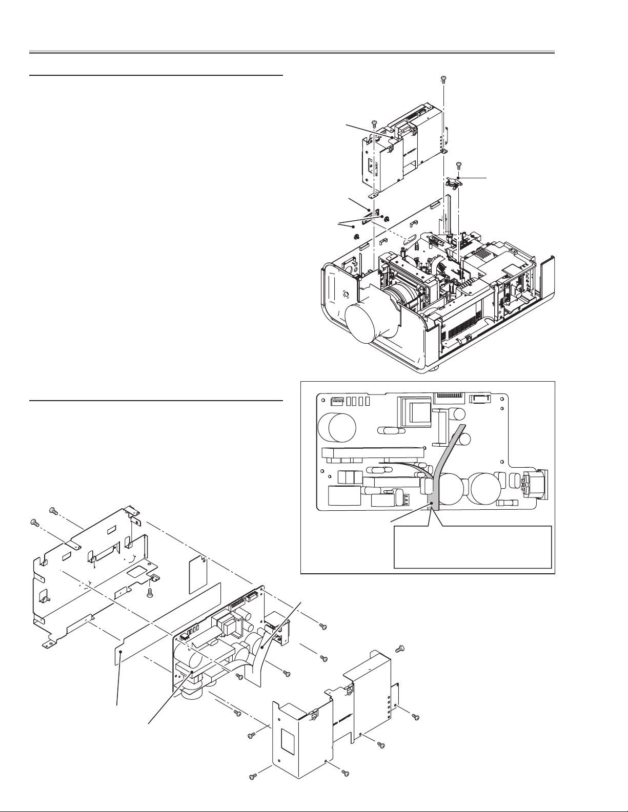
2 Cabinet top removal
1 Open the filter cover and remove 1 screw A (M3x8).
2 Remove 1 screw B (M3x8) and open the lamp cover
and remove 1 screw C (M3x8).
3 Remove 4 screws D (M3x8) on the cabinet top and 2
screws E (M3x8) on the cabinet back.
4 Release the hooks by pressing the side part of cabinet
bottom indicated with the arrows and take the cabinet
top off.
Cabinet top
D
D
D
D
Press here to unhook
LED board
F
F
E
E
B
C
A
2-1 LED board removal
1 Remove 2 screws F (M3x8) and take the LED board
and LED holder off.
Fig. 1-2
-18-
Page 19
Mechanical Disassembly
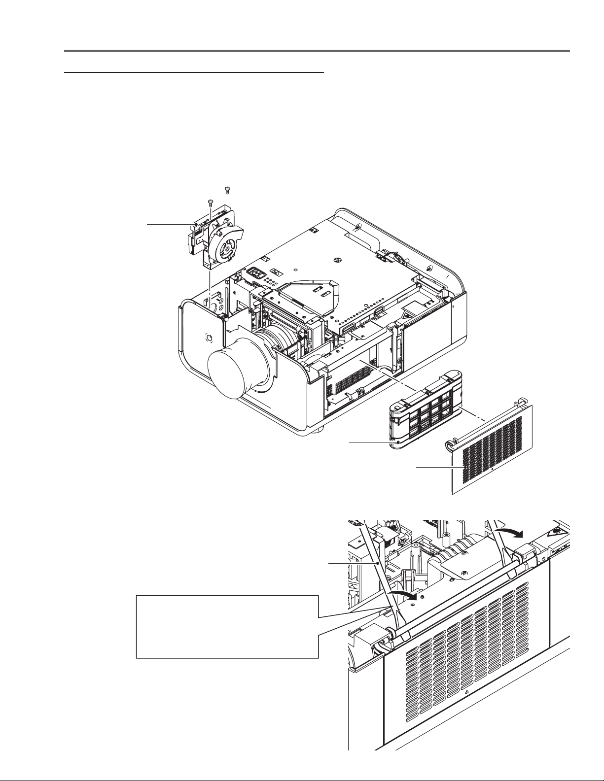
3 Control board ass’y and covers removal
1 Remove 2 screws A (T3x8) and take the control board &
fan ass’y upward off.
2 Open the filter cover and take the filter cartridge off.
3 Remove the filter cover off by using a flat screw driver as
shown in the figure.
A
A
Control board &
fan(FN907) ass'y
Filter cartridge
Flat screwdriver
Turn the flat screwdriver in the arrow
direction to unhook the filter cover's
hinges.
Note: Be careful not to scratch the filter
cover and holder.
Filter cover
-19-
Page 20
Mechanical Disassembly
3-1 Control board and fan (FN907) disassembly
1 Remove 2 screws B (M3x6) and take the control board/
button holder off
2 Unhook 4 hooks C on the button holder and take the con-
trol board off.
3 Remove 2 screws D (M3x10) and take fan (FN907) off.
C
Control buttons
C
Control board
4 Main board removal
1 Remove 2 screws A (M3x6) and take the prism shield
cover top off.
2 Remove 6 screws B (M3x6) and take the main shield cover
top off.
3 Remove 1 screw C (M3x6) and take the main board off.
4 Remove 2 screws D (M3x6) and take the main shield cov-
er bottom off.
B
B
FN907
D
B
B
B
B
B
B
A
A
-20-
C
Main
board
D
D
Page 21
Mechanical Disassembly
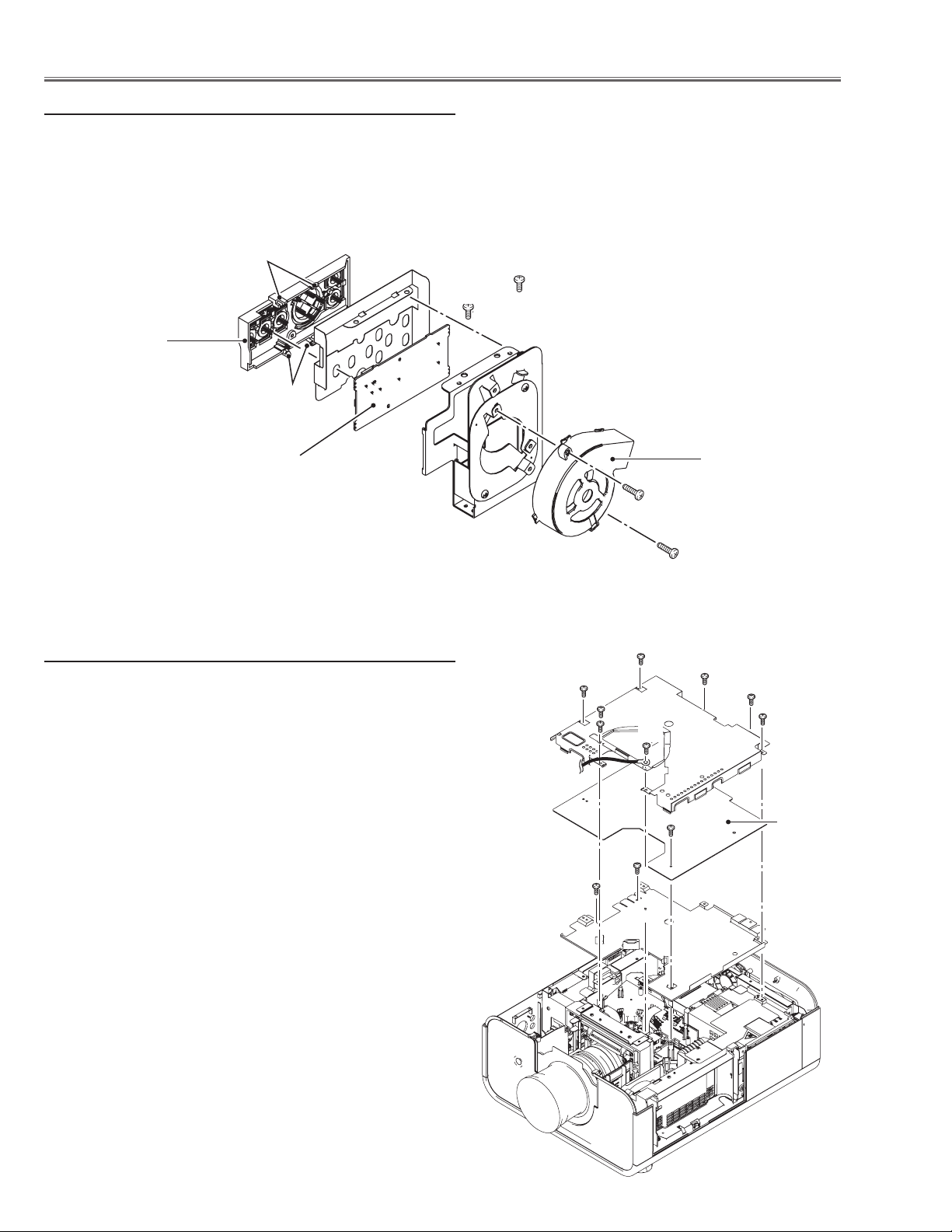
5 Cabinet back ass’y removal
1 Remove 3 screws A (T3x8) and 1 screw B (M3x6) and
take the cabinet back ass’y upward off.
A
A
B
A
Lamp cover
5-1 AV board removal
1 Remove 5 screws D (T3x8) and 4 screws E (T3x10-
black) and take the AV board off.
E
D
AV board
5-2 Fans (FN904, FN905, FN906) removal
1 Remove 6 screws F (T3x8) and take the fans (FN904,
FN905, FN906) off.
FN905
FN906
FN904
F
-21-
Page 22
Mechanical Disassembly
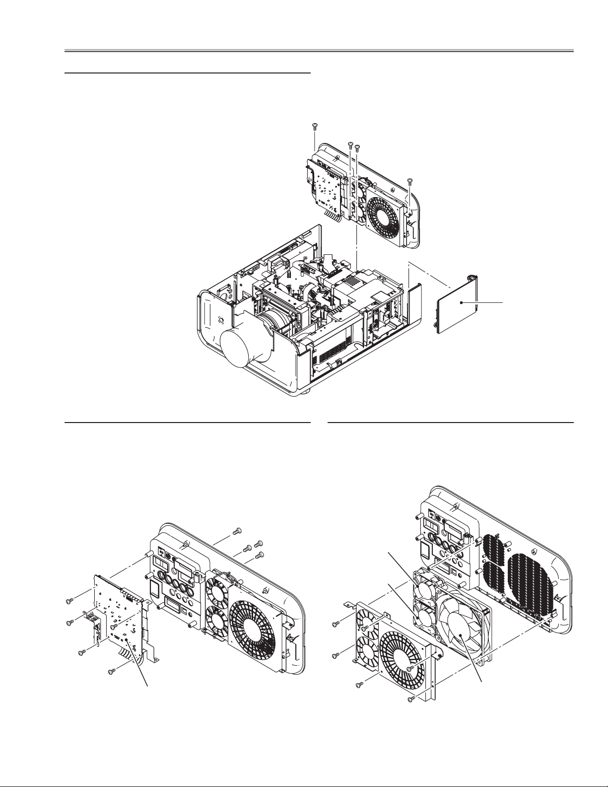
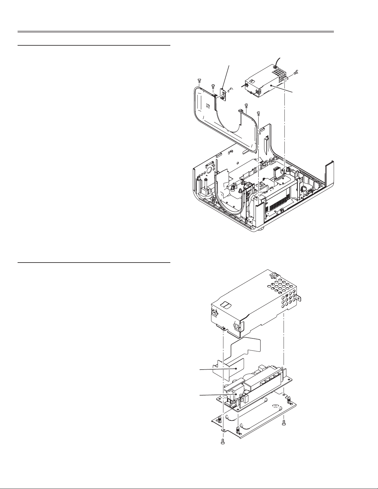
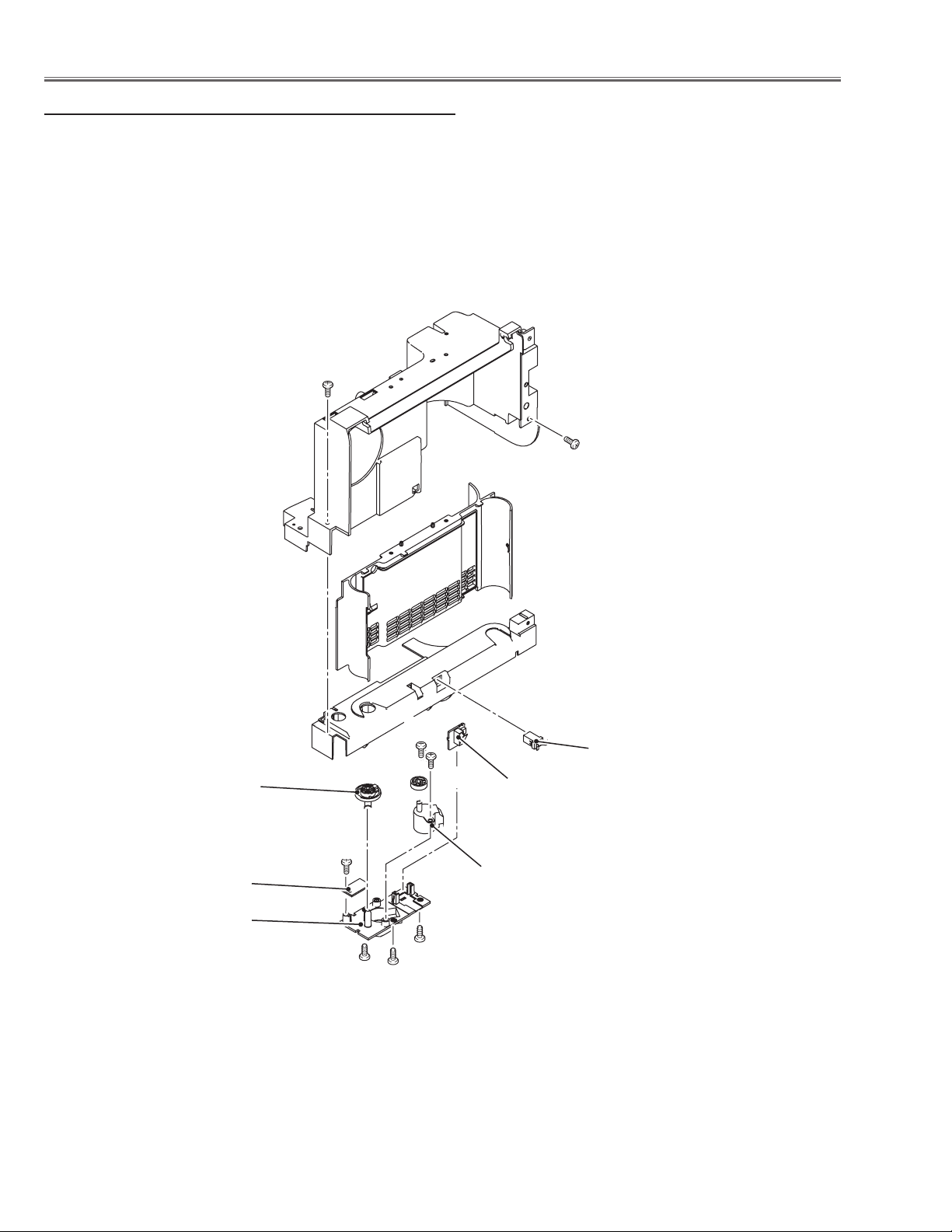
6 Power Box removal
1 Remove the 3 covers A and B on the cabinet.
2 Remove 1 screw C (T3x12) and take thermal switch
(SW905) off
3 Disconnect the socket D (K6B) on the power board.
4 Remove 2 screws E (M4x8) and take the power box
upward off.
E
E
D
C
B
Thermal switch
(SW905)
A
6-1 Power box disassembly
1 Remove 6 screws F (M3x6) and take the power box
cover off.
2 Remove 5 screws G (M3x6), 1 screw H (M4x8), 2
screws J (T3x5) and take the power board off.
J
H
G
Isolation sheet
Power board
G
F
Isolation sheet
Note:
The isolation sheet must be placed
as shown in the figure above.
Isolation sheet
G
F
G
G
F
F
F
-22-
F
Page 23
Mechanical Disassembly
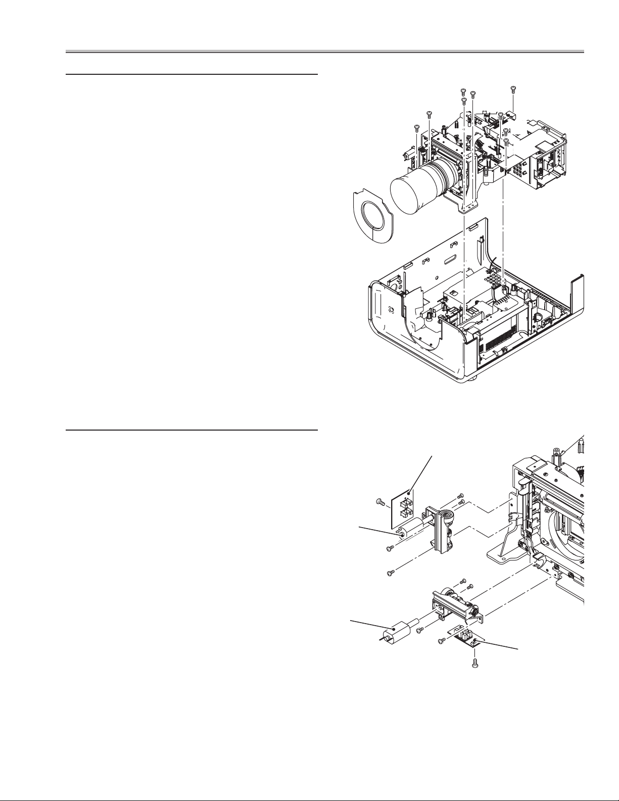
7 Optical unit removal
1 Remove 7 screws A (T4x12) and 2 screws B (T3x8),
disconnect ballast socket and take the optical unit upward off.
A
A
A
A
A
A
B
B
7-1 Lens shift motor ass’y removal
1 Remove 2 screws B (M3x6) and take the lens shift mo-
tor ass’y off.
2 Remove 1 screw C (T3x6) and take the lens shift sen-
sor board off.
3 Remove 2 screws D (T2x4) and take the lens shift mo-
tor off
Lens shift motor
Lens shift motor
Sensor board
D
C
B
B
B
B
D
Sensor board
C
-23-
Page 24
Mechanical Disassembly
8 Cabinet front and ballast box removal
1 Remove 4 screws A (T3x8) and take the cabinet front
upward off.
2 Remove 1 screw B (T3x8) and take the RC front board
off.
3 Remove 1 screw C (M4x8) and pull the ballast box
backward and remove it off.
RC front board
A
C
A
B
Ballast box
A
A
8-1 Ballast box disassembly
1 Remove 2 screws D (M3x6) and take the shield case
top off
2 Remove ballast board from the shield case bottom.
Isolation sheet
Ballast board
D
-24-
D
Page 25
Mechanical Disassembly
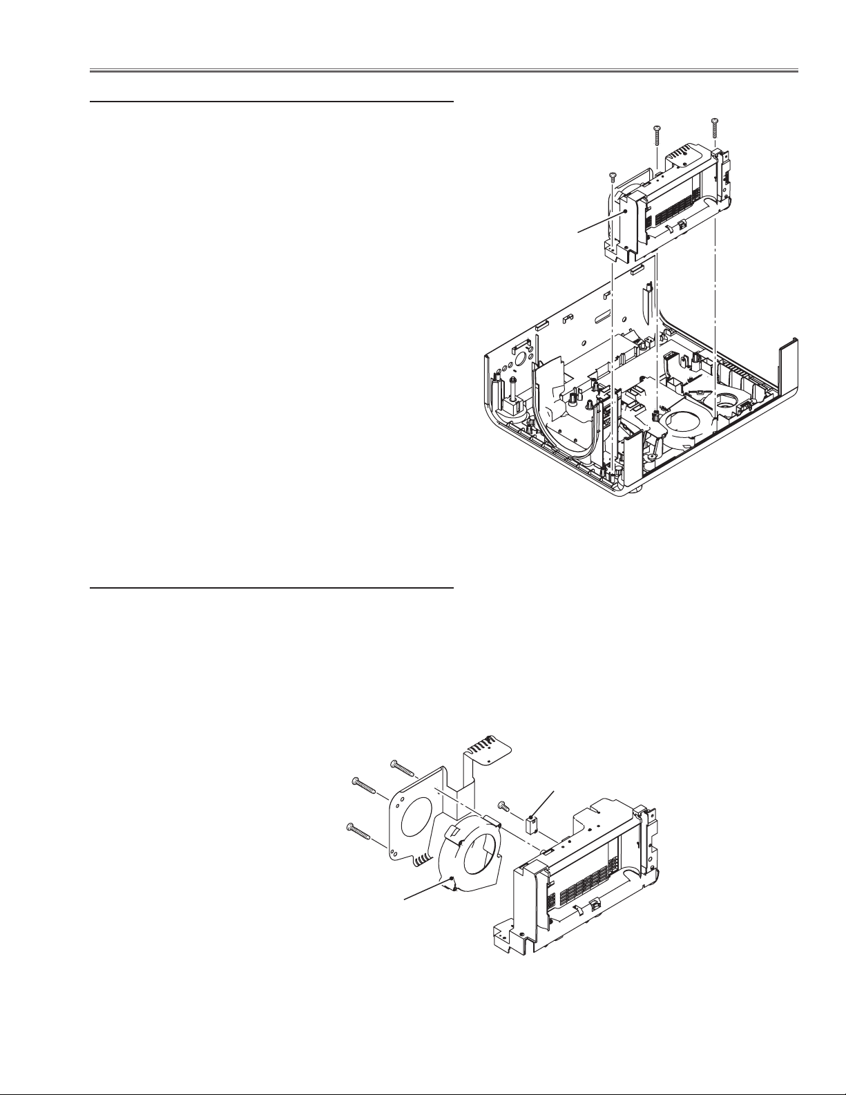
9 Filter box removal
1 Remove 1 screws A (T3x8), 2 screws B (T4x40) and take
filter box upward off.
Filter box
B
B
A
9-1 Filter box and fan (FN901) disassembly-1
1 Remove 3 screws C (T4x35), and take fan (FN901) and
holder off.
2 Remove 1 screw D (T3x14) and take the wind sensor
(S901) off.
C
C
C
FN901
D
S901
-25-
Page 26
Mechanical Disassembly
9-2 Filter box disassembly-2
1 Remove 2 screws E (T3x8) and take the filter cover off.
2 Take the filter cover latch off by pulling it.
3 Remove 3 screws F (T3x8) and take the filter bottom cover
off.
4 Take the filter switch board off, and remove 1 screw G and
take the filter round sensor board off.
5 Remove 2 screws H (T4x8) and filter motor off.
E
E
Filter shaft
holder
Filter round
sensor board
Filter bottom
cover
G
H
Latch
H
Filter switch
board
Filter motor
F
F
F
-26-
Page 27
Mechanical Disassembly
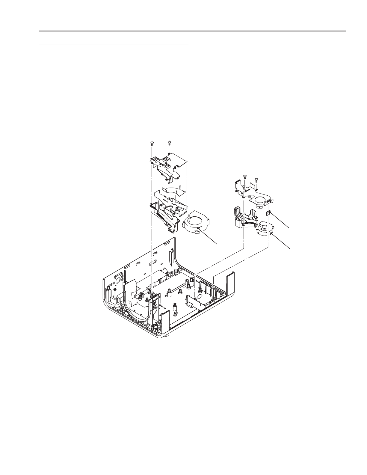
10 Fans (FN902, FN903) and duct removal
1 Remove fan (FN902) upward off.
2 Remove 2 screws A (T3x8) and take duct (prism) up-
ward off.
3 Remove 3 screws B (3x8) and take duct (PBS) upward
off.
4 Remove lamp cover switch board upward off.
5 Remove fan (FN903) upward off.
A
A
B
B
Lamp cover
switch board
FN902
FN903
-27-
Page 28
Optical Parts Disassembly
Disassembly requires a 2.0mm or 2.5mm hex wrench and a slot screwdriver.
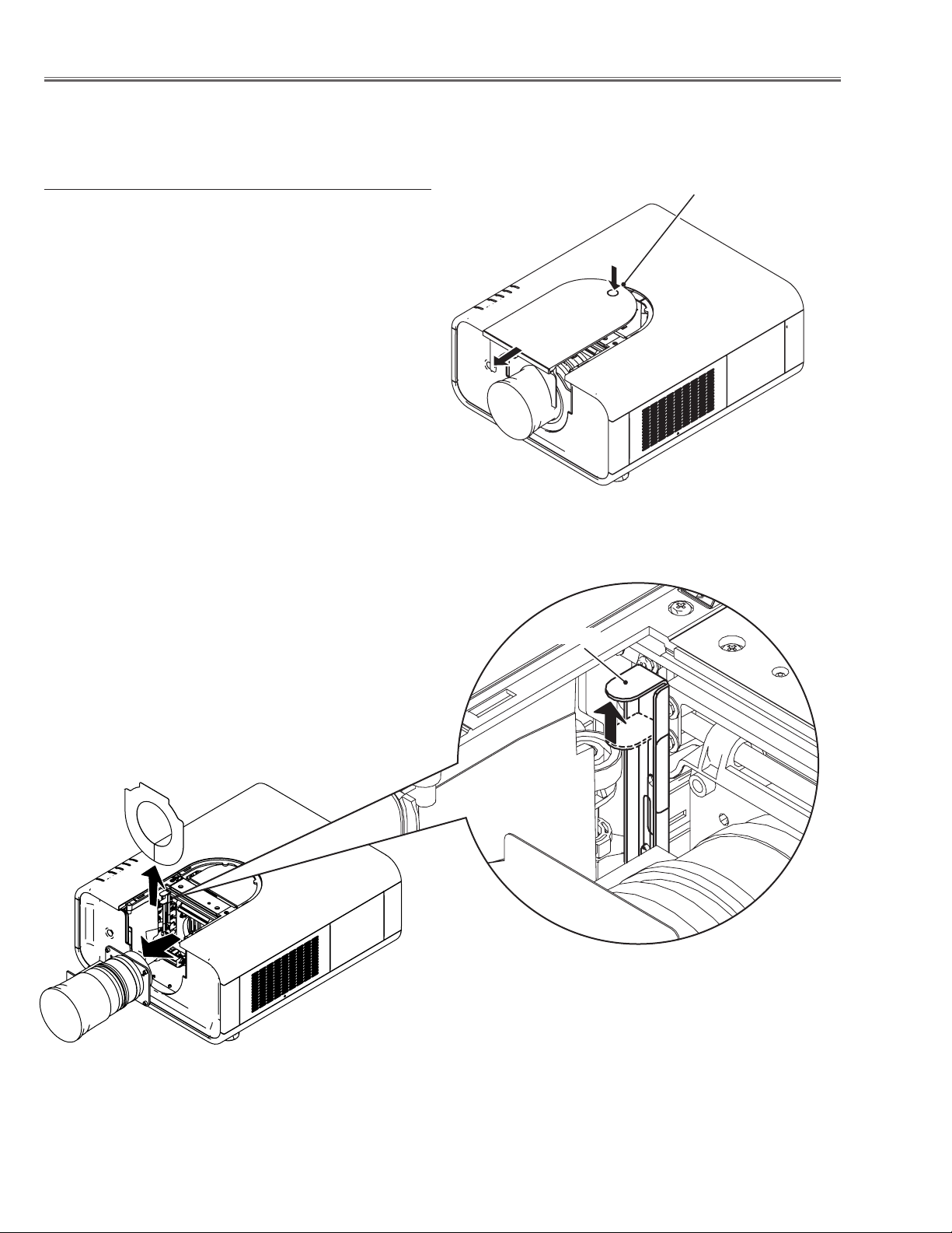
1 Projection lens removal
1 Shift the Projection lens to the low end by the lens shift
function.
2. Press and hold the release button on the cabinet front
cover and slide it in the arrow direction as shown in the
figure and open it.
3 Slide the lens lock lever A on the projector to “UN-
LOCK” (UPPER) position and remove the Projection
Lens ass’y off.
Note : When making unlocking, attach your hand to pre-
vent the lens fall.
Release button
Lever A
-28-
Page 29
Optical Parts Disassembly
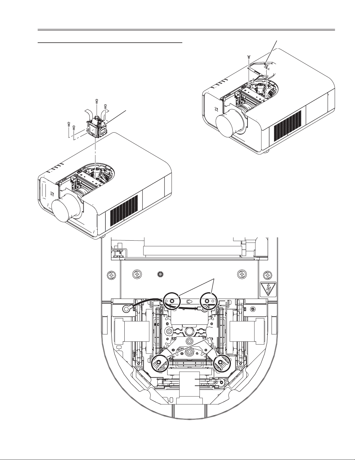
2-1 LCD panel/Prism ass'y removal
Prism shield cover
1 Remove 2 screws A (M3x6) and take the prism shield
cover off.
2 Remove 4 screws B (M2.5 x6) and take the LCD panel/
prism assembly upward off.
B
B
LCD panel/prism
B
B
assembly
A
A
B
B
-29-
Page 30
Optical Parts Disassembly
2-2 Polarized glasses-out removal
1 Remove 1 screw C (M2.5x6) on each stopper and take
the polarized glasses upward off.
C
Pre-Polarized glass (B)
Polarized glass-out (B)
(Blue)
C
(Green)
Pre-Polarized glass (G)
Polarized glass-out (G)
C
Pre-Polarized glass (R)
Polarized glass-out (R)
* Mount the glasses as the film
attached side comes to the LCD
panel side.
(Red)
Note; Do not replace the LCD panel separately otherwise it cannot obtain
proper picture. Do not touch the prism, the LCD panel and electrode
of flexible cable.
IMPORTANT NOTICE on LCD Panel/Prism Ass'y Replacement
LCD panels used for this model cannot be replaced separately. Do not disassemble the LCD Panel/Prism Ass’y.
These LCD panels are installed with precision at the factory. When replacing the LCD panel, should be replaced
whole of the LCD panels and prism ass’y at once.
When replacing LCD Panel/Prism ass’y, take the optical and electrical adjustments following to the chapter "Adjustment".
-30-
Page 31

Optical Parts Disassembly
LCD Panel Type Check
There are 2 types combination of the LCD panel/prism assembly and the optical unit, named Type-R and Type-L.
Since both have no compatibility, each type should be combined with the same type, and the specific parts should
be used. If not, the poor optical characteristics may degrade the quality of a projected image.
Confirm the "R" label or "L" label on top of the LCD panel/ prism assembly and the optical unit.
NOTE:
LCD panel/prism assembly should be used with the same type of the optical unit.
Confirm that both marking "R" is matched.
R
R
LCD Panel/Prism Ass'y Type-R
Confirm that both marking "L" is matched.
L
L
LCD Panel/Prism Ass'y Type-L
-31-
Page 32

Optical Parts Disassembly
Note on LCD Panel/Prism Ass’y Mounting
After replacing or installing the LCD Panel/Prism ass’y,
please make sure to obtain the best focus in both TELE and
WIDE zoom. If the focus adjustment is required, please adjust the positioning of LCD Panel/Prism Ass’y following to
the procedure below.
Focus adjustment:
1 Loosen 4 screws A on the LCD Panel/Prism ass’y with 2.0
mm hex driver.
2 Turn the projector on and project the image with WIDE
zoom, and adjust the FOCUS control to obtain the best
focus.
3 Turn the ZOOM control to the TELE position.
4 Insert a flat screw driver into the slot B and move the LCD
Panel/Prism Ass’y backward or forward by turning the
screwdriver left or right to obtain the proper focus. Confirm
the focus at TELE and WIDE zoom.
5 Tighten 4 screws A to fix the LCD Panel/Prism ass’y.
A
B
A
-32-
Page 33

Optical Parts Disassembly
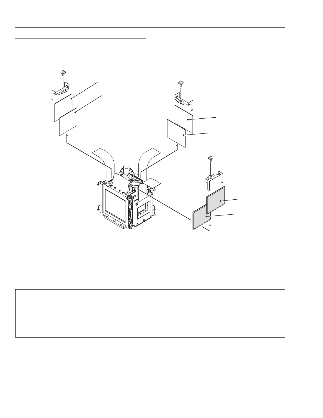
3 Polarized glass/Optical filter ass'y removal
1 Remove 1 screw A (M2.5x6) on each stopper and take the
polarized glasses upward off.
Glass holder
Stopper
marker
film
Polarized glass
A
A
Polarized glass/
Optical filter ass'y
Optical filter (HCP)
Red
Glass holder
Blue
Green
-33-
A
Page 34

Optical Parts Disassembly
TYPE-L
TYPE-R
3-1 Polarized glass/Optical filter mounting
There are 2 types combination of the LCD panel/prism assembly named Type-R and Type-L. Mount the polarized
glasses and optical filters according to the type of the LCD panel assembly as shown in the figure below
2 slits
Marker
Marker
(behind)
Polarized glass-in (B)
Optical filter-HCP (B)
* Polarized glasses should be
mounted as the film attached side
comes to the LCD panel side.
2 slits
Marker
Marker
Polarized glass-in (G)
Optical filter-HCP (G)
Marker
Optical filter-HCP (R)
Polarized glass-in (R)
2 slits
(behind)
2 slits
Polarized glass-in (B)
Optical filter-HCP (B)
* Polarized glasses should be
mounted as the film attached side
comes to the LCD panel side.
2 slits
(behind)
Polarized glass-in (G)
Optical filter-HCP (G)
Marker
Optical filter-HCP (R)
Polarized glass-in (R)
2 slits
-34-
Page 35

Optical Parts Disassembly
4 Optical base top removal
Before taking this procedure, remove cabinet top, main
board following to the chapter "Mechanical disassembly".
1 Remove 1 screw A (T3x8) on the thermostat, 1 screw B
(T3x8) on the ballast trigger and 4 screws C (T3x8).
2 Unhook 4 hooks D on the optical base top and take the
optical base top upward off.
Ballast trigger
D
B C
A
C
C
C
D
Thermostat
-35-
Page 36

Optical Parts Disassembly
238
241
240
238
490490
489489
241
240
4-1 Optical parts locations in the Optical Unit
No. Parts Name No. Parts Name
1 LENS,INTEGRATOR(IN) * 9 MIRROR(R)
2 LENS,INTEGRATOR(OUT) * 10 LENS,RELAY(IN)
3 ASSY,PRISM(PBS) 11 LENS,RELAY(OUT) *
4 LENS,CONDENSER(IN) 12 LENS,CONDENSER(R)
5 MIRROR(W-COLD) 13 MIRROR(B)
6 LENS,CONDERSOR(OUT) * 14 POLARIZED GLASS(IN/GB)
7 DICHROIC MIRROR (B) 15 LENS,CONDENSER(G)
8 DICHROIC MIRROR (G) 16 LENS,CONDENSER(B)
12
14
11
10
9
8
16
13
15
7
9
6
2
3
4
1
5
Shield Plate
Note:
The parts indicated with (*) are fixed with the adhesive onto the optical base bottom,
so these parts are not the replaceable parts.
-36-
Page 37

Optical Parts Disassembly
238
241
240
238
490490
489489
241
240
4-2 Optical parts directions in the Optical Unit
When mounting or assembling the optical parts in the optical unit, the parts must be
mounted in the specified location and direction as shown in the figure below.
Mount as the marker
comes this side up.
Mount as the marker
comes this side up.
Mount as the part no.
is facing this side
Mount as the part no.
is facing this side
-37-
Page 38

Adjustments
Adjustments after Parts Replacement
LCD/
Prism Ass’y
Adjustment
Optical
●: Adjustment necessary ❍: Check necessary
Disassembly / Replaced Parts
Polarized
Glass
Optical Filter
Power Board Main Board Fan s
Contrast adjustment
Panel type check and setting
Fan control adjustment
PC-auto calibration
Electrical Adjustments
Video-auto calibration -1
Video-auto calibration -2
Common center adjustment
Gamma shift adjustment
White balance adjustment [PC]
Gamma correction adjustment [PC]
White balance adjustment [AV]
Gamma correction adjustment [AV]
White uniformity adjustment
Wind sensor calibration
● ● ●
❍ ●
● ● ●
●
●
●
● ●
● ●
● ●
● ●
● ●
● ●
❍ ❍ ❍ ❍
● ● ●
Note on the main board replacement
When replacing the main board, take read/write procedure of the gamma adjustment data and color shading correction data.
The “gamma adjustment data” and “color shading correction data” of each panel have been adjusted precisely at
the factory to match the characteristics of each panel.
When you replace the main board, you need to read out the "gamma adjustment data" and "color shading correction data" stored in the memory IC on the previous main board and write down them into the memory IC on the
new main board. By this way, the projector is enabled to reproduce the picture which has the properly adjusted
gamma characteristic and color shading correction.
Use "Projector Service Tool" software for Read/Write of the gamma adjustment data and color shading correction
data. This tool also enable to correct the color shading and gamma characteristics.
PROJECTOR SERVICE TOOL v. 4.10
SERVICE PARTS NO.: 610 337 8787
-38-
Page 39

Optical Adjustments
Contrast adjustment
[Before Adjustment]
- Input a 100% of black raster signal.
1. Loosen a screw A on the polarized glass stopper which you intend to adjust.
2. Turn the lever B of optical filter as shown in figure to obtain the darkest brightness on the screen.
3. Turn the lever C of polarized filter as shown in figure to obtain the darkest brightness on the screen.
4. Tighten the screw A to fix the polarized glass stopper.
Repeat steps 1 to 4 for remaining R, G or B contrast adjustment.
Lever C
(Polarized filter)
Lever B
(Optical filer)
-39-
A
Page 40

Service Mode
Input Video
Group No. Data
0 0 32
Ver. R 1.00
Electrical Adjustments
Service Adjustment Menu Operation
To enter the service mode
To enter the “Service Mode”, press and hold the MENU and SELECT button for more than 3 seconds. The service
menu appears on the screen as follows.
To adjust service data
Select the adjustment group no. by pressing the MENU button (increase) or SELECT button (decrease), and
select the adjustment item no. by pressing the pointer e or d button, and change the data value by pressing the
7 or 8 button. Refer to the “Service Adjustment Data Table” for further description of adjustment group no., item
no. and data value.
To exit the service mode
To exit the service mode, press the ON/STAND-BY button.
Group No.
Item No.
Data value
Memory IC (IC301, IC802) Replacement
Memory ICs on the main board stores the data for the
service adjustments, and should not be replaced except for the case of defective device.
If replaced, the re-adjustments are required following to
the “Electrical Adjustments”.
The data of lamp replacement counter is stored in the
Memory IC.
Please note that the lamp replace counter will be reset
when the memory IC is replaced.
(Lamp replace counter cannot be set to the previous
value.)
●Caution to memory ICs replacement
When memory ICs are replaced with new one, the CPU
writes down the default data of the service adjustments
to the replaced ICs as the mentioned on the service adjustment table. As these data are not the same data as
factory shipped data, it should be required to perform
the re-adjustments following to the “Electrical Adjustments”.
Please note that in this case the lamp replace counter
will be reset.
●Caution of Main Board replacement (in the case
memory ICs are not defective)
When the main board is replaced, memory ICs should
be replaced with the one on previous main board. After
replacement, it should be required to perform the re-adjustments following to the “Electrical Adjustments”.
In this case, the value of lamp replace counter can be
kept as before.
-40-
Page 41

Electrical Adjustment
White 100%
Black 100%
Circuit Adjustments
CAUTION: The each circuit has been made by the fine adjustment at factory. Do not attempt to adjust the following
adjustments except requiring the readjustments in servicing otherwise it may cause loss of performance
and product safety.
[Adjustment Condition]
16 steps gray scale pattern
● Input signal
Video signal ......................
1.0Vp-p/75W terminated, 16 steps gray scale
(Composite video signal)
Computer signal ................. 0.7Vp-p/75W terminated, 16 steps gray scale
pattern
Component Video signal .... 0.7Vp-p/75W terminated, 16 steps gray scale
(Component video signal with 480p, 575p,
720p or 1080i format)
● Picture control mode ......
“STANDARD” mode unless otherwise noted.
Note:
* Please refer to “Service Adjustment Menu Operation” for entering the service mode and adjusting the service
data.
z Panel Type Check and Setting
* Before setting, you need to check which type of LCD pan-
el is placed on the projector according to the item "LCD
Panel/Prism Ass'y removal" in the chapter "Optical Parts
Disassembly".
1. Enter the service mode.
2. Panel Type Check
Select group no. “290”, item no. “0”. Check the data
value as follows;
Data value: 0 For L-Type of LCD Panel
Data value: 20 For R-Type of LCD panel
3. Panel Type Setting
Select group no. “290”, item no. “1” and change data
value from 10 to 0 or 20 depending on your LCD Panel
type. When the data value reaches 0 or 20, it returns
to 10 quickly. The gamma-characteristics is reset ac-
cording to your selection.
Note:
Be careful to take this adjustment. The value of gamma
adjustment data will be reset and cannot be restored
if you change the mode of LCD panel type.
x Fan Voltages adjustment
1. Enter the service mode.
2. Connect a digital voltmeter to test point
chassis ground (-). (7 test points are provided for this
adjustment, perform all the voltage adjustments in
the table below.)
3. Select group no. “140”. Select item no. B and
change data value to adjust the voltage to be C - 0.1V
+ 0V, and select item no. D and change data value
to adjust the voltage to be E ±0.1V.
4. Repeat step 2 to 3 for the remaining test points in
the table below.
Test Point A Item B Voltage C Item D Voltage E
TPFN5 0 13.8 1 5.0
TPFN3 2 13.8 3 5.0
TPFN4 2 13.8 3 5.0
TPFN2
TPFN1 6 13.8 7 5.0
TPFN7 8 13.8 9 5.0
4 13.8 5 5.0
A (+) and
TPFN6 10 13.8 11 5.0
-41-
Page 42

Electrical Adjustment
c PC-Auto Calibration
1. Enter the service mode.
2. Receive the 16-step grey scale computer signal with
Input 1 [PC analog] mode.
3. To start the auto-calibration for PC adjustment, select
group no. “680”, item no. “0” and then change data
value from “0” to “1”. After the auto-calibration completed, "OK" will appear on the screen.
v Video-Auto Calibration -1
1. Enter the service mode.
2. Receive the 16-step grey scale 480i-component vid-
eo signal with Input 2 [Y,Pb/Cb,Pr/Cr] mode.
3. To start the auto-calibration for Video adjustment, se-
lect group no. “680”, item no. “0” and then change
data value from “0” to “1”. After the auto-calibration
completed, "OK" will appear on the screen.
b Video-Auto Calibration -2
1. Enter the service mode.
2. Receive the 16-step grey scale composite video sig-
nal with Input 3 [Video] mode.
3. To start the auto-calibration for composite video ad-
justment, select group no. “680”, item no. “0” and then
change data value from “0” to “1”. After the auto-calibration completed, "OK" will appear on the screen.
m Gamma Shift adjustment
1. Receive the 100%-whole-white computer signal with
Input 1 [PC analog] mode.
2. Enter the service mode.
3. Measure luminance on the screen with the luminance
meter. It is A for the reading of luminance meter.
4. Change the signal source to the 50%whole-white
computer signal with Input 1 [PC analog] mode.
5. Select group no. “920”, item no. “6” and change the
Data value to make the reading of luminance meter to
be A x 22% .
, White Balance adjustment [PC]
This adjustment is carried out in the both of image mode
"Standard" and "Real".
1. Receive the 50%-whole-white computer signal with
Input 1 [PC analog] mode.
2. Set image mode to "Standard" or "Real" you intend to
adjust.
3. Enter the service mode, select group no. “920” item
no. “5” (Red) or “7” (Blue), and change Data values
respectively to make a proper white balance.
Conform that proper white balance is obtained in the
both of image mode "Standard" and "Real".
n Common Center adjustment
1. Receive the 50%-Whole Gray composite video sig-
nal with Input 3 [Video] mode.
2. Enter the service mode.
3. Select group no. “100”, item no. “92” and change
data value to “2” to reduce the panel frequency.
4. Project only green light component to the screen.
5. Select group no. “200”, item no. “9” and change
data value to obtain the minimum flicker on the
screen.
6. Project only blue light component to the screen.
7. Select item no. “10” and change data value to obtain
the minimum flicker on the screen.
8. Project only red light component to the screen.
9. Select item no. “11 and change data value to obtain
the minimum flicker on the screen.
10. Select group no. “100”, item no. “92” and change
data value to “0” to reset the panel frequency.
. Gamma Correction adjustment [PC]
This adjustment is carried out in the both of image mode
"Standard" and "Real".
1. Receive the 16-step grey scale computer signal with
Input 1 [PC analog] mode.
2. Set image mode to "Standard" or "Real" you intend to
adjust.
3. Enter the service mode, select group no. “920”, item
no. “6” and change the Data value to make a proper
16 steps gradation.
Conform that proper 16 steps gradation is obtained in
the both of image mode "Standard" and "Real".
-42-
Page 43

Electrical Adjustment
⁄0 White Balance adjustment [AV]
This adjustment is carried out in the both of image mode
"Standard" and "Cinema".
1. Receive the 50%-whole-white composite video signal
with Input 3 [Video] mode.
2. Set image mode to "Standard" or "Cinema" you intend to adjust.
3. Enter the service mode, select group no. “920” item
no. “5” (Red) or “7” (Blue), and change Data values
respectively to make a proper white balance.
Conform that proper white balance is obtained in the
both of image mode "Standard" and "Real".
⁄1 Gamma Correction adjustment [AV]
This adjustment is carried out in the both of image mode
"Standard" and "Cinema".
1. Receive the 16-step grey scale composite video signal with Input 3 [Video] mode.
2. Set image mode to "Standard" or "Cinema" you intend to adjust.
3. Enter the service mode, select group no. “920”, item
no. “6” and change the Data value to make a proper
16 steps gradation.
⁄3 Wind Sensor Calibration
1. Enter the service mode, select group no. “170” and
item no. “0” .
2. To start the calibration, change data value from “0”
to “1”. During the calibration, the word "Please wait..."
appears on the screen. After the calibration completed correctly, "OK" will appear on the screen.
IMPORTANT
Before taking this adjustment, you need to replace the
filter cartridge with new one or scrolled up to new filter.
Conform that proper 16 steps gradation is obtained in
the both of image mode "Standard" and "Cinema".
⁄2
White Uniformity Adjustment
If you find the color shading on the screen, please adjust
the white uniformity by using the proper computer and
“Projector Service Toll” software supplied separately.
-43-
Page 44

Electrical Adjustment
K47A
K47B
K1401
IC9201
IC4401
IC4801
K8B
K8C
K8D
K8E
K8J
K8H
K8K
K8L
K8M
K8N
K8X
IC401
IC801
K78BK78H
K78C
K78D
K78E
K78F
K78G
IC1201
IC4701
K25B
K25G
IC101
K25R
IC301
K78A
TPFN2
TPFN7
TP501
TP503TPFN6
TPFN5
TPFN4
TPFN3
TPFN1
TP561
TP563
TP531
TP533
Test Points and Locations
MAIN BOARD
-44-
Page 45

Electrical Adjustment
Service Adjustment Data Table
These initial values are the reference data written from the
CPU ROM to memory IC when replaced new memory IC. The
adjustment items indicated with “✻” are required to readjust following to the “Electrical adjustments”. Other items should be
used with the initial data value.
Grp Item Item Name Function Range Initial
0 Temperatu re Monitor [ Read only ]
0 LM76( Temp) A Monitor Temp. Sensor A ( Room: IC1692) - -
1 LM76( Temp) B Monitor Temp. Sensor B ( Lamp: IC1816) - -
2 LM76( Temp) C Monitor Temp. Sensor C (Pan el:IC1814) - -
1 Pressu re Sensor Mo nitor [R ead only]
0 MPXHZ6115A(Pressure) Monit or Pressure Se nsor - -
1 MPXHZ6115A(Pressure) Monit or Pressure Se nsor [mm Hg] - -
2 MPXHZ6115A(Pressure) Monit or Pressure Se nsor [hpa] - -
3 Angle Sensor Mon itor [Rea d only]
0 MAS1390 (Acc eleratio n) A Monito r Angle Se nsor A -
1 MAS1390 (Acc eleratio n) B Monito r Angle Se nsor B -
4 Wind Se nsor Moni tor [Read o nly]
0 Flow Senso r Monitor Wind Sens or -
5 Fan Voltag e Monitor [ Read only ]
0 FAN A Monitor ( Exhaust : Large ) Fan voltage (x0.01V) [A01] - -
1 FAN B Monitor ( Exhaust : Small ) Fan vol tage (x0.01V) [ A02] - -
2 FAN C Monitor ( PBS) Fan voltag e (x0.01V) [A03 ] - -
3 FAN D Monitor ( Power) Fan voltage (x0.01V) [A0 4] - -
4 FAN E Monitor ( Panel Cool ling) Fan voltag e (x0.01V) [A05 ] - -
5 FAN F Monitor ( Panel Cool ling) Fan vol tage (x0.01V) [A06] - -
-
10 RS232C Se tting
0 Baudrate RS232C Bau d Rate (0 :19200 / 1:9600) 0 / 1 0
1
11 PJ-Net Set ting
0 Reset Dis able PJ-Net Rese t (0: Enable / 1: Disable) 0 / 1 0
20 Logo Proh ibition
0 Logo Prohi bition 0: Menu, 1: Pr ohibiti on 0 / 1 0
30 Color Sh ading /Gamm a Correct ion
0 Color Sha ding Corre ction On /Off 0: Off, 1:O n *Not memor ized 0 / 1 1
1 Gamma Cor rection O n/Off 0: Of f, 1:On *Not memorized 0 / 1 1
40 Dimmer
0
1 Dimmer Leve l 0:Min.W ~ 15: Max.W *Mem orized 0 ~ 15 11
2 DIMMER CTR L LEVEL1 Luminance Level 1 Data f or Dimmer: L ess than val ue 0 ~ 255 7
3 DIMMER CTR L LEVEL2 Luminance Level 2 Data f or Dimmer: L ess than val ue 0 ~ 255 14
4 DIMMER CTR L LEVEL3 Luminance Level 3 Data f or Dimmer: L ess than val ue 0 ~ 255 21
5 DIMMER CTR L LEVEL4 Luminance Level 4 Data f or Dimmer: L ess than val ue 0 ~ 255 28
6 DIMMER CTR L LEVEL5 Luminance Level 5 Data f or Dimmer: L ess than val ue 0 ~ 255 35
7 DIMMER CTR L LEVEL6 Luminance Level 6 Data f or Dimmer: L ess than val ue 0 ~ 255 42
8 DIMMER CTR L LEVEL7 Luminance Level 7 Data f or Dimmer: L ess than val ue 0 ~ 255 49
9 DIMMER CTR L LEVEL8 Luminance Level 8 Data f or Dimmer: L ess than val ue 0 ~ 255 56
10 DIMMER CTRL LEVEL 9 Lumi nance Level 9 D ata for Dimmer: Less tha n value 0 ~ 255 63
11 DIMMER CTRL LEVEL10 Lumina nce Level 10 Data fo r Dimmer: Le ss than valu e 0 ~ 255 70
12 DIMMER CTRL LEVEL11 Lumina nce Level 11 Data for Dim mer: Less t han value 0 ~ 255 77
13 DIMMER CTRL LEVEL12 Lumina nce Level 12 Data for D immer: Le ss than value 0 ~ 255 84
14 DIMMER CTRL LEVEL13 Lumina nce Level 13 Data for D immer: Le ss than value 0 ~ 255 91
15 DIMMER CTRL LEVEL14 Lumina nce Level 14 Data for D immer: Les s than value 0 ~ 255 98
16 DIMMER CTRL LEVEL15 Lumina nce Level 15 Data for D immer: Le ss than value 0 ~ 255 105
17 DIMMER AVE POINT Dimmer Avar age Points 1~16 4
50 Auto Pict ure Contro l
0 Auto Pictu re Control Fo rced OFF 0: Me nu 1: Forced O ff *Memorized 0 / 1 Ini tial =1, Ship= 0
70 COOLIN G
-45-
Page 46

Electrical Adjustment
Grp Item Item Name Function Range Initial
0 COOLING _TIME Coolin g time at Power O ff 10 ~ 120 90
1 Not used Not us ed -1
80 Projec tor used tim e Reset
0 PJ Time Reset Time is re set when the va lue is set to 10. 0 ~ 10 0
90 Operat ion histor y
0 OPERATION_ HISTORY_1 Last Operation hi story 0 ~ 32767 0
~ : : : :
49 OPERATION_HISTO RY_50 50t h Operati on histor y 0 ~ 32767 0
50 OPERATION_HISTO RY Reset History is r eset when th e value is set to 10. 0 ~ 10 0
91 Error Log * Refer to Error Log tab le
0 Warning _Log_1 L ast Error Lo g 0 ~ 32767 0
~ : : : :
49 Warning_Lo g_50 5 0th Error Log 0 ~ 32 767 0
50 Warning_Lo g Reset Log is reset whe n the value is s et to 10. 0 ~ 10 0
112 Lamp Co nfig
0 Lamp Con fig Change L amp Life Sel ect 1000 ~ 80 00 2500
113 Lamp Res et Counter [ Read only ]
0 Lamp Rese t times Lamp rese t times 0 ~ 127 0
115 Lamp Go O ut
0 Lamp Go Ou t 0 :Disa ble / 1:Ena ble - 0
116 Lamp Rep lace Dips play
0 Lamp tim e display 0:D isable / 1: Enable 0/1 1
117 Lamp Life Test
0 Lamp life test enable 0:Disa ble 1:Ena ble for Safet y check - 0
1 Lmap On tim e(for l ife test) Minutes for Safety ch eck - 1
2 Lamp Of f time( for life test) M inutes for Safety chec k - 3
3 Lamp tota l time( for life test) Hours for Safety che ck - 0
120 RC KEY Dis able
0
1 RC KEY Front /Rear Disab le 0: Enable / 1: Front RC Disa ble / 2:R ear RC Disab le / 3:RC KEY All Disable 0 / 1 / 2 / 3 0
2
130 75 ohm terminated
0 TERM_1 In put1(D_ SUB)75 ohm terminated ON/ OFF (0 :OFF 1: ON) 0 / 1 0
1 TERM_ 2 Input2( BNC)75 ohm term inated ON /OFF (0: OFF 1:ON ) 0 / 1 0
140 Fan Adjust ment
0 Fan A Max (DAC ) Fan DAC Output adjust ment 0 ~ 255 2 24
1 Fan A Min (DAC ) * Lamp Mode : Forced Eco 0 ~ 255 3 8
2 Fan B Max (DAC ) 0 ~ 255 22 5
3 Fan B Min (DAC ) Volmin =5V 0 ~ 255 3 6
4 Fan C Max (DAC ) Volm ax=13.8V 0 ~ 255 22 9
5 Fan C Min (DAC ) ( DACmax - DACmin ) / (Volmax - Volmin) * (Volnow - Volmin) + DACmin 0 ~ 25 5 35
6 Fan D Max (DAC ) 0 ~ 255 227
7 Fan D Min (DAC ) 0 ~ 255 38
8 Fan E Max (DAC ) 0 ~ 255 22 2
9 Fan E Min (DAC ) 0 ~ 255 3 6
10 Fan F Max (DAC) 0 ~ 255 22 2
11 Fan F Min (DAC) 0 ~ 255 3 8
141 Fan Optio n
142 Fan Temp Error Set ting [Re ad only} Read only
0 Temp A Warning Temp. A (Room ) to judge fo r abnormal t emp (x0.1°C) 0 ~ 1000 470
1 Temp B Warning Temp. A (Lamp) to judge for abnorma l temp (x0.1°C) 0 ~ 1000 750
2 Temp C Warning Temp. A (Panel) to judge for abn ormal temp ( x0.1°C) 30 0 ~ 1000 6 50
3 Temp B-A Warning Temp. B-A ( Filter Clogge d) to judge f or abnorma l temp (x0.1°C) 0 ~ 1000 500
4 Temp C-A Warning Temp. C-A (F ilter Clog ged) to judge for abno rmal temp (x 0.1°C) 0 ~ 1000 310
-46-
Page 47

Electrical Adjustment
Grp Item Item Name Function Range Initial
143 Fan Manual C ontrol
0 Fan Fix SW
1 Fan Manual SW FanManual Control SW 0 :Auto / 1:Manual * Not memorize d 0 / 1 0
2 Fan A Manual O ut
3 Fan B Manual O ut 0 ~ 2000 1350
4 Fan C Manual O ut 0 ~ 2000 1350
5 Fan D Manual O ut 0 ~ 2000 1350
6 Fan E Manual O ut 0 ~ 2000 1350
7 Fan F Manual O ut 0 ~ 200 0 1350
144 Fan Table Setting
0 Fan Control Max Temp Fan control rang e of Temp Sensor A (x0 .01V) 300 ~ 100 0 380
1 Fan Control Min Temp 0 ~ 1000 310
2 Fan A Normal M ax (Volt) Fan contr ol range at L amp Normal ( x0.01V) 0 ~ 2000 1350
3 Fan A Normal M in (Volt) * It does not c hange wit h real time 0 ~ 2000 900
4 Fan B Normal M ax (Volt) 0 ~ 2000 1350
5 Fan B Normal M in (Volt) 0 ~ 2000 700
6 Fan C Normal M ax (Volt) 0 ~ 2000 1380
7 Fan C Normal M in (Volt) 0 ~ 2000 1380
8 Fan D Normal M ax (Volt) 0 ~ 2000 1350
9 Fan D Normal M in (Volt) 0 ~ 2000 1200
10 Fan E Normal Max ( Volt) 0 ~ 2000 1350
11 Fan E Normal Min (Vol t) 0 ~ 2000 700
12 Fan F Normal Max ( Volt) 0 ~ 2000 1350
13 Fan F Normal Min (Vol t) 0 ~ 2000 700
14 Fan A Eco Max (Volt) Fan control range at Eco N ormal (x0 .01V) 0 ~ 2000 1350
15 Fan A Eco Min (Volt) * It does n ot change in real time 0 ~ 200 0 500
16 Fan B Eco Max (Volt) 0 ~ 2000 1350
17 Fan B Eco Min (Volt) 0 ~ 2000 500
18 Fan C Eco Max (Volt) 0 ~ 2000 70 0
19 Fan C Eco Min (Volt) 0 ~ 2000 70 0
20 Fan D Eco Max (Volt) 0 ~ 2000 1350
21 Fan D Eco Min (Volt) 0 ~ 2000 1100
22 Fan E Eco Max (Volt) 0 ~ 2000 1350
23 Fan E Eco Min (Volt) 0 ~ 2000 500
24 Fan F Eco Max (Volt) 0 ~ 200 0 1350
25 Fan F Eco Min (Volt) 0 ~ 200 0 500
0:n ormal / 1: Normal Mi n / 2:Normal Max / 3 :Eco Mi n / 4 :Eco Ma x
* Not memorized , Abnor mal temp =100°C
Fan Voltage at M anual Mod e * Not memorized (x0.01V)
* Effect ive only Fan Manual SW is 1
0 ~ 4 0
0 ~ 2000 1350
145 Fan Temp. Offse t Setting
0 Temp A Warning Of fset (Temp) Temp. warning of fset value a t Power On (x0.1℃ ) 0 ~ 200 170
1 Temp B Warning Of fset (Temp) 0 ~ 200 170
2 Temp C Warning Of fset (Temp) 0 ~ 200 170
3 Temp B-A Warning O ffset (Temp) 0 ~ 200 170
4 Temp C-A Warning O ffset (Temp ) 0 ~ 200 170
5 Temp A Warning Of fset (Tim e) Temp. warning o ffset tim e at Power On (se c.) 0 ~ 30 0 180
146 Fan Star t Setting
0 Fan Start S tep (Volt /Sec ) Voltage deviation/1 sec at Fan start (Volt/ Sec) 0 ~ 200 0 20
1 Fan A Start Vol t Fa n start vol tage (x0.01V) 0 ~ 2000 700
2 Fan B Start Vol t 0 ~ 2000 700
3 Fan C Start Vol t 0 ~ 2000 70 0
4 Fan D Start Vol t 0 ~ 2000 70 0
5 Fan E Start Vol t 0 ~ 2000 700
6 Fan F Start Vol t 0 ~ 200 0 700
147 Fan Pressur e Setting
0 Press Sour ce Range Low Press se nsor contr ol range (mmHG) 0~1024 525
1 Press Sour ce Range Hi gh 0~1024 700
2 Press Fan Add Range High 0 ~ 2000 0
3 Press Fan Add Range Low 0 ~ 2000 650
148 Fan Ceilin g Setting
0 FAN A Ceiling O ffset Offset volt age at Ceili ng (x0.01V) 0 ~ 2000 0
1 FAN B Ceiling O ffset 0 ~ 2000 0
2 FAN C Ceiling O ffset 0 ~ 2000 0
3 FAN D Ceiling O ffset 0 ~ 2000 0
4 FAN E Ceiling O ffset 0 ~ 200 0 0
4 FAN F Ceiling O ffset 0 ~ 2 000 0
-47-
Page 48

Electrical Adjustment
Grp Item Item Name Function Range Initial
149 Fan Clogg ed Setting
0 Temp C-A Upward High Fan voltage add ition by Se nsor A - C temp Upw ard High 0 ~ 1000 3 00
1 Temp C-A Upward Lo w Fan voltage addit ion by Senso r A - C temp Upward L ow 0 ~ 1000 2 80
2 Temp C-A Downwar d High Fan voltage addition by Se nsor A - C temp Dow nward High 0 ~ 1000 150
3 Temp C-A Downwar d Low Fan voltage addit ion by Senso r A - C temp Downward Low 0 ~ 1000 110
150 Shipping Setting
0 Shipping Setting S hipping S et when the value is set to 10. 0 ~ 10 0
170 Wind Sen sor
0 Flow Senso r Calibrat ion
1 Flow Senso r Offset M in
2 Flow Senso r Offset M ax
3 Flow Senso r Calibrat ion Error Log
4 Clog Chec k Enable Clogged D etectio n (0: Di sable / 1: Enable) 0 ~ 1 Initial =0, Sh ip=1
171 Wind Sen sor
0 Ideal Flo w Data Air flow data th eory for c urrent fan vol tage (Re ad only) - -
1 Flow Dif ference Dat a Dif ferentia l value betw een actual a nd theor y (Read onl y - -
2 Clog Dete ct Flow Dif ference Dat a “Dif ferential value to judg e “Clogg ed”( Read only) - -
3 Warn Detect Flow Diffe rence Data
4 Press Add Data Additional value o f press sens or - -
5 Filter Scr oll Timer
175 Filter
0 Compuls ion Filter Taking Up
1 Take Up Bend
2 Take Up Times Filter scr oll remaining times ( Read only ) - 9
3 Take Up Time Reset
4 Scroll Counter Reset T ime S croll Cou nter reset ti mes (Read o nly) 0 ~ 25 5 0
Wind Sen sor Offset Auto-Ca libration
Calibra tion star ts when the val ue is set to 1. After cal ibration, OK is displaye d.
Wind Sen sor Mini Of fset value
* After ca libration, the value i s set automat ically.
(Of fset Range : 350 - 550 )
Wind Sen sor Max Of fset value
* After ca libration, the value i s set automat ically.
(Of fset Range : 550 - 800 )
Error Log fo r Auto-Ca libratio n
0: No Err or
10: Min no t stabilize d
11: Min out of offs et range
20: Ma x not stabi lized
21: Max out of offset ran ge
“Dif ferential value to judg e “Clogg ed warning" (Read onl y)
Judge w hen the rema ining scro ll times is 0.
Filter sc roll timer (hours)(Read o nly)
* Execut e at 2000 hou rs
Filter sc roll force dly
*Execu te when the val ue is set to 1
Remove flexu re of filter
*Execu te when the val ue is set to 1
Reset of sc roll up tim es
*Reset wh en the value is set to 10.
0 ~ 1 0
0 ~ 1023 0
0 ~ 1023 0
- -
- -
0 ~ 1 0
0 ~ 1 0
0 ~ 10 0
176 Filter Di spplay
0 Filter Icon Display Di splay 0: D isable / 1: Enable 0 /1 1
177 Filter Ti mer
0 Filter Tim er Reset Tim es Filter time reset times with us er menu 0 ~ 255 0
1 Force Power Off Time Forced Po wer Off Tim e (hours ) 0 ~ 1000 10
180 DDC Setting
0 HDCP EDID Dat a Settin g 0:DVI EDID Dat a / 1:HDCP EDID Da ta 0 / 1 1
190 Panel Life Test
0 Panel Life en able 0: Test M ode ON, Test Mod e OFF 0 / 1 1
200 CXA7007
0 G SIG Center 0 ~ 63 32
1 B SIG Center 0 ~ 6 3 32
2 R SIG Center 0 ~ 63 32
3 G Gain Cont rol 0 ~ 255 194
4 B Gain Cont rol 0 ~ 2 55 194
5 R Gain Cont rol 0 ~ 255 194
6 G Bright Co ntrol 0 ~ 255 0
7 B Bright Co ntrol 0 ~ 2 55 0
8 R Bright Co ntrol 0 ~ 255 0
9 G VCOM Contr ol 0 ~ 255 104
10 B VCOM Control 0 ~ 255 104
11 R VCOM Control 0 ~ 255 104
-48-
Page 49

Electrical Adjustment
Grp Item Item Name Function Range Initial
12 G SID Control A 0 ~ 25 5 16
13 B SID Control A 0 ~ 255 16
14 R SID Control A 0 ~ 255 16
15 G SID Control B 0 ~ 25 5 130
16 B SID Control B 0 ~ 255 130
17 R SID Control B 0 ~ 255 130
18 G FRINV 0 ~ 1 0
19 B FRINV 0 ~ 1 0
20 R FRINV 0 ~ 1 0
290 Panel
0 PANEL_LR
1 PANEL_CHG
300 Built-i n Device : CXD3815
0 Compon ent Y Level
1 Compon ent C Level
2 CVBS Y Level
3 CVBS C Level
4 Sub Hue CVBS/ S Input (NTSC )Tint Adj. 0 - 63 32
5 HS Slice Level H Sync Slice L evel 0 - 15 4
6 HS Slice O ffset
7 VS Slice Level V Sync Slice Level 0 - 15 6
8 VS Slice Of fset Offse t for V Sync Sli ce Level 0 - 15 6
9 Samplin g Phase A /D Cloc k Phase 0 - 63 0
10 Pre Shoot Level Sub-Sh arpness 0 - 15 8
11 Over Shoot Level Sub-Sharp ness 0 - 15 8
12 Y Filter
13 C Filter
14 NTSC/PAL Dete ct
Panel Type Disp lay (Read o nly)
0: Type-L / 2 0: Type-R
Gamma da ta will be res et when the val ue is set to 0 or 20.
20: Type- R, 0: Type-L
Component Scar t Input Gain A dj.
Group 01 : <YCbCr >1080i-6 0, 1080i-5 0, 1035i
<RGB >1080i- 60, 1080i-50, 103 5i
Group 02 : <YCbCr>720p- 60, 720p -60
<RGB >720p-60, 720p-50
Group 03 : <YCbCr>48 0p, 575p
<RGB >480p, 575p
Group 04 : <YCb Cr>48 0i, 575i
<RGB >480i, 575i
Group 05 < Scart> 480i, 575i
Component SCart I nput Gain Ad j.
Group 01 : <YCbCr >1080i-6 0, 1080i-5 0, 1035i
<RGB >1080i- 60, 1080i-50, 103 5i
Group 02 : <YCbCr>720p- 60, 720p -60
<RGB >720p-60, 720p-50
Group 03 : <YCbCr>48 0p, 575p
<RGB >480p, 575p
Group 04 : <YCb Cr>48 0i, 575i
<RGB >480i, 575i
Group 05 < Scart> 480i, 575i N ote: Link w ith Group 4
CVBS/ Yinput Gain Adj.
Composite / S-VIDEO
C Input Ga in Adj.
Composite / S-VIDEO
Offse t of H Sync Sli ce Level
Group 01 : <YCbCr >480 i, 575i
Group 02 : <YCbCr>48 0p, 575p
Group 03 : <YCbCr>720p
Group 04 : <YCb Cr>1080i
Group 05 : O thers
Y Input Filter band Set ting
Group 01 : Composite, S -Video
Group 02 : 4 80i, 575i, 480p, 575p
Group 03 : 720p-6 0, 720p-5 0, 1035i, 1080 i-60, 108 0i-50
C Input Filter Band Set ting
Group 01 : Composite, S -Video
Group 02 : 4 80i, 575i, 480p, 575p
Group 03 : 720p-6 0, 720p-5 0, 1035i, 1080 i-60, 108 0i-50
NTSC/ PAL Detection Thres hold Sett ing
0 : 64H /1V - PAL Ident Strong
1 : 96H /1V
2 : 128H/1V
3 : 160H/1V - PAL Ident Weak
* Change i s effecti ve at System -Au to Select ion
- 0
0 ~ 20 10
0 - 255
0 - 255
0 - 255 162 /163
0 - 255 124/127
0 - 15
0 - 7
0 - 7
0 - 3 2
118
118
118
118
134
110
110
127
134
150
5
5
4
3
5
5
5
6
5
5
6
302 Built-i n Deveice : FPGA(D EMO_MOD E) SH
0 FPGA_ DEMO_ON_ OFF De mo mode On /Off( 0:O ff,1:On) * Not m emorized 0 ~ 1 0
1 FPGA_ DEMO_MO DE De mo mode Swi tch (0 :Demo0,1:Demo1 ・・・ ) * Not mem orized 0 ~ 3 0
303 Built-i n Device : FPGA(C olor Maneg .) S H
0 YRange Bright ness (Y) R ange 0 ~ 32 8
1 HueRang e Hue Range 0 ~ 2 0 10
2 GainRange Gain Range 0 ~ 50 30
-49-
Page 50

Electrical Adjustment
Grp Item Item Name Function Range Initial
3 GM_M inSlope Gam ma Mini Slo pe (x0.01) 0 ~ 10 3
4 GM_M axSlope Gamma Max S lope (x0.1) 10 ~ 30 18
5 GM_Converge G amma Convarg e Point Numb ers (x0.1) 1 ~ 5 3
6 Not used Not us ed - -
7 Not used Not us ed - -
8 COLM_GET_KIND_Y_ud Point Nu mbers at Col or Acquire d 1 ~ 9 9
9 Not used Not us ed - -
10 Not used Not used - -
11 SameHue H ue Comp sam e angle rang e 1 ~ 10 3
12 Cut_UVNorm Hue Co mp UV Norm Mi ni Value 0 ~ 64 5
13 Cur_MinY H ue Comp Bri ghtness M ini Value 0 ~ 127 0
14 Cur_MaxY Hue Co mp Bright ness Max Valu e 128 ~ 255 2 55
15 CM_IsAcc ess For Deb ag 0 ~ 1 1
310 Built-i n Device : AD9882
0 GREEN_OFFSET 0 - 127 63
1 RED_OFFSET 0 - 127 63
2 BLUE_OFFS ET 0 - 127 63
3 GREEN_GAI N 0 - 255 78
4 RED_GAIN 0 - 255 78
5 BLUE_GAIN 0 - 255 78
6 BANDWIDTH Analog 0 - 1 1
7 Last Cali b Table [Off set]
8 Last Cali b Table [Gain ]
9 OFFSET_THRESH_ 0
10 OFFSET_THRESH_1
11 OFFSET_THRESH_2
12 OFFSET_THRESH_3
13 OFFSET_THRESH_4
14 OFFSET_THRESH_5
15 GAIN_THRESH_ 0
16 GAIN_THRESH_1
17 GAIN_THRESH_ 2
18 GAIN_THRESH_ 3
19 GAIN_THRESH_ 4
20 GAIN_THRESH_ 5
21 OFFSET R 0 Under OFFSET Thresh X - X Diffe rential Data 0 - 25 5 121
22 OFFSET R 0-1 0 - 255 123
23 OFFSET R 1-2 0 - 255 124
24 OFFSET R 2-3 0 - 255 128
25 OFFSET R 3-4 0 - 255 131
26 OFFSET R 4-5 0 - 255 131
27 OFFSET R 5 Over 0 - 255 128
28 OFFSET G 0 Under OFFSET Thresh X - X D ifferen tial Data 0 - 255 123
29 OFFSET G 0-1 0 - 255 124
30 OFFSET G 1-2 0 - 255 125
31 OFFSET G 2-3 0 - 255 128
32 OFFSET G 3-4 0 - 255 131
33 OFFSET G 4-5 0 - 255 130
34 OFFSET G 5 Over 0 - 255 128
35 OFFSET B 0 Under OFFSE T Thresh X - X Differenti al Data 0 - 255 126
36 OFFSET B 0-1 0 - 255 125
37 OFFSET B 1-2 0 - 255 126
38 OFFSET B 2-3 0 - 255 128
39 OFFSET B 3-4 0 - 255 132
40 OFFSET B 4-5 0 - 255 133
41 OFFSET B 5 Over 0 - 2 55 128
42 GAIN R 0 Under GAIN Thresh X - X Differe ntial Data 0 ~ 255 129
43 GAIN R 0-1 0 - 255 129
Frequency Range at Auto-Calibration *Re ad only
255 is def ault
0:OFFSET_Thresh 0 les s
1:OFFSET_Thresh 0 - 1
2:O FFSET_Thresh 1- 2
3:O FFSET_Thresh 1- 2
~~
6:O FFSET_Thresh 5 more
Frequency Range at Auto-Calibration *Re ad only
255 is def ault
0:OFFSET_Thresh 0 les s
1:OFFSET_Thresh 0 - 1
2:O FFSET_Thresh 1- 2
3:O FFSET_Thresh 1- 2
~~
6:O FFSET_Thresh 5 more
【MHz】
【MHz】
【MHz】
【MHz】
【MHz】
【MHz】
【MHz】
【MHz】
【MHz】
【MHz】
【MHz】
【MHz】
0 - 6 255
0 - 6 255
0 - 255 70
0 - 255 80
0 - 255 85
0 - 255 100
0 - 255 120
0 - 255 140
0 - 255 70
0 - 255 80
0 - 255 85
0 - 255 100
0 - 255 120
0 - 255 140
-50-
Page 51

Electrical Adjustment
Grp Item Item Name Function Range Initial
44 GAIN R 1-2 0 - 255 129
45 GAIN R 2-3 0 - 255 128
46 GAIN R 3-4 0 - 255 127
47 GAIN R 4-5 0 - 255 126
48 GAIN R 5 Over 0 - 255 128
49 GAIN G 0 Under GAIN Thresh X - X Di fferential Data 0 - 255 129
50 GAIN G 0-1 0 - 255 129
51 GAIN G 1-2 0 - 255 129
52 GAIN G 2-3 0 - 255 128
53 GAIN G 3-4 0 - 255 127
54 GAIN G 4-5 0 - 255 126
55 GAIN G 5 Over 0 - 2 55 128
56 GAIN B 0 Under GAIN Thresh X - X Dif ferential D ata 0 - 255 130
57 GAIN B 0-1 0 - 255 127
58 GAIN B 1-2 0 - 255 127
59 GAIN B 2-3 0 - 255 128
60 GAIN B 3-4 0 - 255 128
61 GAIN B 4-5 0 - 255 127
62 GAIN B 5 Over 0 - 255 128
311 Built-i n Device : M62393FP
0 R_CLA MP 0 - 255 0
1 G_CLA MP 0 - 255 0
2 B_CLAM P 0 - 255 0
400 Composite (NTSC) C omposite / S -Video
0 Total Dots * Rea d only 0 ~ 3000 858
1 Disp Dots 0 ~ 3 000 66 8
2 H Back Porch 0 ~ 3000 128
3 V Back Porch 0 ~ 30 00 47
4 Disp Line 0 ~ 1500 4 56
5 * Not used
6 * Not used
7 * Not used
8 VSBEG 0 ~ 15 2
401 Composite (PAL) Composi te / S-Video
0 Total Dots * Rea d only 0 ~ 3000 864
1 Disp Dots 0 ~ 3 000 65 6
2 H Back Porch 0 ~ 3000 147
3 V Back Porch 0 ~ 30 00 64
4 Disp Line 0 ~ 1500 534
5 * Not used
6 * Not used
7 * Not used
8 VSBEG 0 ~ 15 2
410 SCART(48 0i)
0 Total Dots * Rea d only 0 ~ 3000 858
1 Disp Dots 0 ~ 3 000 66 8
2 H Back Porch 0 ~ 3000 130
3 V Back Porch 0 ~ 30 00 47
4 Disp Line 0 ~ 1500 4 56
5 * Not used
6 * Not used
7 * Not used
8 VSBEG 0 ~ 15 2
411 SCART (575i )
0 Total Dots * Rea d only 0 ~ 3000 864
1 Disp Dots 0 ~ 3 000 65 6
2 H Back Porch 0 ~ 3000 146
3 V Back Porch 0 ~ 30 00 64
4 Disp Line 0 ~ 1500 534
5 * Not used
6 * Not used
7 * Not used
8 VSBEG 0 ~ 15 2
-51-
Page 52

Electrical Adjustment
Grp Item Item Name Function Range Initial
420 YCbCr (480 i)
0 Total Dots * Rea d only 0 ~ 3000 858
1 Disp Dots 0 ~ 3 000 66 8
2 H Back Porch 0 ~ 3000 130
3 V Back Porch 0 ~ 30 00 47
4 Disp Line 0 ~ 1500 4 56
5 * Not used
6 * Not used
7 * Not used
8 VSBEG 0 ~ 15 2
421 YCbCr (575i)
0 Total Dots * Rea d only 0 ~ 3000 864
1 Disp Dots 0 ~ 3 000 65 6
2 H Back Porch 0 ~ 3000 146
3 V Back Porch 0 ~ 30 00 64
4 Disp Line 0 ~ 1500 534
5 * Not used
6 * Not used
7 * Not used
8 VSBEG 0 ~ 15 2
422 YCbCr (480 P)
0 Total Dots * Rea d only 0 ~ 3000 858
1 Disp Dots 0 ~ 3 000 68 4
2 H Back Porch 0 ~ 3000 122
3 V Back Porch 0 ~ 30 00 46
4 Disp Line 0 ~ 1500 4 60
5 * Not used
6 * Not used
7 * Not used
8 VSBEG 0 ~ 15 2
423 YCbCr (575P )
0 Total Dots * Rea d only 0 ~ 3000 864
1 Disp Dots 0 ~ 3 000 69 2
2 H Back Porch 0 ~ 3000 128
3 V Back Porch 0 ~ 30 00 56
4 Disp Line 0 ~ 1500 5 50
5 * Not used
6 * Not used
7 * Not used
8 VSBEG 0 ~ 15 2
424 YCbCr (720P - 60)
0 Total Dots * Rea d only 0 ~ 3000 1650
1 Disp Dots 0 ~ 3 000 1250
2 H Back Porch 0 ~ 3000 306
3 V Back Porch 0 ~ 30 00 34
4 Disp Line 0 ~ 1500 70 0
5 * Not used
6 * Not used
7 * Not used
8 VSBEG 0 ~ 15 2
425 YCbCr (720P- 50 )
0 Total Dots * Rea d only 0 ~ 3000 1980
1 Disp Dots 0 ~ 3 000 1250
2 H Back Porch 0 ~ 3000 304
3 V Back Porch 0 ~ 30 00 34
4 Disp Line 0 ~ 1500 70 0
5 * Not used
6 * Not used
7 * Not used
8 VSBEG 0 ~ 15 2
426 YCbCr (1080i -60)
0 Total Dots * Rea d only 0 ~ 3000 220 0
1 Disp Dots 0 ~ 3 000 1872
2 H Back Porch 0 ~ 3000 248
-52-
Page 53

Electrical Adjustment
Grp Item Item Name Function Range Initial
3 V Back Porch 0 ~ 30 00 54
4 Disp Line 0 ~ 1500 1050
5 *** * Not used
6 *** * Not used
7 *** * Not used
8 VSBEG 0 ~ 15 2
427 YCbCr (1035i )
0 Total Dots * Rea d only 0 ~ 3000 220 0
1 Disp Dots 0 ~ 3 000 1872
2 H Back Porch 0 ~ 3000 248
3 V Back Porch 0 ~ 30 00 90
4 Disp Line 0 ~ 1500 1012
5 * Not used
6 * Not used
7 * Not used
8 VSBEG 0 ~ 15 2
428 YCbCr (1080i -50)
0 Total Dots * Rea d only 0 ~ 3000 264 0
1 Disp Dots 0 ~ 3 000 1872
2 H Back Porch 0 ~ 3000 248
3 V Back Porch 0 ~ 30 00 54
4 Disp Line 0 ~ 1500 1050
5 * Not used
6 * Not used
7 * Not used
8 VSBEG 0 ~ 15 2
430 RGB Vide o (480i )
0 Total Dots * Rea d only 0 ~ 3000 858
1 Disp Dots 0 ~ 3 000 66 8
2 H Back Porch 0 ~ 3000 126
3 V Back Porch 0 ~ 30 00 47
4 Disp Line 0 ~ 1500 4 56
5 * Not used
6 * Not used
7 * Not used
8 VSBEG 0 ~ 15 2
431 RGB Vide o (575i)
0 Total Dots * Rea d only 0 ~ 3000 864
1 Disp Dots 0 ~ 3 000 65 6
2 H Back Porch 0 ~ 3000 143
3 V Back Porch 0 ~ 30 00 64
4 Disp Line 0 ~ 1500 534
5 * Not used
6 * Not used
7 * Not used
8 VSBEG 0 ~ 15 2
432 RGB Vide o (480P)
0 Total Dots * Rea d only 0 ~ 3000 858
1 Disp Dots 0 ~ 3 000 68 6
2 H Back Porch 0 ~ 3000 115
3 V Back Porch 0 ~ 30 00 46
4 Disp Line 0 ~ 1500 4 60
5 * Not used
6 * Not used
7 * Not used
8 VSBEG 0 ~ 15 2
433 RGB Vide o (575P)
0 Total Dots * Rea d only 0 ~ 3000 864
1 Disp Dots 0 ~ 3 000 69 2
2 H Back Porch 0 ~ 3000 122
3 V Back Porch 0 ~ 30 00 56
4 Disp Line 0 ~ 1500 5 50
5 * Not used
6 * Not used
-53-
Page 54

Electrical Adjustment
Grp Item Item Name Function Range Initial
7 * Not used
8 VSBEG 0 ~ 15 2
434 RGB Vide o (720P-6 0 )
0 Total Dots * Rea d only 0 ~ 3000 1650
1 Disp Dots 0 ~ 3 000 1250
2 H Back Porch 0 ~ 3000 289
3 V Back Porch 0 ~ 30 00 34
4 Disp Line 0 ~ 1500 70 0
5 * Not used
6 * Not used
7 * Not used
8 VSBEG 0 ~ 15 2
435 RGB Vide o (720P-50 ) * Re ad only
0 Total Dots 0 ~ 3 000 1980
1 Disp Dots 0 ~ 3 000 1250
2 H Back Porch 0 ~ 3000 287
3 V Back Porch 0 ~ 30 00 34
4 Disp Line * Not used 0 ~ 1500 700
5 * Not used
6 * Not used
7 * Not used
8 VSBEG 0 ~ 15 2
436 RGB Vide o (1080i-60)
0 Total Dots * Rea d only 0 ~ 3000 220 0
1 Disp Dots 0 ~ 3 000 1872
2 H Back Porch 0 ~ 3000 231
3 V Back Porch 0 ~ 30 00 54
4 Disp Line 0 ~ 1500 1050
5 * Not used
6 * Not used
7 * Not used
8 VSBEG 0 ~ 15 2
437 RGB Vide o (1035i)
0 Total Dots * Rea d only 0 ~ 3000 220 0
1 Disp Dots 0 ~ 3 000 1872
2 H Back Porch 0 ~ 3000 231
3 V Back Porch 0 ~ 30 00 90
4 Disp Line 0 ~ 1500 1012
5 * Not used
6 * Not used
7 * Not used
8 VSBEG 0 ~ 15 2
438 RGB Vide o (1080i-5 0)
0 Total Dots * Rea d only 0 ~ 3000 264 0
1 Disp Dots 0 ~ 3 000 1872
2 H Back Porch 0 ~ 3000 231
3 V Back Porch 0 ~ 30 00 54
4 Disp Line 0 ~ 1500 1050
5 * Not used
6 * Not used
7 * Not used
8 VSBEG 0 ~ 15 2
440 HDCP (48 0P)
0 * Not used
1 * Not used
2 * Not used
3 * Not used
4 * Not used
5 * Not used
6 * Not used
7 OverSca n Over Scan Rate( 0~25.5% : 0.1% Step) 0 ~ 25 5 0
8 VSBEG 0 ~ 15 2
441 HDCP (5 75P)
-54-
Page 55

Electrical Adjustment
Grp Item Item Name Function Range Initial
0 * Not used
1 * Not used
2 * Not used
3 * Not used
4 * Not used
5 * Not used
6 * Not used
7 OverSca n Over Scan Rate( 0~25.5% : 0.1% Step) 0 ~ 25 5 0
8 VSBEG 0 ~ 15 2
442 HDCP (720 P-60 )
0 * Not used
1 * Not used
2 * Not used
3 * Not used
4 * Not used
5 * Not used
6 * Not used
7 OverSca n Over Scan Rate( 0~25.5% : 0.1% Step)
8 VSBEG 0 ~ 15 2
443 HDCP (720 P-50 )
0 * Not used
1 * Not used
2 * Not used
3 * Not used
4 * Not used
5 * Not used
6 * Not used
7 OverSca n Over Scan Rate( 0~25.5% : 0.1% Step) 0 ~ 25 5 0
8 VSBEG 0 ~ 15 2
444 HDCP (1080 i-60 )
0 * Not used
1 * Not used
2 * Not used
3 * Not used
4 * Not used
5 * Not used
6 * Not used
7 OverSca n Over Scan Rate( 0~25.5% : 0.1% Step) 0 ~ 25 5 0
8 VSBEG 0 ~ 15 2
445 HDCP (1035i )
0 * Not used
1 * Not used
2 * Not used
3 * Not used
4 * Not used
5 * Not used
6 * Not used
7 OverSca n Over Scan Rate( 0~25.5% : 0.1% Step) 0 ~ 25 5 0
8 VSBEG 0 ~ 15 2
446 HDCP (1080 i-50)
0 * Not used
1 * Not used
2 * Not used
3 * Not used
4 * Not used
5 * Not used
6 * Not used
7 OverSca n Over Scan Rate( 0~25.5% : 0.1% Step) 0 ~ 25 5 0
8 VSBEG 0 ~ 15 2
447
0 * Not used
1 * Not used
2 * Not used
3 * Not used
-55-
Page 56

Electrical Adjustment
Grp Item Item Name Function Range Initial
4 * Not used
5 * Not used
6 * Not used
7 OverSca n Over Scan Rate( 0~25.5% : 0.1% Step) 0 ~ 25 5 0
8 VSBEG 0 ~ 15 2
448 HDCP (1080 -25psf)
0 * Not used
1 * Not used
2 * Not used
3 * Not used
4 * Not used
5 * Not used
6 * Not used
7 OverSca n Over Scan Rate( 0~25.5% : 0.1% Step) 0 ~ 25 5 0
8 VSBEG 0 ~ 15 2
449 HDCP (1080 -24psf)
0 * Not used
1 * Not used
2 * Not used
3 * Not used
4 * Not used
5 * Not used
6 * Not used
7 OverSca n Over Scan Rate( 0~25.5% : 0.1% Step) 0 ~ 25 5 0
8 VSBEG 0 ~ 15 2
450 RGB-Vid eo (1080-3 0psf)
0 Total Dots * Rea d only 0 ~ 3000 220 0
1 Disp Dots 0 ~ 3 000 1874
2 H Back Porch 0 ~ 3000 230
3 V Back Porch 0 ~ 30 00 54
4 Disp Line 0 ~ 1500 1050
5 * Not used
6 * Not used
7 * Not used
8 VSBEG 0 ~ 15 2
451 RGB-Vid eo (1080-25 psf)
0 Total Dots * Rea d only 0 ~ 3000 264 0
1 Disp Dots 0 ~ 3 000 1874
2 H Back Porch 0 ~ 3000 230
3 V Back Porch 0 ~ 30 00 54
4 Disp Line 0 ~ 1500 1050
5 * Not used
6 * Not used
7 * Not used
8 VSBEG 0 ~ 15 2
452 RGB-Vid eo (1080-24ps f)
0 Total Dots * Rea d only 0 ~ 3000 2750
1 Disp Dots 0 ~ 3 000 1874
2 H Back Porch 0 ~ 3000 250
3 V Back Porch 0 ~ 30 00 56
4 Disp Line 0 ~ 1500 1050
5 * Not used
6 * Not used
7 * Not used
8 VSBEG 0 ~ 15 2
453 RGB-Vid eo (1080P-6 0)
0 Total Dots * Rea d only 0 ~ 3000 1565
1 Disp Dots 0 ~ 3 000 1332
2 H Back Porch 0 ~ 3000 174
3 V Back Porch 0 ~ 30 00 56
4 Disp Line 0 ~ 1500 1050
5 * Not used
6 * Not used
7 * Not used
-56-
Page 57

Electrical Adjustment
Grp Item Item Name Function Range Initial
8 VSBEG 0 ~ 15 2
454 RGB-Vid eo (1080P-50 )
0 Total Dots * Rea d only 0 ~ 3000 1878
1 Disp Dots 0 ~ 3 000 1332
2 H Back Porch 0 ~ 3000 174
3 V Back Porch 0 ~ 30 00 56
4 Disp Line 0 ~ 1500 1050
5 * Not used
6 * Not used
7 * Not used
8 VSBEG 0 ~ 15 2
455 RGB-Vid eo (1080P-4 8)
0 Total Dots * Rea d only 0 ~ 3000 1957
1 Disp Dots 0 ~ 3 000 1332
2 H Back Porch 0 ~ 3000 174
3 V Back Porch 0 ~ 30 00 56
4 Disp Line 0 ~ 1500 1050
5 * Not used
6 * Not used
7 * Not used
8 VSBEG 0 ~ 15 2
600 PW Optio n
0 FrameLoc k Option
1 AV Screen Forc e True Mode
2 Field Sen se Invert Ena ble I nvert FLDINV Setting 0 : D isable / 1 : Ena ble 0 - 1 0
3
4
6 Device Ref resh Disable 0 : Enable (Norm al) / 1: Disa ble *Not mem orized 0 - 1 0
12 V-Sync Bigin Value Setu p V-SYnc Start val ue 0 - 15 2
605 Spread S pectrum Reset af ter AC Off
0 Enable 0 = Spreading Off / 1 = Spreading On 0 - 1 1
1 Spreadi ng Ratio Default value: 100 0 - 300 50
2 Modulat or Frequenc y Default valu e: 300 200 - 500 8 0
620 Sub Brig htnes
0 Center Con trast
1 Center Bri ghtness 0 - 1023
2 Center Col or 0 - 1023
3 Center Tin t
4 Center Sha rpness
5 Center Whi teBalanc e-Red 0-1023
6 Center Whi teBalanc e-Gree n 0-1023
7 Center Whi teBalanc e-Blue 0-1023
8 Center Bla ckBalan ce-Red 0-1023
9 Center Bla ckBalan ce-Gre en 0 -1023
10 Center Black Balance -Blue 0-1023
0: PC si gnal FrameLock OFF
1: PC signa l and Vfreq 47Hz~Panel fr equency r ange FrameLo ckON
AV Signal Natural Wide - > True change
0 : Disabl e / 1 : Enable <True at Natu ral Wide >
Composite / S-Vide o / Compone nt / Digital / D-RGB-Vide o
/Anal ogRGB / RGB -Video / HDCP- PC /HDC P-AV /SCART/ PJ-Net
Value = (Value at Menu - C enter Value of Me nu) x Alpha / 10 + Center
Contra st [Max] 1023 [Mi n] 0
Bright ness [M ax] 1023 [ Min] 0
Color [ Max] 1023 [ Min] 0
Tint [ Max] 180 [ Min] 0
Sharpn ess [Ma x] 23 [M in] 0
WB-Re d [Max ] 1023 [Min ] 0
WB-Green [Ma x] 1023 [M in] 0
WB-B lue [Ma x] 1023 [Min] 0
BB-Re d [Max ] 1023 [Min ] 0
BB-G reen [Max] 1023 [M in] 0
BB-B lue [Ma x] 1023 [M in] 0”
0 - 1 1
0 - 1 0
0 - 1023
577/ 577/577/492 /492
/53 5/57 7/492 /492 /572/ 492
512/512/ 512/512/512
/50 8/512/ 512/512/ 520/ 512
512/512/ 512/512/512
/512/ 512/512/512/ 512/512
95/ 95/95 /95 /95
/95 /95/ 95/ 95/ 95/ 95
8/ 8/ 8/8/8
/8 /8 /8/8/ 8/8
512/512/ 512/512/512
/512/ 512/512/512/ 512/512
512/512/ 512/512/512
/512/ 512/512/512/ 512/512
512/512/ 512/512/512
/512/ 512/512/512/ 512/512
512/512/ 512/512/512
/512/ 512/512/512/ 512/512
512/512/ 512/512/512
/512/ 512/512/512/ 512/512
512/512/ 512/512/512
/512/ 512/512/512/ 512/512
-57-
Page 58

Electrical Adjustment
Grp Item Item Name Function Range Initial
11 Alpha Contra st
12 Alpha Bright ness
13 Alpha Color
14 Alpha Tint
15 Alpha WhiteB alance- Red 0-50 0
16 Alpha WhiteB alance- Green 0-50 0
17 Alpha WhiteB alance- Blue 0 -500
18 Alpha Black Balance -Red 0 -500
19 Alpha Black Balance -Green 0 -500
20 Alpha Black Balance -Blue 0-500
120/120 /120/120 /120/
120/120 /120/120 /120/120
120/120 /120/120 /120/
120/120 /120/120 /120/120
120/120 /120/120 /120/
120/120 /120/120 /120/120
10/10 /10/10/10/
10/10 /10/10/10/10
40/ 40/ 40/4 0/4 0/
40/ 40/ 40/4 0/4 0/40
40/ 40/ 40/4 0/4 0/
40/ 40/ 40/4 0/4 0/40
40/ 40/ 40/4 0/4 0/
40/ 40/ 40/4 0/4 0/40
20/ 20/20 /20 /20 /
20/ 20/20 /20 /20 /20
20/ 20/20 /20 /20 /
20/ 20/20 /20 /20 /20
20/ 20/20 /20 /20 /
20/ 20/20 /20 /20 /20
680 Auto Cari baration
0 Execute Ca librati on
1 Loop Coun t Maxi mum times of C alibrati on 1 - 30 3
2 OFFSET ARE A H START H Star t Position at Black level acquire are a 0 - 100 0 975
3 OFFSET ARE A V START V St art Posit ion at Blac k level acquire area 0 - 1000 500
4 GAIN AREA H START H Start Posi tion at Whit e level acqui re area 0 - 1000 25
5 GAIN AREA V START V Start Position at W hite level ac quire area 0 - 1000 5 00
6 Image ARE A H WIDTH Black/ White level acqui re area widt h 0 - 4 095 13
7 Image ARE A V HIGHT Black /White l evel acquir e area height 0 - 4095 9
8 OFFSET tar get Black level ad j. target 0 - 127 1
9 OFFSET tore lance Black level ad j. trelanc e 1 - 127 1
10 GAIN target White leve l adj. targe t 0 - 255 235
11 GAIN toleranc e W hite level adj . toleranc e 1 - 255 1
12 Auto Status
13 Auto Wait Wait va lue 1 - 20 1
14 CHECK -Tolelan ce Offset Final c heck Toleran ce 1 - 255 1
681 AutoPC Adjust
0 AutoPCAdjustEnable 0:AutoPCAd just Enabl e 1:AutoPCAd just Prohi bit 0 - 1 0
1 Frequency Step Total Dot Search S teps 0-3 1
2 Frequency Threshol d
3 Fine Phase
4 BLKDET Black Level Detect Ar ea 0 - 3 1
5 PHASEMSK
685 Auto Cali bration - YCbC r <10bit>
0 Gain Area H Start - Y A cquire Area of Y Signal H-Start Pos ition 0 - 100 0 25
1 Gain Area V Start - Y Acquire Area of Y Sign al V-Start Po sition 0 - 1000 200
6 Image Area H W idth Acquire Area of Signal Width 0 - 40 95 13
7 Image Area V H eight Acquire Area of Signal Height 0 - 4095 9
8 Gain Target - Y Target Value of Y S ignal 0 - 1023 790
11 Gain Tolerance Gain Toleranc e 0 - 1023 1
12 Output Tolerance Output Toler ance 0 - 1023 5
Auto- calibrat ion will exec ute when the value chang es
(For PC Wh ite-100% Adju stment)
Auto Cali bration Re sult * Read on ly
0: End correctly / 1 : on adjustm ent / 9: End at Er ror
TotalDot Matc h
0 [] <- -- ---- -> 10[ Not Match ]
Fine Phas e after Total Dot Ad j.
0: FinePhase Enab le / 0 : FinePhas eDiable
Phase Detect Filter 0 : All bit 1:Lower 1 bit D isable
2: Lower 2 b it Disabl e 3: Lower 3 bit D isable
0 - 1 0
0 / 1 / 9 0
0 - 10 5
0 - 1 0
0 - 3 0
686 Auto Cali bration - CVB S <10bit>
0 Gain Area H Start - Y A cquire Area of Y Signal H-Start Pos ition 0 - 100 0 25
1 Gain Area V Start - Y Acquire Area of Y Sign al V-Start Po sition 0 - 1000 200
6 Image Area H W idth Acquire Area of Signal Width 0 - 40 95 13
7 Image Area V H eight Acquire Area of Signal Height 0 - 4095 9
8 Gain Target - Y Target Value of Y S ignal 0 - 1023 790
11 Gain Tolerance Gain Toleranc e 0 - 1023 1
12 Output Tolerance Output Toler ance 0 - 1023 5
690 CUSTOM (Aspec t)
0 Connec t Indivi sual/Interl ock Sele ction 0 :Indiv usual /1:Inter lock 0 - 1 0
1 Horizont al Scaler H-Scaler 0 - 200 100
2 Horizont al Positio n H-Pos ition Cor rect 0 - 200 100
-58-
Page 59

Electrical Adjustment
Grp Item Item Name Function Range Initial
3 RESET/STORE H-Aspec t Reset/ Save 0:Reset /1:Save 0 - 1 0
4 Vertical Scaler V-Scaler 0 - 200 100
5 Vertical Position V-Positi on Correc t 0 - 200 100
6 RESET/STORE V-Aspect Res et/ Save 0:R eset/1:Save 0 - 1 0
7 Not used Not us ed 0 - 1 0
8 CUSTOM ON /OFF Custom Functio n 0: Disa ble/1: Enable 0 - 1 0
700 Genera l
0 IP Mode
1 3:2 Pu llDown Mode bit0 : Gl obal Moti on / bit1 : Vide o Motion 1 - 3 1
2 Detect Film Mode Enab le 0 : 2:3p ull down & 2: 2pull down / 1 : 2: 3pull down / 2 : 2:2p ull down 0 - 2 0
3 Force IP Mo de
701 De-interlace set ting Ef fect only Pr ogressive O N / Film
0 Motion Ad aptive Weig ht Value < KDEINT> 0 - 2 55 25
1 Angle Inte rpolati on Level 0 : Conser vative <= === > 4 : Aggress ive 0 - 4 2
2 CUE Low Pass Fi lter Enable < CUELPFEN> 0 - 1 0
711 Noise Re ductio n (Time) Eff ect only N.R ON
0 Noise Pixe l Range < NSRANGE Y> / <NSRANGEUV> 0 - 2 1
1 Noise Reg ion 0 <NSREGIONY0 > / <NSREGIONUV0> 0 - 1023 12
2 Noise Reg ion 1 <NSREGIONY1> / < NSREGIONUV1> 0 - 1023 24
3 Noise Reg ion 2 <NSREGIONY2 > / <NSR EGIONUV2 > 0 - 1023 40
4 Noise Gai n Level <NSFILTERY**> / < NSFILTERUV**> 0 - 255 100
715 Noise Re ductio n (Time) Eff ect only N.R OFF
0 Noise Pixe l Range < NSRANGE Y> / <NSRANGEUV> 0 - 2 1
1 Noise Reg ion 0 <NSREGIONY0 > / <NSREGIONUV0> 0 - 1023 12
2 Noise Reg ion 1 <NSREGIONY1> / < NSREGIONUV1> 0 - 1023 24
3 Noise Reg ion 2 <NSREGIONY2 > / <NSR EGIONUV2 > 0 - 1023 40
4 Noise Gai n Level <NSFILTERY**> / < NSFILTERUV**> 0 - 1023 1
720 2:2 pull down se tting
0 22Film Mo de Sensit ivity Film Dete ction Sen sitivit y <FILM STVT22 > 1 - 5 4
1 22Film Mo de Thresho ld Low <FILMTHRD2 2A> 0 - 32767 80
2 22Film Mo de Thresho ld High <FILMTHRD22B > 0 - 32767 120
3 VOFTHR13 <VOFTHR13> * Read o nly 0 - 1023 124
4 VOFTHR12 <VOFTHR12> * Read o nly 0 - 1023 124
5 VOFTHR2 3 <VOFTHR2 3> * Read on ly 0 - 1023 124
6 Video Mot ion Window Start X <VOFSTARX> 0 - 2047 10
7 Video Mot ion Window Stop X <VOFSTO PX> 0 - 2047 10
8 Video Mot ion Window Start Y <VOFSTARY> 0 - 1023 10
9 Video Mot ion Window Stop Y 0 - 1023 10
Setti ng at IP OFF
0: IP Bl ock Not Use / 1: I P Block Use d IP OFF
0 : IP Proces s Disable / 1 : F orce Norma l IP Mode / 2 : Forc e Film Mode
* Effect o nly PSF Sign al
0 - 1 1
0 - 2 2
721 2:3 pull down setting
0 Global M otion Sens itivit y Fi lm Detecti on Sensit ivity < FILMSTV T23> 1 - 5 4
1 Video Mot ion Sensi tivity F ilm Detect ion Sensi tivity < VOFSTVT> 1 - 5 4
2 Video Mot ion Thres hold Low <VOFTHR DA> 0 - 32767 120
3 Video Mot ion Thres hold High < VOFTHRDB > 0 - 32767 180
4 Global M otion Thre shold < GMDTHRD > * Read only 0 - 1024 124
5 23Film Mo de Thresho ld < FILMTHRD23 > 0 - 32767 100
6 Global M otion Wind ow Start X <GMDSTARX > 0 - 2 047 10
7 Global M otion Wind ow Stop X <GMDSTOPX> 0 - 2 047 10
8 Global M otion Wind ow Start Y <GMDSTARY> 0 - 1023 10
9 Global M otion Wind ow Stop Y <GMDSTOPY> 0 - 102 3 10
900 CXD3540 _TG
0 SCANM 0 ~ 3 2
1 FRPM 0, 2 2
2 SCAN_SEL 0 ~ 1 1
3 HP 0 ~ 2047 14
4 VP_G 0 ~ 255 4
5 SHP_R 0 ~ 127 55
6 SHP_G 0 ~ 127 55
7 SHP_B 0 ~ 127 55
8 FRP_HP 0 ~ 2047 49
-59-
Page 60

Electrical Adjustment
Grp Item Item Name Function Range Initial
9 PRG_U 0 ~ 1023 49
10 PRG_D 0 ~ 1023 112
11 HST_R_PF 0 ~ 127 22
12 HST_R_PC 0 ~ 127 7
13 DCK1_R_WA 0 ~ 127 11
14 DCK1_R_F 0 ~ 127 48
15 DCK2_R _WA 0 ~ 127 0
16 DCK2_R _F 0 ~ 127 0
17 DCK3_R_WA 0 ~ 127 11
18 DCK3_R_ F 0 ~ 127 0
19 DCK4_R_WA 0 ~ 127 0
20 DCK4_R_F 0 ~ 127 0
21 HST_G_PF 0 ~ 127 22
22 HST_G_PC 0 ~ 127 7
23 DCK1_G_WA 0 ~ 127 11
24 DCK1_G_F 0 ~ 127 48
25 DCK2_G_WA 0 ~ 127 0
26 DCK2_G_ F 0 ~ 127 0
27 DCK3_G_WA 0 ~ 127 11
28 DCK3_G_F 0 ~ 127 0
29 DCK4_G_WA 0 ~ 127 0
30 DCK4_G_F 0 ~ 127 0
31 HST_B_PF 0 ~ 127 22
32 HST_B_PC 0 ~ 127 7
33 DCK1_B_WA 0 ~ 127 11
34 DCK1_B_F 0 ~ 127 48
35 DCK2_B_WA 0 ~ 127 0
36 DCK2_B_ F 0 ~ 127 0
37 DCK3_B_WA 0 ~ 127 11
38 DCK3_B_ F 0 ~ 127 0
39 DCK4_B_WA 0 ~ 127 0
40 DCK4_B_F 0 ~ 127 0
41 PCG_U 0 ~ 1023 49
42 PCG_D 0 ~ 1023 206
43 ENB_U 0 ~ 1023 120
44 ENB_D 0 ~ 1023 26
45 CLR_U 0 ~ 1023 0
46 CLR_D 0 ~ 1023 0
47 VCKP 0 ~ 2047 49
48 VCKPD 0 ~ 2047 1344
49 VSTP 0 ~ 255 125
50 DFT_ON 0 ~ 1 0
51 HPC_R_DAT0 0 ~ 8191 0
52 HPC_R_DAT1 0 ~ 8191 0
53 HPC_G_DAT0 0 ~ 8191 0
54 HPC_G_DAT1 0 ~ 8191 0
55 HPC_B_DAT0 0 ~ 8191 0
56 HPC_B_DAT1 0 ~ 8191 0
57 SCAN_HP 0 ~ 2047 49
910 CXD3540 _DSD_PR E
0 USR_R _GAIN 0 ~ 1023 512
1 USR_G_GAIN 0 ~ 1023 512
2 USR_B _GAIN 0 ~ 1023 512
3 USR_R _BRIGHT 0 ~ 8191 0
4 USR_G_BRIGHT 0 ~ 8191 0
5 USR_B _BRIGH T 0 ~ 8191 0
6 FRM_DAT 0 ~ 255 0
7 SEL_M ODE 0 ~ 7 0
8 RLR_D UM_PIX 0 ~ 127 8
920 CXD3540 _GAM
0 GAM_ON 0 ~ 1 1
1 GAM_R _GAIN 0 ~ 1023 512
2 GAM_G _GAIN 0 ~ 1023 512
3 GAM_B _GAIN 0 ~ 1023 512
4 GAM_R _BRIG HT 0 ~ 8191 0
5 GAM_G _BRIGHT 0 ~ 8191 0
6 GAM_B _BRIGH T 0 ~ 8191 0
-60-
Page 61

Electrical Adjustment
Grp Item Item Name Function Range Initial
930 Gamma Calculatio n Status
0 GAM_CALC _STATUS - 0
940 CXD3540 _VXT
0 VXT_DETECT_ON 0 ~ 1 1
1 VXT_GSEL 0 ~ 3 2
2 VXT_RCALC 0 ~ 1 0
3 VXT_GCALC 0 ~ 1 0
4 VXT_BCALC 0 ~ 1 0
5 VXT_ON 0 ~ 1 0
6 VXT_RDATU1 0 ~ 25 5 8
7 VXT_RDATU2 0 ~ 25 5 9
8 VXT_RDATU3 0 ~ 25 5 22
9 VXT_GDATU1 0 ~ 255 8
10 VXT_GDATU2 0 ~ 255 9
11 VXT_GDATU3 0 ~ 255 22
12 VXT_BDATU1 0 ~ 25 5 8
13 VXT_BDATU2 0 ~ 25 5 9
14 VXT_BDATU3 0 ~ 25 5 22
15 VXT_RDATL1 0 ~ 255 4
16 VXT_RDATL2 0 ~ 255 5
17 VXT_RDATL3 0 ~ 255 11
18 VXT_GDATL1 0 ~ 255 4
19 VXT_GDATL2 0 ~ 255 5
20 VXT_GDATL3 0 ~ 255 11
21 VXT_BDATL1 0 ~ 2 55 4
22 VXT_BDATL2 0 ~ 2 55 5
23 VXT_BDATL3 0 ~ 2 55 11
24 VXT_TH_ON 0 ~ 15 15
25 VXT_TH1 0 ~ 255 30
26 VXT_TH2 0 ~ 255 61
27 VXT_TH3 0 ~ 255 188
28 VXT_TH4 0 ~ 255 229
950 CXD3540 _CSC
0 CSC_XH 0 ~ 1 0
1 CSC_ON 0 ~ 1 1
2 CSC_R _GP1 0 ~ 511 3 24
3 CSC_R _GP2 0 ~ 511 30 5
4 CSC_R _GP3 0 ~ 511 28 2
5 CSC_R _GP4 0 ~ 511 259
6 CSC_R _GP5 0 ~ 511 219
7 CSC_R _GP6 0 ~ 511 198
8 CSC_R _GP7 0 ~ 511 172
9 CSC_R _GP8 0 ~ 511 141
10 CSC_G_GP1 0 ~ 511 331
11 CSC_G_GP2 0 ~ 511 3 09
12 CSC_G_GP3 0 ~ 511 287
13 CSC_G_GP4 0 ~ 511 265
14 CSC_G_GP5 0 ~ 511 231
15 CSC_G_GP6 0 ~ 511 213
16 CSC_G_GP7 0 ~ 511 193
17 CSC_G_GP8 0 ~ 511 166
18 CSC_B_GP1 0 ~ 511 346
19 CSC_B_GP2 0 ~ 511 316
20 CSC_B_GP3 0 ~ 511 29 0
21 CSC_B_GP4 0 ~ 511 26 8
22 CSC_B_GP5 0 ~ 511 2 31
23 CSC_B_GP6 0 ~ 511 20 9
24 CSC_B_GP7 0 ~ 511 184
25 CSC_B_GP8 0 ~ 511 161
960 CXD3540 _SHAD
0 SHAD_GSEL 0 ~ 3 1
1 SHAD_R _CALC 0 ~ 1 1
2 SHAD_G_CALC 0 ~ 1 1
3 SHAD_B _CALC 0 ~ 1 1
4 SHAD_ON 0 ~ 1 0
5 SHAD_R _DAT1 0 ~ 255 37
6 SHAD_R _DAT2 0 ~ 255 18
-61-
Page 62

Electrical Adjustment
Grp Item Item Name Function Range Initial
7 SHAD_R _DAT3 0 ~ 255 12
8 SHAD_G_ DAT1 0 ~ 255 37
9 SHAD_G_ DAT2 0 ~ 255 18
10 SHAD_G_DAT3 0 ~ 255 12
11 SHAD_B_DAT1 0 ~ 255 0
12 SHAD_B_DAT2 0 ~ 255 18
13 SHAD_B_DAT3 0 ~ 255 12
14 SHAD_COEF 0 ~ 4 095 1365
970 CXD3540 _VS
0 VS_GSEL 0 ~ 3 0
1 VS_R_ RGT
2 VS_G_RGT
3 VS_B_ RGT
4 VS_CYCLE
5 VS_ON
6 VS_GDAT1
7 VS_DAT
8 VS_GDAT3
9 VS_GDAT2
980 CXD3540 _DSDPOST1
0 HXT_TH4_ON
1 HXT_TH3_ON
2 HXT_TH2_ON
3 HXT_TH1_ON
4 HXT_ON
5 HXT_RCALC
6 HXT_GCALC
7 HXT_BCALC
8 HXT_GSEL
9 HXT_RDAT1
10 HXT_RDAT2
11 HXT_RDAT3
12 HXT_GDAT1
13 HXT_GDAT2
14 HXT_GDAT3
15 HXT_BDAT1
16 HXT_BDAT2
17 HXT_BDAT3
18 HXT_TH1
19 HXT_TH2
20 HXT_TH3
21 HXT_TH4
22 SEL_MODE 2
0 ~ 1
0 ~ 1
0 ~ 1
0 ~ 1
0 ~ 1
0 ~ 255
0 ~ 255
0 ~ 255
0 ~ 255
0 ~ 1
0 ~ 1
0 ~ 1
0 ~ 1
0 ~ 1
0 ~ 1
0 ~ 1
0 ~ 1
0 ~ 3
0 ~ 255
0 ~ 255
0 ~ 255
0 ~ 255
0 ~ 255
0 ~ 255
0 ~ 255
0 ~ 255
0 ~ 255
0 ~ 255
0 ~ 255
0 ~ 255
0 ~ 255
0 ~ 7
1
0
1
0
0
0
0
0
0
0
0
0
0
0
0
0
0
0
0
0
0
0
0
0
0
0
0
0
0
0
0
0
982 Auto- Gamma Adju stment Parameter s Setting
0 PC Standa rd : LVL_USE x0.01 1 ~ 999 100
1 PC Real : LVL_USE x0.01 1 ~ 999 8 5
2 AV Standard : LVL_U SE x 0.01 1 ~ 99 9 90
3 AV Cinema : LVL_USE x0.01 1 ~ 999 85
4 PC Standa rd : W_SXY_0 x0.001 1 ~ 999 29 0
5 PC Real : W_SXY_0 x0.0 01 1 ~ 999 295
6 AV Standard : W_ SXY_0 x0.001 1 ~ 999 290
7 AV Cinema : W_SXY_0 x 0.001 1 ~ 999 313
8 PC Standa rd : W_SXY_1 x0.001 1 ~ 999 315
9 PC Real : W_SXY_1 x0.0 01 1 ~ 999 320
10 AV Stand ard : W_SXY_1 x0 .001 1 ~ 999 315
11 AV Cinema : W_ SXY_1 x0.001 1 ~ 999 329
12 PC Standard : B_ SXY_0 x0.0 01 0 ~ 999 0
13 PC Real : B_SXY_0 x0.001 0 ~ 999 2 95
14 AV Stand ard : B_SXY_0 x0.001 0 ~ 999 290
15 AV Cinema : B _SXY_0 x0.001 0 ~ 999 313
16 PC Standard : B_ SXY_1 x0.0 01 0 ~ 999 0
17 PC Real : B_SXY_1 x0.001 0 ~ 999 3 20
18 AV Stand ard : B_SXY_1 x0.001 0 ~ 999 315
19 AV Cinema : B _SXY_1 x0.001 0 ~ 999 329
20 PC Standard : LIM IT_CONTRAST 100 ~ 5000 5000
21 PC Real : LIMIT_CONTR AST 100 ~ 5000 1000
22 AV Stand ard : LIMIT_CONTRAST 100 ~ 500 0 1500
-62-
Page 63

Electrical Adjustment
Grp Item Item Name Function Range Initial
23 AV Cinema : L IMIT_CONTRAS T 100 ~ 5 000 1500
24 Auto Gamma CALC Au to-Gam ma re-Cal c when the val ue to 10 1 ~ 10 0
25 PC Standard : CAL _CONT RESULT CONTR AST Read only ~ ---
26 PC Real : CAL_CON T RES ULT CONTRAST Read o nly ~ ---
27 AV Stand ard : CAL_CO NT RESU LT CONTRAST Read on ly ~ ---
28 AV Cinema : CA L_CONT RESULT CONTRAST Read only ~ - --
29 PC Standard : CO NT_USE x 0.001 100 ~ 500 0 500
30 PC Real : CONT_USE x0.001 100 ~ 5000 50 0
31 AV Stand ard : CONT_USE x 0.001 100 ~ 500 0 500
32 AV Cinema : C ONT_USE x0.001 100 ~ 5000 500
991 Digital Gamma Test Patte rn
Test Pattern Di splay
0
(No La st Memor y)
OSD Gray Sc ale Red
1
(No La st Memor y)
OSD Gray Sc ale Green
2
(No La st Memor y)
OSD Gray Sc ale Blue
3
(No La st Memor y)
0000: Test Pattern O ff
0001: OSD G ray Scale
0002 : Window Pat tern
0003 : Vertic al Gray Scal e
0004 : H-Stri pe
0005 : Diagon al Pattern
0006 : Dot Pattern
0 ~ 6 0
0 ~ 1023 960
0 ~ 1023 960
0 ~ 1023 960
-63-
Page 64

DVI-D
INPUT1INPUT2MONITOR
OUTPUT
D_SUB
RGB
RGB
Video,Y,Cr,Cb
S-C, S-Y
PJ-Net
BNCD_SUB
CONTROL
PORT
D_SUB RCA
USB
S-VIDEO
R-RC
F-RC
W-RC
IC1011
SYNC SEP.
IC4001
BUFFER-SW
IC4002
BUFFER
UC3801
RS-232C
IC1831
IC1841
IC8201
PC A/D
IC1201
FPGA
IC4701
DPRAM
IC1811
FLASH
MEMORY
IC1801
RAM
IC1305
FLASH
MEMORY
IC1301
IC1311
IC1321
IC1331
DDR
MEMORY
IC4801
I/O
EXPANDER
IC801
SH3
IC301
SCALER
IC501
IC1501
R-S/H
G-LCD
PANEL
R-LCD
PANEL
IC531
IC1531
G-S/H
IC561
IC1561
B-S/H
MOTOR
CONTROL
FAN
CONTROL
LED
DRIVE
IC802
EEPROM
IC3402
SDRAM
IC9202
SDRAM
IC1692
TEMP
SENSOR
IC1816
TEMP
SENSOR
IC1814
TEMP
SENSOR
IC401
DIGITAL
GAMMA
H/V
H/V
H/V
H/V
H/V
RC
USB+,-
INPUT3
IC2801
SW
IC2802
AMP.
MOTORS
FANS
M
LEDS
(PANEL)
IC1883
A/D, D/A
IC1881
IC1882
ACCELE
SENSOR
IC4801
PRESS
SENSOR
(LAMP) (ROOM)
IC9201
VIDEO
DECODER
AV A/D
H/V
IC101
VIDEO
SELECTOR
H/V
Y,CB,CR
IC302
EEPROM
D[0-7]
A[0-7]
SC_D[0-14]
SC_A[0-16]
RAOUT
GAOUT
BAOUT
IC4401
DIGITAL
ENHANCER
PW_DBE
PW_DGE
PW_DRE
IC1001
RGB-SW
IC2001
BNC/RCA
SW
IC1002
SYNC
SW
B-LCD
PANEL
Chassis Description
Chassis over view
-64-
Page 65

Chassis Description
DVI-D
PJ-Net
INPUT1
D_SUB15D_SUB15
INPUT2
BNC
13
11
89
90
1
53,54
140
141
129
85
81
83
1,3,5
8,10,12
1,3,5
13,3
12.5
562
7
4
42
2
110
111
6
7
30
258
179
336
21
15
8
3
109
1
7
114
113
112
23
1
13
22
15,17
RCAS-VIDEO
INPUT3MONITOR
OUT
C
CV/Y
CR
CB
Y
SCART_R
OUT_R/CR
OUT_G/Y
OUT_B/CB
OUT_HS
OUT_VS
OUT_SW
SCART_G
SCART_B
S_C
Y_IN
CB_IN
CR_IN
S_Y
SCART_CV
S_C
S_Y
Y_IN
-IN1/IN2
IN1_HSYNC
IN1_VSYNC
IN1_CLK
IC1012
IC1013
IC102
IC9203
Q106
IC2001
BNC/RCA-SW
<AD8183>
IC1001
IN1/IN2-SW
<AD8183>
IC1002
SYNC-SW
<TC40537>
IC4001
BUFFER-SW
<AD8075>
IC4002
BUFFER-SW
IC9201
VIDEO
DECODER
&
AV A/D
<CXD3815>
IC9202
SDRAM
IC101
VIDEO
SELECTOR
<CXA2239>
IN1UV[0-9]
IN1Y[0-9]
RGB
HV
HV
RGB
Y,CR,CB
AV
MAIN
K21A K10A
RGB
Q4001
HV
IC301
<PW388>
SCALER
8,10,12
10,12,14
3,6
IC1011
SYNC
SEP.
<BA7078>
IN2:H
-BNC/RCA
RCA:H
OUT:H
-IN1/IN2
IN1:H
113
112
4
88
20
22
#IN1/IN2
Y:H
5
1
3
22
7
5
3
1
1
7
5
2
9,11
14
201816
4
18
16
14
12
10
87
64
70
268
90
89
78
77
59
537
IN0_HSYNC
IN0_VSYNC
IN0_CLK
CG_HSYNC
CG_VSYNC
85
124
CG_CLK
IC1201
FPGA
<XC3S50>
IC8201
PC A/D
<AD9882>
IN0BE[2-7]
IN0GE[0-7]
IN0RE[0-7]
CG_B[0-7]
CG_G[0-7]
CG_R[0-7]
R
G
B
R_IN
G_IN
B_IN
80
VSOUT
79
HSOUTHS
VS
OUT_HS
OUT_VS
7
3
5
2
IC8202
IC8203
Y_IN
CB_IN
CR_IN
Y_IN
CB_IN
CR_IN
SCART_CV
IC1006
25
111|120
21
17
33
29
5753494145
37
Input & signal processing stage
-65-
Page 66

Chassis Description
RAOUT[0-9]
GAOUT[0-9]
BAOUT[0-9]
280
219
73
8
91
216
IC1301
IC1311
IC1321
IC1331
DDR
MEMORY
IC1305
FLASH
MEMORY
IC301
SCALER
<PW388>
IC501
R-S&H
<CXA7007>
IC1501
R-S&H
<CXA7007>
R1_OUT[0-11]
R2_OUT[0-11]
G1_OUT[0-11]
G2_OUT[0-11]
B1_OUT[0-11]
B2_OUT[0-11]
TP501
R-LCD
PANEL
MAIN
FPGA_VOUT
FPGA_HOUT
FPGA_CLK0
PW_DRE[0-9]
PW_DGE[0-9]
PW_DBE[0-9]
CPU_AD[0-17]
CPU_DT[0-15]
A[0-17]
D[0-15]
SC_A[1-21]
SC_D[0-15]
142
231
237
111
112
32
PW_DVSYNC
PW_DHSYNC
PW_DCLK
IC531
G-S&H
<CXA7007>
IC1531
G-S&H
<CXA7007>
TP531
K25R
K25G
K25B
G-LCD
PANEL
IC561
B-S&H
<CXA7007>
IC1561
B-S&H
<CXA7007>
TP561
B-LCD
PANEL
IC4401
DIGITAL
ENHANCER
IC801
SH3
<HD641772>
IC401
DIGITAL
GAMMA
CORRECTION
<CXD3540>
LCD drive stage
-66-
Page 67

Chassis Description
SW1861
LAMP COVER-SW
IC801
SH3
<HD6417727>
LAMP
LP900
AC
SW905
THERMAL
SWITCH
A901
POWER
A901
LAMP
BALLAST
Q1861
LB_SH_UART
LAM_DET
PFC_SW_CPU
SH_LB_UART
LAMP_SWIN
PFC_SW
IC4801
INVERTER
IC1871
COVER SW.
1 2
186 16
191
195
167
212
25
25
5 1 4
5 1 4
3 1
3 1
K10B
CN6A
CJ1
CJ2
K6C
K6A K6B
K8K K8B
35
4
POWER-ON:H
MAIN
Lamp control stage
-67-
Page 68

Chassis Description
IC801
SH3
<HD6417727>
IC7811
DAC
FAN
CONTROL
<M62393>
K78A
FN907
(POWER)
TPFN1
S16V
IC7821 Q7822
FAN_DRIVE
FAN_CONT5
Q7806 Q7807
IC7802
6
3
8
Q7821
L7821
D7823
K78B
FN903
(LAMP)
TPFN2
K78C
FN905
(EXHAUST)
TPFN3
TPFN4
IC7861 Q7864
Q7861 Q7862
6
3
8
Q7863
L7861
D7863
K78D
FN906
(EXHAUST)
D7867
IC7841 Q7842
FAN_CONT6
6
15
6
14
13
12
5
4
3
8
Q7841
L7841
D7843
Q7843
D7842
IC1871
Q7921
D7862
D7822
D7862
K87E
FN904
(LAMP)
TPFN5
IC7741 Q7742
FAN_DRIVE_CPU FAN_DRIVE
FAN_ENB2
FAN_CONT3
Q7781
6
3
8
Q7741
L7741
D7743
K78F
FN902
(PANEL)
TPFN6
K78G
FN901
(PANEL)
TPFN7
IC7701 Q7702
6
3
18
69
56
22
2
8
Q7701
L7701
D7703
IC7721 Q7842
FAN_CONT2
FAN_CONT1
6
3
8
Q7721
L7721
D7723
D7722
FAN_PF
Q7791
D7702
D7741
FAN_ENB1
Q7782
FAN_ENB3
Q7783
Q7784
SH_SCL_S5V
SH_SDA_S5V
LAMP_FAN_PF
IC4801
I/O EXPANDER
<TIC81592>
Fan control stage
FN907
-68-
FN905
FN906
FN904
FN903
FN902
FN901
Page 69

Chassis Description
1
2
3
4
K8M
K8L
K8L
K8N
8
9
10
11
2
3
4
5
6
LENS_TOP
LENS_BOT
LENS_R_POSI
LENS_L_POSI
LENS_C_POSI
FOCUS+
M
FOCUS-
ZOOM+
ZOOM-
IC4801
I/O
EXPANDER
<TIC81592>
IC1872
BUFFER
<TC74ACT>
IC6451
BUFFER
<TC74ACT>
IC801
SH3
<HD6417727>
IC4401
DIGITAL
ENHANCER
IC5501
FOCUS
DRIVE
<BA6287>
5 1
74
5 1
74
12
11
IC5501
ZOOM
DRIVE
<BA6287>
ZOOM
FOCUS
M
4
5
2
3
4
2
1
5
IC5541
STEPPING
MOTOR
DRIVE
<NJM2671>
FILTER
M
LENS_UP
LENS_DOWN
LENS_LEFT
LENS_RIGHT
18 9
520
IC6501
UP/DOWN
DRIVE
<BA6920>
LENS SHIFT
UP/DOWN
M
18 9
2
13
14
3
4
5
6
18
17
16
15
14
LENS_TOP
LENS_BOT
LENS_R_POSI
LENS_L_POSI
LENS_C_POSI
36
35
60
59
165
150
520
IC6521
LEFT/RIGHT
DRIVE
<BA6920>
LENS SHIFT
LEFT/RIGHT
M
18
17
16
15
FOCUS+_EX
FOCUS-_EX
ZOOM+_EX
ZOOM-_EX
2
3
4
5
57
58
LENS_UP_EX
LENS_DOWN_EX
LENS_LEFT_EX
LENS_RIGHT_EX
6
7
8
34
33
9
31
32
29
30
LENS POSITION
SENSOR
STOP UP DOWN
LENS_DOWN H H L
LENS_UP H L H
STOP RIGHT LEFT
LENS_LEFT H H L
LENS_RIGHT H L H
STOP + -
FOCUS - H H L
FOCUS + H L H
STOP + -
ZOOM - H H L
ZOOM + H L H
MOTOR_STEP
Motor control stage
-69-
Page 70

Chassis Description
PW_SDA_DDC_D
PW_SCL_DDC_D
AV_PW_SDA
AV_PW_SCL
HDCP_CLK
HDCP_DATA
PC_PW_SDA
PC_PW_SCL
Q301
Q302
IC8041
BUS-SW
<PCA9540>
PW_SDA_S5V
PW_SCL_S5V
Q306
Q307
IC8062
PC-HDCP
MEMORY
IC8061
BUS-SW
<TC74LVX4053>
AD_SDA
AD_SCL
IC8072
HDCP-KEY
MEMORY
IC8071
BUS-SW
<TC74LVX4053>
IC8052
AV-HDCP
MEMORY
IC8051
BUS-SW
<TC74LVX4053>
144,232
380 11
4
5
9
ACCELE_SENS+
FILTER_DET
WINDS_SENS
PRESS_SENS
FILTER_COUNT
63,158
246,325
PW_SDA_DDC_A
PW_SCL_DDC_A
VGA_SDA
VGA_SCL
Q303
Q304
IC1003
BUS-SW
IC1004
DDC
MEMORY
IC7801
D/A
<M62393>
IC4811
PRESS SENS
<MPXHZ6115>
IC802
EEPROM
IC8302
EEPROM
247,398
64,159
SH_SDA_S5V
SH_SCL_S5V
Q801
Q802
216
217
233
234
166
9
235
IC101
VIDEO
SELECTOR
<CXA2239>
IC401
DIGITAL
GAMMA
<CXD3540>
PANEL DRIVE
S&H CIRCUIT
IC501, IC1501
IC531, IC1531
IC561, IC1561
PW_SDA_S3V
PW_SCL_S3V
DDC_SW_PW DDC_SW
DSub15
SH_SDA_3V
SH_SCL_3V
GAM_SDA
GAM_SCL
IC1401
BUS-SW
FAN
CONTROL
CIRCUIT
214
215
IC8201
PC A/D
<AD9882>
IC9201
AV A/D
<CXD3815>
IC301
SCALER
<PW-388>
IC801
SH3
<HD6417727>
IC1883
A/D, D/A
<PCF8591>
IC1814
TEMP.
(PANEL)
IC1899
MOTOR
ROUND
IC1816
TEMP.
(LAMP)
IC1692
TEMP.
(ROOM)
ACCELERA-
TION
SENSOR
<MXA2500>
IC3251
BUFFER
FILTER SW.
SW1891
WINDS
SENSOR
S901
K8E
K8E
K8E
K8C
K8D
Bus control stage
-70-
Page 71

Chassis Description
IC801
SH3
<HD6417727>
POWER_ON
Wired RC
Jack
A2821
RC Pre-Amp.
A4051
RC Pre-Amp.
K28B
K10A
R/C
AV
MAIN
203
8
77
83
81
K21A
K8X
7
K8J
K8H
2 3 4
Q5850
D6885
KEY2
236
KEY3
239
R_C_CPU W_RC
W _RC_SW
W _RC_SW
F_RC
R_RC
WARNING FILTER
Q5853
D6884
LAMP REPLACE
TEMP_LED_EX
Q5852
D6883
WARNING TEMP
READY_LED_EX
Q5851
D6882
LAMP
POWER_LED
RC_CTL0
RC_CTL1
Q5861
D68821
Q2803
Q2801
Q5862
12 2
5712
53
52
44
4
3
6
D[0-7]
A[0-7]
POWER
Key Switches
IC2802
BUFFER
IC2801
BUFFER-SW
IC1871
BUFFER
IC4801
I/O
EXPANDER
<TIC81592>
RC ACTIVE RC_CTL0 RC_CTL1
NORMAL L L
FRONT ONLY H L
REAR ONLY L H
WIRED H H
40839738
6
61 12
13
14
15
37
5
2
4
5
6
3
FILTER_LED_EX
LAMP_REP_LED_EX
LED drive & RC control stage
-71-
Page 72

Chassis Description
L261
K21A
K10A
S16V
9V
D8043
IC4801
I/O
EXPANDER
<TIC81592>
111
16
46
14
12
186
211
A[0-7]
D[0-7]
IC1851
D/A
IC801
SH3
<HD6417727>
AV
MAIN
IC104
S12V
IC5542
15V_LNS
Q6612
IC_RESET
M/A_PF
D6604
15V_LNS_PF
D592
GAM_13.5V_PF
D591
GAM_15.5V_PF
D6676
R6676-R6677
Q6613
9V_LNS_PF
D1019
3.3VSH
Q1458
SW_3.3VGAM_VDDA3
Q1459
Q1457
2.5V_DI
IC1451
SW_2.5VGAM_VDE2
HVDD
IC592
ON_15V
ON_15V
PFC_SW_CPU
IC_RESET_CPU
PFC_SW
IC_RESET
10VA 9V_LNS
Q6611
R583
15.5V WDA
IC591
IC_RESET
Q6621 Q6622
IC6606
S6V
6V
D6621
S-6V
Q6692
5V
IC5891
3.3V_AD1
IC261
L262
3.3V_AD2
L264
3.3V_AD4
L263
3.3V_AD3
S3.3V
Q6696
S5V
IC5581
S1.8V_PW
IC1306
1.2VPIC
IC3401
IC3403
S1.9V
IC5801
S2.6V_PW
IC1307
S1.25V_REF
IC3281
MAIN_6V_PF
D261
D262
D263
AD_3.3V_PF
L271
3.3V_DVPL
L3401
L3451
3.3V_FPGA
IC271
L272
3.3V_AVD
L281
3.3V_AD3
D271
D272
D281
VDEC_3.3V_PF
D3401
1.2V_PPLA
IC3451
D3451
FPGA_1.5V_PF
MAIN_-5V_PF
Q6691
Q5801
Q6694
Q6693
IC6609
3.3V_D
IC281
3.3V_A
IC_RESET
IC_RESET
L231
3.3V_DVPL
IC231
L232
3.3V_AVD
L281
3.3V_AD3
D232
L232
3.3V_AVD
D252
D231
D281
VDEC_1.8V_PF
1.8V_D
IC251
1.8V_A
IC6608
L3452
1.2V_PPLD
D3452
S2.5VSF
IC1251 IC1252
L1251
3.S3.3VSF
D1251
SWF_2.5V_PF
S2.5VSF
D1252
SWF_1.2V_PF
15V_LNS_PF
D1451
GAM_2.5V_PF
1.8VDDI
1.8VDDAI
IC1452
SW_1.8VGAM_VDDI
D1452
GAM_1.8V_PF
3.3VDDA3
3.3VDE3
IC1454
SW_3.3VGAM_VDDA3
D1454
GAM_3.3V_PF
3.3V
IC861
BUFFER
47
9V_LNS_PF
56
LAMP_FAN_PF
62
GAM_1.8V_PF
63
GAM_2.5V_PF
64
PJ_5V_PF
65
S-6V_AV_PF
66
S5V_AV_PF
67
MAIN_-5V_PF
68
MAIN_PF
69
FAN_PF
70
SWF_1.2VPF
71
SWF_2.5V_PF
72
VDEC_1.8V_PF
73
FPGA_1.5V_PF
74
GAM_15.5V_PF
77
MAIN_6V_PF
78
MAIN_3.3V_PF
80
AD_3.3V_PF
82
VDEC_3.3V_PF
86
GAM_3.3V_PF
88
GAM_135.V_PF
Q5887
Q5819
Q5886
Q5818
Q5828
Q5834
Q5827
Q5833
Q5872
Q5879
Q5871
Q5878
S5V
S-5V
S6V
S-6V
5VDVI15VDVI1
IC1014
S5V_AV_PF S5V_AV_PF
Q1013
S-5V_AV_PF S-5V_AV_PF
5
73
3
9
77
Power supply & power failure circuit
-72-
Page 73

Chassis Description
Indicators and Projector Condition
Check the indicators for the projector condition.
The projector is operating normally.
Indicators
POWER
green
LAMP
red
WARNING
TEMP.
red
WARNING
FILTER
orange
LAMP
REPLACE
orange
Projector Condition
✽
✽
✽
v
v
v
The projector is off. (The AC power cord is unplugged.)
The projector is in stand-by mode. Press the ON/STAND-BY
button to turn on the projector.
The projector is operating normally.
The projector is preparing for stand-by or the projection lamp
✽
v
is being cooled down. The projector cannot be turned on until
cooling is completed and the POWER indicator lights green.
✽
v
v
The projector is in the Power management mode.
The filter is scrolled using the FILTER button on the remote
control or the Filter control function in the setting menu. When
the filter is being scrolled, the Filter replacement icon and
“Please wait...” message (Fig. 1) appear on the screen for 10
seconds.
Fig.1 Filter replacement icon and “Please wait...”
The projector is detecting abnormal condition.
POWER
green
Indicators
LAMP
red
• • • on
• • • dim
• • • off
WARNING
TEMP.
red
WARNING
FILTER
orange
✽
✽
LAMP
REPLACE
orange
v
The temperature inside the projector is elevated close to the
abnormally high level.
Projector Condition
The temperature inside the projector is abnormally high. The
projector cannot be turned on. When the projector is cooled
v
down enough and the temperature returns to normal, the
POWER indicator lights green and the projector can be turned
on. (The WARNING TEMP. indicator keeps blinking.) Check
and replace the filter.
• • • blinking at the normal rate
(approx. 1 second ON,
1 second OFF)
• • • blinking fast
(approx. 0.5 seconds ON,
0.5 seconds OFF)
-73-
• • • blinking slow
(approx. 2 seconds ON,
2 seconds OFF)
Page 74

Chassis Description
POWER
green
LAMP
red
Indicators
WARNING
TEMP.
red
WARNING
FILTER
orange
✽
✽
✽
✽
LAMP
REPLACE
orange
v
Projector Condition
The projector has been cooled down enough and the temperature returns to normal. When turning on the projector, the
WARNING TEMP. indicator stops blinking. Check and replace
the filter.
The lamp cannot light up. (The projector is preparing for
stand-by or the projection lamp is being cooled down. The
projector cannot be turned on until cooling is completed.)
The lamp cannot light up. (The lamp has been cooled down
enough and the projector is in stand-by mode and ready to be
turned on with the ON/STAND-BY button.)
The lamp has been used overtime. Replace the lamp immediately and then reset the lamp counter. The indicator will be
turned off after resetting the counter.
Fig.2 Filter replacement icon
Fig.3
Fig.4 Filter cartridge replacement icon
v
If the Filter counter reached a time set in the timer setting, a
Filter replacement icon (Fig.2) appears on the screen and the
WARNING FILTER indicator on the top panel lights up. Replace the filter as soon as possible. If the filter is out of scroll
and the projector reaches a time set in the timer setting, Fig.
3 appears on the screen and the WARNING FILTER indicator
lights up. Replace the filter cartridge as soon as possible.
If the filter is clogged and no scroll is left in the filter cartridge,
a Filter cartridge replacement icon (Fig.4) appears on the
screen and the WARNING FILTER indicator lights up. Replace the filter cartridge as soon as possible.
✔Note:
• Fig.2, Fig.3 and Fig.4 icon will not appear when the Display function is set to “Off” , during “Freeze” , or “No show”.
The filter cartridge is not installed in the projector. Check the
filter compartment to see if the filter cartridge is installed in
the projector. When the filter cartridge is installed and the indicators continue to light and blink, read the column below.
The projector detects an abnormal condition and cannot be
turned on. Unplug the AC power cord and plug it again to turn
on the projector. If the projector is turned off again, unplug the
AC power cord and contact the dealer or the service center.
Do not leave the projector on. It may cause an electric shock
or a fire hazard.
✽
When the filter detects clogging, reaches a time set in the timer setting or runs out of the filter scroll, the WARNING
FILTER indicator lights orange. When this indicator lights orange, replace the filter or the filter cartridge with a new one
promptly. Reset the Filter counter after replacing the filter. Reset the Filter counter and Scroll counter after replacing the
filter cartridge .
When the projection lamp reaches its end of life, the LAMP REPLACE indicator lights orange. When this indicator lights
v
orange, replace the projection lamp with a new one promptly. Reset the lamp counter after replacing the lamp.
-74-
Page 75

Chassis Description
Power failure detection system
Detection of Power failure
Projector provides a protection circuit to prevent the secondary failure when the power failure, fans failure or temperature failure occurs on the projector. The power failure detection lines "S5V_AV_PF", "MAIN_-5V_PF", etc. are connected to the main power supplies and fans. When the failure occurs, IC801<SH3, SYSTEM CONTROL> receives
an error information through the IC4801<I/O EXPANDER> and then outputs the signal "PFC_SW_CPU" from pin 186
to stop the power supply.
The power failure detection signals are sent to IC4801<I/O EXPANDER> and then sent to IC801<SH3, SYSTEM
CONTROL> .
Error information table
IC Pin Signal Name Connection Lines Error Information Failure Area
64 PJ_5V_PF PJ_5V PJNET, S5V 5V line on Network Unit
65 S-5V_AV_PF -5V_AV AV, S-5V S-5V line on AV
66 S5V_AV_PF S5V AV S5V S5V line on AV
67 MAIN_-5V_PF MAIN_-5V MAIN, S-5V S-5V line on Main
68 M/A_PF M/A_9V M/A, 9V 9V line on Main
S16V line on Fan Drive stage
FN901, FN902, FN904
S16V line on Fan Drive stage
FN905, FN906, FN907, FN908
IC4801
69 FAN_PF S16V, FAN LOCK FAN, 16V
70 SWF_1.2V_PF SWF_1.2V SWFPGA1, 1.2V FPGA stage 1.2V line
71 SWF_2.5V_PF SWF_2.5V SWFPGA1, 2.5V FPGA stage 2.5V line
VDEC_1.8V_PF VDEC_1.8V VDEC, 1.8V Video Decoder & A/D stage
72
73 FPGA_1.5V_PF FPGA_1.5V FPGA2, 1.2V
77 MAIN_6V_PF MAIN_6V MAIN, 6V 6V line on Main
78 MAIN_3.3V_PF MAIN_3.3V MAIN, 3.3V 3.3V line on Main
80 AD_3.3V_PF AD_3.3V ANALOG, 3.3V PC A/D stage 3.3V line
VDEC_3_3V_PF VDEC_3.3V VDEC, 3.3V Video Decoder & A/D stage
82
GAM_1.8V_PF GAM_1.8V GAMMA, 1.8V Digital Gamma stage 1.8V
62
63 GAM_2.5V_PF GAM_2.5V GAMMA, 2.5V Digital Gamma stage 2.5V
86 GAM_3.3V_PF GAM_3.3V GAMMA, 3.3V Digital Gamma stage 3.3V
88 GAM_13.5V_PF 13.5V GAMMA, 13.5V Panel Drive stage
56 LAMP_FAN_PF S16V, FAN LOCK LAMP FAN, 16V
47 9V_LNS_PF 9V_LNS LENS, 9V Lens Motor Drive (Zoom/Focus)
46 15V_LNS_PF 15V_LNS LENS, 15V Lens Motor Drive (Lens Shift)
IC801
166 FILTER_DET FILTER, DET Filter Cartridge is not installed
9 FILTER_COUNT MOTOR, TIMOUT Filter Motor Error
233
PRESS_SENS PRESS, ERROR Pressure Sensor IC4811
-75-
Page 76

Chassis Description
D232
D252
D231
D281
VDEC_1.8V_PF
D261
D262
D263
D271
D272
D281
VDEC_3.3V_PF
Q6693
IC_RESET
IC_RESET
FAN_PF
ERROR INFO.
DETECTION
LINE NAME
M/A, 9V
LENS, 15V
LENS, 9V
AV, S-5V
AV, S5V
PJNET, S5V
LAMP FAN, 16V
FAN, 16V
MAIN, S-5V
GAMMA, 3.3V
GAMMA, 1.8V
GAMMA, 2.5V
VDEC, 1.8V
SWFPGA1 1.2V
SWFPGA1 2.5V
FPGA2, 1.2V
VDEC, 3.3V
GAMMA, 13.5V
GAMMA, 15.5V
MAIN, 6V
ANALOG, 3.3V
Fans
FAN CONTROL CIRCUIT
MAIN
AV
LAMP_FAN_PF
PJ_S5V_PF
L261
S16V
9V
D8043
IC104
S12V
IC5542
15V_LNS
Q6612
M/A_PF
D6604
15V_LNS_PF
D592
GAM_13.5V_PF
D591
GAM_15.5V_PF
D6676
R6676-R6677
Q6613
9V_LNS_PF
D1013
3.3VSH
Q1458
SW_3.3VGAM_VDDA3
Q1459
Q1457
2.5V_DI
IC1451
SW_2.5VGAM_VDE2
HVDD
IC592
ON_15V
10VA 9V_LNS
Q6611
R583
15.5V
WDA
IC591
IC_RESET
Q6621 Q6622
IC6606
S6V
6V
D6621
S-6V
Q6692
5V
IC5891
3.3V_AD1
IC261
L262
3.3V_AD2
L264
3.3V_AD4
L263
3.3V_AD3
S3.3V
Q6696
S5V
IC5581
S1.8V_PW
IC1306
1.2VPIC
IC3401
S1.9V
IC5801
S2.6V_PW
IC1307
S1.25V_REF
IC3281
MAIN_6V_PF
AD_3.3V_PF
L271
3.3V_DVPL
L3401
L3451
3.3V_FPGA
IC271
L272
3.3V_AVD
L281
3.3V_AD3
D3401
1.2V_PPLA
IC3451
D3451
FPGA_1.5V_PF
MAIN_-5V_PF
Q6691
Q5801
Q6694
3.3V_D
IC281
3.3V_A
IC_RESET
L231
3.3V_DVPL
IC231
L232
3.3V_AVD
L281
3.3V_AD3
L232
3.3V_AVD
1.8V_D
IC251
1.8V_A
L3452
1.2V_PPLD
D3452
S2.5VSF
IC1251 IC1252
L1251
3.S3.3VSF
D1251
SWF_2.5V_PF
S2.5VSF
D1252
SWF_1.2V_PF
D1451
GAM_2.5V_PF
1.8VDDI
1.8VDDAI
IC1452
SW_1.8VGAM_VDDI
D1452
GAM_1.8V_PF
3.3VDDA3
3.3VDE3
IC1454
SW_3.3VGAM_VDDA3
D1454
GAM_3.3V_PF
3.3V
S5V
S-5V
S5V_AV_PF
Q1013
S-5V_AV_PF
MOTER, TIMEOUT
FILTER, DET
FILTER_DET
FILTER_COUNT
Network
Board
MOTOR
ROUND
PRESS, ERROR
PRESS_SENS
IC4811
PRESS
SW1891
FILTER SW.
IC1899
Power failure detection tree
-76-
Page 77

Chassis Description
Error History Log
This projector provides the error history log function. To
check the logs, you need to enter the service mode and select Group No. "91" and Item No. "0" to "49". The error code
is displayed on the Data column. The description of the error
code is listed on the table below.
* How to enter the service mode and select the group, item
and data value, see "Service Adjustment Menu Operation".
Error Error Code
Normal 0 -
1000 PJNET, S5V
1001 AV, S-5V
1002 AV, S5V
1003 MAIN, S-5V
1004 M/A, 9V
1005 FAN, 16V
1006 SWFPGA1, 1.2V
1007 SWFPGA1, 2.5V
1008 VDEC, 1.8V
1009 FPGA2, 1.5V
1010 MAIN, 6V
1011 MAIN, 3.3V
1012 ANALOG, 3.3V
Power Failure
Temperature Error
Lamp Error
Filter Error
1013 VDEC, 3.3V
1014 GAMMA, 1.8V
1015 GAMMA, 2.5V
1016 GAMMA, 3.3V
1017 GAMMA, 13.5V
1018 LAMP FAN, 16V
1019 LENS, 9V
1020 LENS, 15V
1021 SWFPGA, CONFIG
1022 FPGA, CONFIG
1023 PW, DPORT OUT
1024 FILTER DET
1025 MOTOR, TIMEOUT
1026 PRESS, ERROR
2000
2001
2100
2101
2102
2200 Sensor C detects abnormal temperature. (IC1692)
2201 Sensor C fails measurement. (IC1692)
2202
3000 Lamp1 fails on
3001 Lamp1 goes out
3002
4000 Air Filter is not installed
4001 Wind Sensor Error
4002
Error Infomation
(See Powe Failure Detection Tree)
Sensor A detects abnormal temperature. (IC1816)
Sensor A fails measurement. (IC1806)
Sensor B detects abnormal temperature. (IC1814)
Sensor B fails measurement. (IC1814)
Sensors B-A temperature error.
Sensors C-A temperature error.
Communication Error on Lamp1
Filter Scroll Motor Error
Group
No.
91 0
Item
No.
1
2
3
:
:
49
Data
(Error Code)
✻
✻
✻
✻
:
:
✻
<- Latest Error
How to reset the Error History Log
1. Enter the Service Mode, and select Group No. "91" and Item No. "50".
2 The history log will be reset when the Data Value is set to "10". The value automatically returns to "0".
* How to enter the service mode and select the group, item and data value, see "Service Adjustment Menu Operation".
-77-
Page 78

Chassis Description
Diagnosis of Power Failure with RS-232C port
This projector provides a function to get the error information of the projector by using the RS-232C serial port for the
power failure diagnosis.
The further error information of the power failure and fan failure can be found out by using this function.
Diagnosis procedure
1 Connect a RS-232C serial cross cable to CONTROL PORT on the projector and serial port on the PC.
2 Launch a communication software "Hyper terminal" provided with PC and setup the communication condition as
follows;
Baud rate : 9600 / 19200 bps
Parity check : none
Stop bit : 1
Flow control : none
Data bit : 8
3 Turn on the projector. Check that the LED shows a
power failure. (All the LEDs except LAMP LED are
blinking)
4 Type a diagnosis command of the power failure “CR
ALLPFAIL” and press a "ENTER" key within 1 second
on the command window of the software.
The error information will be listed on the window as
the right.
Check the status column. If “NG” is listed, the power
failure occurs on its signal line (Power Line Name). In
case of the right table, this error information means that
the power failure occurs on the S5V power supply on
AV board. Check if the parts connected to S5V power
supply line are defective.
Also the error information may be listed multiple as the
below;
In the above case, 2 kinds of causes are considered.
One is the power failure occurs on the multiple places
at the same time, other is a power failure affects multiple power supply lines even if the failure occurs on the
single place.
In the first case, Check if the parts connected to the
multiple power supply lines are defective. In the later
case, determine a failure point referring to the power
supply flow chart on previous page. Basically, if the
power failure occurs on the upper side of power supply, the power failure is also detected on lower side of
power supply frequently. If the failure occurs on the lower side of power supply, it is lightly affected to the upper side
of the power supply. In the above case, because the failure occurs on the 6V power supply on the main board, the
failure is also detected on the 3.3V power supply on the ANALOG circuit on the main board.
CR ALLPFAIL
000 PJNET, S5V OK
000 AV, S-5V OK
000 AV, S5V NG
000 MAIN, S-5V OK
000 M/A, 9V OK
000 FAN, 16V OK
000 SWFPGA1, 1.2V OK
........ ............... ......... ......
CR ALLPFAIL
000 PJNET, S5V OK
000 AV, S-5V OK
000 AV, S5V OK
000 MAIN, 6V NG
000 M/A, 9V OK
000 ANALOG, 3.3V NG
000 SWFPGA1, 1.2V OK
........ ............... ......... ......
Error Information
(Signal Name)
Status
Error
Error
* See "Power Failure Detection Tree" for further description of the Error Information.
-78-
Page 79

Chassis Description
Serial Control Interface
This projector provides a function to control and monitor the projector's operations by using the RS-232C serial
port.
Format
The command is sent from PC to the projector with the format below;
'C' [Command] 'CR'
Command: two characters (refer to the command table on next page.
The projector decodes the command and returns the 'ACK' with the format below;
'ACK' 'CR'
Operation
1 Connect a RS-232C serial cross cable to CONTROL PORT on the projector and
serial port on the PC.
2 Launch a communication software "Hyper terminal" provided with PC and setup
the communication condition as follows;
Baud rate : 9600 / 19200 bps
Parity check : none
Stop bit : 1
Flow control : none
Data bit : 8
Note:
• The default of the baud rate is set to 19200 bps. If an error occurs in the communication, change the serial port and the communication speed (baud rate).
3 Type the command for controlling the projector and then enter the "Enter" key
within 1 second.
Example
When you want to change the input to INPUT 2, Type 'C' '0' '6' 'Enter'.
Note:
• Enter with ASCII 64-byte capital characters and one-byte characters.
-79-
Page 80

Chassis Description
The below table shows the typical command lists for controlling the projector. Please consult your local dealer for
further information of another commands.
Functional Execution Command Table
Command Function
C00 Turn the projector ON
C01
C02 Turn the projector OFF
C05 Select Input 1
C06 Select Input 2
C07 Select Input 3
C08 Select Network
C09 Volume UP
C0D Video mute ON
C0E Video mute OFF
C0F Aspect 4:3
C10 Aspect 16:9
C1C Menu ON
C1D Menu OFF
C20 Brightness UP
C21 Brightness DOWN
C23 Select Input 2 Video
C24 Select Input 2 Y, Pb/Cb,Pr/Cr
C25 Select Input 2 RGB
C28 ON Start ON
C29 ON Start OFF
C33 Select Input 3 Video
C34 Select Input 3 S-video
C35 Select Input 3 Y, Pb/Cb,Pr/Cr
Turn the projector OFF
(immediately OFF)
Command Function
C3A Pointer RIGHT
C3B Pointer LEFT
C3C Pointer UP
C3D Pointer DOWN
C3F Enter
C46 Zoom DOWN
C47 Zoom UP
C4A Focus DOWN
C4B Focus UP
C50 Select Input 1 Analog RGB
C51 Select Input 1 SCART
C52 Select Input 1 DVI (PC Digital)
C53 Select Input 1 DVI (AV HDCP)
C5D Lens shift UP
C5E Lens shift DOWN
C5F Lens shift LEFT
C60 Lens shift RIGHT
C89 Auto PC Adj.
C8E Keystone UP
C8F Keystone DOWN
C90 Keystone RIGHT
C91 Keystone LEFT
Status Read Command Table
Command Function
CR0 Status Read
CR6 Temperature Read
-80-
Page 81

Control Port Functions
System Control I/O Port Functions (SH7727)
Pin No. Function Na me Fun ction Pol.
9 No t used Filter Scr oll Times D etection I
12 R_ C_CPU Remo te Control I nput I
111 ON_15V Panel Power Dr ive O
118 La mp Option SW3 Lam p Option SW3 I
119 La mp Option SW2 Lam p Option SW2 I
120 Lamp Option SW1 Lam p Option SW1 I
133 PIO_EN Par allel I /O Outp ut Enable O
138 PW_RESET PW Reset O
182 BOX_SW PJ- Net Detect ion I
186 PFC_SW_CPU PFC_SW O
191 S H_LB_ UART Lamp D immer O
195 SH_EX_UAR T Data Transfer 2 [Ext ernal] O
198 LB_SH_UART Lamp Di mmer I Not use d Error Detecti on
201 EX_SH_UAR T Data Rec eive2 [E xternal ] I
203 KEY1 Key Inpu t (GPIO) I
206 NET_SW PJ-Ne t Power On/ Off O
210 SYS _SW_CPU Bus S witch O H
211 IC _RESET_CPU Power Dri ve for Periphe ral IC O L
212 L AMP_SWIN Lamp Drive O L H: On L: O ff
213 FAN _DRIVE_ CPU Fan Drive O
214 S H_SDA_ 3V IIC Bus (For D evice whic h turns off i n standby) IO Input Por t L: Ac tive
215 S H_SCL _3V IIC Bus (For D evice which turns of f in standby ) IO Input Po rt L: Ac tive
216 S H_SDA _S3V IIC Bus IO
217 S H_SCL _S3V IIC Bus IO
233 PRESS_SENS Pres sure Senso r Input AI
234 ACCELE_SENS G-Sensor Input AI
235 Wi nd Sensor In put[ AI
236 KEY2 Key Inpu t (AD Conver ter Input) AI
238 KEY3 Key Inpu t (AD Conver ter Input) AI
239 OPT1 Option R esistor (A D Converter I nput) AI
Stand -by Power On
→
Active L
→
→
H
→
L
→
H
→
H: Dis able L: Enab le
→
Reset by H → L → H
→
L: Yes H: No
→
→
→
19200bps or 9600 bps
→
19200bps or 9600 bps
→
H: Power
→
H: On L: O ff
→
H: On L: O ff
→
L: Active
→
L: Active
→
Analog Vol tage Inpu t
→
Analog Vol tage Inpu t
→
Analog Vol tage Inpu t
→
→
→
→
Action
Parallel I/O Expander (TIC81592GP)
Pin No. Function N ame Fu nction Pol.
1 S3 .3V - - - -
2 Clock Input (14.7456MHz) I
3 O
4 GN D - - - -
5 S3 .3V - - - -
6 D7 Data Bu s 7 I /O
7 D6 Data Bu s 6 I /O
8 D5 Data Bu s 5 I /O
9 D4 Data Bu s 4 I /O
10 D3 Data Bus 3 I/ O
11 D2 Data Bus 2 I/ O
12 D1 Data Bus 1 I/ O
13 D0 Data Bus 0 I/ O
14 A5 Addr ess 5 I
15 A4 Addr ess 4 I
16 A3 Addr ess 3 I
17 A2 Addr ess 2 I
18 A1 Addr ess 1 I
19 A0 Addr ess 0 I
20 GN D - - - -
21 SH _WE0 Wri te Signal I
22 SH _RD Read Signal I
23 SH _CS6 Ch ip Enable I
24 EXP_RESET Reset Input I
25 S3 .3V - - - -
26 GN D - - - -
27 MO DE0 CPU I/ F Setting I
28 MO DE1 CPU I/ F Setting I
29 FOC US+_EX Focu s Up O
30 FO CUS-_EX Focu s Down O
Stand -by Powe r On
→
→
→
→
→
→
→
→
→
→
→
→
→
→
→
→
→
→
→
→
→
→
→
Action
Open
L: Active H : Not Active
L: Active H : Not Active
-81-
Page 82

Control Port Functions
Pin No. Function N ame Fu nction Pol.
31 ZOOM +_EX Zoom Up O
32 ZOO M-_EX Zoom Down O
33 LEN S_DOWN _EX Lens Shift Down O
34 LEN S_UP_EX Lens Shift Up O
35 LEN S_BOT L ens Botto m Detectio n I
36 LEN S_TOP L ens Top Detecti on I
37 POWER_LED Power LED On/O ff O
38 RE ADY_LED_EX Ready LED O n/O ff O
39 TEM P_LED_E X Temp LED On/ Off O
40 L AMP_REP_LED_E X L amp Reple ce LED On/Off O
41 PJ_UPDATE PJ-Net Write Forc ed O
42 PLLS TB_EX CXD3531 Re set O L Fixed PLLSTB,RST_GAM = H, L → L,L → L,H Res et
43 SH _PW_0 (S H_RESE T_EN) Softwar e Protect O
44 W-S W Wired RC D etect I
45 SH _CHK_ DPRAM PW INT Cle ar Monitor I nput I
46 15V_LNS _PF 15V_LNS Powe r Fail Detect I
47 9V_LNS _PF 9V_LNS Power Fail Detec t I
48 C_ READY I
49 O
50 GN D - - - -
51 S3.3V - - - -
52 RC_CTL_0 Rear RC Rec eiver Switc h O
53 RC _CTL_1 FrontRC Re ceiver Swi tch O
54 FPG A_HZ FPGA Hi-Z (D RAM Reaet ) O
55 SH _BSY DPRAM A ccess Control Outp ut O
56 L AMP_FAN_PF L AMP_FAN Power Fail Detect I
57 LENS _LEFT_EX Lens S hift Lef t O
58 LEN S_RIGHT_E X Len s Shift Ri ght O
59 LEN S_L_ POS Lens L eft Positi on Detect I
60 LEN S_R_ POS Lens Ri ght Positio n Detect I
61 FILTER_ LED_EX Filter LED On /Off O
62 GA M_1.8V_PF GAM_1.8V Power Fail D etect I L: Erro r
63 GA M_2.5V_PF GAM_ 2.5V Power Fail De tect I
64 PJ_5 V_PF PJ_5V Power Fail Det ect I
65 -5V_AV_PF -5V_AV Power Fail Detect I
66 S5 V_AV_PF S5V Power Fail Detect I
67 MAI N_5V_PF MAIN _5V Power Fail Detect I
68 M /A_PF M /A Power Fail Detect I Not Checked L: Error
69 FAN_ PF FAN Power Fail Detect I
70 SWF_1.2V_PF SWF_1.2V Power Fail Dete ct I
71 SWF_2.5 .V_PF SWF_2.5.V Power Fail D etect I
72 VDEC _1.8V_PF VD EC_1.8V Power Fail Detect I Not Chec ked L : Error
73 FPGA_1.5V_PF FPGA _1.5V Power Fai l Detect I Not C hecked L: Error
74 GAM _15.5V_PF GAM_15.5V Power Fa il Detect I N ot Checked L: Error
75 S3.3V - - - -
76 GND - - - -
77 MA IN_6V_PF MAIN_6V Power Fail D etect I Not Chec ked L: Er ror
78 MAI N_3.3V_PF MAIN _3.3V Power Fa il Detect I Not C hecked L: Error
79 GN D - - - -
80 AD_ 3.3V_PF AD_3.3V Power Fail D etect I Not Chec ked L: Er ror
81 GND - - - -
82 VEC_3.3V_PF I
83 No t used Not used I
84 MO USE_TXD PJ- Net Mouse Data Output O
85 GN D - - - -
86 GA M_3.3V_PF I
87 S3 .3V - - - -
88 13.5V_PF I
89 PJ_SH_UART1 PJ-Net C ommand ( SH:R XD) I
90 SH _PJ_UART1 PJ-Ne t Command ( SH:TXD ) O
91 GND - - - -
92 No t used Not used I
93 GN D - - - -
94 No t used Not used O
95 IRQ0 PJ-N et Serial Interrupt Out put O
96 ?? ? Air M ouse Seri al Interrup t Output O
97 PROD UCT_OPT1 Produc t Option I
98 PRO DUCT_OPT2 Produc t Option I
99 GN D - - - -
100 GND - - - -
Stand -by Powe r On
L: Active H : Not Active
→
L: Active H : Not Active
→
L: Active H : Not Active
→
L: Active H : Not Active
→
L: Lens Bot tom
→
L: Lens Top
→
L: Brigh t H: Dark
→
L: On H: O ff
→
L: On H: O ff
→
L: On H: O ff
→
L: Write Mo de H: Normal
→
L: Reset Ena ble H: Res et Disabl e
→
H: Not Inserted L: I nserted
→
L: INT Not Cl eared
→
Not used
→
→
L: Rear Sel ect
→
L: Front Sel ect
→
H after co nfigurati on
→
L: BUSY
→
L: Error
→
L: Active H : Not Active
→
L: Active H : Not Active
→
L: Limite d Position
→
L: Limite d Position
→
L: On H: O ff
→
L: Error
→
L: Error
→
L: Error
→
L: Error
→
L: Error
→
L: Error
→
L: Error
→
→
→
→
Normal :19200b ps PJ-Net:76 800bps
→
Normal :19200b ps PJ-Net:76 800bps
→
L Fixed
→
L Fixed
→
Active H
→
→
H: Prod uct
→
H: Prod uct
→
Action
-82-
Page 83

Control Port Functions
IIC Bus 8Bits 8ch 5V D/A Converter (M62393FP No.1 Fan Control)
Pin No. Function N ame Fu nction Pol.
1 Re set Input I
2 IIC BUS SCL I
3 IIC BUS SDA I/O
4 FAN_ CONT1 FAN_ X Contro l Voltage (Panel Coolin g Fan) AO
5 FAN_ CONT2 FAN_ X Contro l Voltage (Panel Coolin g Fan) AO
6 FAN_ 6_DRIV E FAN_X Dri ve(CPU 213:FAN_D RIVE_CPU - AN D) AO
7 No t used AO
8 DAC Lowe r Ref. Voltage -
DAC Upper Ref.
9
Voltage (CH5 ~CH8)
10 GND -
DAC Upper Ref. Vol tage
11
(CH1~CH4)
12 FAN_C ONT3 FAN_ X Control Volt age (L AMP Cooli ng Fan) AO
13 FAN_CONT7 FAN_ X Control Volt age (Set E xhaust Fan Sm all) AO
14 FAN_CO NT6 FAN_ X Control Volt age (Set E xhaust Fan Bi g) AO
15 FAN_C ONT5 FAN_ X Control Voltage (Power C ooling Fan ) AO
Power for Out put Buffer (4.5V ~
16
5.5V)
17 Power Su pply +5V ±10% -
18 Slave A ddress Set ting Pin2 ( Vdd) I
19 Slave Ad dress Sett ing Pin1 (GND ) I
20 Slave Address Sett ing Pin0 (GND ) I
Stand -by Powe r On
→
→
→
→
→
→
→
→
-
-
-
→
→
→
→
→
→
→
→
→
→
→
→
Action
0: FAN Max ~ 255: FAN Min
0: FAN Max ~ 255: FAN Min
255: ON 0: OFF
(Ope n)
0: FAN Max ~ 255: FAN Min
0: FAN Max ~ 255: FAN Min
0: FAN Max ~ 255: FAN Min
0: FAN Max ~ 255: FAN Min
H
H
H
Parallel Output Expander (74LCX574)
Pin No. Function N ame Fu nction Pol.
1 PIO_EN Pa rallel I /O Enab le Input I
2 D0 Data Bu s 0 I
3 D1 Data Bu s 1 I
4 D2 Data Bu s 2 I
5 D3 Data Bu s 3 I
6 D4 Data Bu s 4 I
7 D5 Data Bu s 5 I
8 D6 Data Bu s 6 I
9 D7 Data Bu s 7 I
10 GND - - - -
11 PIO_CS _WE Clock Input I
12 SW_3 .3VGAM_VDDA3 Po wer Control f or Digital Gamma O Fixed L
13 Not used O
14 SW_2 .5VGAM_VDE2 Power Contro l for Digit al Gamma O Fixed L
15 Not used O
16 SW_1.8VGAM_VDDI Power Control for Digi tal Gamma O Fi xed L
17 Not us ed O
18 RST_S &H_S H S&H R eset Signa l O
19 DAC_VDDMNT S& H Shutdow n Monitor O Fixed L H : Normal L: SIGOUT Not Invert
20 3. 3V Power Sup ply - - -
Stand -by Powe r On
-
→
-
→
-
→
-
→
-
→
-
→
-
→
-
→
-
→
→
Action
-83-
Page 84

Waveform
VIDEO signal <VIDEO> HSYNC signal < HOUT>
HSYNC signal <HS1> VSYNC signal <VS1>
R-S&H signal <TP501> G-S&H signal <TP531>
VSYNC signal <VOUT>
B-S&H signal <TP561>
-84-
Page 85

DGND
IN2
AGND
IN1
AGND
IN0
V
EE
V
CC
V
CC
OUT2
V
EE
OUT1
V
CC
OUT0
V
EE
AD8074 /AD8075
1
2
3
4
5
6
7
8
16
15
14
13
12
11
10
9
G =
+1/+2
G =
+1/+2
G =
+1/+2
IC Block Diagrams
● AD8075 <Amp-SW, IC1009, IC4001>
● AD8183 <Amp-SW, IC1001, IC2001>
-85-
Page 86

IC Block Diagrams
● AD9882 <PC A/D, IC8201>
● BA6287 <Motor Drive Focus, Zoom, IC5501, IC5521>
-86-
Page 87

IC Block Diagrams
● BA6920 <Motor Drive Lens Shift Up/Down, Left/Right, IC6501, IC6521>
● BA7078 <Sync Separator, 1011>
-87-
Page 88

IC Block Diagrams
● CXA2239 <Video Selector, IC101>
● CXA7007 <Sample&Hold, IC501, IC531, IC561, IC1501, IC1531, IC1561>
-88-
Page 89

IC Block Diagrams
● CXD3540 <Digital Gamma Shift & LCD Driver, IC401>
● CXD3815 <Video Decoder & A/D, IC9201>
-89-
Page 90

IC Block Diagrams
● FA7701
<Switching Controller, IC6606, IC7701, IC7721, IC7741,IC7741, IC7761, IC7821, IC7841, IC7861>
● M62393 <DAC, IC7801>
-90-
Page 91

IC Block Diagrams
● MXA2500 <Dual Axis Accelerometer, IC1881, IC1882>
● NJM2671 <Motor Controller, IC5541>
-91-
Page 92

IC Block Diagrams
● PCF8591 <A/D, D/A Converter, IC1883>
● PW388 <Scaler, IC301>
-92-
Page 93

IC Block Diagrams
● SI-3010 <Regulator, IC1252, IC3401, IC3403, IC3451>
● SI-3018, SI-3025 <Regulator, IC1452, IC231, IC251, IC1251, IC1451>
-93-
Page 94

IC Block Diagrams
● SP232 <RS-232C Driver, IC3801>
● TIC81592<I/O Expander, IC4801
-94-
Page 95

IC Block Diagrams
-95-
Page 96

KC3-XP100L00
Read description in the Capacitor and Resistor as follows:
CAPACITOR
CERAMIC 100P K 50V
Rated Voltage
Tolerance Symbols:
Less than 10pF
A : Not specified B : ±0.1pF C : ±0.25pF
D : ±0.5pF E : +0 -1pF F : ±1PF
G : ±2pF H : +0.1 -0pF L : +0 -0.1pF
R : ±0.25 -0pF S : +0-0.25pF
More than 10pF
A : Not specified B : ±0.1% C : ±0.25%
D : ±0.5% F : ±1% G : ±2%
H : ±3% J : ±5% K : ±10%
L : ±15% M : ±20% N : ±30%
P : +100-0% Q : +30-10% T : +50-10%
U : +75-10% V : +20-10% W : +100-10%
X : +40-20% Y : +150-10% Z : +80-20%
Rated value: P=pico farad, U=micro farad
Material:
CERAMIC........... Ceramic
MT-PAPER......... Metallized Paper
POLYESTER...... Polyester
MT-POLYEST.....Metallized Polyester
POLYPRO.......... Polypropylene
MT-POLYPRO....Metallized Polypropylene
COMPO FILM.....Composite film
MT-COMPO........Metallized Composite
STYRENE...........Styrene
TA-SOLID........... Tantalum Oxide Solid Electrolytic
AL-SOLID........... Aluminium Solid Electrolytic
ELECT................ Aluminum Foil Electrolytic
NP-ELECT..........Non-polarised Electrolytic
OS-SOLID.......... Aluminium Solid with Organic Semiconductive Electrolytic
POS-SOLID........ Polymerized Organic Semiconductive
DL-ELECT.......... Double Layered Electrolytic
PPS-FILM...........Polyphenylene Sulfide Film
MT-PPS-FILM.....Metalized Polyphenylene Sulfide Film
MT-PEN-FILM.....Metalized Polyethylenenaphthalate Film
CAPACITOR.......Other
CARBON 4.7K J A 1/4W
Rated Wattage
Performance Symbols:
A: General B: Non flammable Z: Low noise
Other: Temperature coefficient
Tolerance Symbols:
A: ±0.05% B: ±0.1% C: ±0.25% D: ±0.5%
F: ±1% G: ±2% J: ±5% K: ±10%
M: ±20% P: +5-15% Z: 0 ohm
Rated value, ohms:
K: 1,000, M: 1,000,000
Material:
CARBON........... Carbon
MT-FILM............ Metal Film
OXIDE-MT......... Oxide Metal Film
SOLID................ Composition
MT-GLAZE......... Metal Glaze
WIRE WOUND...Wire Wound
CERAMIC RES.. Ceramic
FUSIBLE RES....Fusible
RESISTOR ........Other
T: ±10ppm/°C U: ±25ppm/°C C: ±50ppm/°C
D: ±100ppm/°C E: ±200ppm/°C F: ±250ppm/°C
G: ±350ppm/°C H: ±1000ppm/°C±10% W: ±1200ppm/°C±10%
Y: ±1400ppm/°C±10% J: ±2000ppm/°C±10% K: ±2400ppm/°C±10%
L: ±2700ppm/°C±10% M: ±3000ppm/°C±10% N: ±3300ppm/°C±10%
P: ±3600ppm/°C±10% Q: ±3900ppm/°C±10% R: ±4200ppm/°C±10%
S: ±4300ppm/°C±10% V: ±4500ppm/°C±10% X: ±8000ppm/°C±10%
RESISTOR
Electrical Parts List
Product safety should be considered when a component replacement is made in any area of a projector.
Components indicated by a ! mark in this parts list and the circuit diagram show components whose value have special
significance to product safety. It is particularly recommended that only parts specified on the following parts list be used
for components replacement pointed out by the mark.
● Read Description in the parts list
-96-
Page 97

Electrical Parts List
Electrical Parts Location
● Assemblied Boards
A901
Power Board
KC3-XP100L00
LED Board
Control Board
RC Front Board
A901
Ballast Board
● Out Of Circuit Board
SW905
Thermostat
AV Board
Main Board
Cover SW Board
Filter SW Board
Sensor Board
FN905
Cooling Fan
FN906
Cooling Fan
S901
Wind Sensor
FN907
Cooling Fan
(Power)
FN901
Cooling Fan
M901
Filter Motor
FN904
Cooling Fan
LP900
Lamp Ass’y
FN903
Cooling Fan
FN902
Cooling Fan
-97-
Page 98

Electrical Parts List
ASSY, COVER LENS ASSY,MOUNTING LENS
CABLE,USB
ASSY,SPACER
CABLE,INTERFACE
QUICK SETUP GUIDE
CD-ROM,OWNERS MANUAL
CORD,POWER
REMOTE CONTROL
● Accessories (see accessories parts list)
KC3-XP100L00
-98-
Page 99

Electrical Parts List
Electrical Parts List
Note: Parts order must contain Chassis No., Part No., and Descriptions.
Key No. Part No. Description Key No. Part No. Description
305 147 2218 TR 2SA1037AK-S-T146
ASSEMBLED BOARDS
! 610 333 1379 ASSY,PWB,MAIN KC3A
! 610 333 1362 ASSY,PWB,CONTROL KC3A
! 610 333 1645 ASSY,PWB,SENSOR KC3A
! 610 333 1447 ASSY,PWB,A/V KC3A
! 610 333 1409 ASSY,PWB,R/C FRONT KC3A
! 610 333 2833 ASSY,PWB, COVER SW KC3A
! 610 333 7326 ASSY,PWB, LED KC3A
! 610 334 4553 ASSY,PWB, FILTER SW KC3A
OUT OF CIRCUIT BOARD
L901 945 003 3811 CORE,FERRITE
L902 945 003 3835 CORE,FERRITE
L903 945 050 8418 CORE,CLAMP
L904 945 003 3811 CORE,FERRITE
L905 945 003 3811 CORE,FERRITE
L906 945 003 3811 CORE,FERRITE
L907 945 003 3835 CORE,FERRITE
! LP900 610 334 2788 COMPL,OPTICAL LMP-KC3A
! A901 645 093 0980 UNIT,BALLAST
! FN901 645 093 0973 MOTOR,BLW DC 10.8W
! FN902 645 093 0973 MOTOR,BLW DC 10.8W
! FN903 645 093 9037 MOTOR,BLW DC 3.0W
! FN904 645 093 0959 MOTOR,FAN DC 2.52W
! FN905 645 093 0942 MOTOR,FAN DC 1.68W
! FN906 645 093 0942 MOTOR,FAN DC 1.68W
! FN907 645 093 9037 MOTOR,BLW DC 3.0W
! M901 645 093 2571 MOTOR,DC 12V
S901 645 093 2533 UNIT,WIND VELOCITY SENSOR
! SW905 645 093 3592 THERMOSTATS
! A902 610 337 7704 UNIT,POWER(AC) SERVICE KC3AL
WLP&A901 610 337 6370 CABLE,BALLAST SERVICE KC3AL
! FUSE 323 027 2605 FUSE 250V 10A
610 333 1379 ASSY,PWB,MAIN KC3A
TRANSISTOR
Q101 305 014 4512 TR 2SC2412K T146 R
305 014 4611 TR 2SC2412K T146 S
305 015 8727 TR 2SC2812-L6-TB
305 015 8925 TR 2SC2812-L7-TB
305 163 1615 TR 2SC2812N-L6-TB0
305 173 9816 TR 2SC3928A1R
305 173 9915 TR 2SC3928A1S
Q102 305 134 5928 TR 2SA1037AK-T146-R
305 147 2218 TR 2SA1037AK-S-T146
305 002 0311 TR 2SA1037K T146 R
305 002 0410 TR 2SA1037K T146 S
305 002 6729 TR 2SA1179-M6-TB
305 002 6927 TR 2SA1179-M7-TB
305 163 1516 TR 2SA1179N-M6-TB
305 173 9618 TR 2SA1235A1E
305 173 9717 TR 2SA1235A1F
Q103 305 134 5928 TR 2SA1037AK-T146-R
305 002 0311 TR 2SA1037K T146 R
305 002 0410 TR 2SA1037K T146 S
305 002 6729 TR 2SA1179-M6-TB
305 002 6927 TR 2SA1179-M7-TB
305 163 1516 TR 2SA1179N-M6-TB
305 173 9618 TR 2SA1235A1E
305 173 9717 TR 2SA1235A1F
Q106 305 134 5928 TR 2SA1037AK-T146-R
305 147 2218 TR 2SA1037AK-S-T146
305 002 0311 TR 2SA1037K T146 R
305 002 0410 TR 2SA1037K T146 S
305 002 6729 TR 2SA1179-M6-TB
305 002 6927 TR 2SA1179-M7-TB
305 163 1516 TR 2SA1179N-M6-TB
305 173 9618 TR 2SA1235A1E
305 173 9717 TR 2SA1235A1F
Q111 305 134 5928 TR 2SA1037AK-T146-R
305 147 2218 TR 2SA1037AK-S-T146
305 002 0311 TR 2SA1037K T146 R
305 002 0410 TR 2SA1037K T146 S
305 002 6729 TR 2SA1179-M6-TB
305 002 6927 TR 2SA1179-M7-TB
305 163 1516 TR 2SA1179N-M6-TB
305 173 9618 TR 2SA1235A1E
305 173 9717 TR 2SA1235A1F
Q112 305 134 5928 TR 2SA1037AK-T146-R
305 147 2218 TR 2SA1037AK-S-T146
305 002 0311 TR 2SA1037K T146 R
305 002 0410 TR 2SA1037K T146 S
305 002 6729 TR 2SA1179-M6-TB
305 002 6927 TR 2SA1179-M7-TB
305 163 1516 TR 2SA1179N-M6-TB
305 173 9618 TR 2SA1235A1E
305 173 9717 TR 2SA1235A1F
Q113 305 134 5928 TR 2SA1037AK-T146-R
305 147 2218 TR 2SA1037AK-S-T146
305 002 0311 TR 2SA1037K T146 R
305 002 0410 TR 2SA1037K T146 S
305 002 6729 TR 2SA1179-M6-TB
305 002 6927 TR 2SA1179-M7-TB
305 163 1516 TR 2SA1179N-M6-TB
305 173 9618 TR 2SA1235A1E
305 173 9717 TR 2SA1235A1F
Q114 305 134 5928 TR 2SA1037AK-T146-R
305 147 2218 TR 2SA1037AK-S-T146
305 002 0311 TR 2SA1037K T146 R
305 002 0410 TR 2SA1037K T146 S
305 002 6729 TR 2SA1179-M6-TB
305 002 6927 TR 2SA1179-M7-TB
305 163 1516 TR 2SA1179N-M6-TB
305 173 9618 TR 2SA1235A1E
305 173 9717 TR 2SA1235A1F
Q116 305 134 5928 TR 2SA1037AK-T146-R
305 147 2218 TR 2SA1037AK-S-T146
305 002 0311 TR 2SA1037K T146 R
305 002 0410 TR 2SA1037K T146 S
305 002 6729 TR 2SA1179-M6-TB
305 002 6927 TR 2SA1179-M7-TB
305 163 1516 TR 2SA1179N-M6-TB
305 173 9618 TR 2SA1235A1E
305 173 9717 TR 2SA1235A1F
Q1454 305 151 2013 TR FSS134-TL
KC3-XP100L00
-99-
Page 100

Electrical Parts List
Key No. Part No. Description Key No. Part No. Description
KC3-XP100L00
Q1457 305 014 4512 TR 2SC2412K T146 R
305 014 4611 TR 2SC2412K T146 S
305 015 8727 TR 2SC2812-L6-TB
305 015 8925 TR 2SC2812-L7-TB
305 163 1615 TR 2SC2812N-L6-TB0
305 173 9816 TR 2SC3928A1R
305 173 9915 TR 2SC3928A1S
Q1458 305 151 2013 TR FSS134-TL
Q1459 305 014 4512 TR 2SC2412K T146 R
305 014 4611 TR 2SC2412K T146 S
305 015 8727 TR 2SC2812-L6-TB
305 015 8925 TR 2SC2812-L7-TB
305 163 1615 TR 2SC2812N-L6-TB0
305 173 9816 TR 2SC3928A1R
305 173 9915 TR 2SC3928A1S
Q1861 305 014 4512 TR 2SC2412K T146 R
305 014 4611 TR 2SC2412K T146 S
305 015 8727 TR 2SC2812-L6-TB
305 015 8925 TR 2SC2812-L7-TB
305 163 1615 TR 2SC2812N-L6-TB0
305 173 9816 TR 2SC3928A1R
305 173 9915 TR 2SC3928A1S
Q2501 305 158 9213 TR IMZ4-T108
Q2502 305 158 9213 TR IMZ4-T108
Q2531 305 158 9213 TR IMZ4-T108
Q2532 305 158 9213 TR IMZ4-T108
Q2561 305 158 9213 TR IMZ4-T108
Q2562 305 158 9213 TR IMZ4-T108
Q2801 305 014 4512 TR 2SC2412K T146 R
305 014 4611 TR 2SC2412K T146 S
305 015 8727 TR 2SC2812-L6-TB
305 015 8925 TR 2SC2812-L7-TB
305 163 1615 TR 2SC2812N-L6-TB0
305 173 9816 TR 2SC3928A1R
305 173 9915 TR 2SC3928A1S
Q2803 305 014 4512 TR 2SC2412K T146 R
305 014 4611 TR 2SC2412K T146 S
305 015 8727 TR 2SC2812-L6-TB
305 015 8925 TR 2SC2812-L7-TB
305 163 1615 TR 2SC2812N-L6-TB0
305 173 9816 TR 2SC3928A1R
305 173 9915 TR 2SC3928A1S
Q301 305 045 8728 TR 2SK536-TB
Q302 305 045 8728 TR 2SK536-TB
Q303 305 045 8728 TR 2SK536-TB
Q304 305 045 8728 TR 2SK536-TB
Q306 305 045 8728 TR 2SK536-TB
Q307 305 045 8728 TR 2SK536-TB
Q5501 305 014 4512 TR 2SC2412K T146 R
305 014 4611 TR 2SC2412K T146 S
305 015 8727 TR 2SC2812-L6-TB
305 015 8925 TR 2SC2812-L7-TB
305 163 1615 TR 2SC2812N-L6-TB0
305 173 9816 TR 2SC3928A1R
305 173 9915 TR 2SC3928A1S
Q5521 305 014 4512 TR 2SC2412K T146 R
305 014 4611 TR 2SC2412K T146 S
305 015 8727 TR 2SC2812-L6-TB
305 015 8925 TR 2SC2812-L7-TB
305 163 1615 TR 2SC2812N-L6-TB0
305 173 9816 TR 2SC3928A1R
305 173 9915 TR 2SC3928A1S
Q5801 305 014 4512 TR 2SC2412K T146 R
305 014 4611 TR 2SC2412K T146 S
305 015 8727 TR 2SC2812-L6-TB
305 015 8925 TR 2SC2812-L7-TB
305 163 1615 TR 2SC2812N-L6-TB0
305 173 9816 TR 2SC3928A1R
305 173 9915 TR 2SC3928A1S
Q5818 305 014 4512 TR 2SC2412K T146 R
305 014 4611 TR 2SC2412K T146 S
305 015 8727 TR 2SC2812-L6-TB
305 015 8925 TR 2SC2812-L7-TB
305 163 1615 TR 2SC2812N-L6-TB0
305 173 9816 TR 2SC3928A1R
305 173 9915 TR 2SC3928A1S
Q5819 305 014 4512 TR 2SC2412K T146 R
305 014 4611 TR 2SC2412K T146 S
305 015 8727 TR 2SC2812-L6-TB
305 015 8925 TR 2SC2812-L7-TB
305 163 1615 TR 2SC2812N-L6-TB0
305 173 9816 TR 2SC3928A1R
305 173 9915 TR 2SC3928A1S
Q5827 305 014 4512 TR 2SC2412K T146 R
305 014 4611 TR 2SC2412K T146 S
305 015 8727 TR 2SC2812-L6-TB
305 015 8925 TR 2SC2812-L7-TB
305 163 1615 TR 2SC2812N-L6-TB0
305 173 9816 TR 2SC3928A1R
305 173 9915 TR 2SC3928A1S
Q5828 305 014 4512 TR 2SC2412K T146 R
305 014 4611 TR 2SC2412K T146 S
305 015 8727 TR 2SC2812-L6-TB
305 015 8925 TR 2SC2812-L7-TB
305 163 1615 TR 2SC2812N-L6-TB0
305 173 9816 TR 2SC3928A1R
305 173 9915 TR 2SC3928A1S
Q5833 305 014 4512 TR 2SC2412K T146 R
305 014 4611 TR 2SC2412K T146 S
305 015 8727 TR 2SC2812-L6-TB
305 015 8925 TR 2SC2812-L7-TB
305 163 1615 TR 2SC2812N-L6-TB0
305 173 9816 TR 2SC3928A1R
305 173 9915 TR 2SC3928A1S
Q5834 305 014 4512 TR 2SC2412K T146 R
305 014 4611 TR 2SC2412K T146 S
305 015 8727 TR 2SC2812-L6-TB
305 015 8925 TR 2SC2812-L7-TB
305 163 1615 TR 2SC2812N-L6-TB0
305 173 9816 TR 2SC3928A1R
305 173 9915 TR 2SC3928A1S
Q5850 305 134 5928 TR 2SA1037AK-T146-R
305 147 2218 TR 2SA1037AK-S-T146
305 002 0311 TR 2SA1037K T146 R
305 002 0410 TR 2SA1037K T146 S
305 002 6729 TR 2SA1179-M6-TB
305 002 6927 TR 2SA1179-M7-TB
305 163 1516 TR 2SA1179N-M6-TB
305 173 9618 TR 2SA1235A1E
305 173 9717 TR 2SA1235A1F
Q5851 305 134 5928 TR 2SA1037AK-T146-R
305 147 2218 TR 2SA1037AK-S-T146
305 002 0311 TR 2SA1037K T146 R
305 002 0410 TR 2SA1037K T146 S
305 002 6729 TR 2SA1179-M6-TB
305 002 6927 TR 2SA1179-M7-TB
305 163 1516 TR 2SA1179N-M6-TB
305 173 9618 TR 2SA1235A1E
305 173 9717 TR 2SA1235A1F
Q5852 305 134 5928 TR 2SA1037AK-T146-R
305 147 2218 TR 2SA1037AK-S-T146
305 002 0311 TR 2SA1037K T146 R
305 002 0410 TR 2SA1037K T146 S
305 002 6729 TR 2SA1179-M6-TB
-100-
 Loading...