

Sanyo PLC-XM150L,PLC-XM150,PLC-XM100L,PLC-XM100 Service Manual
FILE NO.
SERVICE MANUAL
Multimedia Projector
Model No. PLC-XM150L
PLC-XM150
PLC-XM100L
PLC-XM100
U.S.A, Canada,
Europe, U.K, Asia
Original Version
PLC-XM150L / PLC-XM100L
* Projection lens is optional.
PRODUCT CODE
PLC-XM150 PLC-XM150L
1 122 499 00 (KA8A) 1 122 499 20 (KA8AL)
1 122 500 00 (LA8A) 1 122 500 20 (LA8AL)
1 122 500 02 (LA8C) 1 122 500 22 (LA8CL)
PLC-XM100 PLC-XM100L
1 122 497 00 (KZ5A) 1 122 497 20 (KZ5AL)
1 122 498 00 (LZ5A) 1 122 498 20 (LZ5AL)
1 122 498 02 (LZ5C) 1 122 498 22 (LZ5CL)
Chassis No. KA8-XM150L00
KA8-XM15000
KZ5-XM100L00
KZ5-XM10000
Match the Chassis No. on the rating label of the projector
with the Chassis No. in the Service Manual.
If the Original Version Service Manual Chassis No. does
not match, additional Service Literature is required. You
must refer to “Notices” to the Original Service Manual prior
to servicing.
REFERENCE NO. SM5111174-00

Contents
SERVICE MANUAL ....................................................... 1
Contents ........................................................................ 2
Safety Instructions ......................................................... 3
Safety Precautions ..................................................... 3
Product Safety Notice ................................................. 3
Service Personnel Warning ........................................ 3
Specifications ................................................................ 4
Circuit Protections .........................................................5
Fuse ............................................................................ 5
Thermal protectors (SW902) ......................................
Mechanical sensor switches (SW901, SW1891) ........6
Temperature sensors, wind sensors .......................... 7
Power failure and fan lock detection .......................... 8
Maintenance .................................................................. 9
Replacing the Filter Cartridge .................................... 9
Lamp Replacement .................................................. 11
How to check Lamp Used Time ............................... 12
Quick maintenance ................................................... 13
Lens Installation ....................................................... 14
Using the Lens Antitheft screw ................................. 15
Cleaning ................................................................... 16
Cleaning the Projection Lens ................................... 16
Cleaning the Projector Cabinet ................................ 16
Security Function Notice ............................................. 17
Mechanical Disassembly............................................. 18
Optical Parts Disassembly .......................................... 27
Adjustments ................................................................. 33
Adjustments after Parts Replacement ...................... 33
Note on Main Board Replacement ...........................33
Service Adjustment Menu Operation ....................... 34
Optical Adjustment ...................................................... 35
1. Optical axis adjustment ........................................ 36
2. Contrast adjustment .............................................
Electrical Adjustments ................................................. 41
Circuit Adjustments .................................................. 41
Test Points and Locations ........................................ 45
Service Adjustment Data Table ................................ 46
Troubleshooting ........................................................... 64
Chassis over view ..................................................... 64
No Power .................................................................. 65
No Power (Power supply) ......................................... 66
No Power (Power supply) ......................................... 67
40
No Power (Fan control) ............................................ 68
No Power (Lamp control) .........................................69
Temperature Abnormality ......................................... 70
No Picture ................................................................. 71
No Sound .................................................................. 72
Motor control problems ............................................. 73
Bus control................................................................ 74
LED drive & RC control ........................................... 75
Indicators and Projector Condition ........................... 76
5
Power failure detection system ................................ 79
Diagnosis of Power Failure with RS-232C port ........
Serial Control Interface ............................................. 84
Control Port Functions.................................................86
IC Block Diagrams....................................................... 89
Parts Location Diagrams ............................................. 99
Mechanical Parts List ................................................ 108
Electrical Parts List .....................................................110
Diagrams & Drawings .................................................. A1
Parts description and reading in schematic diagram ..A2
Schematic Diagrams ...................................................A3
Printed Wiring Board Diagrams ................................. A13
Pin description of diode, transistor and IC ................ A17
Note on Soldering ...................................................... A18
83
-2-
Safety Instructions
Safety Precautions
WARNING:
The chassis of this projector is isolated (COLD) from AC line by using the converter transformer. Primary side
of the converter and lamp power supply unit circuit is connected to the AC line and it is hot, which hot circuit is
identified with the line ( ) in the schematic diagram. For continued product safety and protection of personnel injury, servicing should be made with qualified personnel.
The following precautions must be observed.
ment covers or shields, barriers, etc.
1: An isolation transformer should be connected in
the power line between the projector and the AC
line before any service is performed on the projector.
DO NOT OPERATE THIS PROJECTOR WITHOUT
THE PROTECTIVE SHIELD IN POSITION AND PR
OPERLY SECURED.
2: Comply with all caution and safety-related notes
provided on the cabinet back, cabinet bottom, inside
the cabinet or on the chassis.
3: When replacing a chassis in the cabinet, always
be certain that all the protective devices are
installed properly, such as, control knobs, adjust-
4: Before replacing the cabinet cover, thoroughly
inspect the inside of the cabinet to see that no stray
parts or tools have been left inside.
Before returning any projector to the customer, the
service personnel must be sure it is completely safe
to operate without danger of electric shock.
Product Safety Notice
Product safety should be considered when a component replacement is made in any area of the projector.
Components indicated by mark ! in the parts list and the schematic diagram designate components in which
safety can be of special significance. It is, therefore, particularly recommended that the replacement of there
parts must be made by exactly the same parts.
Service Personnel Warning
Eye damage may result from directly viewing the light produced by the Lamp used in this equipment. Always
turn off Lamp before opening cover. The Ultraviolet radiation eye protection required during this servicing.
Never turn the power on without the lamp to avoid electric-shock or damage of the devices since the stabilizer
generates high voltages (15kV - 25kV) at its starts.
Since the lamp is very high temperature during units operation replacement of the lamp should be done at least
45 minutes after the power has been turned off, to allow the lamp cool-off.
-3-

Specifications
Mechanical Information
Projector Type Multi-media Projector
Dimensions (W x H x D) PLC-XM100L/PLC-XM150L: 19.25” x 6.46” x 14.61” (489.5 mm x 164.0 mm x 371.1 mm)
PLC-XM100/PLC-XM150 : 19.25” x 6.46” x 17.12” (489.5 mm x 164.0 mm x 434.8 mm)
Net Weight PLC-XM100L/PLC-XM150L: 19.6 lbs (8.9 kg)
PLC-XM100/PLC-XM150 : 21.3 lbs (9.7 kg)
Feet Adjustment 0˚ to 4˚
Panel Resolution
LCD Panel System 0.8” TFT Active Matrix type, 3 panels
Panel Resolution 1,024 x 768 dots
Number of Pixels 2,359,296 (1,024 x 768 x 3 panels)
Signal Compatibility
Color System
SD/HD TV Signal 480i, 480p, 575i, 575p, 720p, 1035i, 1080i and 1080p
Scanning Frequency H-sync. 15 kHz–100 kHz, V-sync. 48 Hz–100 Hz
Optical Information
Projection Image Size (Diagonal) Adjustable from 40” to 400” (PLC-XM100/PLC-XM150)
Throw Distance 4.3' (1.30m) - 75.4' (22.99m) (PLC-XM100/PLC-XM150)
Projection Lens F1.7–2.3 lens with f=26.9 mm–45.4 mm with motor zoom and focus
(PLC-XM100/PLC-XM150)
Projection Lamp PLC-XM150L/PLC-XM150: 330 W NSHA lamp
PLC-XM100L/PLC-XM100: 275 W NSHA lamp
Interface
Input 1 Digital (DVI-D) x 1, Analog (Mini D-sub 15 pin) x 1
Input 2 BNC Type x 5 (G or Video/Y, B or Pb-Cb, R or Pr-Cr, HV and V)
Input 3 RCA Type x 3 (Video/Y, Pb/Cb,Pr/Cr), Mini DIN 4 pin x 1 (S-video)
Analog Out
Audio Out
Audio In 1/2
Audio In 3
R/C Jack Mini jack (Wired Remote) x 1
Control Port D-sub 9 pin x 1
USB Connector USB Series B x 1
Option PJ-Net Organizer Terminal x 1
LAN Connection Terminal RJ45
Audio
Internal Audio Amp 7.0 W RMS
Built-in Speaker 1 speaker, ø1.46" (37mm)
Power
Voltage and Power Consumption AC 100–120 V (5.2A Max. Ampere), 50/60 Hz (The U.S.A and Canada)
AC 200–240 V (2.5A Max. Ampere), 50/60 Hz (Continental Europe and The U.K.)
Operating Environment
Operating Temperature 41˚F–104˚F (5˚C–40˚C)
Storage Temperature 14˚F–140˚F (-10˚C–60˚C)
Remote Control
Battery AAA or LR03 Type x 2
Operating Range 16.4’ (5 m/±30˚)
Dimensions 1.8” (W) x 1.0” (H) x 5.7” (D) (45 mm x 25 mm x 145 mm)
Net Weight 3.5 oz (99 g) (including batteries)
Accessories
Owner’s Manual (CD-ROM) Lens Cap (for PLC-XM100/PLC-XM150)
Quick Reference Guide Lens Mount Cover (for PLC-XM100L/PLCXM150L)
AC Power Cord Lens Antitheft screw *
Remote Control and Batteries VGA Cable
USB Cable PIN Code Label
Analog RGB (Mini D-sub 15 pin) Terminal x 1
Audio (Mini Type stereo) x 1
Audio (Mini Type stereo) x 1
RCA Type x 2
PAL, SECAM, NTSC, NTSC4.43, PAL-M, and PAL-N
● The specifications are subject to change without notice.
● LCD panels are manufactured to the highest possible standards. Even though 99.99% of the pixels are effective, a tiny
fraction of the pixels (0.01% or less) may be ineffective by the characteristics of the LCD panels.
This symbol on the nameplate means the product is Listed by Underwriters
Laboratories Inc. It is designed and manufactured to meet rigid U.L. safety standards against risk of fire, casualty and electrical hazards.
-4-
Circuit Protections
This projector provides the following circuit protections to operate in safety. If the abnormality occurs inside the projector, it will automatically turn off by operating one of the following protection circuits.
Fuse
A fuse is located inside of the projector. When the POWER indicator is not
lighting, the fuse may be opened. Check the fuse as following steps.
The fuse should be used with the following type;
Fuse Part No. : 323 027 2605
TYPE T10AH 250V
LITTEL FUSE INC. TYPE 215010
How to replace the fuse
1. The fuse is placed on the power board under the main board. Remove the
cabinet top and exhaust fan assy.
2. Remove the fuse from fuse holder on the power board.
Thermal protectors (SW902)
There are the thermal protector (SW902) inside of the projector to detect
the lamp surrounding temperature rising abnormally. When the temperature
reaches near 115˚C, the thermal protector cuts off the current supplied to the
power supply circuit.
To reset the thermal protection function, disconnect the AC cord and leave
the projector at the normal surrounding temperature for about 45 minutes.
The thermal protectors will automatically reset when the internal temperature
becomes normal (less than 75
Thermal protector
(SW902)
˚C)
.
F601
Fuse
-5-
Circuit Protections
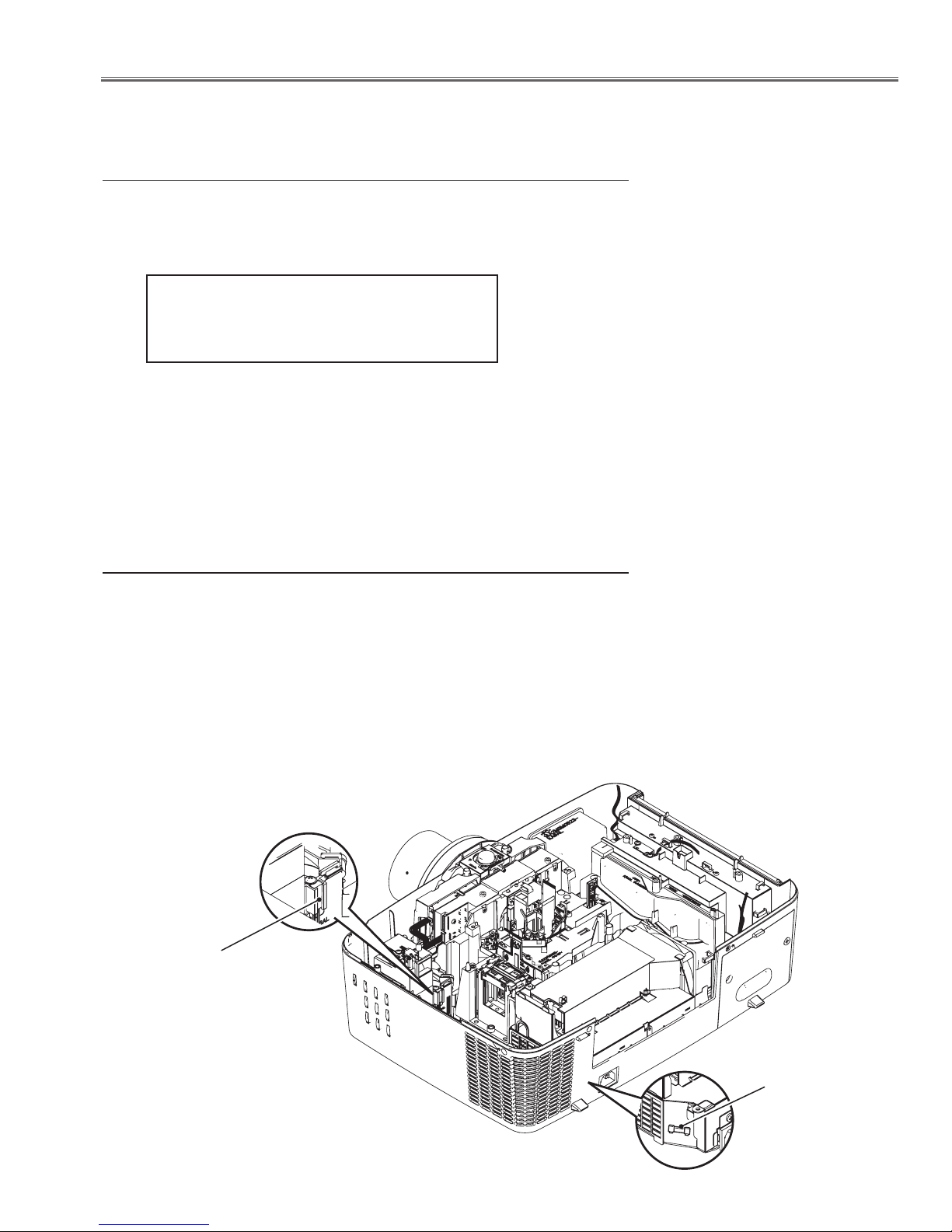
Mechanical sensor switches (SW901, SW1891)
This projector provides 2 mechanical sensor switches, the one is for filter cartridge switch (SW1891) and the other one is for lamp cover switch (SW901).
The filter cartridge switch detects whether the filter cartridge is installed correctly. If the filter cartridge is not installed correctly, the projector cannot turn
on. In this case, the LAMP indicator is lighting and other indicators are blinking.
The lamp cover switch detects whether the lamp cover is closed securely. If
lamp cover is opened or not closed completely, the drive signal to the lamp
circuit is cut off. After opening the lamp cover for replacing the lamp ass’y,
place the lamp cover correctly otherwise the projector cannot turn on. In this
case, the LAMP indicator is lighting and LAMP REPLACE indicator is blinking.
Lamp cover switch
(SW901)
LED indicators
Filter cartridge
Filter cartridge switch
(SW1891)
-6-

Circuit Protections
Temperature sensors, wind sensors
The projector provides 2 temperature sensor ICs, 1 thermistor, and 1 wind sensor on the intake duct. These devices
are monitoring the surrounding temperature of the lamp, panel and intake duct, and the wind sensor is monitoring
airflow passed through the air filter in the intake duct.
- Internal temperature sensor A (IC1692) (around the Intake duct)
- Internal temperature sensor B (IC1816) (around the lamp house)
- Internal temperature sensor C (IC1814) (around the panel/prism)
- Wind sensor D (S901) (intake duct)
S901
Wind Sensor
IC1814 on the
Sensor C Board
IC1816 on the Main
Board (behind)
The projector is shut down and the WARNING TEMP. indicator
is blinking red.
When the temperature inside the projector reaches a certain level,
the WARNING TEMP. indicator starts blinking. If the temperature
rises moreover, the projector will be automatically shut down to protect the inside of the projector, and the WARNING TEMP indicator is
blinking fast and the POWER indicator is blinking. When the projector has cooled down enough (to its normal operating temperature),
the POWER indicator stops blinking and it can be turned on again
by pressing the ON/STAND-BY button.
✔Note:
• The WARNING TEMP. indicator continues to blink even after the
temperature inside the projector returns to normal. When the projector is turned on again, the WARNING TEMP. indicator stops blinking.
IC1692 on the
Sensor A Board
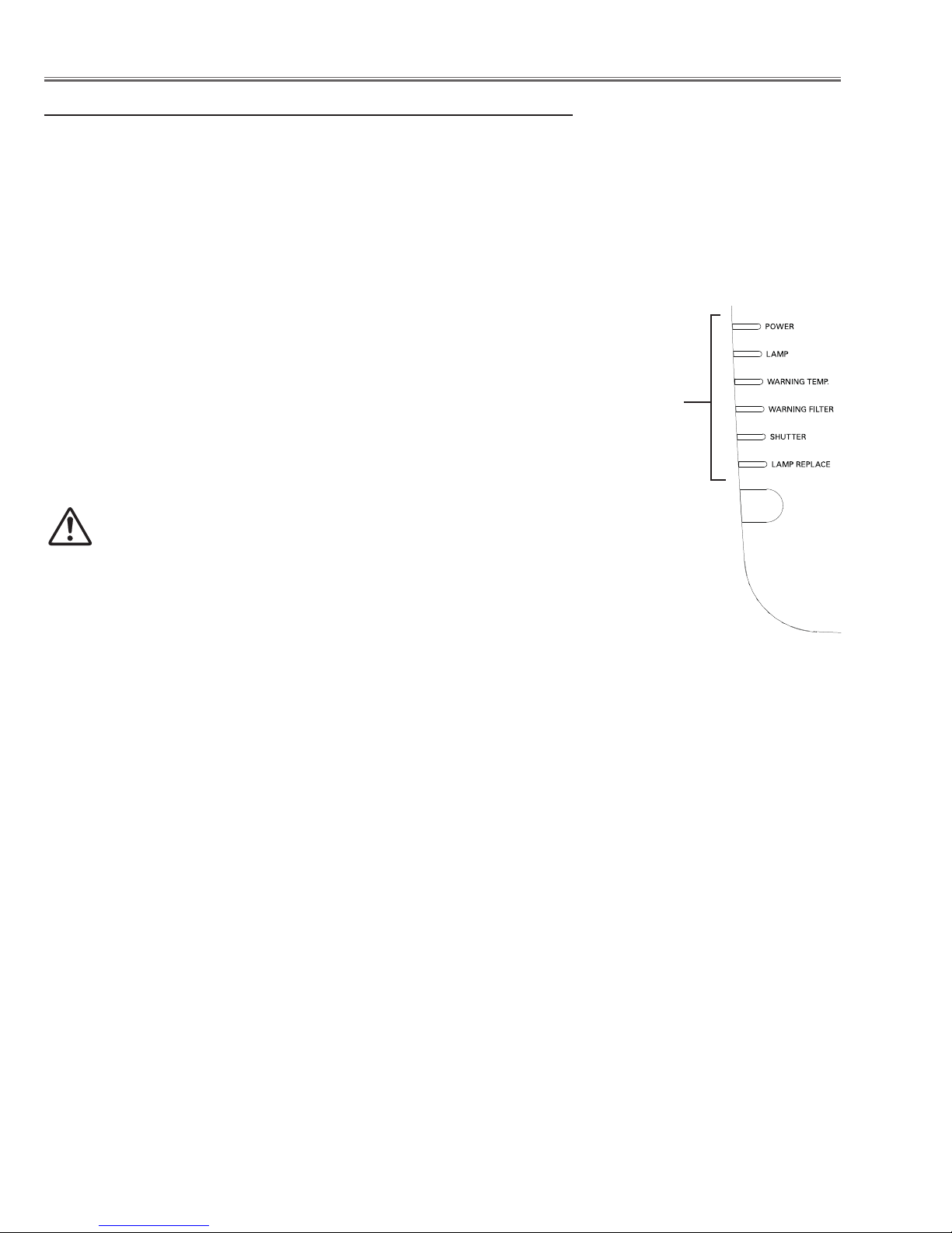
LED indicators
POWER indicator
WARNING TEMP.
indicator
Then check the matters below:
– Did you provide appropriate space for the projector to be ventilated?
Check the installing condition to see if the air vents of the projector
are not blocked.
– Has the projector been installed near an Air-Conditioning/ Heating
Duct or Vent? Move the installation of the projector away from the
duct or vent.
– Is the filter clean? Replace the filter with a new one.
-7-
Circuit Protections
Power failure and fan lock detection
The projector provides the detection circuits of the power failure and the fan lock. When the detection circuit detects
an error at the power supply line or at the fan operation circuit, the projector will turn into the standby mode to protect
the other circuits defective.
The projector is shut down and the LAMP indicator is
lighting and other indicators are blinking.
When the projector detects an abnormal condition, it will be
automatically shut down to protect the inside of the projector
and the LAMP indicator lights on and other indicators blink
In this case, unplug the AC power cord and plug it, and then
turn on the projector once again to verify operation. If the
projector cannot be turned on and these indicators still lighting and blinking, it may operate the power failure protection
function.
Check that the filter cartridge is installed correctly.
CAUTION
DO NOT LEAVE THE PROJECTOR WITH THE
AC POWER CORD CONNECTED UNDER AN ABNORMAL CONDITION. IT MAY RESULT IN FIRE
OR ELECTRIC SHOCK.
LAMP indicator lights on
and other indicators
blink.
LED indicators
-8-
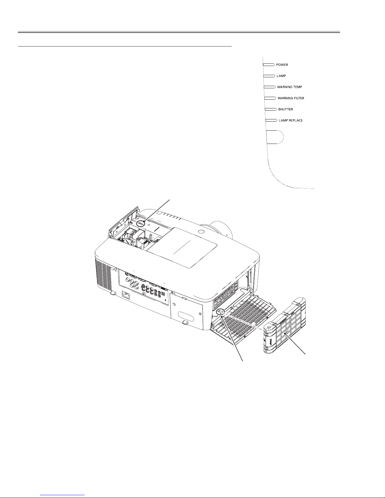
Maintenance
Replacing the Filter Cartridge
Filter prevents dust from accumulating on the optical elements inside the projector. Should the filter becomes clogged
with dust particles, it will reduce cooling fans’ effectiveness and may result in internal heat buildup and adversely
affect the life of the projector. This projector has an electrically operated filter which helps you to replace the filter
easily. The projector monitors the condition of the filter at all time and replaces a filter with a new one automatically
when it detects the clogging.
If the projector detects that the filter is clogged and no scroll is left in the filter cartridge, a Filter cartridge replacement
icon appears on the screen and the WARNING FILTER indicator on the top panel lights up. When you see this icon,
replace the filter cartridge and reset the Filter counter and the Scroll counter.
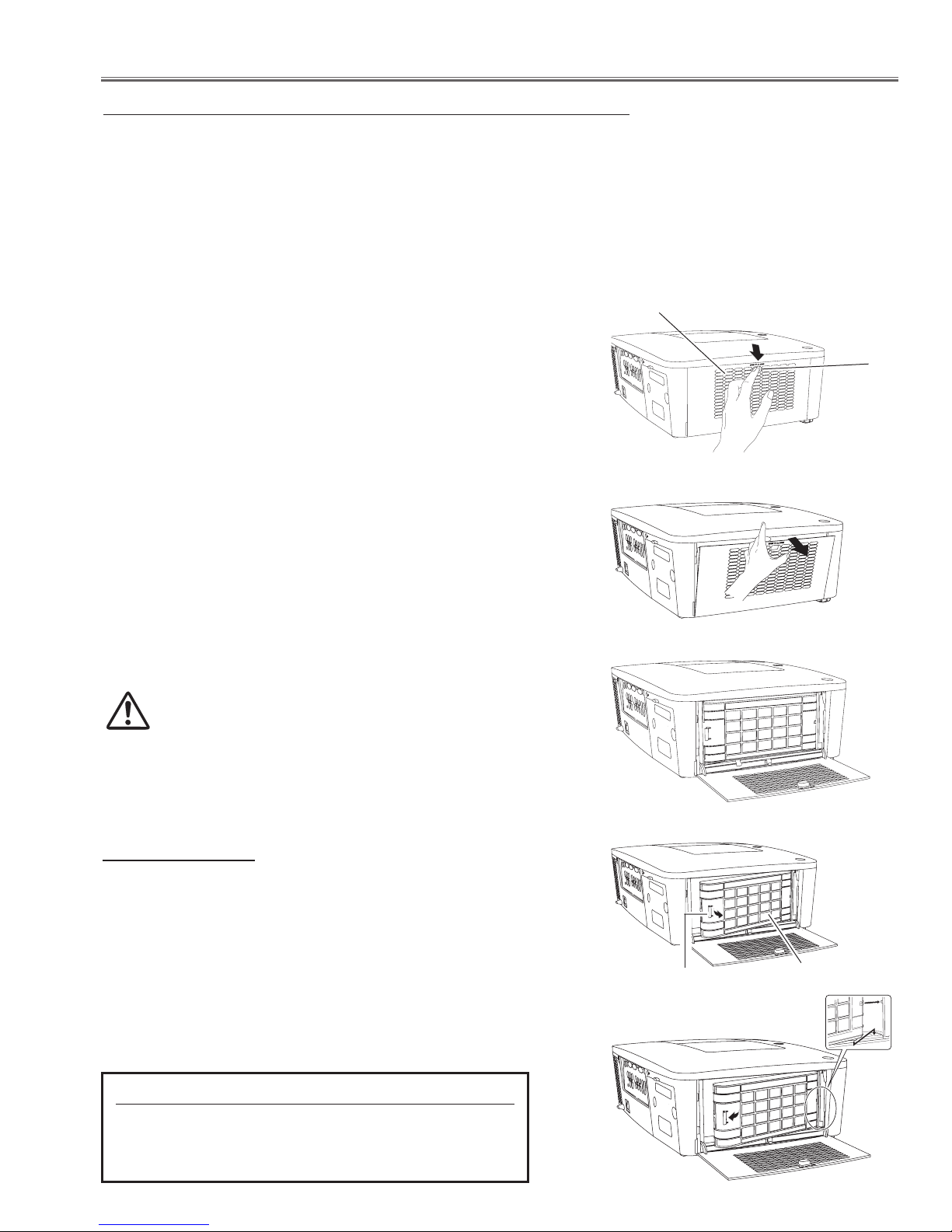
Turn off the projector, and unplug the AC power cord
1
from the AC outlet.
First, clean up the dust on the projector and around the
2
air vents.
Press d downwards on the filter cover to release the
3
latch and open the filter cover.
Pull out the filter cartridge. When taking out the filter
4
cartridge, put your finger on the filter cartridge’s tab and
then pull.
Put the new one back into the position and close the
5
filter cover. Make sure that the filter cartridge is properly
and fully inserted.
Connect the AC power cord to the projector and turn
6
on the projector.
Reset the filter counter and the scroll counter. See
7
next page.
CAUTION
Make sure the filter cartridge is inserted in the
projector. If the filter cartridge is not inserted, the
projector cannot be turned on. Make sure the filter
cover is closed when using the projector.
Do not put anything into the air vents. Doing so may
result in malfunction of the projector.
Filter cover
Latch
RECOMMENDATION
We recommend avoiding dusty/smoky environments
when operating the projector. Usage in these environments may cause a poor image quality.
When using the projector under dusty or smoky conditions,
dust may accumulate on a lens, liquid crystal panels, or optical elements inside the projector. Such condition may degrade the quality of the projected image.
When the symptoms above are noticed, contact your authorized dealer or service station for proper cleaning.
ORDER REPLACEMENT FILTER CARTRIDGE
Type No. POA-FIL-080
Service Parts No.: 610 346 9034
-9-
Tab
Filter cartridge
Maintenance
H
Filter counter 150 H
Timer 400 H
Filter counter reset
Scrolls remaining 9 Scroll(s)
Scroll counter Reset
Scroll counter Reset?
Filter counter 150 H
Timer 400 H
Filter counter reset
Scrolls remaining 9 Scroll(s)
Scroll counter Reset
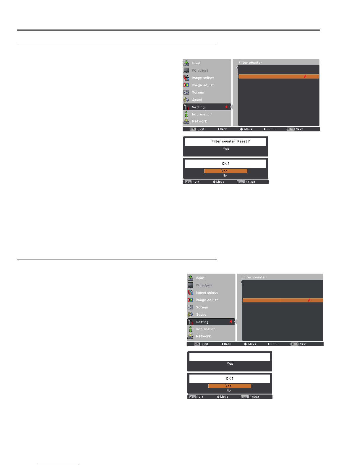
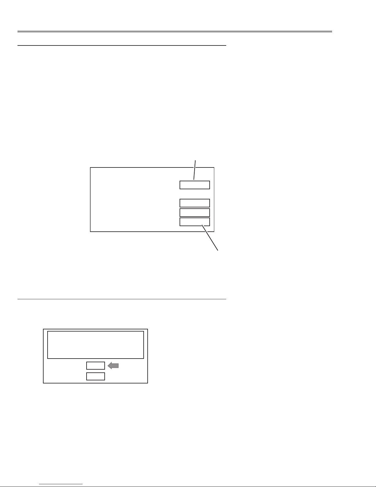
Resetting the Filter Counter
Be sure to reset the Filter counter after replacing the filter
cartridge.
Press the MENU button to display the On-Screen Menu.
1
Use the Point ed buttons to select Setting and then
press the Point 8 or the SELECT button
Use the Point ed buttons to select Filter counter and
2
then press the SELECT button. Use the Point ed but-
tons to select Filter counter Reset and press the SELECT button. Filter counter Reset? appears. Select
[Yes] to continue.
Another confirmation dialog box appears, select [Yes]
3
to reset the Filter counter.
Filter counter
Filter counter
Reset?
Select Yes, then
another confirmation
box appears.
Select Yes again to
reset the Filter counter.
appears.
Resetting the Scroll Counter
Be sure to reset the Scroll counter after replacing the filter
cartridge.
Press the MENU button to display the On-Screen Menu.
1
Use the Point ed buttons to select Setting and then
press the Point 8 or the SELECT button
Use the Point ed buttons to select Filter counter and
2
then press the SELECT button. Use the Point ed but-
tons to select Scroll counter Reset and press the SELECT button. Scroll counter Reset? appears. Select
[Yes] to continue.
Another confirmation dialog box appears, select [Yes]
3
to reset the Scroll counter.
Scroll counter
Scroll counter
Reset?
Select Yes, then
another confirmation
box appears.
Select Yes again
to reset the Scroll
counter.
appears.
-10-
Maintenance
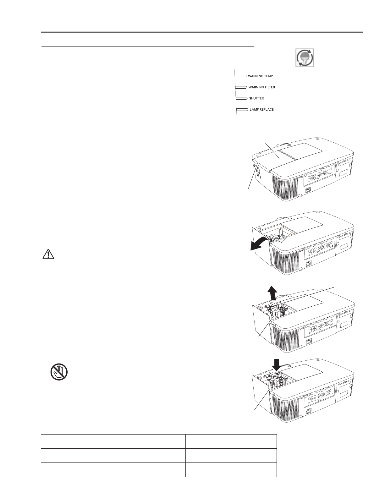
Lamp Replacement
When the projection lamp of the projector reaches its end of life,
the Lamp replacement icon appears on the screen and LAMP
REPLACE indicator lights. Replace the lamp with a new one
promptly. The timing when the LAMP REPLACE indicator should
light is depending on the lamp mode.
Note:
• The Lamp replacement icon will not appear when the Display
function is set to “Off”, or during “Freeze”.
Follow these steps to replace the lamp.
Turn off the projector and unplug the AC power cord. Let
1
the projector cool for at least 45 minutes.
Loosen the screw and slide the lamp cover to open it.
2
Loosen 3 screws of the lamp and pull out the lamp by using
3
the built in handle.
Replace the lamp with a new one. Make sure that the lamp
4
is properly and fully inserted.
Close the lamp cover and secure the screw.
5
Top Panel
Lamp replacement icon
LAMP REPLACE indicator
Lamp cover
Screw
CAUTION
When replacing the lamp because it has stopped illuminating,
there is a possibility that the lamp maybe broken. If replacing the
lamp of a projector which has been installed on the ceiling, you
should always assume that the lamp is broken, and you should
stand to the side of the lamp cover, not underneath it. Remove
the lamp cover gently. Small pieces of glass may fall out when
the lamp cover is opened. If pieces of glass get into your eyes or
mouth, seek medical advice immediately.
For continued safety, replace with a lamp of the same type lamp.
Do not drop the lamp or touch the glass bulb! The glass can shatter and may cause injury.
CAUTION
Allow a projector to cool for at least 45 minutes before you open
the Lamp cover. The inside of the projector can become very
hot.
ORDER REPLACEMENT LAMP
Screws
Handle
Lamp
New Lamp
Model PLC-XM150/PLC-XM150L PLC-XM100/ PLC-XM100L
Type No. POA-LMP136 POA-LMP137
Service Parts No. 610 346 9607 610 347 5158
-11-
Counter
Projector 500H
Lamp
Normal 200H
Eco 300H
Corresponding value 600H
Maintenance
How to check Lamp Used Time
The LAMP REPLACE indicator will light yellow when the total lamp used time (Corresponding value) reaches 3,000
hours. This is to indicate that lamp replacement is required.
The total lamp used time is calculated by using the below expression,
Total lamp used time (Corresponding value) = Teco + Tnormal x 1.5
Teco : used time in the Eco1, Eco2 and Auto mode
Tnormal : used time in the Normal mode and Auto mode
You can check the lamp used time following to the below procedure.
1 Press and hold the ON/STAND-BY button on the projector for more than 20 seconds.
2 The projector used time and lamp used time will be displayed on the screen briefly as follows.
Projector used time
Lamp Total lamp used time
Warning Message on the non-standard lamp used
If the non-standard lamp is used, the warning and confirmation messages will appear on the screen every startup.
Some of the functions are limited when the non-standard lamp is used in spite of the warning.
Since the lamp is not standard,
projector failed to read lamp data.
Continue to use this lamp?
Yes
No
-12-

Maintenance
E
E
D
D
D
E
EE
E
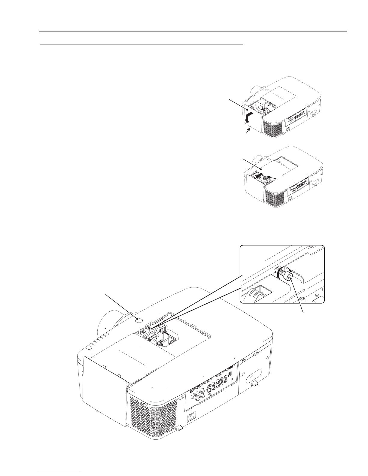
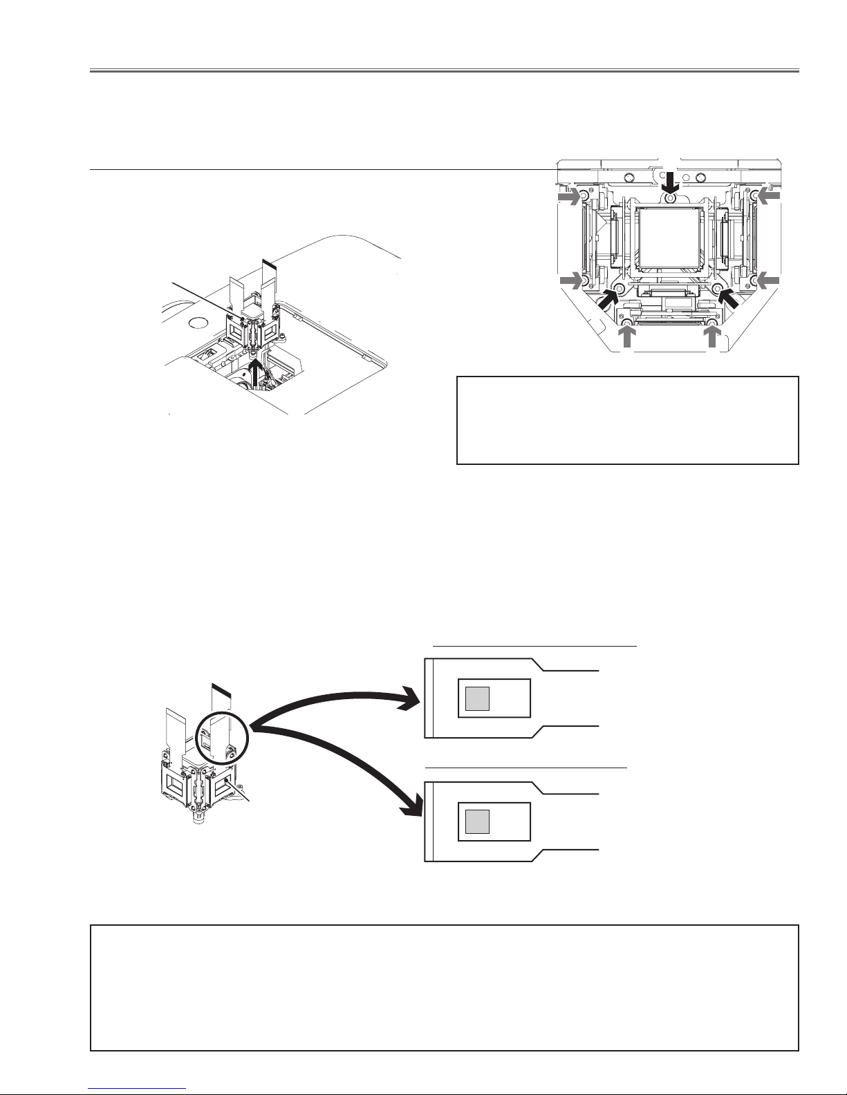
Quick maintenance
This projector provides a cabinet prism cover on the cabinet top to enhance the service maintenance. This enables
service personnel to align the optical adjustment or replace the optical parts without disassembly the cabinet top.
Loosen a screw-A on the lamp cover and slide it to
1
open (Fig. 1).
Lamp cover
Loosen a screw-B on the prism cover and slide it in
2
the arrow direction (Fig. 2).
Loosen a screw-C and take the shutter assembly off
3
(Fig. 3).
Loosen 3 screws-D and take the LCD Panel/Prism
4
ass'y upward off (Fig. 4/Fig. 6).
Remove 2 screws-E on each stopper of the polarized
5
glass ass'y and take the polarized glass ass'y upward
off (Fig. 5/Fig. 6).
See chapter "Optical Parts Disassembly" for further
information of the optical parts disassembly.
Fig. 6
Fig. 1
A
Prism cover
B
Fig. 2
C
Shutter assy
Fig. 3
Setting the Lamp Cover switch to "Service"
When aligning the optical parts with the lamp cover open,
the projector cannot be turned on because the lamp cover
switch is off. Insert the flat screw driver into the opening on
the switch and set the lamp cover switch to "service" position
as shown in the figure below.
After finishing the alignment, make sure that the lamp cover
switch is reset to its original position, and close the prism
cover and lamp cover securely.
Panel/Prism assy
Fig. 4
Lamp cover switch
Polarized glass assy
"Service" position
Fig. 5
-13-
Maintenance
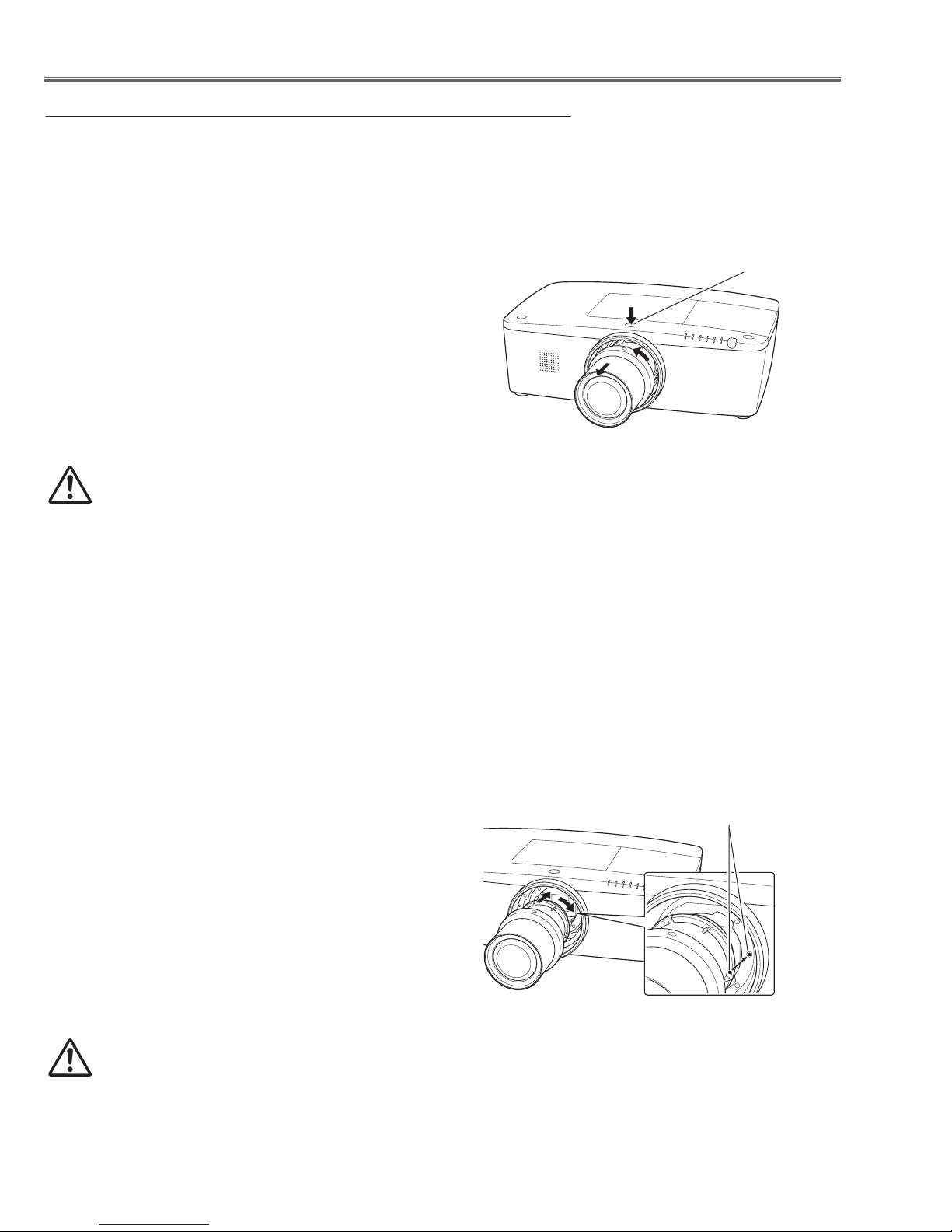
Lens Installation
When replacing the lens or using an optional lens, install the lens by following the instructions below.
Removing the lens
Shift the lens to the center position by using the
1
Lens shift function.
Turn off the projector and unplug the AC power
2
cord.
While pressing the Lens release button on the top
3
of the cabinet, turn the lens counterclockwise until
it stops and pull it out slowly from the projector.
CAUTION
Be careful when handling the lens. Do not
drop.
Lens Release button
Attaching the lens to the projector
Remove the lens mount cover.
1
Fit the lens to the projector by aligning the red dot
2
on the lens with the red dot of the projector.
Slowly turn the lens clockwise until it clicks. Make
3
sure that the lens is fully inserted to the projector.
CAUTION
Do not press the lens release button when attaching the lens.
Red dots
-14-
Maintenance
Using the Lens Antitheft screw
This projector provides a Lens antitheft screw to protect the projection lens stolen from a suspicious person.
Mount the Lens antitheft screw by following the instructions below.
Mounting the Lens antitheft screw
Loosen a screw-A on the lamp cover and slide it to
1
open (Fig. 1).
Loosen a screw-B on the prism cover and slide it in
2
the arrow direction (Fig. 2).
Insert the Lens antitheft screw onto the screw hole
3
on the cabinet top and turn it until the lens release
button is locked (Fig. 3).
Close the prism cover and tighten the screw-B, and
4
close the lamp cover and tighten the screw-A.
Check that the lens release button is locked to protect the projection lens removing.
Note: Be careful not to drop the Lens Antitheft screw
into the opening of the projector when mounting
the screw.
Lamp cover
Prism cover
A
B
Fig. 1
Fig. 2
Lens release button
Lens Antitheft
screw
Fig. 3
-15-

Maintenance
Cleaning
After long periods of use, dust and other particles will accumulate on the LCD panel, prism, mirror, polarized glass,
lens, etc., causing the picture to darken or color to blur. If this occurs, clean the inside of optical unit.
Remove dust and other particles using air spray. If dirt cannot be removed by air spray, disassemble and clean the
optical unit.
Cleaning with air spray
Remove the cabinet top following to “Mechanical Disassembly”. Clean up the LCD panel and polarizing plate by using the air spray from the cabinet top opening.
Caution:
Use a commercial (inert gas) air spray designed for cleaning camera and computer equipment. Use a resin-based
nozzle only. Be very careful not to damage optical parts with the nozzle tip. Never use any kind of cleanser on the
unit. Also, never use abrasive materials on the unit as this may cause irreparable damage.
Disassembly Cleaning
Disassembly cleaning method should only be performed when the unit is considerable dirty and cannot be sufficiently cleaned by air spraying alone.
Be sure to readjust the optical system after performing disassembly cleaning.
1. Remove the cabinet top and main units following to “Mechanical Disassembly”.
2. Remove the optical base top following to “Optical Unit Disassembly”. If the LCD panel needs cleaning, remove the
LCD panel unit following to “LCD panel replacement”.
3. Clean the optical parts with a soft cloth. Clean extremely dirty areas using a cloth moistened with alcohol.
Caution:
The surface of the optical components consists of multiple dielectric layers with varying degrees of refraction. Never
use organic solvents (thinner, etc.) or any kind of cleanser on these components.
Since the LCD panel is equipped with an electronic circuit, never use any liquids (water, etc.) to clean the unit. Use
of liquid may cause the unit to malfunction.
Cleaning the Projection Lens
Unplug the AC power cord before cleaning.
Gently wipe the projection lens with a cleaning cloth that contains a small
amount of non-abrasive camera lens cleaner, or use a lens cleaning paper
or commercially available air blower to clean the lens.
Avoid using an excessive amount of cleaner. Abrasive cleaners, solvents, or
other harsh chemicals might scratch the surface of the lens.
Cleaning the Projector Cabinet
Unplug the AC power cord before cleaning.
Gently wipe the projector body with a soft dry cleaning cloth. When the
cabinet is heavily soiled, use a small amount of mild detergent and finish
with a soft dry cleaning cloth. Avoid using an excessive amount of cleaner.
Abrasive cleaners, solvents, or other harsh chemicals might scratch the
surface of the cabinet.
When the projector is not in use, put the projector in an appropriate carrying
case to protect from dust and scratches.
-16-
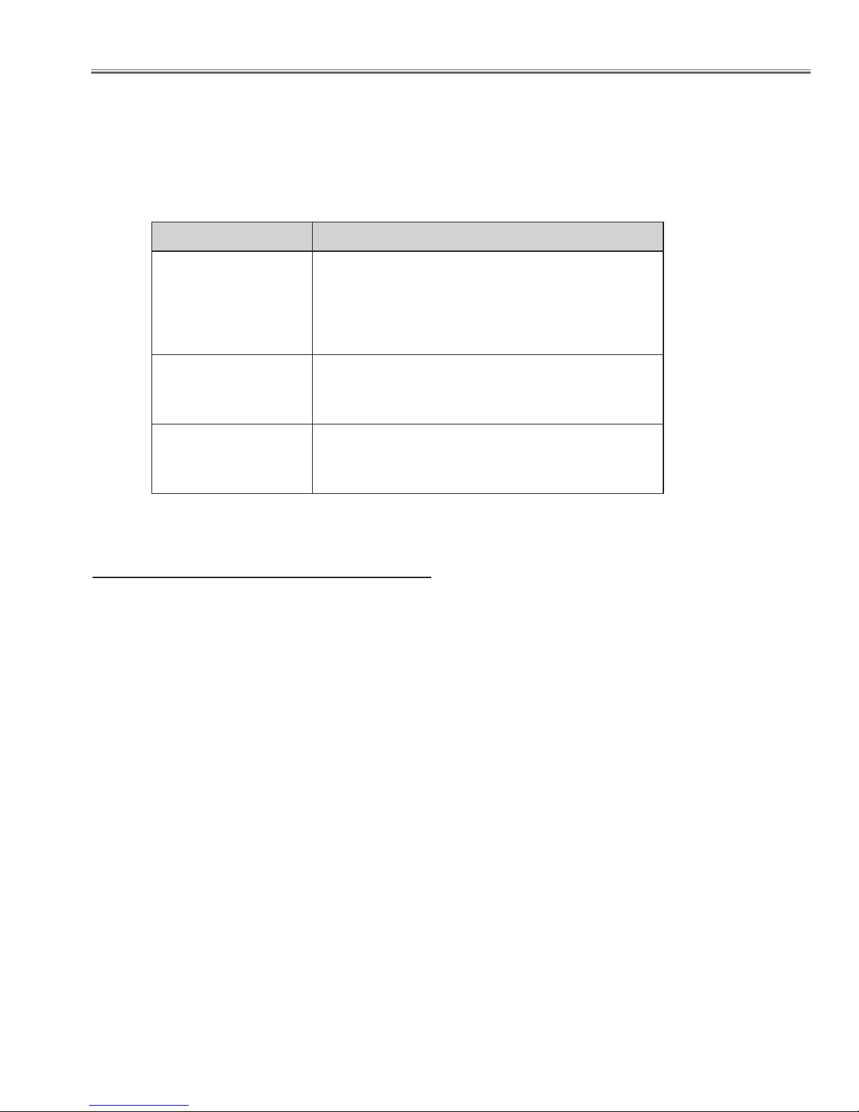
Security Function Notice
This projector provides security functions such as "Key lock", "PIN code lock" and "Logo PIN code lock". When the
projector has set these security function on, you are required to enter correct PIN code to use the projector. If you
do not know the correct PIN code to the projector, the projector can no longer be operated or started. In this case,
you must reset those function first according to the resetting procedure described below and then check up on the
projector.
Function Description
Locks operation of the side control or the remote control.
Key lock
PIN code lock
Logo PIN code lock
If the Key lock is enabled with side control lock, the
projector can no longer be started.
Initial setting: Key lock function is disabled
Prevents the projector from being operated by an unauthorized person.
Initial code: “1234”
Prevents an unauthorized person for changing the
start-up logo on the screen.
Initial code: “4321”
Resetting procedure
1 Disconnect the AC power cord from the AC outlet.
2 As pressing the SELECT button, connect the AC power cord into an AC outlet again.
3 Keep pressing the SELECT button and then press the ON /STAND-BY button.
4 Release the ON/STAND-BY button first and then release the SELECT button.
- The PIN code lock and Logo PIN code lock will be reset as the initial PIN code at the factory and the Key
lock function is disabled.
Please refer to the owner's manual for further information of the security functions.
-17-
Mechanical Disassembly
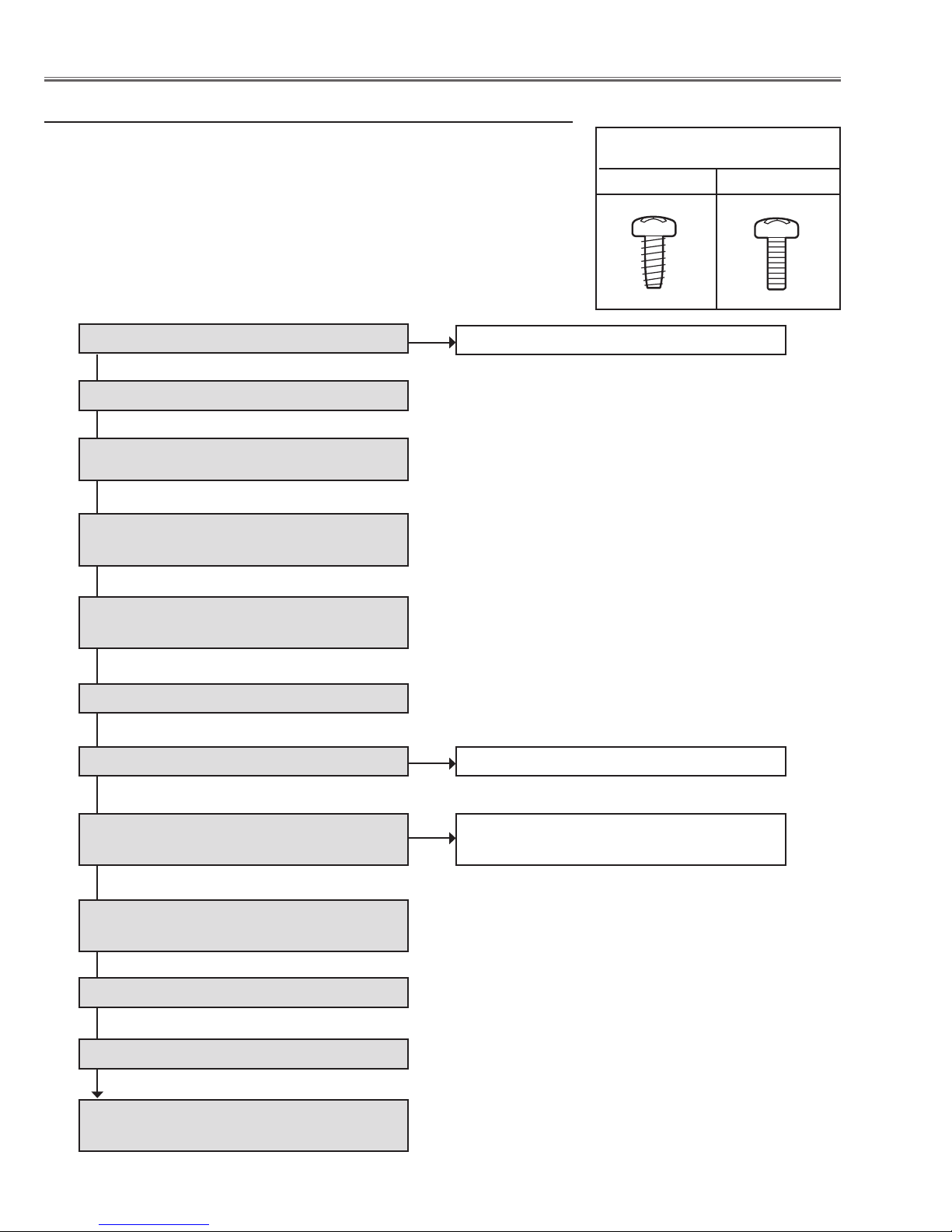
Mechanical disassembly flow chart
Mechanical disassembly should be made by following procedures chart.
Following steps show the basic procedures, therefore unnecessary step may
be ignored.
Caution:
The parts and screws, and the wiring method of the leads and ferrite cores
should be placed exactly the same position as the original otherwise it may
cause loss of performance and product safety.
Screws Expression
(Type Diameter x Length) mm
T type M Type
1. Lamp cover and Prism cover removal
2. Fan (FN905) and Main board removal
3. A/V board removal
4. Shutter, Net Joint and Sensor C board
removal
5. Lamp, Lamp Cover and IC Connect
board removal
6. Projection Lens removal
7. Optical Unit removal
1-1. Cabinet top removal
7-1. Lens Shift assy removal
8. Power Box and Thermal SW (SW902)
removal
9. Control board and Fans (FN902, FN903,
FN904) removal
10. Filter Assy removal
11. Fans (FN908, FN909, FN910) removal
12. Fans (FN906, FN907, FN911) and
Speaker removal
8-1. Power Box disassembly and Fan
(FN901) removal
-18-
Mechanical Disassembly
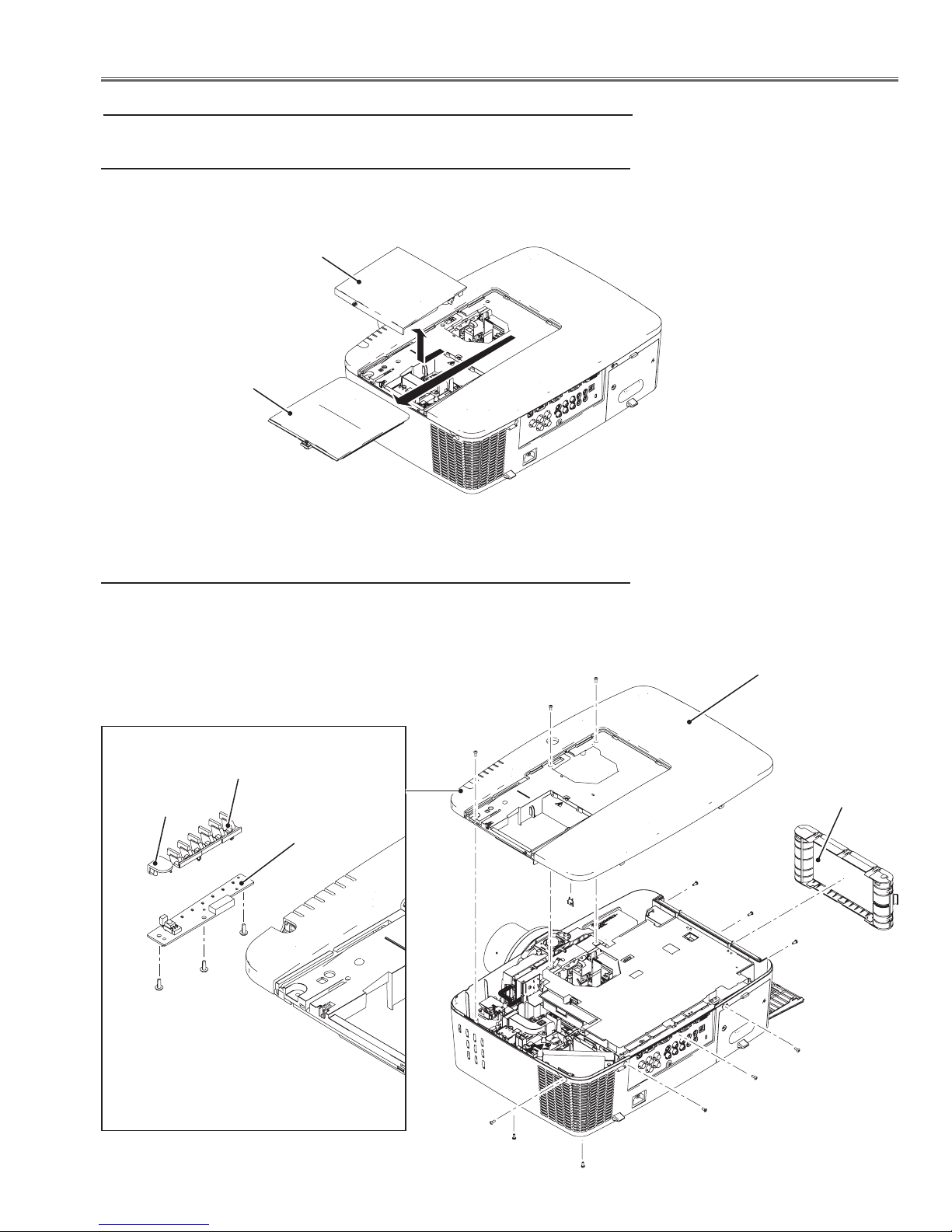
Mechanical disassembly
1. Lamp cover and Prism cover removal
1. Loosen 1 screw-A and remove the Lamp cover upward off.
2. Loosen 1 screw-B and remove the Prism cover by sliding it in the arrow
direction.
Lamp cover
A
Prism cover
B
1-1. Cabinet Top removal
1. Open the filter cover and remove the filter cartridge.
2. Remove 12 screws-A (M3x8) and then take the Cabinet Top Assy upward
off.
A
A
A
LED decoration
RC front
window
T3x8
T3x8
T3x8
F/T RC+LED
board
Cabinet top assy
Filter cartridge
A
A
A
A
A
A
A
A
A
-19-
Mechanical Disassembly
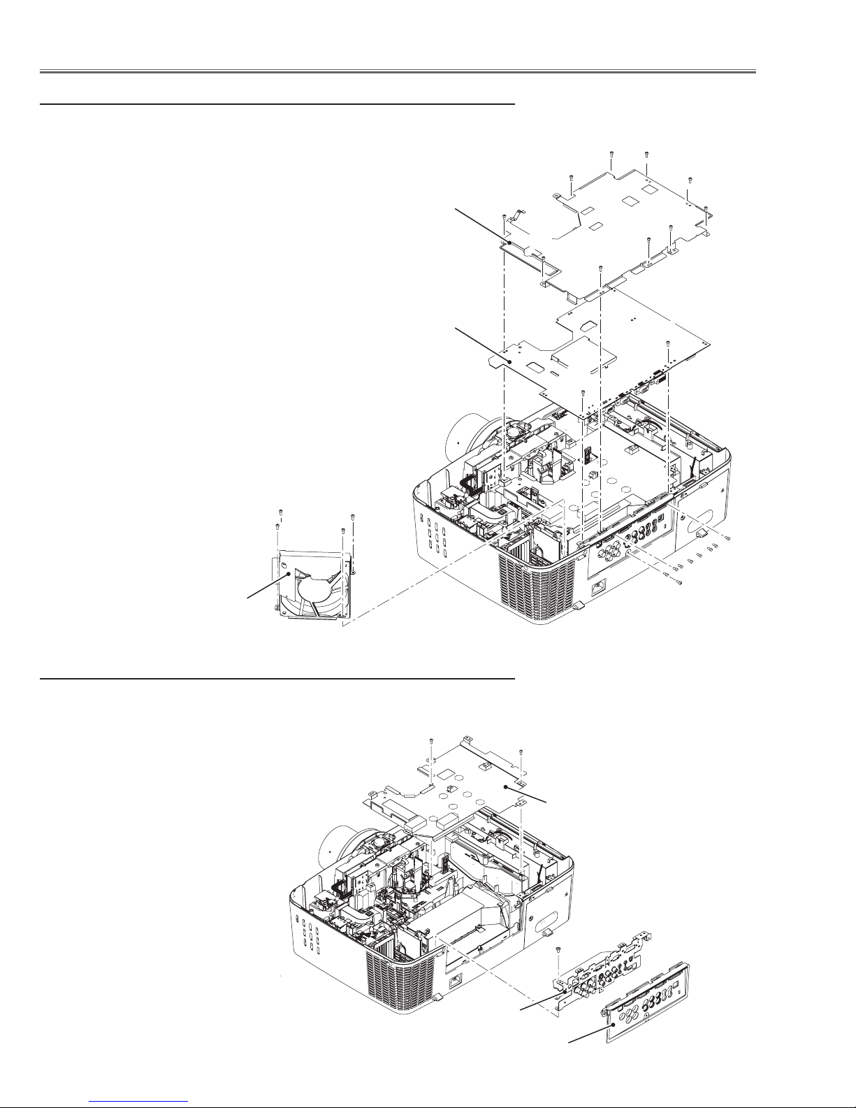
2. Fan (FN905) AND Main board removal
1. Remove 1 screw-A (M3x8) and 3 screws-B (T3x8) to take the Fan (FN905)
upward off.
2. Remove 10 sccrews-C(M3x8) to take the Main board shield top off.
3. Remove 2 screws-D(M3x8) and 8 hex-screws E and 1 screws-F(M3x8)
and then remove the main board.
Main board
shield top
C
C
C
C
C
C
C
C
C
C
Main board
B
B
Fan (FN905)
A
B
3. A/V board and removal
1. Remove 1 screw-A (M4x8) and pull the A/V board assy upward.
2. Remove 2 screws-B (T3x8) to take the Main board shield bottom.
B
D
D
E
F
B
Main board shield bottom
A
A/V board
AV panel
-20-

Mechanical Disassembly
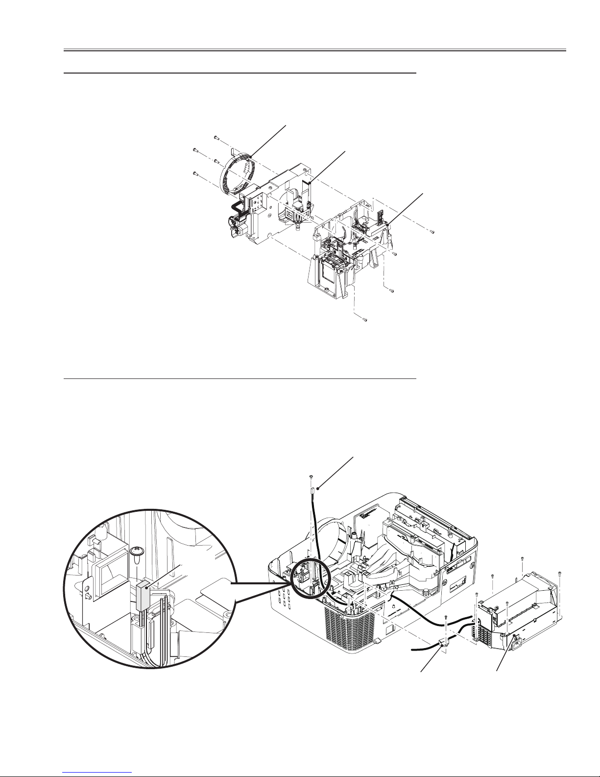
4. Shutter, Net Joint and Sensor C board removal
1. Loosen 1 screw-A and pull the shutter assy upward.
2. Remove 1 screw-B (T3x6) to take the Sensor C board off.
3. Remove 1 screw-C (T3x8) to take the Lamp Cover Switch (SW901) off.
4. Remove 2 screws-D (T3x14) to take the Wind Sensor (S901) off.
5. Remove 2 screws-E (M5x10) to take the Terminal Cover off, and remove
1 screw-F (M4x8) and 1 screw-G (M3x8) and then pull the Net Joint board
assy upward.
Sensor C board
Wind sensor (S901)
Shutter assy
Lamp cover switch
(SW901)
A
B
C
D
G
F
Net Joint board
assy
Terminal cover
5. Lamp, Lamp Cover and IC Connect board removal
1. Loosen 3 screws-A and pull the Lamp assy upward.
2. Remove 4 screws-B (T3x8) to take the Lamp house holder upward off.
3. Remove 2 screws-C (T3x8) to take the ID Connect board.
ID Connect
board
Lamp assy
C
C
A
A
A
B
B
B
B
E
E
T3x8
-21-
Mechanical Disassembly
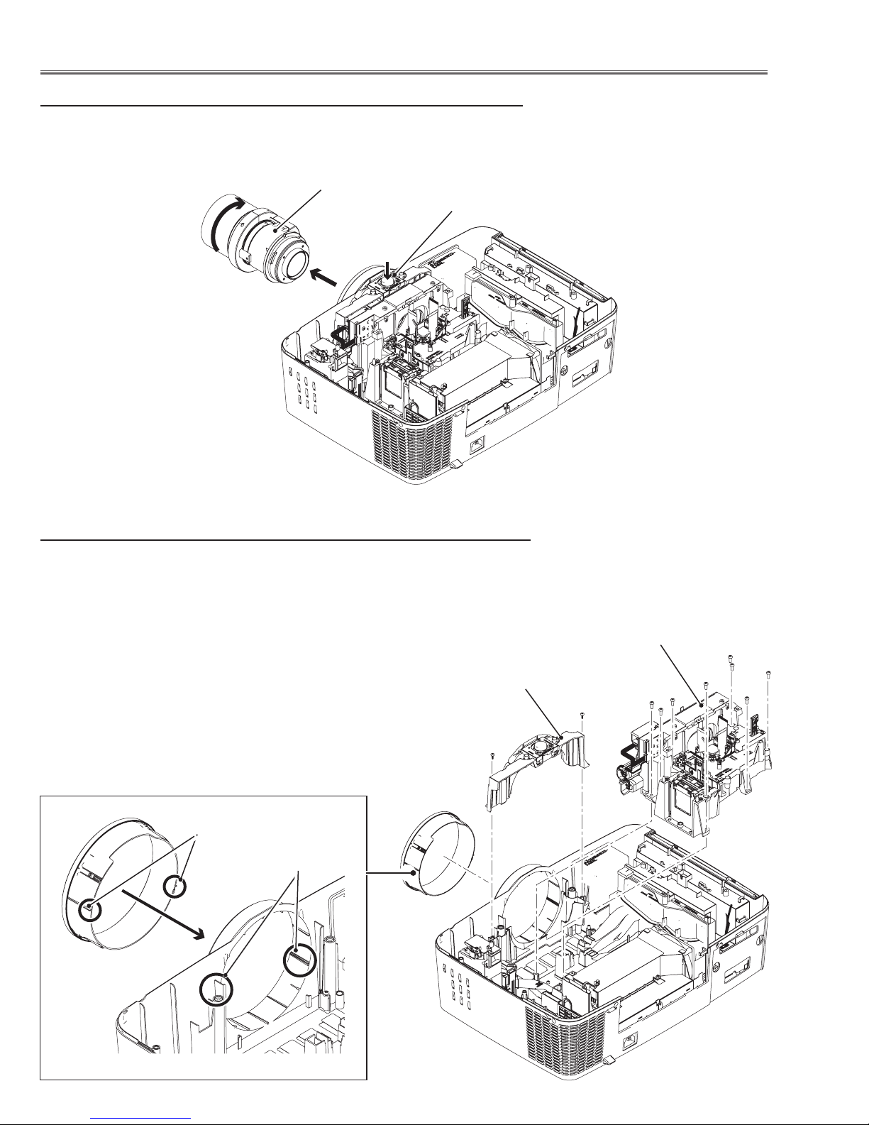
6. Projection Lens removal
1. Press and hold the Lens release button and turn the Projection Lens counterclockwise until it stops and put it out slowly.
Projection lens
Lens release button
7. Optical Unit removal
1. Remove 2 screws-A (T3x8) to take the Lens Cover Top upward off.
2. Remove 8 screws-B (M4x10) and remove the Optical Unit assy and Lens
Shift assy.
3. Remove the Front Ring Cover by pressing it from back.
Lens cover top
A
Guides
Grooves
Optical unit and
Lens shift assy
B
A
B
B
B
B
B
-22-
Mechanical Disassembly
7-1. Lens Shift assy removel
1. Remove 4 screws-A (M3x8) to take the Lens Shift assy off.
2. Remove 4 screws-B (M3x14) to take the Lens Mount off.
Lens mount
B
B
B
Lens shift assy
Optical unit assy
A
A
A
A
8. Power Box and Thermal SW (SW902) removal
1. Remove 2 screws-A (M3x8), 2 screws-B (T3x8) and 1 screw-C (M4x8) and
then remove the Power Box assy.
2. Remove 1 screw-D (T3x8) to take the Trigger Box off.
3. Remove 1 screw-E (T3x8) and pull the SW902 upward off from the groove.
E
SW902
Thermal switch
(SW902)
B
B
A
A
C
D
-23-
Trigger box
Power box assy
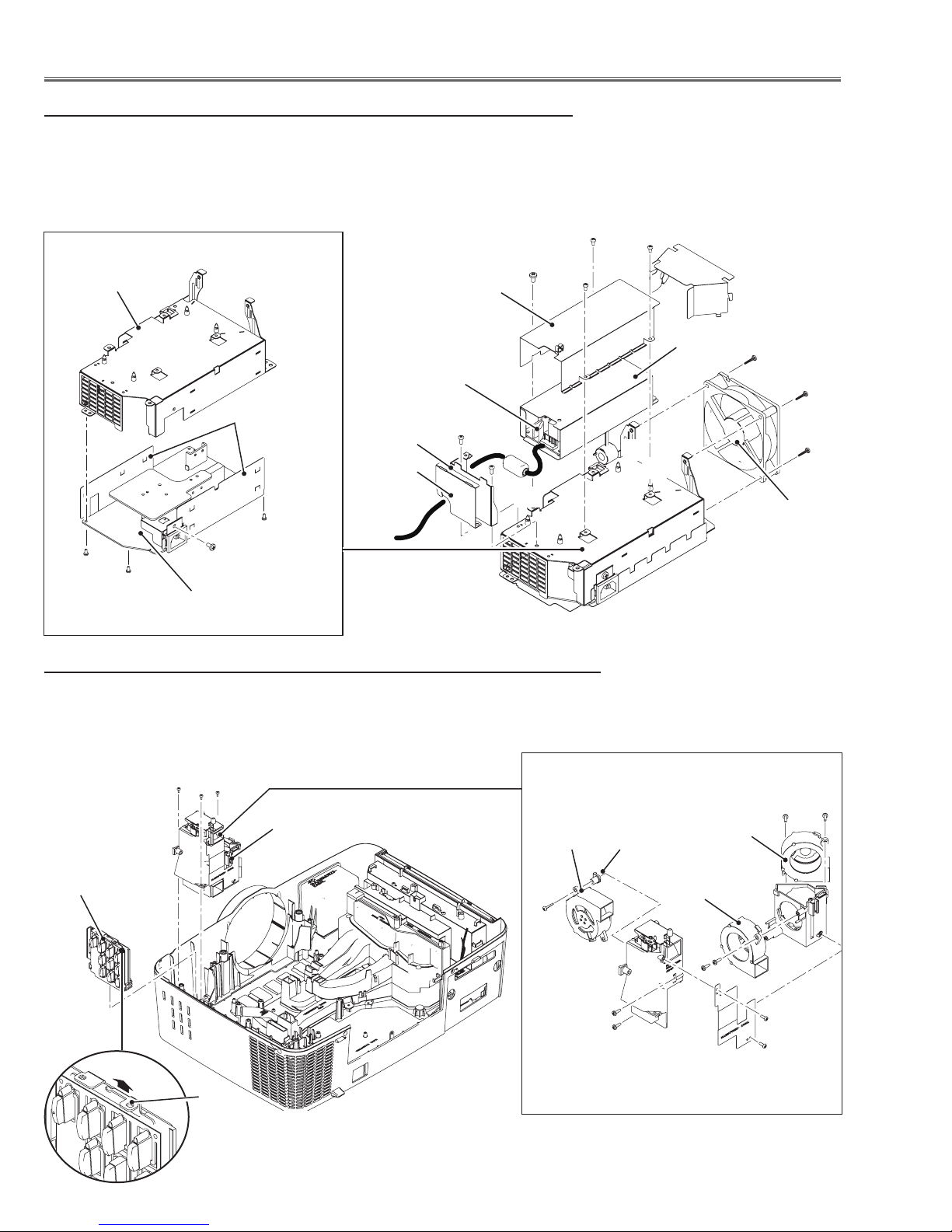
Mechanical Disassembly
8-1. Power Box disassembly and Fan (FN901) removal
1. Remove 1 screw-A (M4x8) and 3 screws-B(M3x8) and remove the Ballast
shield top.
2. Remove 2 screws-C (M3x8) to take the Holder. Unhook the 4 hooks-D and
take the Ballast board off.
3. Remove 3 screws-E (T3x28) to take the Fan (FN901) off.
B
B
Power holder
Spacer
A
Ballast shield top
Ballast Board
C
Holder
B
C
Spacer
D
D
M3x8
M3x8
M3x8
M4x8
Power board
9. Control board and Fans (FN902,FN903,FN904) removal
1. Remove 3 screws-A (T3x8) to take the Lamp fan assy off.
2. Pull the holder on the Control board up to release the hook and remove the
Control board assy upward off.
Spacer
E
E
D
E
D
FN901
A
A
A
Lamp fan assy
Control board assy
Holder
-24-
FN903
T3x22
T3x10
T3x10
Spacer
FN904
T3x10
FN902
T3x10
T3x10
M3x8
M3x8
Mechanical Disassembly
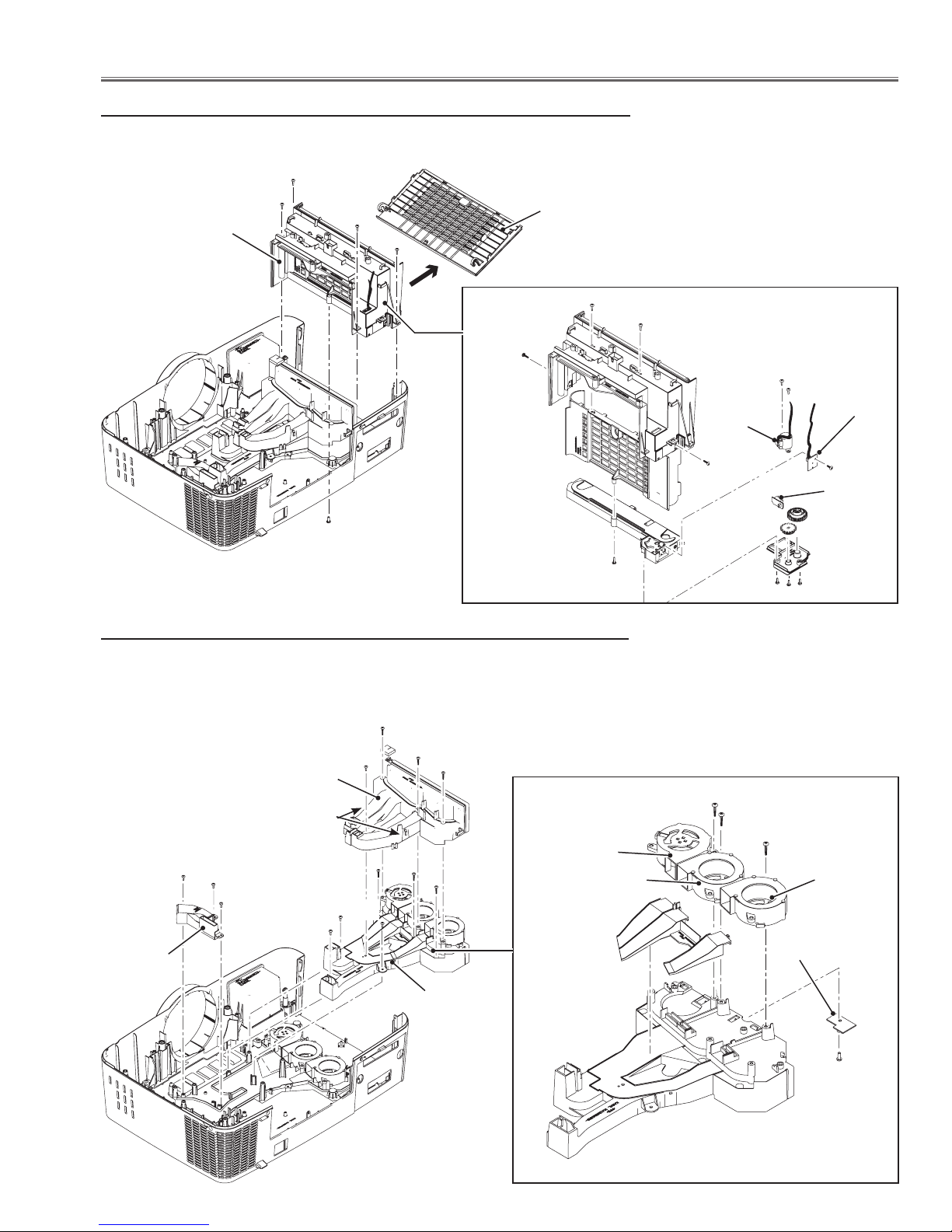
10. A/V Board Assy removal
1. Remove the Filter Cover by pulling it outside.
2. Remove 4 screws-A (T3x8) and 1 screw-B (M3x8) and pull the Filter Box
assy upward off.
Filter box assy
A
A
A
Filter cover
A
T3x8
T3x8
T3x8
B
T3x8
11. Fans (FN908, FN909, FN910) removal
1. Remove 3 screws-A (T3x15), 1 screw-B (T3x8) and unhook 2 hooks and
remove the Duct Panel Top.
2. Remove 3 screws-C (T3x8) to take the Duct PBS off.
3. Remove 3 screws-D (T3x12) and 3 screws-E (T3x8) to take the Duct Fans
assy off.
Duct PBS
Duct panel top
Hook
C
C
C
E
E
A
B
A
A
D
D
D
FN909
FN910
E
FIlter
motor
(M901)
T3x8
T3x12
T3x12
T3x8 x2
T3x12
Sensor A
board
AMF
sensor
board
T3x8
Filter
switch
(SW1891)
T3x8 x3
FN908
Duct fan assy
T3x8
-25-
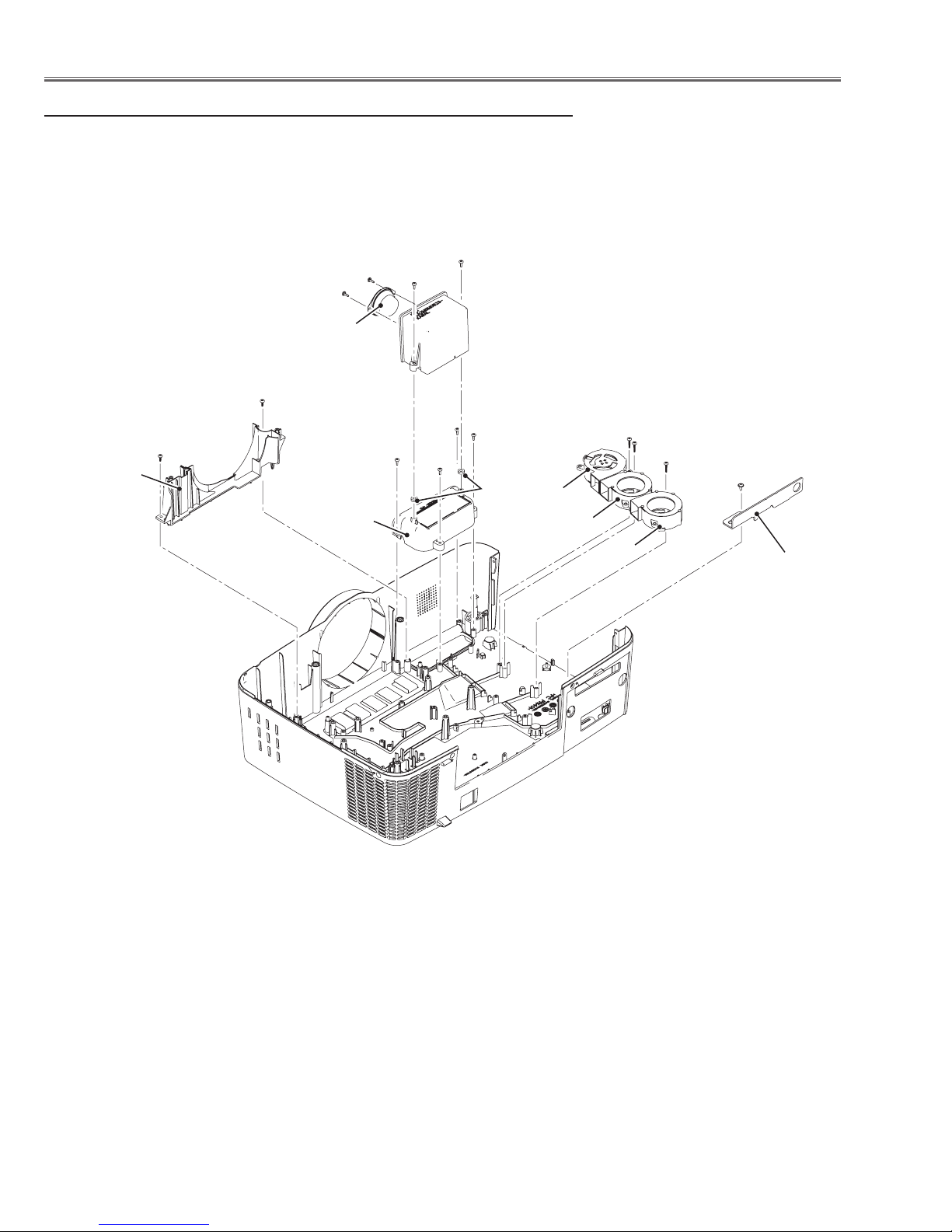
Mechanical Disassembly
12. Fans (FN906, FN907, FN911) and Speaker removal
1. Remove 3 screws-A (T3x12) and remove fans.
2. Remove 2 screw-B (T3x8) to take the Lens Cover Bottom upward.
3. Remove 2 screws-C (T3x8) to take the Speaker box off.
C
T3x8
T3x8
Speaker
B
C
Lens cover
bottom
T3x8
B
Handle cover
T3x8
T3x8
T3x8
Spacer
boss
FN906
FN907
A
FN911
A
A
T3x8
Security holder
-26-
GR
GL
Optical Parts Disassembly
E
E
D
D
D
E
EE
E
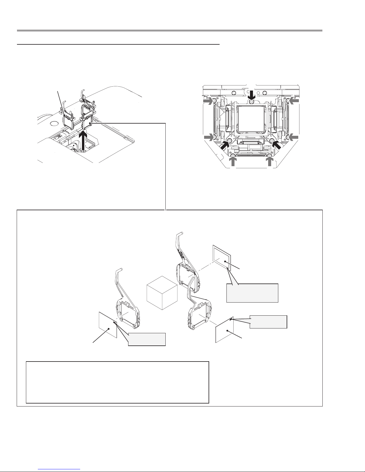
Before taking these procedures, remove the cabinet top, Main board assy, shutter assy referring to the chapter "Mechanical Disassembly".
1. LCD Panel/Prism Assy removal
1. Open the Prism Cover.
2. Loosen 3 screws-D and pull the Panel/Prism assy upward.
Panel/Prism assy
* Note on handling the LCD Panel/Prism Assy
LCD Panel, Polarized glasses are very sensitive parts.
Never touch or wipe the surface. When removing the dust
on the surface, use a commercial (inert gas) air spray to
remove them.
LCD Panel Type Check
There are 2 types combination of the LCD panel/prism assembly and the optical unit, named Type-R and Type-L.
Since both have no compatibility, each type should be combined with the same type, and the specific parts should
be used. If not, the poor optical characteristics may degrade the quality of a projected image.
How to check the type of LCD Panel Ass'y
Check the printed marker on the flat cable of the G-LCD Panel.
GR --> R-type LCD Panel/Prism Ass'y
GL --> L-Type LCD Panel/Prism Ass'y
R-Type LCD Panel/Prism Ass'y
L-Type LCD Panel/Prism Ass'y
G-Panel
IMPORTANT NOTICE on LCD Panel/Prism Ass'y Replacement
LCD panels used for this model cannot be replaced separately. Do not disassemble the LCD Panel/Prism Ass’y.
These LCD panels are installed with precision at the factory. When replacing the LCD panel, should be replaced
whole of the LCD panels and prism ass’y at once.
When replacing LCD Panel/Prism ass’y, take the optical and electrical adjustments following to the chapter "Adjustment".
-27-
Optical Parts Disassembly
E
E
D
D
D
E
EE
E
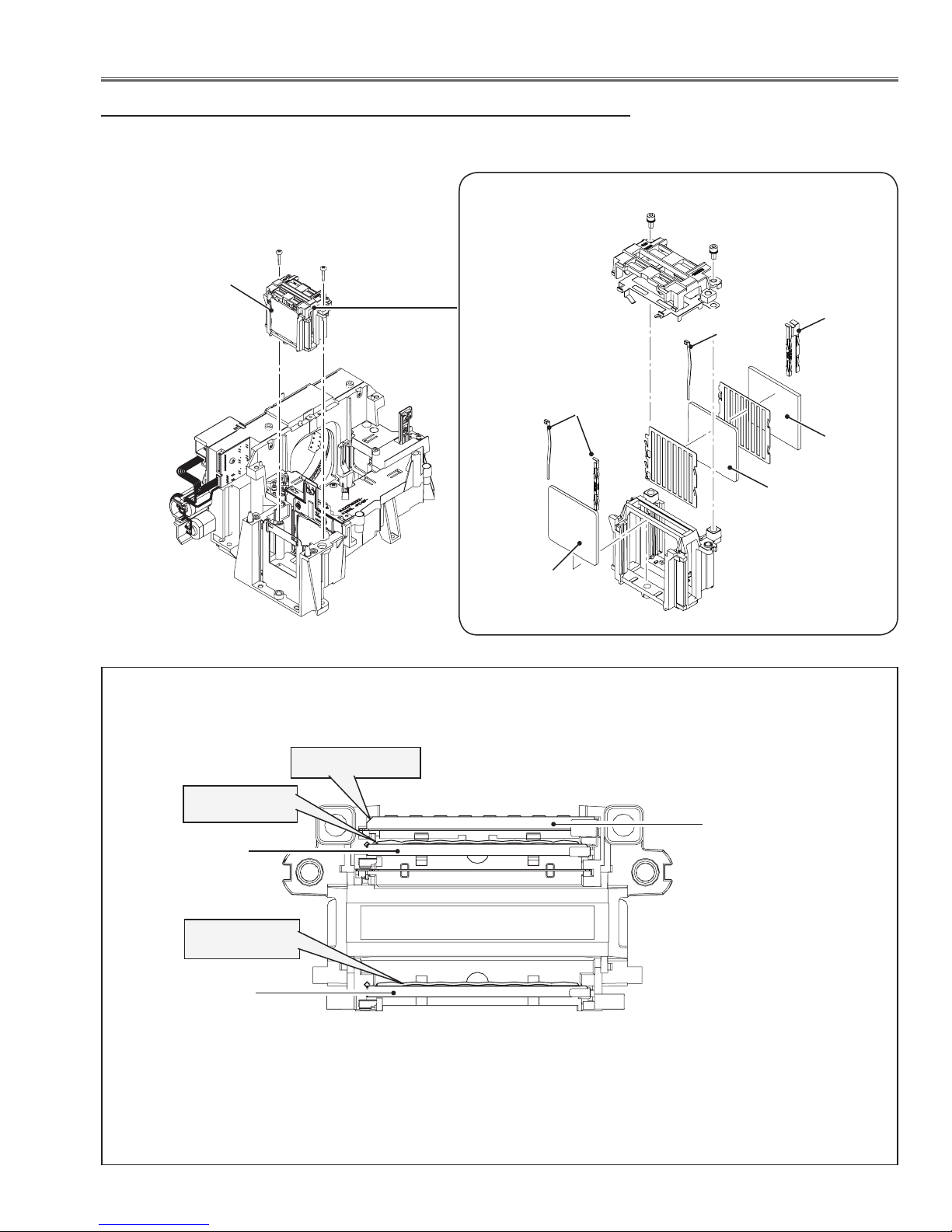
2. Polarized Glass-in removal
1. Remove 2 screws-E (M2.5x6) each on the Polarized glass assy and remove the stoppers, and pull the Polarized Glass assy upward.
Polarized glass assy
Polarized glass-in (R)
Film attached side
comes to this side
Point marker
Point marker
Polarized glass-in (B) *
* Note on handling the polarized glasses
Polarized glass-in (B) and (G) are very sensitive parts. Never touch or
wipe the both surfaces. Grab the edge of the glass by new gloves when
handling the polarized glass. When removing the dust on the surface, use
a commercial (inert gas) air spray to remove them. Never use organic
solvents.
Polarized glass-in (G) *
-28-
Optical Parts Disassembly
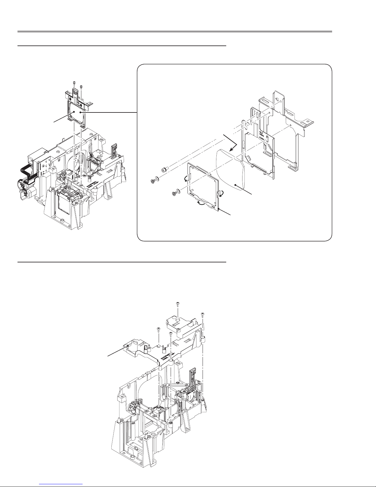
3. PBS and Integrator Lens Assy removal
1. Remove 2 screws-A (M3x14) and pull the PBS and Integrator lens assy
upward.
M2.5x6
PBS and Integrator
lens assy
A
M2.5x6
A
Stopper
Stopper
Stopper
PBS
Integrator
lens-out
Integrator
lens-in
Top view of PBS and Integrator lens assy
Cutting corner
Rugged surface
Integrator lens-out
Rugged surface
Integrator lens-in
PBS
-29-
Optical Parts Disassembly
4. Condenser Lens Assy removal
1. Remove 2 screws-A (M2.5x6) and pull the Condenser Lens Assy upward.
A
A
Condenser lens
assy
M2.5x6
M2x4
M2x4
5. Optical Parts in the Optical Unit removal
1. Remove 4 screws-A (T3x10) to take the Optical Unit Top off.
A
Flat surface
side
Condenser
lens
Stopper
A
Optical unit top
A
A
-30-
 Loading...