

Page 1
Owner’s Manual
Network Set-up and Operation
For Windows
Wired and Wireless Setting
Projector Set-up and Operation
Network Capture
Network Viewer
Moderator Function
This is the manual for the Network function.
Read this manual thoroughly to operate the Network function.
First, read the owner's manual of the projector to understand the basic operation of the
projector and the safety instructions.
The safety instructions in the owner's manuals should be followed strictly.
Page 2

2
Compliance
Federal Communications Commission Notice
This equipment has been tested and found to comply with the limits for a Class B digital device,
pursuant to part 15 of the FCC Rules. These limits are designed to provide reasonable protection
against harmful interference in a residential installation. This equipment generates, uses and can
radiate radio frequency energy and, if not installed and used in accordance with the instructions, may
cause harmful interference to radio communications. However, there is no guarantee that interference
will not occur in a particular installation. If this equipment does cause harmful interference to radio
or television reception, which can be determined by turning the equipment off and on, the user is
encouraged to try to correct the interference by one or more of the following measures:
– Reorient or relocate the receiving antenna.
– Increase the separation between the equipment and receiver.
– Connect the equipment into an outlet on a circuit different from that to which the receiver is
connected.
– Consult the dealer or an experienced radio/TV technician for help.
Model Number : QXXAVC922---P
Trade Name : Sanyo
Responsible party : SANYO FISHER COMPANY
Address : 21605 Plummer Street, Chatsworth, California 91311
Telephone No. : (818)998-7322
This device complies with Part 15 of FCC Rules and RSS-Gen of IC Rules. Operation is subject to the
following two conditions: (1) the device may not cause interference, and (2) the device must accept any
interference, including interference that may cause undesired operation of this device.
CAUTION: Properly shielded a grounded cables and connectors must be used for connection to host
computer and /or peripherals in order to meet FCC emission limits.
VGA cable with ferrite core must be used for RF interference suppression.
For Canadian Users
This Class B digital apparatus complies with Canadian ICES-003.
Cet apparei numérique de la classe B est conforme à la norme NMB-003 du Canada.
FCC Warning
Changes or modifications not expressly approved by the party responsible for compliance could void
the user’s authority to operate the equipment.
FCC RF Exposure Warning
- This transmitter must not be co-located or operated in conjunction with any other antenna or
transmitter.
- This equipment complies with FCC radiation exposure limits set forth for uncontrolled equipment and
meets the FCC radio frequency (RF) Exposure Guidelines in Supplement C to OET65. This equipment
must be installed and operated with at least 20cm and more between the radiator and person’s body
(excluding extremities: hands, wrists, feet and ankles).
Page 3

3
The CE Mark is a Directive conformity mark of the
European Community (EC).
The Alert Mark is a Directive conformity mark of the
European Community.
English
Česky
[Cze ch]
Dansk
[Danish]
Deutsch
[Ger man]
Eesti
[Estonian]
Español
[Spanish]
Ελληνική
[Gree k]
Français
[French]
Italiano
[Italian]
Latviski
[La tvian]
Lietuvių
[Lithuanian]
Nederlands
[Dutch]
Malti
[Maltese]
Magyar
[Hungarian]
Polski
[Polish]
Português
[Portuguese]
Slovensko
[Slovenian]
Slovensky
[Slovak]
Suomi
[Finnish]
Svenska
[Swe dish]
Islenska
[Icelandic]
Norsk
[Norwegian]
Hereby, SANYO Electric Co., Ltd., declares that this WLAN Module (QXXAVC922---P) is in compliance
with the essential requirements and other relevant provisions of Directive 1999/5/EC.
SANYO Electric Co., Ltd. tímto p rohlašuje, že tento WLAN Module (QXXAVC922-- -P) je ve sh odě se
základními požadavky a dalšími příslušnými ustanoveními směrnice 1999/5/ES.
Undertegnede SANYO Electric Co., Ltd. erklærer herved, at følgende udstyr WLAN Module
(QXXAVC922---P) overholder de væsentlige krav og øvrige relevante krav i direktiv 1999/5/EF.
Hie rmit erkl ärt SANYO Elec tric Co., Ltd., dass sich das Gerät WLAN Modu le (Q XXAVC922- --P) in
Übereinstimmung mit den grundlegenden Anforderungen und den übrigen einschlägigen
Bestimmungen der Richtlinie 1999/5/EG bef indet.
Käes olevaga kinnit ab SANYO E lectric Co., Ltd. seadme WLAN Module (QXXAVC922- --P) vastavus t
dir ekti ivi 1999/ 5/EÜ põhin õuetele ja nimet atud dire ktiivis t tu lenev atele teiste le a sjakohas tele
sätetele.
Por medio de la presente SANYO Electr ic Co., Ltd. declara que el WLAN Module (QXXAVC922---P)
cumple con los requisitos esenciales y cualesquiera otras disposiciones aplicables o exigibles de la
Directiva 1999/5/CE.
ΜΕ ΤΗΝ ΠΑΡΟΥΣΑ SANYO Electric Co., Ltd . ΔΗΛΩΝΕΙ ΟΤΙ WLAN Module (QXXAVC922---P)
ΣΥΜ ΜΟΡΦΩ ΝΕΤΑΙ ΠΡΟΣ ΤΙΣ ΟΥΣ ΙΩΔΕΙ Σ ΑΠΑ ΙΤΗΣΕ ΙΣ Κ ΑΙ Τ ΙΣ ΛΟ ΙΠΕΣ ΣΧΕΤ ΙΚΕΣ ΔΙΑΤΑΞΕ ΙΣ ΤΗΣ
ΟΔΗΓΙΑΣ 1999/5/ΕΚ.
Par la présente SANYO Electr ic Co., Ltd. déclare que l’appareil WLAN Module (QXXAVC922---P) est
conforme aux exigences essentielles et aux autres dispositions pertinentes de la directive 1999/5/CE.
Con la presente SANYO Elec tric Co., Ltd. dichiara che questo W LAN Modul e (QX XAVC922- --P) è
conforme ai requisiti essenziali e d alle altre disposizioni pertinenti stabilite dalla direttiva 1999/5/CE.
Ar šo SANYO Electric Co., Ltd., deklarē, ka WL AN Module (QXXAVC922---P) atbilst Direktīvas 1999/5/
EK būtiskajām prasībām un citiem ar to saistītajiem noteikumiem.
Šiuo SANYO Electric Co., Ltd.de klaruoja, kad šis WLAN Module (QXXAVC922- --P) atitinka esminius
reikalavimus ir kitas 1999/5/EB Direkt yvos nuostatas.
Hie rbij verklaa rt SANYO Ele ctric Co., Ltd. dat het toestel WLAN Modul e (QX XAVC922-- -P) in
overeenstemming is met de essentiële eisen en de andere relevante bepalingen van richtlijn 1999/5/
EG.
Hawnhekk, SANYO Electric Co., Ltd., jiddikjar a li dan WL AN Module (QXXAVC922- --P) jikkonforma
mal-ħtiġijiet essenzjali u ma prov vedimenti oħrajn relevanti li hemm fid- Dirrettiva 1999/5/EC.
Alulíro tt, SAN YO Electric Co., Ltd. nyilatkozom, hogy a WL AN Module (QXXAVC922---P) megfelel a
vonatkozó alapvetõ követelményeknek és az 1999/5/EC irányelv egyéb elõírásainak.
Nini ejszym SANYO Elect ric Co., Ltd. o świadc za, ż e WLA N Module (QXXAVC922-- -P) j est zgodny z
zasadniczymi wymogami oraz pozostał ymi stosownymi postanowieniami Dyrekty wy 1999/5/EC.
SANYO Electri c Co. , Ltd . de clara que este (QXX AVC922- --P) está conforme com os r equis itos
essenciais e outras disp osições da Directiva 1999/5/CE.
SANYO Elec tric Co., Ltd. izjavlja, da je ta (QXXAVC922-- -P) v skladu z bistvenimi zahtevami in ostalimi
relevantnimi določili direktive 1999/5/ES.
SANYO Electric Co., Ltd. t ýmto v yhlasuje, že (QXXAVC922-- -P) spĺňa základné požiadavky a všetky
príslušné ustanovenia Smernice 1999/5/ES.
SANYO Elec tric Co., Ltd. vakuuttaa täten että (QX XAVC922---P) tyyppinen laite on direktiivin 1999/5/
EY oleellisten vaatimusten ja sit ä koskevien direktiivin muiden ehtojen mukainen.
Härmed intygar SANYO Electric Co., Ltd. att denna (QXXAVC922---P) står I överensstämmelse med de
väsentliga egenskapskrav och övriga relevanta bestämmelser s om framgår av direktiv 1999/5/EG.
Hér með lýsir SANYO Electric Co., Ltd. yfir því að (QXX AVC922---P) er í samræmi við grunnkröfur og
aðrar kröfur, sem gerðar eru í tilskipun 1999/5/EC.
SANYO Electric Co., Ltd. erklærer herved at utstyret (QXX AVC922- --P) er i samsva r med de
grunnleggende krav og øvrige relevante krav i direktiv 1999/5/EF.
Page 4
4
Safety instructions
CAUTION IN USING THE PROJECTOR VIA NETWORKS
● When you find a problem with the projector, remove the power cable immediately and inspect
the unit. Using the projector with failure may cause fire or other accidents.
● If you remotely use the projector via networks, carry out a safety check regularly and take
particular care to its environment. Incorrect installation may cause fire or other accidents.
CAUTION IN USING NETWORK FUNCTION
● SANYO Electric Co., Ltd. assumes no responsibility for the loss or damage of data, or damage of
the computer caused by using this projector. Making back-up copies of valuable data in your
computer is recommended.
Caution about Radio Wave
This unit operates in 2.4 GHz band, the same frequency band used for industrial, scientific, and medical
equipment (such as pacemaker), as well as amateur radio stations.
Please read “Safety Instructions” section and make sure the following cautions.
1. Be sure that there are no other devices in the area that may use the same frequency band as
Projector.
2. If any other devices are causing radio interferences, change the communication frequency channel
or move to other location.
Trademarks and Copyright
Microsoft, Windows, and Internet Explorer are either registered trademarks or trademarks of Microsoft
Corporation in the United States and/or other countries.
Netscape Navigator and Netscape Communicator are registered trademarks or trademarks of Netscape
Communications Corporation in the United States and other countries.
Pentium is a registered trademark of Intel Corp. in the United States.
Each name of corporation or product in this Owner’s Manual is either a registered trademark or a
trademark of its respective corporation.
Notes
- The contents of this manual are subject to change without notice.
- You may not copy the printed materials accompanying with the software.
- We shall not be responsible for any damages caused by reliance on this manual.
Expression/Abbreviation
The OS of the computer and the Web browser described in this manual is Windows XP Professional and
Internet Explorer 6.0. In case of another OS or Web browser, some instruction procedures may differ
from the actual operation depending on your computer environment.
Use of this manual
This manual does not provide the description of basic operation and functions for computer, web
browser, projector and network. For instructions about each piece of equipment or application
software, please refer to the respective booklet.
Page 5

5
Table of contents
Compliance .........................................................................................................................................................2
Safety instructions ............................................................................................................................................4
Table of contents ...............................................................................................................................................5
Operating environment and configuration .............................................................................................7
Required operating environment for computers .............................................................................. 7
Network specifications of the projector ................................................................................................8
1. About LAN functions ....................................................9
LAN functions and the features ................................................................................................................10
Image projecting system via LAN ............................................................................................................10
An example of the connection .................................................................................................................11
LAN connection modes ...............................................................................................................................12
2. Setup procedures .........................................................15
Installing the software .................................................................................................................................17
3. Names and functions of the operation screen ...........21
Network connection standby display ....................................................................................................22
Network Capture 5 window .......................................................................................................................23
4. Wired LAN configurations ...........................................25
Connecting to the LAN line........................................................................................................................26
Network environment settings.................................................................................................................26
Confirming the operation ...........................................................................................................................28
Network PIN code ..........................................................................................................................................30
Network information ....................................................................................................................................30
Wired factory default....................................................................................................................................30
Wired LAN factory default settings .........................................................................................................31
5. Wireless LAN configurations .......................................33
Setting the network environment ...........................................................................................................34
Setting procedures........................................................................................................................................34
Configuring security with the projector ................................................................................................36
Easy wireless setting .....................................................................................................................................39
Network PIN code ..........................................................................................................................................40
Network information ....................................................................................................................................40
Wireless factory default ...............................................................................................................................40
WIRELESS indicator display ........................................................................................................................41
Wireless LAN factory default settings ....................................................................................................42
6. Basic setting and operation .........................................43
Starting up the Browser ..............................................................................................................................44
Page 6

6
How to use the setting page .....................................................................................................................46
Initial setting ....................................................................................................................................................48
Network configuration ................................................................................................................................51
Configuring wireless LAN setting and security setting....................................................................53
E-mail setting ..................................................................................................................................................55
SNMP setting ...................................................................................................................................................59
7. Controlling the projector ............................................63
Power control and status check ............................................................................................................... 64
Controls .............................................................................................................................................................66
PC adjustment ................................................................................................................................................70
Setting up the projector ..............................................................................................................................71
Timer setting ...................................................................................................................................................74
Projector information ...................................................................................................................................77
Multi-control ...................................................................................................................................................79
8. Network capture functions .........................................85
About Network Capture function ............................................................................................................86
Using the Real Time Capture .....................................................................................................................89
Using the Network Communication .......................................................................................................94
How to use the Network communication ...........................................................................................98
Network Communication operation and change of state ..............................................................101
Executing the forcing mode ......................................................................................................................102
Moderator function ......................................................................................................................................103
Preparation for using the moderator function ...................................................................................104
Using the moderator function ..................................................................................................................105
Moderator's password setting up ............................................................................................................106
Unregister moderator status .....................................................................................................................106
Error information ...........................................................................................................................................107
9. Network Viewer functions ...........................................109
Creating the available data [Network Viewer 5] .................................................................................110
Creating a program file [Program Editor] ..............................................................................................115
Using the Network Viewer function ........................................................................................................120
10. Appendix .....................................................................127
Use of telnet ....................................................................................................................................................128
Web browser setting .................................................................................................................................... 130
Firewall setting ...............................................................................................................................................135
Troubleshooting.............................................................................................................................................136
Terminology.....................................................................................................................................................142
Page 7

7
Operating environment and configuration
Required operating environment for computers
When operating the projector via the networks, computers should meet the operating environment
below.
Microsoft Windows 2000 or
OS
CPU
Microsoft Windows XP or
Microsoft Windows Vista (32bit version)
Pentium 3 ; 1GHz or higher
(more than 2GHz is recommended) for Windows 2000
or Windows XP
Pentium 4 ; 3GHz or higher for Windows Vista
Memory
Free HDD Space 100MB
Screen Resolution
Communication Protocol TCP/IP
Network
Correspond
Browser Application
Wireless LAN Correspond to IEEE802.11b/g
Wired LAN
256MB or more for Windows 2000 or Windows XP
1GB or more for Windows Vista
Required to support any of VGA (640 x 480), SVGA
(800 x 600), XGA (1024 x 768),
The color number should be either 16 bit (65536
colors) or 24/32 bit (16.77 million colors).
Correspond to 100BASE-TX (100Mbpd)
/10BASE-T (10Mbps)
Microsoft Internet Explorer Ver.4.0 or later
Netscape Communications Netscape Communicator
Ver.6.0 or later
Page 8

Network specifications of the projector
LAN Terminal
Data communication speed 100Base-TX (100Mbps)/10Base-T (10Mbps)
Protocol TCP/IP
Wireless LAN
Interface IEEE802.11b/g
Compliance
Communication Mode
Data Transfer Speed
Wireless Frequency (Channel) 2412MHz–2462MHz (CH1–CH11)
Modulation Form
Protocol TCP/IP
Security
Service area
Countries and Standards
AdHoc,
Infrastructure
1/2/5.5/11Mbps (IEEE802.11b)
6/9/12/18/24/36/48/54Mbps (IEEE802.11g)
IEEE802.11g OFDM
54/4Mbps 64QAM, 36/24Mbps 16QAM, 18/12Mbps
QRSK, 9/6Mbps BPSK
IEEE802.11b DSSS
11/5Mbps CCK, 2Mbps DQPSK, 1Mbps DBPSK
WEP 64Bit (Open/Shared) /WEP 128Bit (Open/Shared),
WPA-PSK(TKIP), WPA2-PSK(AES),
SSID, ESSID
about 30 m (without disturbance)
Differs according to the operating environment.
JAPAN: VCCI ClassB,TELEC (Wireless)
USA: FCC Part15 Subpart C (Wireless)
FCC Part15 Subpart C, Class B
Canada: IC RSS-210 (Wireless), IC ICES-003 ClassB
Europe: R&TTE, EMC, LVD
8
Page 9

9
1. About LAN functions
This chapter describes the features, the mechanism,
and connection procedures of the LAN.
Chapter
1
9
Page 10

10
Chapter 1 About LAN functions
LAN functions and the features
This product is loaded with a LAN network function which enables you to project an image on the
computer through a projector via Network with dedicated software.
With the software, you can also manipulate the projecting image and the projector.
This software has functions below and you can use the projector under various network environments
to meet the wide-ranging needs of the operation.
• Accept both Wired and Wireless LAN environment. When the projector is operated via Wireless LAN,
there is no need for wire connection.
• Remove the burden of LAN settings. Easy LAN setting function is provided.
• One computer image can be projected up to 5 projectors simultaneously.
• Network capture function to project the computer's screen image through the projector.
• Remote function which allows you to operate the projector from a distance.
• Monitoring function for the projector operation.
• E-mail function which reports the operating status to your maintenance management.
• Network viewer function which remotely operates the image data on the server to project through
the projector.
• Moderator function with which the moderator can project the image on the participants’ computer
screen at the meetings or the classes.
• Multi control function which can operate multiple projectors (up to 100) simultaneously.
Image projecting system via LAN
The images are projected through an image capturing system which helps to project the faithful
computer images. With this system, you can use the product under various application environments
despite the differences of application software.
Flow of Image Transfer
1. Download the computer image with the dedicated software faithfully to the real image.
2. The downloaded data will be compressed to the digital signal and transferred to the projector via the
LAN (Wired or Wireless). (One computer can operate up to 5 projectors simultaneously.)
3. Digital signal will be reproduced into RGB image signal and will be projected by the projector.
✳ The image will be transferred to each projector. The time lag can occur between each projection.
CAUTION: This product does not correspond to the application with DirectX, MSOffice assistant, and video replay such as DVD.
Page 11
11
0.0
0.5
1.0
1.5
2.0
0.0
0.5
1.0
1.5
2.0
0.0
0.5
1.0
1.5
2.0
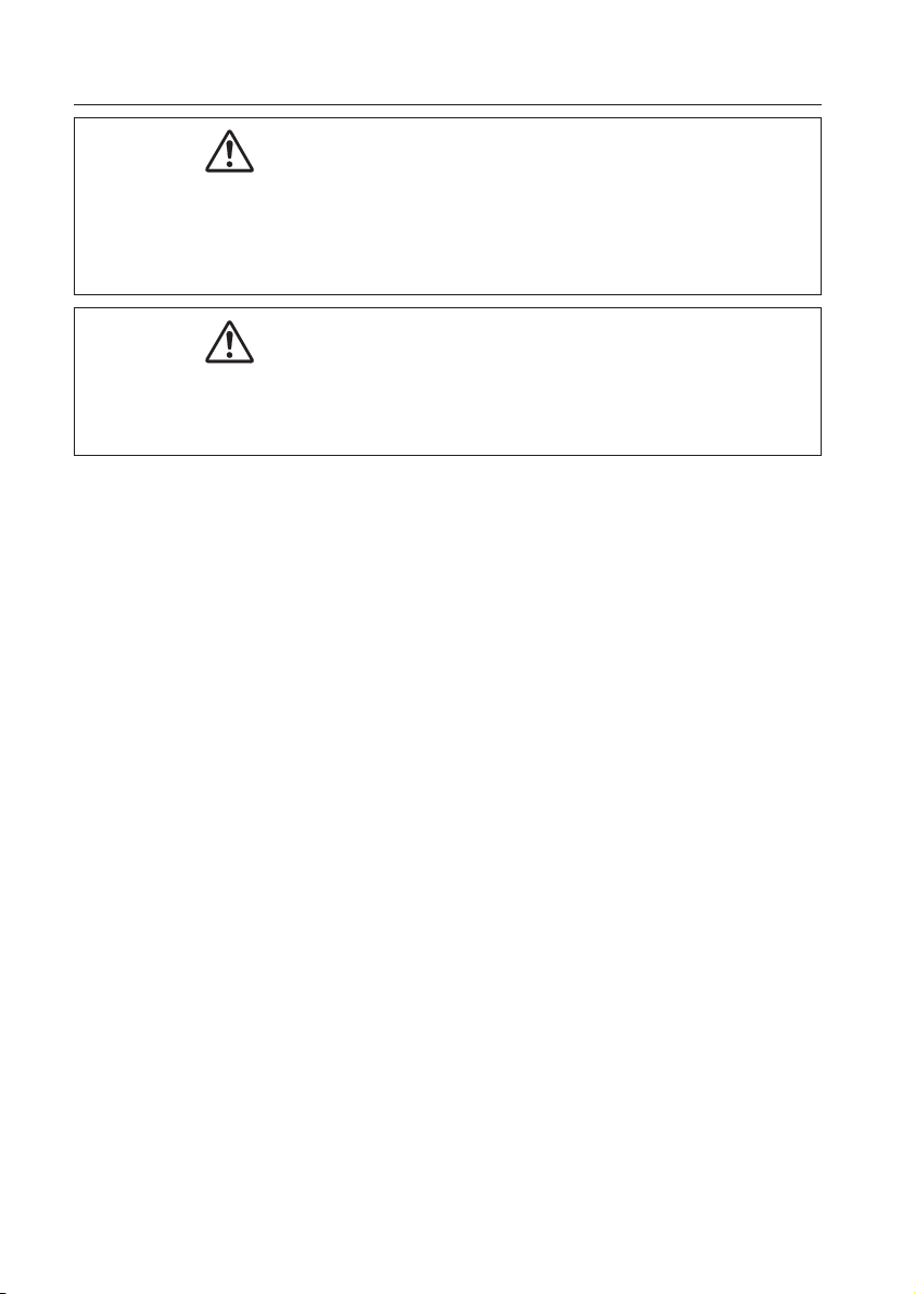
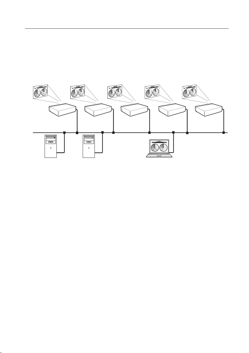
An example of the connection
An example of the connection
The illustration below shows an example of the projection via the LAN.
You can project the image on Computer (1) (Wired LAN connection), or Computer (2) (Wireless LAN
connection) through the selected projector .
Access pointComputer (1)
Computer (2)
Page 12
12
Chapter 1 About LAN functions
LAN connection modes
Connection modes differ depending on the LAN and computer environments.
Connect appropriately for each environment.
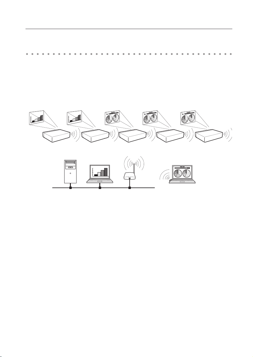
■ Wireless LAN, Infrastructure Communication Mode
Communicate over an access point between Wired LAN equipment and Wireless LAN equipment. Or,
communicate over an access point among multiple Wireless LAN equipment. Wireless LAN equipment
will select an access point to communicate SSID/ESSID modes. These communication modes are used
when both Wireless LAN and Wired LAN are used in the same network environment.
Computer (2)
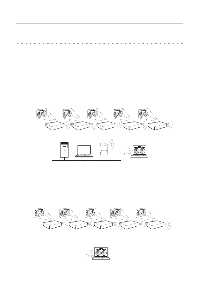
■ Wireless LAN, AdHoc Communication Mode
Communication mode between Wireless LAN equipment.
(Communication mode via SSID/ESSID)
Wireless communication mode corresponded
computer: AdHoc
Access pointComputer (1)
Network Projector
Wireless communication mode :AdHoc
Wireless communication mode
corresponded computer: Infrastructure
Page 13
13
LAN connection modes
■ Wired LAN Communication Mode
Communicate via the LAN line.
Computer(1) Computer(2) Computer (3)
✳ Operate the computer mouse with the remote control.
When the projector’s remote control employs mouse operating function, you can operate the
computer by the remote control. To use the remote control, point to the projector. You do not
need to connect the USB cable to operate the computer mouse.
(The remote control which is provided with the projector does not have the mouse operating
function.)
Page 14

14
Chapter 1 About LAN functions
Page 15

15
2. Setup procedures
This chapter describes how to install the Network
Capture 5 software and how to set up the networks.
Chapter
2
15
Page 16

16
Chapter 2 Setup procedures
To use the projector via the networks, follow the setup procedures below.
STEP 1
STEP 2
STEP 3
Install the software on computers.
Install the software recorded in CD-ROM on each computer which will be operated.
Read following pages of this chapter to install.
Select Wired LAN or Wireless LAN then connect the
LAN and set the configuration.
Decide depending on the LAN environment.
Wired LAN ............ Refer to “4. Wired LAN Configurations” (pp.25–31).
Wireless LAN ....... Refer to “5. Wireless LAN Configurations” (pp.33–42).
Detailed LAN configurations need to be done with a browser later.
First, complete the Wired or Wireless LAN connection between computers and
projectors, then start browser configurations.
➔ “6. Basic setting and operation” (pp.43–62).
Network Configuration has completed.
Follow each chapter to project an image and operate the projector.
■ Operate and manage the projector ➔ “7. Controlling the projector” (pp.63-84)
➔ “Power Control and status check” (p.64)
➔ “Controls” (p.66)
➔ “PC adjustment” (p.70)
➔ “Setting up the projector” (p.71)
➔ “Timer setting” (p.74)
➔ “Projector information” (p.77)
➔ “Multi-control” (p.79)
■ Project an image on the computer ➔ “8. Network capture functions" (pp.85-108)
➔ “Use of real time capture” (p.89)
➔ “Use of network communication” (p.94)
➔ “Moderator function” (p.103)
■ Project an image on a network server ➔ “9. Network Viewer functions” (pp.109-126)
➔ “Create the available data” (p.110).
➔ “Create the program files” (p.115).
➔ “Project the image with network viewer function” (p.120)
* Even if Network Capture 5 is not installed into the computer, the wireless LAN can be set up with USB memory. (p.93)
Page 17
17
Installing the software
Installing the software
It is required to install the software into your computer to use the Network Capture function . Please
install the software as follows.
Note: To install the software into the computer with Windows 2000, Windows XP or Windows
Vista, you should logon as administrator. Before installation, make sure that the other
applications are closed, otherwise proper installation cannot be made.
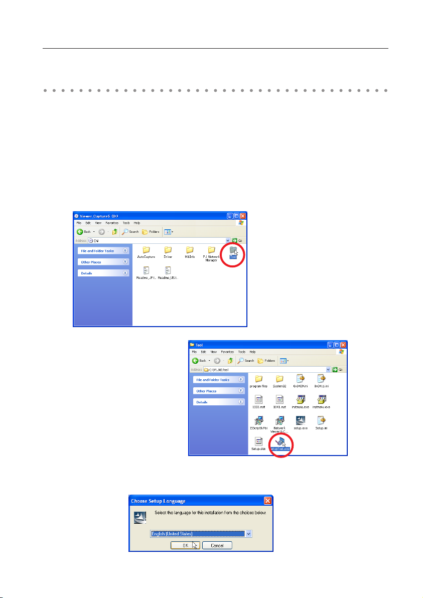
Network Viewer & Capture 5 installation
1 Set the supplied Network Viewer & Capture 5 CD-ROM into the CD-ROM drive of your computer.
Double click SetupTool.exe icon in the "Tool" folder in the CD-ROM.
2 Select "English [United States]" from the pull-down menu on the "Choose Setup Language" window
and click OK button to start installing and then follow the installation wizards.
Page 18
18
Chapter 2 Setup procedures
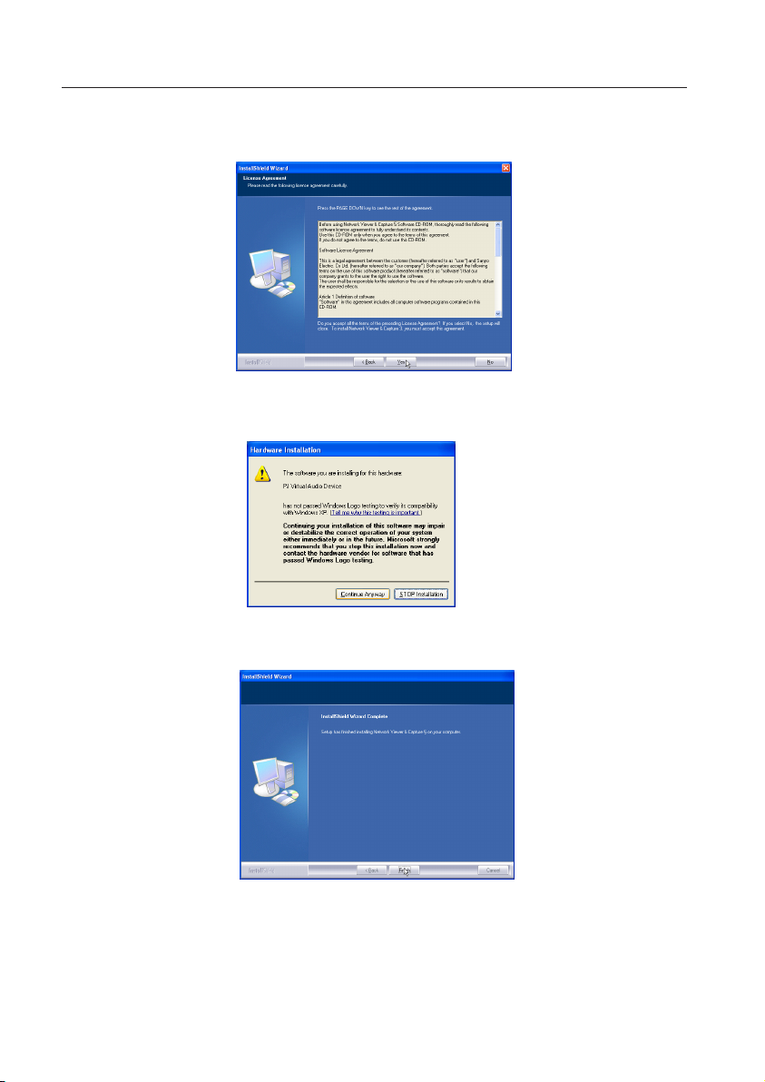
As the "License Agreement" will appear, read contents carefully and click Yes button if you agree to
the license agreement to proceed with installing.
During the installation, following window may appear, click Continue Anyway button.
3 Click Finish to complete the installation.
Page 19
19
Installing the software
Installed software
The following 3 softwares are installed on your computer.
● Network Capture 5:
Captures the displayed image and the sound of the computer and serves them to the projector via
the network.
● Network Viewer 5 (File Converter 1):
Converts to the JPEG*1 data format which can be projected with the projector from the JPEG, bitmap
and Power Point files.
● Network Viewer 5 (Program Editor) :
This is a tool to make the program which has a function to specify and order the projecting JPEG
image data stored in the file servers.
* To uninstall these software, use "Add/Remove Program" from the control panel.
*1 This product supports the JPEG image format. This file is needed to convert to the optimized JPEG file by using the
File Converter 1 software previously. Refer to the item "Creating the available data [Network Viewer 5]"(+ p.110)
about data converting for the projection.
Page 20
20
Chapter 2 Setup procedures
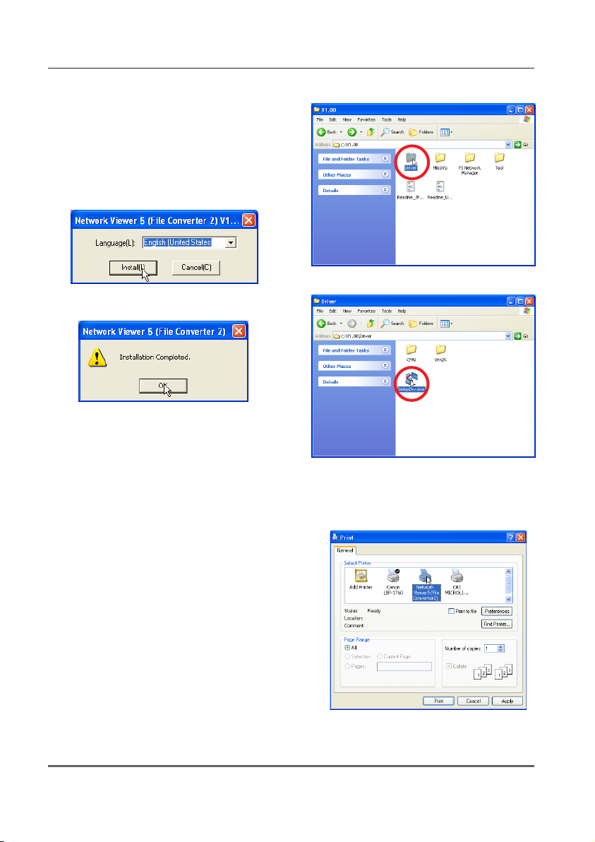
File Converter 2 installation
1 Set the supplied Network Viewer & Capture 5 CD-
ROM into the CD-ROM drive of your computer.
Double click SetupDrv.exe icon in the "Driver"
folder in the CD-ROM.
2 Select "English [United States]" from the pull-down
menu on the language selection window and then
click Install button to start installing.
Installed software and places
Network Viewer 5 (File Converter 2) is installed in the "Printers
and Faxes" folder in the "Control Panel".
● Network Viewer 5 (File Converter 2):
This is a kind of the printer driver to convert to the JPEG
data optimized to project by the projector from any of
the documents created by the application software.
* To uninstall Network Viewer 5 (File Converter 2), just delete the "Network Viewer 5(File Converter 2)" icon from the
"Printers and faxes" folder.
Page 21

21
3. Names and functions of the operation
screen
This chapter describes the functions of each part of the
operation screen.
Chapter
3
21
Page 22

22
Chapter 3 Names and functions of the operating screen
Network connection standby display
Turn on the projector and select either “Wired” or “Wireless” from the input menu of the projector.
The “Please wait...” message will be displayed on the screen. After short time, the network connection
standby display screen will appear as below. While the “Please wait...” message is shown, some
operations are invalid.
Network Connection Standby Display
Page 23
23
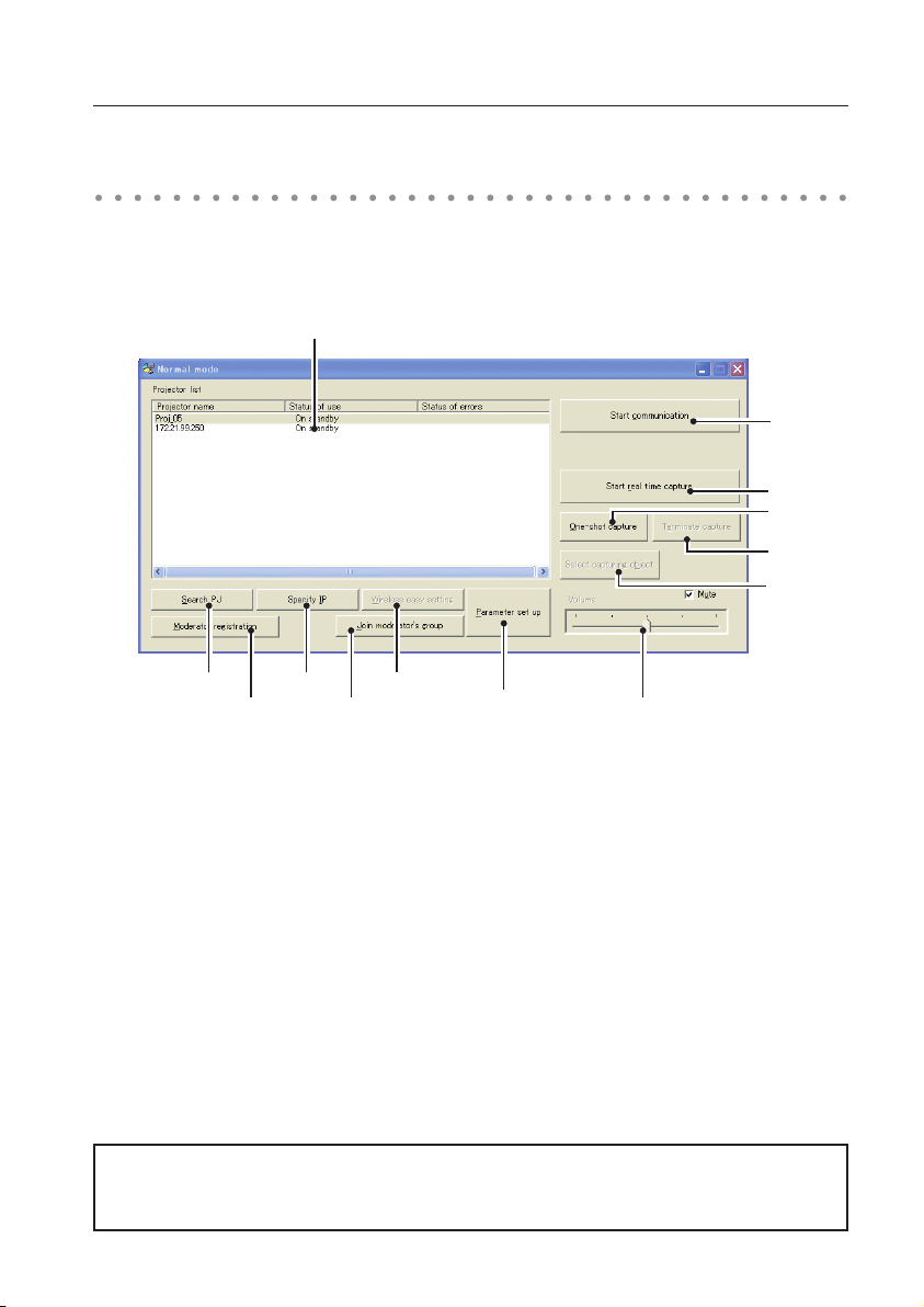
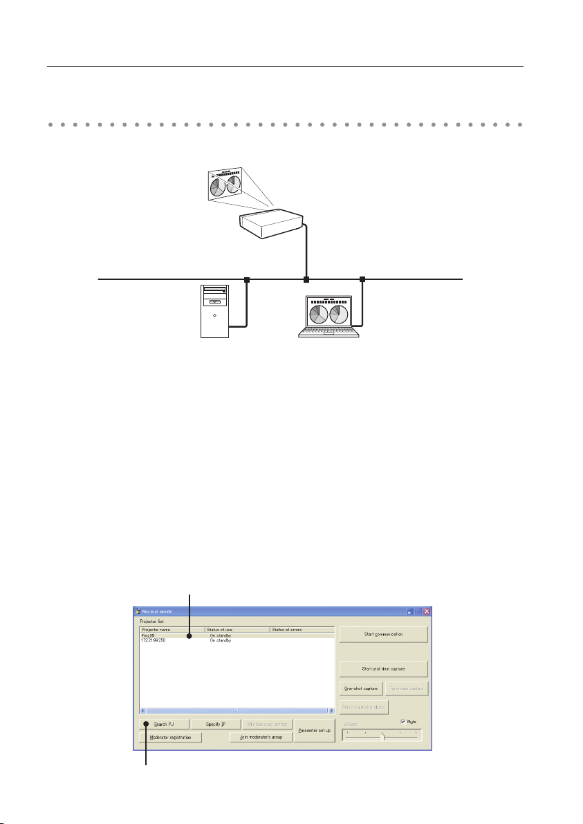
Network Capture 5 window
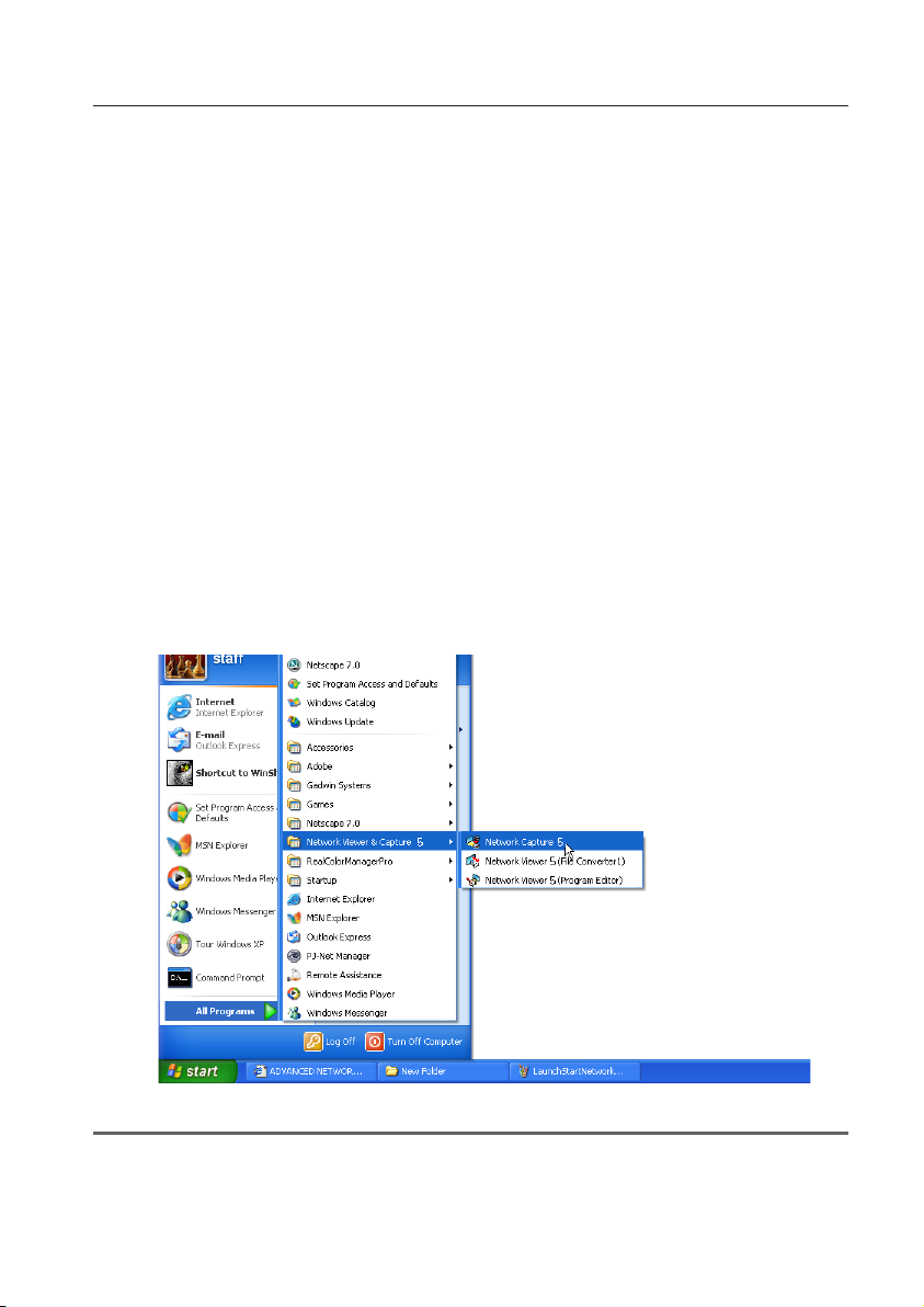
Network Capture 5 window
This software is to project the computer screen via the networks.
Select "All Programs" from the start menu --> Network Viewer & Capture 5" -->
"Network Capture 5", then following screen will appear. Then the program will start.
e
r
t
u
y
!2
q w
o
i
!0
!1
!3
Parts Names and Functions of the Screen
q Search PJ button
Search the projector connected to the networks.
w Specify IP button
When connected to a different segment network, the projector can not be retrieved automatically.
In that case, press this button, the "Search specified IP address list" window appears, and then
click Add button and enter the IP address directly to specify the projector in another window. The
registered multiple IP addresses can be searched at a time.
e Network Projector List
Display all the projectors connected to the networks.
Show unoccupied projector as “On standby” and occupied projector as “Real time capturing” or "In
One-shot mode". When registered in a moderator’s group, "On Moderator mode" will be shown.
The indication of the status of use with "#" indicates that your computer is now using the network
capture function.
After double-clicking on a projector name, the web browser gets activated and the projector setup
screen will be displayed.
Note on Windows Vista
When you use the Network Capture 5 software with Windows Vista, the warning dialog "User account
control" will appear. In that case, click Allow button to use it.
Page 24

24
Chapter 3 Names and functions of the operating screen
r Start communication button
Enter the Communication mode, and then , the capture edit window starts. The selected projector
shows the capture edit window.
t Start real time capture button
Capture (Project) the computer screen in real time. After the execution of "Start real time capture",
the application window disappears. • • • v
y Terminate capture button
Terminate the real time capture and the One-shot capture.
u One-shot capture button
Copy and capture (project) the computer screen without modification. After the execution of One-
shot capture, the application window disappears. • • • v
i Wireless easy setting button / Wireless easy release button
Configure the Wireless LAN setting just by clicking this button. ( The setting will be stored as AdHoc
system) For details, refer to "5. Wireless LAN configurations"-->"Easy wireless setting" (p.39). To
restore the easy setting, press the Wireless easy release button.
o Moderator registration button
Register a computer user as a moderator.
!0 Join moderator's group button
Join the moderator's group which is selected in the Network Projector list. It is not available if there
is no moderator registered.
!1 Parameter setup button
Activate the parameter setup window, and execute the connections setting, the image setting, and
the moderator's function setting. For detail, refer to "Parameter set up" (p.88).
!2 Select capturing object button
It is possible to designate the window to capture individually. This button is disabled by default,
so the full screen is captured. It is possible to change the capturing object function setting at
parameter settings. For detail, refer to "Parameter set up" (p.88).
!3 Volume adjust slider and Mute check box
Adjust the audio output from the real time capturing computer. The mute check box is checked by
default.
v To show the application window again, refer to the item "Commands on the task bar" (p.87).
Using the multiple network adaptors
When your computer provides multiple network adaptors, the network adaptor selecting window will
appear each time the Network Capture 5 software starts. Select a network adaptor and check the "Set
network adaptor as default" and then click OK. To change the setting, refer to the item "Parameter set
up" (p.88).
Page 25

25
4. Wired LAN configurations
This chapter describes the preparation for Wired
LAN setting with projectors and how to set the LAN
environment.
Chapter
4
25
Page 26
26
Chapter 4 Wired LAN configurations
Setting procedures and contents differ depending on the LAN installation location.
When installing, consult your system administrator to set up the LAN appropriately.
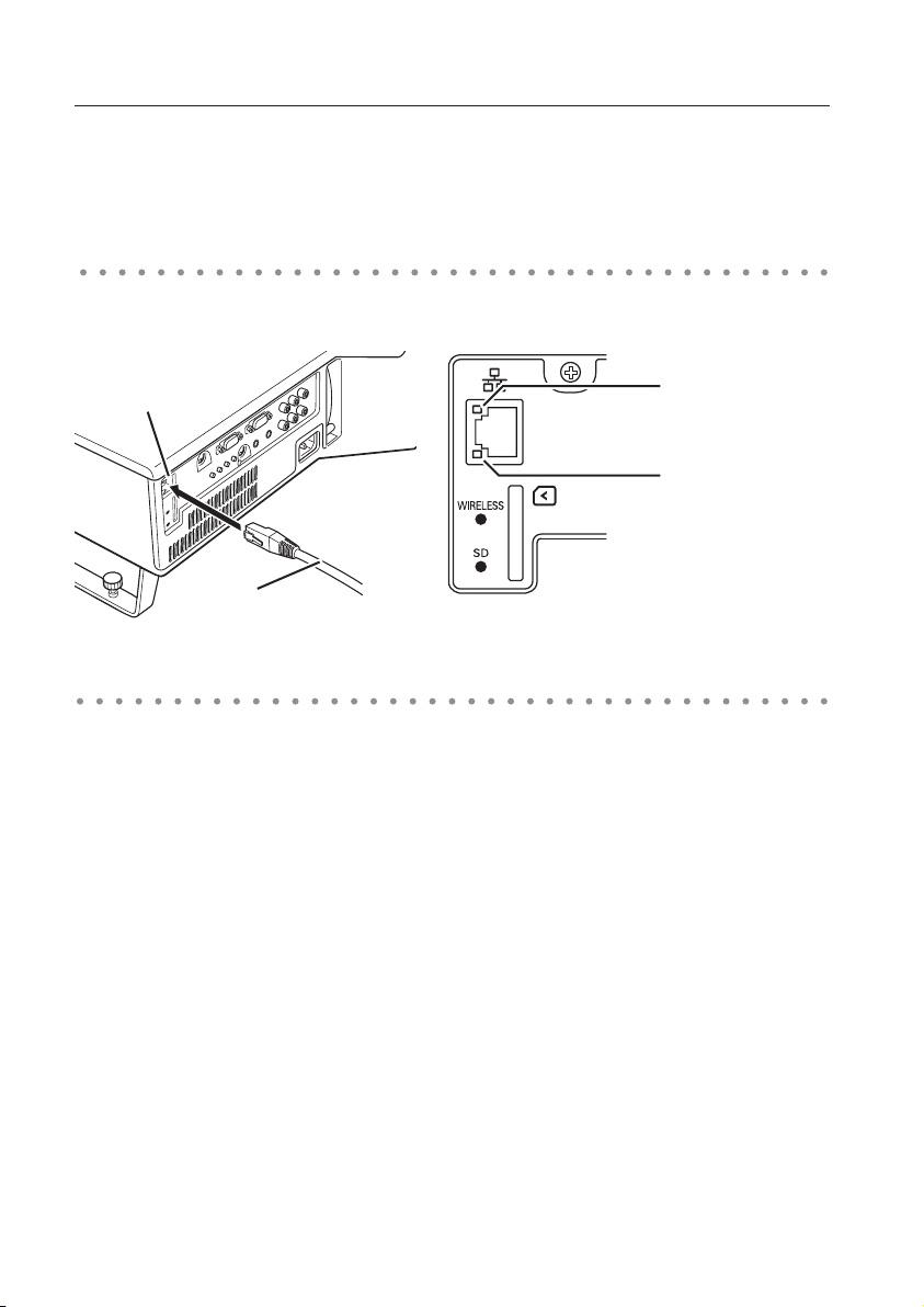
Connecting to the LAN line
Connect the LAN cable to the LAN connection terminal of the projector.
LAN Connection
Terminal
LAN Cable
* When the LAN setting is “Off ”, the two lamps
will not be on.
LINK/ACT Lamp (Orange)
Light or blink orange when
the projector is connected
to the network.
Speed Lamp (Green)
Light according to the
speed of the connected
network.
10 Base-T.........Off
100 Base-T ...... On
Network environment settings
Set the Wired LAN network through the projector menu.
Detailed network settings will be made with browser. Refer to “6. Basic setting and operation” (p43-62).
First, complete the settings described in this chapter before performing steps in “6. Basic setting and
operation.”
Setting Procedure
1. Turn on the projector and select “Wired” from the input menu of the projector.
The projector’s LINK/ACT Lamp will be on or blink. If the “Wired setting” is “Off”, it will not be on.
Follow step 2 and 3 to blink the lamp.
2. Select “Wired Setting” in the projector menu, and press SELECT button.
Select similar LAN environment among LAN1, 2 and 3 with the Point 7 8 buttons. (LAN1, 2, and
3 are the factory default setting environments. You can select three different environment among
setting LAN1–3. For each setting, refer to the chart on page 31.)
When selecting “Off” in the “Wired setting”, the LAN connection will be cut off. Use the function when
disconnecting the projector from the network.
3. Press the Point 7 8 buttons then the “Please wait...” message will appear and switching operation
will start. Switching will take a while and after completing the operation, the “Ready for use” message
will appear. During the switching period, the projector cannot be operated.
Page 27
27
Network environment setting
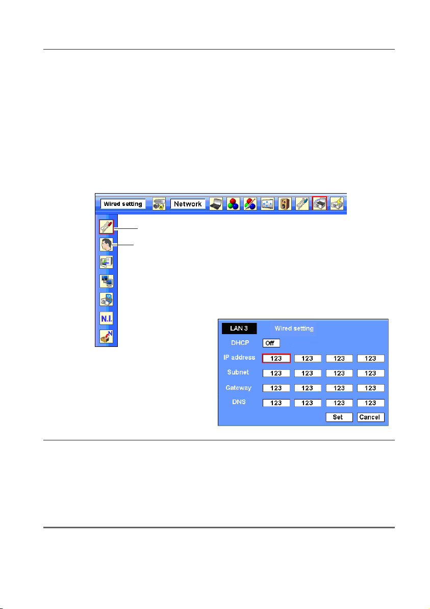
4. Press SELECT button.
LAN setting screen will appear and selected LAN settings will be displayed. Adjust each item to the
setting environment. Consult your system administrator about the detailed settings.
Adjust the figures with the Point ed buttons and move among the items with the Point 7 8
buttons.
5. After completing all the settings, select “Set” and press SELECT button. Now, all procedures have been
done. To cancel the adjusted settings, select "Cancel" and press SELECT button.
To confirm whether the settings are correct, follow the procedures described from the next page.
You can confirm the LAN settings you have made from “Network Information” (p.30). In such cases
that the LAN cannot be connected, see this screen.
Wired setting
Network PIN code
Wired LAN setting screen (Example)
Item Description
DHCP .......................... Sets DHCP function On or Off. When you setup the network setting manually, select "Off". When
IP address .................Sets IP address of the projector
Subnet .......................Sets Subnet mask. Normally sets 255.255.255.0
Gateway*2 .................Sets IP address of the default gateway (Router)
DNS*2.......................... Sets IP address of the DNS server.
*1 Set "On" only when the DHCP server is available on your network environment.
*2 Set [255.255.255.255] if the network does not provide the gateway (router).
*3 Set [255.255.255.255] if you do not use the function E-mail alert.
* While the network communication function (p.94) or moderator function (p.103) is to be executing, the menus
"Network capture", "Network viewer" and "Memory viewer" are displayed in gray.
it set On, IP address, Subnet, Gateway and DNS are automatically set according to your network
environment *
1
.
Page 28
28
Chapter 4 Wired LAN configurations
Confirming the operation
Confirm that the projector has connected to the LAN properly.
1. Activate “Network Capture 5” which is installed into the computer connected to the LAN .
2. After “Searching projector” message appears, the name of the projector* appears on the Network
Projector List, then the network setting has completed properly.
When the name of the projector does not appear and error screen appears, the network has
not connected yet. Try searching again with the Search PJ button. If error screen appears again,
reconfirm the LAN setting. When the projector is set in the location separated by the router, see next
page.
When Firewall function (Anti-virus software) is effective, network projector may not be found. In that
case, disable the Firewall function and try searching again.
✳ If the projector is named, the name will be displayed. The name can be set with the following
procedures in “6. Basic setting and operation” ➔ “Initial setting” (p48) . If the projector is not named,
IP address of the projector will be displayed.
Network Capture screen
Network Projector List
Search PJ button
Page 29
29
Confirming the operation
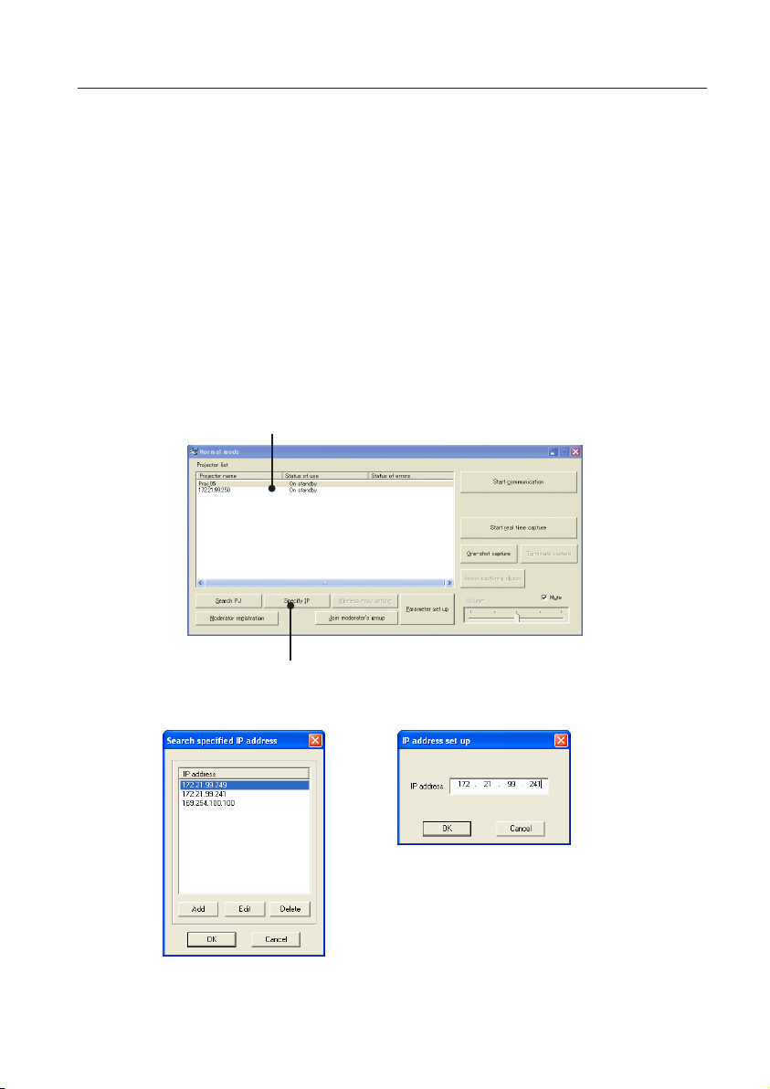
When set up the projector in the location separated by the router and the segment is different;
Projector will not be found nor displayed. In that case, the projector needs to be searched directly by
the IP address.
1. Press Specify IP button. "Search specified IP address" window appears.
2. Click Add button, "IP address set up" window appears. Enter the IP address of the projector and Click
OK button. Then, the projector will be added on the "Search specified IP address" window. Multiple
projectors are registered and they are stored even when the application is closed.
3. Click OK button on the "Search specified IP address" window, the registered multiple projectors
will be searched. Then, the projector will be added on the Network Projector List of the application
window.
Network Projector list
Specify IP button
"Search specified IP address" window
"IP address set up" window
Page 30
30
Chapter 4 Wired LAN configurations
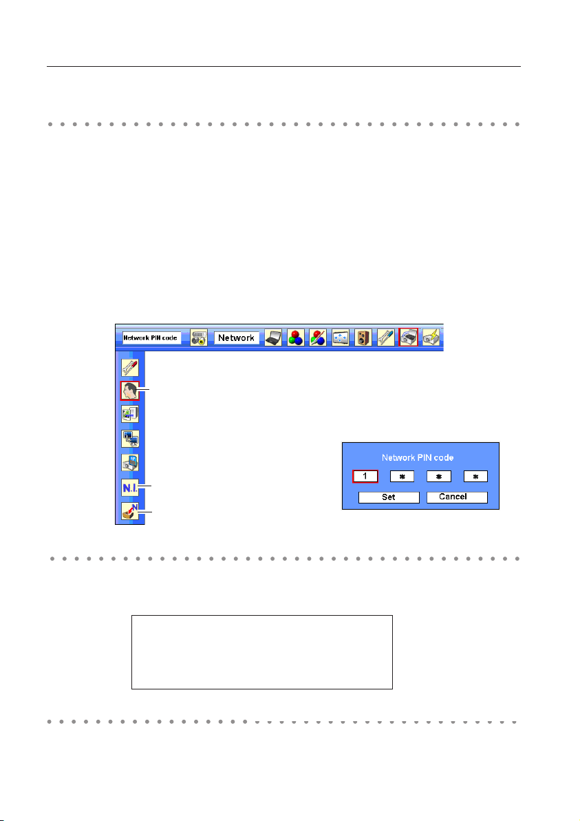
Network PIN code
The Network PIN code is to restrict the access from the networks to the projector.
After setting the Network PIN code, you need to enter it to operate the projector via the networks.
1. Select Network PIN code menu, and press SELECT button.
The Network PIN code screen will appear.
2. Set the Network PIN code.
Set the figures with the Point ed buttons and move to the next items with the Point 7 8 buttons.
Select “Set” and press SELECT button to set. To cancel the preset Network PIN code, select “Cancel”.
When you do not want to set the Network PIN code, set "0000".
It is recommended to set the Network PIN code if you use the projector via the networks. The Network
PIN code can be set also through the networks. See “6. Basic setting and operation” ➔ “Initial setting” ➔
“Network PIN code setting” (p49).
Network PIN code
Network PIN code screen
Network information
Wired factory default
Network information
Select Network information from the projector menu and press SELECT button to show LAN setting
environment of the currently selected projector. (The description below is an example and different
from what will be shown.)
MAIN PROGRAM: V1.000
MAC ADDRESS: 08007B650056
IP ADDRESS: 172.21.95.202
Wired factory default
Select “Wired factory default” from the projector menu and press SELECT button. All the wired LAN
settings will go back to the factory default settings. For details, refer to “Wired LAN factory default settings”
(p.31).
(See the menu above.)
Network information
(See the menu above.)
Page 31

31
Wired LAN factory default settings
Wired LAN factory default settings
SELECTED LAN
Parameter
LAN1 LAN2 LAN3
IP ADDRESS 169.254.100.100 192.168.100.100 192.168.100.100
SUBNET MASK 255.255.0.0 255.255.255.0 255.255.255.0
GATEWAY ADDRESS 255.255.255.255 255.255.255.255 255.255.255.255
DNS ADDRESS 255.255.255.255 255.255.255.255 255.255.255.255
IP CONFIGURATION MANUAL DHCP MANUAL
Page 32

32
Chapter 4 Wired LAN configurations
Page 33

33
5. Wireless LAN configurations
This chapter describes the preparation for Wireless
LAN setting with projectors and how to set the LAN
environment.
This projector contains the Wireless LAN module.
Chapter
5
The setting procedures and configurations differ
depending on the LAN installation location. Consult
your system administrator for installation and set the
LAN appropriately.
To operate via Wireless LAN, your computer has to
be equipped with a Wireless LAN card adapter which
supports IEEE 802.11b/g.
If connecting in Infrastructure mode with an access
point, the access point is required to support IEEE
802.11b/g.
Caution: Do not use a mobile phone or PHS near
(within 20cm/8inch) the projector. It may
cause malfunction.
33
Page 34

34
Chapter 5 Wireless LAN configurations
Setting the network environment
The projector contains the Wireless LAN adapter.
Set the Wireless LAN network through the projector menu.
Detailed network settings will be made with browser. Refer to “6. Basic setting and operation”. ➔"Network
configuration" (p.51). Complete the settings described in this chapter before performing the steps in “6.
Basic setting and operation.”
Setting procedures
With Easy wireless setting function, you can make Wireless LAN settings easily without any complicating
settings (p.39).
1. Turn on the projector and select “Wireless” from the input menu of the projector. The “Please wait...”
message will be displayed on the screen. After short time, the network connection standby display
screen will appear. Refer to “3. Names and Functions of the Operation Screen” (p.21).
2. Select “Wireless Setting” from the projector menu and press SELECT button.
Select similar environment between LAN 4 and LAN 5 with the Point 7 8 buttons. (LAN 4, LAN 5, and
SIMPLE* are factory default settings. Select similar environment to the installation location. For each
settings, refer to "Wireless LAN factory default settings" on page 42.)
✳ “SIMPLE” mode is used for simple setting without complicated LAN setting procedures to connect to
the Wireless LAN. See “Easy wireless setting” (p.39) for details.
3. Press the Point button then the “Please wait...” message will appear and switching operation will start.
Switching will take a while and after completing the operation the message will disappear. During
the switching period, the projector cannot be operated.
Wireless setting
Network PIN code
Network Information
Wireless factory default
Page 35

35
Setting the network environment
4. Press SELECT button. LAN setting screen will appear and the selected LAN settings will be displayed.
Adjust each item to the setting environment. Consult your system administrator for the detailed
settings.
Adjust the figures with the Point ed buttons and move among the items with the Point 7 8
buttons. When the network type is “AdHoc”, you do not have to change “Sub net” and “Gateway” and
leave them as default settings.
SSID/ESSID for the network type “Infrastructure” and “AdHoc” are required to be entered the same
characters into the projector, the access point, and the Wireless LAN compatible computer (up to 32
characters). Characters can be selected from A~Z, a~z, blank (space), 0–9, or - (hyphen) with the Point
ed buttons. Move to the next character with the Point 7 8 buttons.
You can confirm that the projector settings from “Network Information” in the projector menu (p.40).
5. After completing all the settings, select “Set” and press SELECT button. Now, all procedures have
been done. To cancel the adjusted settings, select the "Cancel" and press SELECT button.
To confirm whether the settings are correct, follow the procedures in “4. Wired LAN configurations”
➔ “Confirming the Operation” (p.28).
For configuring of WEP, WPA-PSK,
WPA2-PSK security, select “Next”. Refer
to “Configuring security with the
projector” on next page for details.
Item Description
DHCP .......................... Sets DHCP function On or Off. When you setup the network setting manually, select "Off". When
IP address .................Sets IP address of the projector
Subnet .......................Sets Subnet mask. Normally sets 255.255.255.0
Gateway*2 .................Sets IP address of the default gateway (Router)
DNS*2.......................... Sets IP address of the DNS server. Must be set when the E-mail function is used.
Network type .......... Sets Infrastructure or AdHoc mode. When the "AdHoc" is selected, the security "WPA-PSK" and
SSID/ESSID
*1 Set "On" only when the DHCP server is available on your network environment.
*2 Set [255.255.255.255] if the network does not provide the gateway (router).
*3 Set [255.255.255.255] if you do not use the function E-mail alert.
* While the network communication function (p.85) or moderator function (p.103) is to be executing, the menus
"Network capture", "Network viewer" and "Memory viewer" are displayed in gray.
its set On, IP address, Subnet, Gateway and DNS are automatically set according to your network
environment *
"WPA2-PSK" are not available.
...................Identifier of the wireless access point.
1
.
Page 36

36
Chapter 5 Wireless LAN configurations
Configuring security with the projector
Configure security with the projector by following the steps below.
After configuring the network in “5. Wireless LAN Configurations” (p.33-42), select “Next” in the LAN
setting screen and press SELECT button. The security configuration screen appears. Refer to “6. Basic
setting and operation” ➔ “Configuring wireless LAN setting and security setting” (p.53) as well.
WEP configuration screen
Use the Point ed buttons to select the security type. To disable the security, select “Disable.”
Use the Point 7 8 buttons to move among the items; use the Point ed buttons to adjust settings.
This projector provides the following security options. Use optimum security option on your network
environment.
WEP64(40)bit Open
WEP64(40)bit Share
WEP128(104)bit Open
WEP128(104)bit Share
WPA-PSK(TKIP)
WPA2-PSK(AES)
Notes when entering characters:
The “¥” symbol is displayed as “\” when the ASCII key is used. The “]” symbol is treated as a character
by the ASCII key, but it is not interpreted as a character by the HEX key. In HEX, the “]” symbol is
displayed in red and setting is denied.
You can not set all the characters with the “]” symbol. This will be considered as no operation.
ASCII key characters : Space - 0 to 9 A to Z a to z ! " # $ % & ' ( ) * + , . / : ; < = > ? @ [ ¥ ] ^ _ ` { | } ~
HEX key characters : 0 to 9 a to f
Page 37

37
Configuring security with the projector
Use of security type "WEP"
1. Use the Point ed buttons to select "WEP" security type.
2. Select “WEP Key index”. Use the Point ed buttons to choose the HEX or ASCII key. The four (#1–#4)
kinds of WEP keys can be configured. Use the Point 7 8 buttons to move to the right frame; use the
Point ed buttons to select a WEP key number (#1–#4).
Refer the table below for the usable number of characters at the WEP security option.
WEP option Characters
WEP64(40)bit ASCII
WEP64(40)bit HEX
WEP128(104)bit ASCII
WEP128(104)bit HEX
WEP configuration screen
5 characters
10 characters
13 characters
26 characters
3. Use the Point 7 8 buttons to select the Type field of the WEP key number that corresponds to the
one you selected above and press SELECT button. The WEP key entry screen appears. In the WEP key
entry field, all characters are displayed in “]”. Use the Point ed buttons to select a character; use the
Point 7 8 buttons to select a character position. Enter all the characters displayed with “]”.
When you select HEX at WEP key index and the entry key contains “]”, the “]” symbol is displayed in
red and setting is denied.
4. Use the Point 7 8 buttons to select “Set” and press SELECT button to return to the Wireless setting
screen. Select “Set” in the Wireless setting screen to complete the network setting.
Page 38

38
Chapter 5 Wireless LAN configurations
Use of security type "WPA-PSK", "WPA2-PSK"
1. Use the Point ed buttons to select "WPA-PSK" security type. WEP security setting fields are grayed
out.
WPA-PSK configuration screen
2. Select “Next” and press SELECT button. The PSK key confirmation screen appears.
3. Use the Point 7 8 buttons to select the key field and press SELECT button. The PSK key entry screen
appears. Enter the PSK key by using the Point buttons. If the input PSK key has an error, the PSK key is
indicated in red.
Available PSK key characters
ASCII code ......8 to 63 digits
Hex code .........64 digits
4. Use the Point 7 8 buttons to select “Set” and press SELECT button to return to the PSK confirmation
screen. Select “Set” and press SELECT button to complete the PSK key setting and the Wireless
setting screen appears. Select “Set” and press SELECT button to complete the network configuration.
* Security "WPA-PSK" and "WPA2-PSK" modes are not available when the "AdHoc" network type is selected.
* When you set the PSK keys with 64 digits, the projector checks whether all of the entered PSK keys are in Hex code or
not. If any of the ASCII code is included in the entered PSK keys, the entered PSK keys are indicated in red as error.
Page 39

39
Easy wireless setting
Easy wireless setting
With this setting, you do not need any complicated LAN setting procedures.
The network type will be AdHoc mode.
CAUTION: This function can be used only when logged in by Administrative right with
Windows XP and Windows Vista, and cannot be used with Windows 2000.
Windows XP should be Service Pack 1 or later version.
Setting Procedures
1. Turn on the projector and select “Wireless” from the input menu of the projector.
2. Select “Wireless Setting” from the projector menu and press SELECT button.
3. Select “SIMPLE” with the Point 7 8 buttons. Press the Point button then the “Please wait...” message
will appear and switching operation will start. Switching will take a while and after completing the
operation the message “Ready for use” will appear. During the switching period, the projector cannot
be operated. (“SIMPLE” LAN settings will be shown by pressing SELECT button. The settings cannot
be changed.)
4. Activate “Network Capture 5” which is installed in the computer.
5. Click Wireless easy setting button on the operation screen. The Wireless LAN setting screen will
appear and the computer will start to set up the Wireless LAN setting. (Adjust the computer’s
Wireless LAN environment to the “SIMPLE” setting LAN environment.)
After completing the settings, the computer will start searching the projector which was set as
“SIMPLE” and will display the name of the projector or the IP address on the projector list.
Confirm whether the LAN has been set correctly and works properly. Refer to “4. Wired LAN
configurations” ➔ “Confirming the operation” (p.28) for the confirmation procedures.
If the network setup is not succeeded, the error screen will appear.
Setting screen
Error Screen
Wireless easy setting button
Page 40

40
Chapter 5 Wireless LAN configurations
Computer environment and Wireless LAN connection;
Wireless LAN with Wireless Easy setting connection will be made via AdHoc mode. For setting contents,
refer to “Wireless LAN factory default settings” (p.42).
With the Easy setting, computer’s LAN environment setting will be switched to the setup environment.
Because of that, the LAN cannot work for the other operation while using “Network Capture 5”.
After terminating the application or pressing the Wireless Easy Setting button, the LAN environment
will automatically go back to the previous state.
Network PIN code
The Network PIN code is to restrict the access from the networks to the projector.
After setting the Network PIN code, you need to enter it to operate the projector via the networks.
Select “Network PIN code” from the projector menu and press SELECT button. Set with the same
procedures as setting Wired LAN Network PIN code. Refer to “4. Wired LAN Configurations” ➔ “Network
PIN code” (p.30).
Network information
Display the current LAN connecting environment. Select “Network Information” from the projector
menu and press SELECT button.
Wireless Information (Example)
Network information
MAIN PROGRAM: V1.000
MAC ADDRESS: 08007B650056
IP ADDRESS: 169.254.53.0
WIRELESS MODE: 802.11b
NETWORK TYPE: AdHoc
CHANNEL: 11
SSID/ESSID: WIRELESS
Wireless factory default
Select “Wireless factory default” from the projector menu (p.34) and press SELECT button. All the
wireless LAN settings will go back to the factory default settings. For details, refer to “Wireless LAN
factory default settings” (p.42).
Page 41

41
WIRELESS indicator display
WIRELESS indicator display
When the wireless LAN configuration is set up correctly and the wireless communication is established
with the access-point or the computer in the network, the WIRELESS indicator on the side panel lights
up. While the projector scans the equipment in the network, the WIRELESS indicator blinks.
WIRELESS indicator
Page 42

42
Chapter 5 Wireless LAN configurations
Wireless LAN factory default settings
Factory default settings for LAN4, LAN5, and SIMPLE as follows.
Selected LAN
Setting Items
LAN4 LAN5 SIMPLE
IP ADDRESS
SUBNETMASK
GATEWAY ADDRESS
DNS ADDRESS 255.255.255.255 255.255.255.255 255.255.255.255
IP CONFIGURATION MANUAL DHCP MANUAL
WIRELESS CHANNEL 11 11 11
NETWORK TYPE 802.11b AdHoc INFRASTRUCTURE 802.11b AdHoc
WIRELESS SSID/ESSID
(SSID/ESSID)
WEP
(WEP encryption)
WPA-PSK
(PSK key)
169.254.100.100 192.168.100.100 169.254. * . *
255.255.0.0 255.255.255.0 255.255.0.0
255.255.255.255 255.255.255.255 255.255.255.255
PJ-WIRELESS5 ANY PJ-WIRELESS5
DISABLE DISABLE DISABLE
DISABLE DISABLE DISABLE
WPA2-PSK
(PSK key)
DISABLE DISABLE DISABLE
Page 43

43
6. Basic setting and operation
Describes basic operation and settings below by using
the web browser.
• Initial setting
Setup the ba sic setti ng su ch as Pro jec tor na me,
Network PIN code, Time setting, etc.
• Network setting
Configure Wired/Wireless LAN environment.
• E-mail Setting
Configure E-mail function to manage the projector.
• SNMP Setting
Configure SNMP function to manage the projector.
Chapter
6
Caution: When operating the projector with the browser,
connect the projector to the computer with Wired or
Wireless LAN. Complete the connection in advance.
43
Page 44

44
Chapter 6 Basic setting and operation
Starting up the Browser
1. Turn on the projector.
2. Start up the Network Capture 5. The Network Capture 5 searches projectors in the network and lists
up the IP address or projector name of the projector on the Network Projector List.
3. Double click the projector to set from the Network Projector List.
4. The web browser will start up and display the setting page of the projector.
Select a display mode and login
This product provides 2 types of control mode, Standard Mode and Light Mode as below. Select
a proper mode to match your PC and network environment by clicking on the text link. Once you
select your desired display mode, the setting page you selected display mode will be displayed
automatically from the next login. To change the display mode, click "Top" on lower-right corner of
the setting page (p.45).
STANDARD MODE For computer display, displays graphical
menu s an d se tt in gs. Th is mo de i s
recommended for standard use.
LIGHT MODE Displays with 200 x 300 dots. This mode
is opti mized for use of the han dheld
computer, PDA, etc. It is also convenient
if the network traffic is heavy. (This mode
has some lim itat ions on the network
viewer and multi-control functions.)
If the password has been set on the setting page, the
authentication window will appear. In that case, type "user"
onto the User Name text area and the login Network PIN
code onto the Password text area and then click OK button.
* The entered User Name must be "user" and it can not be changed.
[Note]
When the projector is accessed for the first time or the Network
PIN code "0000" is set, the auto-login is performed and the next main
setting page is displayed.
Page 45

45
Starting up the browser
Display of main setting page
The following main setting page will be displayed depending on your display mode selection.
Perform various kinds of settings through this page. Click on the menus to display the control and
setting pages.
z Main setting page in the Standard Mode display
Clock display
Display on or off by
clicking text ON or OFF
Sub menu tab
S wi tc he s t h e su b
menu tab.
Page numbers
Switches the pages by
click ing the numbe r's
tab.
Main menu
For selection of control and
setting items of the projector.
Setting page
Displays the control and
setting items according to the
selected menu.
Returns to Display
Mode selection page
(+ p.44)
* To change the screen language, use the initial setting menu (p.48)
✐ This Standard mode display is mainly used through this manual for the setting and
control description.
✐ If your computer does not have the Adobe Flash
Player version 6 or later, follow the message on the
control page to install the Adobe Flash Player. For
further product information or installing, see the
Adobe homepage.
http://www.adobe.com
Page 46

46
Chapter 6 Basic setting and operation
x Main setting page in the Light Mode display
Sub menu tab
Page numbers
Main menu
Returns to th e display mode selec tion
page.
✐ The blank page appears if your PDA does not provid e a Adobe Flash
Player. You need to install the Adobe Flash Player. (+p.45)
Setting page
Returns to main menu
The network viewer function in the Light mode has following limitations;
- Cannot select the program or folder for the display.
- Cannot check up the images in the folder or program.
How to use the setting page
To control and set up the projector, use the setting menus on the web browser. The basic operation and
procedures commonly used on this manual are described below.
Example of the Setting Page
The setting pallet appears after clicking the item. Change the
value by clicking s or t button, or type the number onto the
text box directly and then click Set button.
* Each item has a valid setting range respectively.
Setting Pallet
✐ The value in the text box indicates current value.
✐ Each item has a valid setting range. The setting value exceeding its range becomes invalid. Some control items can
not be used depending on the selected input mode or functions of the projector you use. In that case, the values of
those items are indicated with "---".
Page 47

47
Type of the setting pallet
Text box setting
Enter the number or text and then
click Set button.
or
Change a value with s or t
button and then click Set button.
The valu e ch anges quic kly when
s or t button is kept pressing.
Pull-down menu setting
Select an item with pull-down
menu button and then click Set
button.
or
Select an item by clicking s or t
button.
How to use the setting page
Radio button setting
Select an item by selecting a radio
button
Check box setting
Sel ect items by tick ing on c heck
boxes.
Page 48

48
Chapter 6 Basic setting and operation
Initial setting
After installing the projector, perform the following basic initial setting.
Click Initial Setting on the main menu to display the initial setting page.
Item Description
Language ................. Switches display language on the setting page. English or
Model name ............ Indicates the model name of the projector.
Projector name ....... Sets the name of projector. This projector name is listed on
Network PIN code ...........
PJLink ......................... Switches PJLink password authentication on or off.
Password................... Password for PJLink function
Japanese.
the application window of the Network Capture software.
Sets the Network PIN code to login the setting page (+p.30,
p.40)
Page 49

49
Initial setting
Network PIN code setting
This is to set the Network PIN code to res trict the access from an
unauthorized person through the network.
Enter a 4-digit number as the Network PIN code onto the text box and
click Set button.
The projector's network part begins restarting and it takes about 20
seconds. Close (Quit) the web browser and access to the login page
again in 20 seconds. This is to perform the login authentication firmly.
The default Network PIN code as [0000], which means no Network PIN code is set.
✐ When you connect the projector to the network, it is recommended to set a new Network PIN code. Only a four-
digit number is valid for the Network PIN code.
✐ If you forget the Network PIN code to the projector, you can check it by selecting "Network PIN code" sub menu
from "Network" menu on the projector. For fur ther information, please see item "Network PIN code setting"
(+p.30, p.40).
PJLink and password setting
This is to set the PJLink password authentication on or off. If "On" is set
with the PJLink pull-down menu, the password must be required. Enter
a password* onto the text box and click Set button.
Refer to the projector owner's manual for further details of the PJLink
function.
✐ 1 to 32 alphanumeric characters can be used for the password.
What's PJLink?
The projectors equipped with PJLink function can be used together on the same network, regardless
of model or brand, for centralized control and monitoring. This standard was established by the Japan
Business Machine and Information System Industries Association (JBMIA). http://pjlink.jbmia.or.jp/
Page 50

50
Chapter 6 Basic setting and operation
Item Description
NTP address ............. Enter the address of NTP server. Please consult your
Temperature ............ Switches display temperature unit Centigrade or
Time setting ............. When clicking
Current time ............ Indicates current date and time set on the projector
Date ............................Sets date in manual
Time ............................Sets time in manual
network administrator for setting up of the NTP server.
Fahrenheit
AUTO button, the date and time set on
your computer are set to the projector. The timer icon
appears when time is set up correctly.
Date and time setting
NTP is abbreviated expressions of Network Time Protocol. It is a protocol to acquire the exact current
time via the network. This projector acquires the current time from the NTP server and update the time
in the network module. After setting the NTP address, the projector acquires the time per 24 hours. If
the projector fails acquiring the time from the NTP server, the projector tries to acquire the time every 1
hour until it succeeds.
When the NTP address is not set, perform the time setting with "Auto-setting" or "manual setting"
described below.
Auto setting
Click AUTO button on the page, the date and time set on your computer are set to the projector.
Note:
Confirm that your computer has a correct clock time before performing the auto time setting.
Manual setting
Click the item Date or Time and enter the date or time on the input box
with adequate format.
Date is in year/month/day format.
ex. 2007/10/05
Time is in 24-hour:minute format.
ex. 18:30
This projector does not provide the built-in battery. The date and time information are lost when
the projector turns off ( when "Eco" is set for the stand-by mode (Refer to p.72)), or the network
configuration is reset, or the input mode "Wired" or "Wireless" is turned. The timer function is disable
until time is set up correctly. When using the NTP address for time setting, the current time is acquired
at the projector starting up and the timer function is activated after finishing the time setting
correctly.
Page 51

51
Network configuration
Click Network on the main menu. The following setting page is displayed. Set up the
projector's network environment on this Setting sub menu.
Setting of LAN
1. Select a type of LAN from Change setting pull down menu.
LAN1(Wired)
LAN2(Wired)
LAN3(Wired)
LAN4(Wireless)
LAN5(Wireless)
Simple(Wireless)
For the default setting of the above LAN, see the items "Factory Default Setting".
Network configuration
Item Description
Change setting .......Selects LAN1 to LAN5 and Simple
IP configuration......Sets DHCP or Manual
IP address .................Sets IP address of the projector
Subnet mask............Sets Subnet mask.
Default gateway*
DNS*2.......................... Sets IP address of the DNS server.
*1 Set [255.255.255.255] if the network does not provide the gateway (router).
*2 Set [255.255.255.255] if you do not use the function E-mail alert.
1
...........Sets IP address of the default gateway (Router)
Page 52

52
Chapter 6 Basic setting and operation
2. Select either "Manual" or "DHCP" from IP configuration pull
down menu. When "DHCP" is selected, IP address, Subnet
mask, Default Gateway, DNS are automatically configured by
DHCP function. Only the DNS address allows you to set up
manually if the DNS address information is not provided on
your DHCP server. When selecting "Manual", configure all the
items manually. For further information, contact your network
administrator. The address must be entered as 4 number
groups separated by a dot like [192.168.001.101].
3. Af te r comple ti ng th e networ k co nf ig ur at ion , pr es s
Regist button to register the network informatio n. The
Simple(Wireless) setting is fixed, which cannot be changed
from factory default value.
4. To apply the setting, press Set button. The network of the projector starts re-booting and applies the
setting. It takes about 20 seconds to complete. Close the web browser and access to the login page
again in 20 seconds.
On the screen of the projector, the “Please wait...” message will appear and switching operation will
start. Switching will take a while and after completing the operation, the “Ready for use” message will
appear. During the switching period, the projector cannot be operated.
When you use LAN4(wireless) or LAN5(Wireless), the setting items of page [2] and [3] are activated
and you can setup Wireless LAN setting and Security setting. See the item " Configuring Wireless LAN
Setting and Security Setting" for further setting.
Page 53

53
Configuring wireless LAN setting and security setting
Configuring wireless LAN setting and security setting
Configure the wireless LAN setting and security setting for LAN4 and LAN5.
Configuring wireless LAN setting
1. Click page [2] of setting pages. Following wireless LAN setting can be done. After completing the
configuration, press Set button.
Item Description
Wireless Mode ........Select the Communication standard 802.11b or 802.11b/g
Network Type. ......... Select either “Infrastructure” or “AdHoc”. When selecting the "AdHoc", the security
"WPA-PSK" and "WPA2-PSK" mode are not available.
SSID/ESSID ...............Set the SSID/ESSID. (up to ASCII 32 characters)
SSID/ESSID is case-sensitive. Even though all characters on the Wireless
information is uppercase, it is necessary to distinguish between upper case and
lower case characters.
Channel .....................I f you use the projector in 802.11AdHoc mode, select the channel, from 1 to 11.
Page 54

54
Chapter 6 Basic setting and operation
Configuring wireless LAN security setting
Click page [3] of setting pages. Following wireless LAN security
setting can be done. After completing the configuration, press
Set button.
Item Description
Network security ...Sets the type of encryption. Following types are available.
WEP64(40)bit Open
WEP64(40)bit Share
WEP128(104)bit Open
WEP128(104)bit Share
WPA-PSK(TKIP)
WPA2-PSK(AES)
Input type.................ASCII or HEX. See item "Notes for entering characters"
Key index1 - 4..........Enter keys of encryption.
The used number of character changes as the table below according to the type
PSK ..............................Available when the "WPA-PSK(TKIP)" or "WPA2-PSK(AES)" is selected.
The PSK key must be no fewer than 8, nor more than 63 digits with ASCII code,
of WEP encryption and input type.
WEP option Characters
WEP64(40)bit ASCII
WEP64(40)bit HEX
WEP128(104)bit ASCII
WEP128(104)bit HEX
5 characters
10 characters
13 characters
26 characters
Four key indexes can be set, however, the only one with check on its radio
button is effective. Both of the number and value of the key index in effect must
be same as those of your computer and the access point.
Depending on computers and access points, you may be allowed to select only
one WEP key. In that case, use key index1.
and 64 digits with Hex code.
Notes for entering characters:
The “¥” symbol is displayed as “\” when the ASCII key is used. The “]” symbol is treated as a character
by the ASCII key, but it is not interpreted as a character by the HEX key. In HEX, the “]” symbol is
displayed in red and setting is denied.
You can not set all the characters with the “]” symbol. It will be considered as no operation.
ASCII key characters : Space - 0 to 9 A to Z a to z ! " # $ % & ' ( ) * + , . / : ; < = > ? @ [ ¥ ] ^ _ ` { | } ~
HEX key characters : 0 to 9 a to f
Page 55

55
E-mail setting
E-mail setting
This product has an E-mail function which can send an alert message to users or an
administrator if it detects an abnormality on the projector or run out of the life span
of the lamp. Click E-mail Setting on the main menu and follow the below steps.
Item Description
1
..........
SMTP server*
Administrator
address ......................Sets E-mail address of administrator
Add e-mail
address ...................... Sets E-mail address of the user to send a mail when the
Sets server name or IP address of the SMTP server
projector has an abnormality.
1 Setting SMTP server and administrator address
Set the server name or IP address of the SMTP server*1 and administrator address. The administrator
address is set to "Reply-To" address of the message sent from the projector.
*1 The SMTP server is a server for sending E-mail. Please contact your network administrator to have this SMTP
server address. When the server name for SMTP server is used, DNS must be set up to activate the E-mail
(+p.51)
function.
✐ If the projector sends an alert message due to the abnormality on the projector but the SMTP server is down in
some other reason, the message will not be sent. In that case, the message "Unable to connect to server." will be
displayed on the setting page. To clear this message, set up SMTP server address again.
✐ To use the E-mail function, it must be set the DNS address on the Network setting page correctly.
✐ You cannot use this E-mail function if the DNS server and SMTP server cannot be used in your network environment.
✐ The projector does not send message to the address set in "Administrator address" text box. If you want to send
e-mails to the administrator address, enter the administrator address into "Add e-mail address" text box.
Page 56

56
Chapter 6 Basic setting and operation
2 Registering and deleting E-mail addresses
Click "Add E-mail address" and type the E-mail address onto the
text box and click Set button. To check the registered addresses,
click Check/Delete sub menu tab. The addresses are listed as the
figure on the right.
✐ Up to 10 E-mail addresses can be registered.
To delete the registered addresses, check the address you want to
delete and click Delete button.
3 Option selection for sending alert mail
Click Option sub menu tab. Check the condition items under
which alert mail will be sent and click Set button.
Please refer to the item "Examples :Type and contents of alert
mail" described on the next page.
[1]––––––––––––––––––––––––––––––––––
o
When PJ lamp is off.
o When PJ lamp replacement time is reached.
o When internal PJ power circuit is failed.
o When internal PJ temperature is too high.
o When PJ is turned into Standby in proper user
operation.
[2]––––––––––––––––––––––––––––––––––
o
When accumulated filter use time reaches
[ ] hours.
o When Power management function turns PJ
lamp off.
o When the signal is interrupted.
o When Auto Play is failed.
[3]––––––––––––––––––––––––––––––––––
o
When lamp Corres. Value reaches
[ ] hours.
Attached message
Check / Delete
Option
✐ "When PJ lamp is off" signifies the lamp goes out
without user operation. "When PJ is turned into
Standby in proper user operation" signifies that the
projector is turned on by using the web browser
and then it is turned into standby with ON/STANDBY
button on the top control or the remote control.
✐ If condition "When Auto Play is failed" is checked, the
trap is sent when the error occurs during the auto
display operation using with the network viewer
function (+ p.109). For further information of the
error, refer to item "Auto Display setting and control
page [3]"(+p.124).
✐ The length of mess age sho uld be l ess tha n 25 5
characters.
✐ Up to 99,999 hours can be set for use time.
Page 57

57
E-mail setting
Examples: Type and contents of alert mail
When the projector has an abnormality, the following alert messages are sent to the registered E-mail
address depending on your selected condition. Administrator or user can take an efficient action
quickly by receiving this message. This is very useful to maintain and service the projector.
The following are examples of received messages.
● When internal PJ temperature is too high:
TITLE: Message from projector
10-03-2007 00:59
Projector Model Name: model name
TCP/IP: 192.168.1.201 Projector Name: Proj05
It sends you following message.
* The Projector lamp is turned off, because internal Projector temperature is too high.
Wait for the completion of the cooling process and make sure the projector has been
turned into Standby. Then turn the projector on again.
If the Indicator continues flashing, check the air filter for dust accumulation.
[A] 81.5 degrees fahrenheit [B] 134 degrees fahrenheit [C] 95.6 degrees fahrenheit
Temperature of Sensor B is too high.
✐ The projector let users know the information which thermal sensors inside the projector detected the
abnormal temperature risen and so the projector was turned off. Please refer to item "Power control
and status check" (+ p.64) for the location of the sensors and each temperature . Also see the owner's
manual of the projector for further details.
● When internal PJ power circuit is failed:
TITLE: Message from projector
10-03-2007 00:59
Projector Model Name: model name
TCP/IP: 192.168.1.201 Projector Name: Proj05
It sends you following message.
*The Projector lamp is turned off, because Projector power circuit is failed.
Unplug the Projector from AC outlet and ask servicing to qualified service personnel.
MAIN, P-FAIL OK
MAIN, 1.8V OK
MCI, P-FAIL NG
✐ The projector lamp was turned off, because the projector power circuit failed.
Unplug the projector from AC outlet and contact a qualified service personnel for service with the error
information.
Error information
Page 58

58
Chapter 6 Basic setting and operation
● When PJ lamp replacement time is reached:
TITLE: Message from projector
10-03-2007 00:59
Projector Model Name: model name
TCP/IP: 192.168.1.201 Projector Name: Proj05
It sends you following message.
*The PJ lamp replace time is reached.
✐ Replace it with a new lamp immediately and reset the lamp counter. If the projector is used without
resetting the lamp counter, the alert mail is se nt to users in ever y powe r-on of the p rojector. Thi s
alert mail will not be sent when the mail sending condition "When the life span of lamp is reached" is
unchecked.
● When lamp corres. value reaches preselect use time:
TITLE: Message from projector
10-03-2007 00:59
Projector Model Name: model name
TCP/IP: 192.168.1.201 Projector Name: Proj05
It sends you following message.
*The accumulated lamp use time reaches 1800 hours.
Prepare for the lamp replacement.
Discretional messages
✐ The projector sends a free message when the lamp use time (Corresponding value) reaches the
preselected lamp use time. It can be used for preparation of the lamp replacement and the maintenance
required.
Page 59

59
SNMP setting
SNMP setting
This product provides a SNMP (Simple Network Management Protocol) agent
function. The SNMP consists of a manager and agents. The group which exchanges
information with SNMP is called "Community". There are two access modes in a
community, Refer (read only) and Set (read- write). This product allows to use Refer (read only) only. The
SNMP message informs the projector status called "Trap" to an administrator. Click SNMP Setting on
the main menu and set up each item.
PJ information
Item Description
Contact ..................... Enter user name of the projector etc. (optional)
Place...........................Enter place of the projector (optional)
Community
name(refer) ............. Enter community name (read only). Default name is
"public".
✐ The SNMP agent provided with this product is based upon MIB-2 defined by RFC1213. For private MIB
information, refer to file "Mibinfo/XUPjNet.mib" in the CD-ROM.
Page 60

60
Chapter 6 Basic setting and operation
Trap
Item Description
Community name ........... Enter community name to send "Trap". Default name is
"public".
Trap address ............ Enter IP address of the SNMP manager computer to
receive "Trap". Up to 10 address can be registered.
✐ Up to 10 trap addresses can be registered.
Trap check/delete
Check and delete the trap address
Checking the registered trap address and deleting the address.
To delete the address, tick the check box in front of the IP address
and click Delete button.
Page 61

61
Trap option
Trap option setting
Tick the check boxes in front of the condition item to send the trap.
✐ Click Set button if you tick or un-tick the check box on a page.
[1]––––––––––––––––––––––––––––––––––
o
When PJ lamp is off.
o When PJ lamp replacement time is reached.
o When internal PJ power circuit is failed.
o When internal PJ temperature is too high.
[2]––––––––––––––––––––––––––––––––––
o When PJ is turned into Standby in proper user
operation.
o When accumulated filter use time
reaches [ ] hours.
o When Power management func tion turns PJ
lamp off.
SNMP setting
[3]––––––––––––––––––––––––––––––––––
o
When the signal is interrupted.
o When Auto Play is failed.
o When lamp Corres. Value
reaches [ ] hours.
✐ "When PJ lamp is off" signifies the lamp goes out without user operation. "When PJ is turned into Standby in proper user
operation" signifies that the projector is turned on by using the web browser and then it is turned into standby with ON/
STANDBY button on the top control or the remote control.
✐ Up to 99,999 hours can be set for the time setting.
✐ If condition "When Auto Play is failed" is checked, the trap is sent when the error occurs during the auto display
operation using with the network viewer function (+p.109). For further information of the error, refer to item "Auto
Display setting and control page [3]"((+p.123).
Page 62

62
Chapter 6 Basic setting and operation
Page 63

63
7. Controlling the projector
Describes controlling and setting of the projector by
using the web browser.
Chapter
7
63
Page 64

64
Chapter 7 Controlling the projector
Power control and status check
Click Power & Status on the main menu. The control page will be displayed.
By clicking ON or Standby button on the page, the power of the projector can be
controlled.
Confirmation window as
shown in the below appears
when the Standby button is
pressed.
Item Description
Popup confirmation window
PJ status
Power ............................ Displays the status of the lamp. (ON, OFF, On starting up, On cooling down)
Status ............................ Displays the status of the projector's power. (Refer to next page.)
Power control .............. Controls the projector power by clicking the "ON" or "Standby" button.
PJ temp.
Inside temp.A ............. Displays the surrounding temperature of lamp in the projector.
Inside temp.B .............Displays the surrounding temperature of panel in the projector.
External temp. ............Displays the surrounding temperature of the intake vent.
.......... The warning icon will appear if the temperature exceeds a specified value. Check if there
* The temperature unit can be set either Centigrade or Fahrenheit in the item "Initial
✐ The projector cannot be turned on while the projector is cooling down.
✐ The web browser checks and updates the projector's condition every 30 seconds automatically.
is no object to obstruct the airflow around the intake or exhaust vent. It might be airfilter
clogged. Clean up the airfilter.
Setting". (+p.50)
Page 65

65
Power control and status check
About projector condition
Status Description
Normal ..................................................................Projector is operating normally.
Power management in operation
Lamp failure........................................................Lamp failure is occurring
Abnormal Temperature ..................................The temperature of the projector became too high
Cooling down after abnormal Temp.
Standby after Abnormal Temp. ................... Projector detects abnormal temp. and is set into standby mode.
Power failure ..................................................... Power failure has occurred inside the projector. Projector is turned off.
If the power failure occurs on the projector, "Power failure" is indicated on
......................Power management is operating
Projector detects abnormal temp. and is cooling down itself.
Unplug the AC cord and contact a qualified service personnel for service.
the status column and the information icon appears on the power column
as shown below. Click this icon to display further information of the power
failure.
Click this icon to disp lay
further information of the
power failure.
When a security (PIN code lock) has been set on the projector, you also cannot control it through
the network. To control the projector through the network, unlock the security on the projector
using with the projector's menu control.
Caution about turning on/off the projector via the networks
When turning on/off the projector via the networks, preset the projector as follows:
1. Select “Setting” from the Projector menu.
2. Select “Standby mode” from the Setting menu and set it as “Normal”.
If you set this function as Normal, the network part of the projector is constantly provided with
power even if the projector is turned off. If you set this as Eco, then the network part will be turned
off when you turn off the projector. Consequently, you cannot turn on/off the projector via the
networks.
Page 66

66
Chapter 7 Controlling the projector
Controls
Click Control on the main menu. The setting method differs depending on the
contents of the page. Click on the page number to change pages and select desired
setting items.
✐ Please see the owner's manual of the projector to have the further informa-
tion of each control item.
Input
This function is to select the input mode and source mode of the projector. Click Set button after
selecting the input and source mode.
Item Description
Input ........................... Selects input mode of the projector.
Source ........................ Selects signal source of the input.
Computer1 : RGB
RGB(Scart)
Computer2 : RGB
Video : Auto
Video
S-video
Component
Network: Wired
Wireless
✐ The control page displays valid control items depending on the selected input mode, signal or functions of the
projector you use, therefore, there may be different controls between the described items and actual control items
on the page display. For further information , refer to the projector's owner's manual.
When the projector is standby, only the timer on the setting menu is available; others are not available.
✐
Page 67

67
Controls
System
This function is to select the system of signal input to the projector. The available system mode are
listed on the pull-down menu button according to the input signal. Select a system and then click Set
button.
Available selection at the RGB input
Item Description
XGA1 .......................... It automatically switches to the proper computer
* The computer system modes (VGA, SVGA, XGA. SXGA,
Available selection at the Video/S-video/Scart input
Item Description
AUTO .......................... It automatically switches to the proper color system of
* The selectable color systems are PAL, SECAM, NTSC,
* AUTO is fixed at the Scart input.
Available selection at the Component input
Item Description
AUTO .......................... It automatically switches to the proper scanning system
* The selectable scanning systems are 480i, 575i, 480p,
system of the input signal.
UXGA, WXGA...) which meet the input signal listed.
the input signal.
NTSC4.43, PAL-M and PAL-N.
of the input signal.
575p, 720p, 1035i and 1080i.
✐ If the modes (Mode1 to Mode5) stored in the item "PC Adjustment" (+ p.70) are available, they are also listed
together with the above mode.
Page 68

68
Chapter 7 Controlling the projector
Image adjustment
This function is to adjust the projected picture image and save the image mode. To store the adjusted
value, click Store button, and to load the adjusted value, click Load button.
Item Description
Contrast.....................Adjusts picture contrast
Brightness ................Adjusts picture brightness
Color ...........................Adjusts picture color saturation
Tint ..............................Adjusts picture hue
Item Description
Color temp. ..............
White balance
Red, Green,
Blue ...................... Adjusts each white balance respectively.
Sharpness .................Adjusts picture sharpness.
* When the value of the white balance is changed, the color temp. indicates
Item Description
Gamma ........................
Noise reduction
Progressive
Reset ...........................Resets the Image adjustment to previous levels.
Store ........................... Stores the Image adjustment values. Select an item
Load ............................ Loads the Image mode.
Input source
Image mode Video Computer
Dynamic 4 4
Standard 4 4
Real * 4
Cinema 4 *
Blackboard(Green) 4 4
Colorboard 4 4
Image 1 - 4 4 4
"Adj."
✐ The mark "4" indicates the available image mode in the selected input
source. The error message appears when the disabled image mode
indicated with "*" is selected.
Sets a color temperature mode.
Adjusts brightness of darker part of the picture.
....... Switches noise reduction mode
.................. Switches progressive mode
[Image 1 - Image 4] from the pull-down menu and click
Store button.
Select an image mode from
the pull-down menu and
click Load button. There
may not be available mode
depending on the input
mode as shown in the table
left.
Page 69

69
Controls
Sound
This function is to adjust the sound of the projector. The values in the text box represent the current
control value or status.
Item Description
Volume ...................... Adjusts the sound volume from the speakers.
Mute ........................... Suppresses the sound.
Page 70

70
Chapter 7 Controlling the projector
PC adjustment
Click PC Adj. on the main menu. This function is to adjust the signal from the
computer connected to the projector to obtain the proper picture image on the
screen.
Item Description
Current mode ...........
Auto PC adj. ............. Performs automatic adjustment.
Fine sync. .................. Performs Fine Sync adjustment.
Total dots .................. Adjust the number of total dots in the horizontal period.
Clamp.........................Adjusts the phase of the clamp.
Display area
Horizontal ...............Adjusts the image area horizontally.
Vertical .................Adjusts the image area vertically.
Displays a current mode like VGA, SVGA, XGA, SXGA, UXGA,
WXGA, etc. or MODE1 - MODE5 are the customized mode
created by using the "Mode Store" function described below.
Item Description
Position
Horizontal ........... Adjusts the horizontal position of the screen.
Vertical .................Adjusts the vertical position of the screen.
Reset ........................... Resets the PC adjustments to the previous levels.
Mode Store .............. Stores the PC adjustment values. Select a mode no.
[Mode1 - Mode5] from the pull-down menu.
Mode Free ................ Clear the PC adjustment values. Select a mode no.
[Mode1 - Mode5] from the pull-down menu.
Page 71

71
Setting up the projector
Setting up the projector
Click Setting on the main menu. This function is to set up the projector. Select the
sub menu [Screen setting], [Setting 1] or , [Setting 2] and then set up each setting.
Item Description
Screen ........................ Switches the screen mode. There may not be available
mode depending on the input mode as shown in the
table below.
Input source
Screen mode Video Computer
Normal 4 4
True * 4
Wide 4 4
Full * 4
Digital zoom+ 4 4
Digital zoom– 4 4
✐ The mark "4" indicates the available screen mode in the selected input
source system. The error message appears when the disabled screen mode
indicated with "*" is selected.
Page 72

72
Chapter 7 Controlling the projector
Item Description
Language ................. Sets the language display of projector's on-screen
Auto setup ............... Executes the Auto PC Adj, and Input Search function
Auto PC Adj. .......Sets Auto PC Adjustment mode.
Input Search .......Sets the auto-input signal detection mode.
Blue back .................. Sets the blue screen background when no signal input.
Display ....................... Switches on or off the on-screen menu display on the
Countdown off .... Displays image during the starting up.
Item Description
Logo ........................... Sets the logo display on the screen during the startup.
Ceiling ........................ Sets the image top/bottom and left/right reversed.
Rear ............................. Sets the image left/right reversed.
Standby mode ........ Sets the network function enable or disable in the
Normal ..... Enable
Eco ............Disable
No show .................... Sets the black out image temporarily.
display menu.
below according to the each setting after clicking
button.
screen.
standby mode.
Start
Item Description
Freeze......................... Sets the image to freeze mode.
Power
management .......... Sets into the selected power management mode if the
* The specified time can be set 1 to 30 min.
On start ..................... Sets the power-on mode when the AC cord is
Lamp control ........... Selects lamp control mode.
Remote control
input signal is interrupted and no control key is pressed
for the specified period of time.
connected to the outlet.
.......... Sets the remote control code.
Page 73

73
Setting up the projector
Item Description
Key lock ..................... Sets the prohibition of controls either Projector or
Fan .............................. Sets the cooling options after turning off.
L1 Normal cooling
L2 Silent cooling
Fan control ..............Sets the fan control speed.
Off Normal mode
On1 Highland mode 1
On2 Highland mode 2
Zoom ..........................Sets the zoom function. (Reset, Memory1, Memory2)
Uniformity Adj. ....... Sets the uniformity adjustment. (Reset, Memory1,
Terminal .................... Sets the COMPUTER IN 2/MONITOR OUT terminal to
Item Description
Lamp
Corres. Value (h) ..... Displays the lamp use time (Corresponding value) .
Remote control.
Memory2)
Computer 2 or Monitor Out.
Reset the time after the lamp is replaced.
Lamp counter resetting
1. Select a Lamp radio button and then click Reset button.
2. Click OK button to execute the reset.
Filter counter ........... Displays the filter use time. Reset the time after filter
clean-up.
Filter warning .......... Sets the time to indicate the filter warning message on
the screen.
Item Description
Factory default ................ Sets all of the projector control items to the factory
default setting except the following items.
Lamp Corres. Value, PJ time, Filter time, PIN code lock
and Logo PIN code lock.
P-TIMER .....................Switches the P-TIMER display.
ON ..........Starts P-TIMER indication
STOP ......Stops P-TIMER counting
OFF ........ Stops P-TIMER indication
Page 74

74
Chapter 7 Controlling the projector
Timer setting
This page is to set the timer to turn the projector off or on at a programmed day/date
and time. Follow the steps below for setting.
Click Timer on the main menu.
"---" will appear on the current time when the time is
not set up correctly.
Present time set on the
projector
Select date
Select day
Set execute time
Event
action
How to set the timer
1 Set a day or date
To set the timer event at the same time everyday or every week,
Select day entry with radio button and then select desired day from the pull-down menu button.
The selectable days are as follows:
- Same time everyday - Every week (days from Monday to Sunday)
To set the timer event on specified date,
select date entry with radio button and then type the date with (Year/Month/Date) format.
Ex.: Type [2007/12/20] if you specify [December 20, 2007].
This projector does not provide the built-in battery. The date and time information are lost when
the projector turns off (when "Eco" is set for the stand-by mode (Refer to p.72)), or the network
configuration is reset, or the input mode "Wired" or "Wireless" is turned. The timer function is disable
until time is set up correctly. When using the NTP address for time setting, the current time is acquired
at the projector starting up and the timer function is activated after finishing the time setting
correctly.
Page 75

75
Timer setting
2 Set an execute time
Type the time with (Hour:Minute) and 24 hours format.
Ex.: Type [18:25] if you specify [PM 6 o’clock and 25 minutes].
3 Select an event action
Select an event action from the pull-down menu.
Event Action
ON .................................. Turns on the projector
OFF ................................Turns off the projector
Lamp Auto ..................Changes lamp mode to "Auto"
Lamp Normal .............Changes lamp mode to "Normal"
Lamp Eco ..................... Changes lamp mode to "Eco"
4 Register an event
Click Set button to register the set timer event. Repeat steps 1 to 4 for another timer event setting.
Check the timer events
To check the set timer events, click Check button. The timer
events are listed. The event with blue background color represents the timer-OFF event.
Change the event mode
On the event list appearing by clicking Check button, click on the
event you want to delete, disable or enable. Click Cancel, Delete,
Timer ON or Timer OFF button on the popup pallet.
Button Operation
Cancel ........................Cancels the setting
Delete ........................Deletes the timer event
Timer OFF .................Disable the timer event temporarily
Timer ON...................Enable the timer event
Page 76

76
Chapter 7 Controlling the projector
Event 1 ON
Event 2
OFF
Event 3
ON
Event 4
ON
Event 5
OFF
Event 6
OFF
Projector Power
ON
OFF OFF OFF
ON
Invalid eventInvalid event
Time
Notes on timer setting
✐ Up to 10 timer events can be registered. Timer events always operate according to the next valid event depending
on the projector's power status. In the example below, event 3 turns on the projector so next event 4 (also turning
on projector) will not be effec tive because the projector is already turned on. Similarly, when the projector is
turned off by event 5, event 6 OFF will not be effective in turning it off again. But these secondary events (event 4
and event 6) will become effective if a person turns off the projector (after event 3 and before event 4) or turns on
the projector (after event 5 and before event 6).
✐ When the timer events are set at the same time, the last event set will override the previous events. For example,
if there is an event like "ON at 8:00 everyday" and then new event is set like "OFF at 8:00 everyday", only the last
setting event is effective.
✐ When the timer event ON occurs during cooling down period, this is invalid event because the projector cannot be
turned on during that cooling down period.
Page 77

77
Projector information
Projector information
This pag e is to dis play the basi c info rmatio n of the projecto r status. Cli ck
Information on the main menu.
Items Description
Input ...........................Displays selected input and source.
System .......................Displays selected signal system.
Signal .........................Input signal status
Screen ........................Displays screen mode.
Lamp status
Security .....................
Click this button to
update the information
.............. Displays lamp status with an animation. Refer to the
table on the next page.
Displays the security (PIN code lock) status
Page 78

78
Chapter 7 Controlling the projector
Indication of the lamp status
Icon dis play/backg round Status
White-Yellow/Blue
Lamp on (Normal)
White-Yellow/Red
Gray/Blue
Gray/Red
Red/Blue with X
Red/Red with X
Lamp on (Lamp is being used over a specified use time, replace lamp immediately)
Lamp off (Normal)
Lamp off (Lamp is being used over a specified use time, replace lamp immediately)
Lamp failure (Lamp failure, check the lamp condition)
Lamp failure (Lamp failure and lamp is being used over a specified use time, replace
the lamp immediately)
Items Description
PJ time .......................
Displays the accumulated use time of the projector.
Lamp Corres.
Value .......................... Displays the use time (Corresponding value) of the
lamp.
Filter time .................
Displays the use time of the filter.
Timer ..........................Displays the timer setting status.
ON Timer has been set.
OFF No timer setting.
Page 79

79
PC6
PC4
PC5
Select Input2 for
PJ1 to PJ4.
PJ3PJ1 PJ2 PJ4
Multi-control
Multi-control
Controlling and setting the multi-projectors
When you install multiple projectors in the network, you can control and set up them
together. Click Multi Control on the main menu to display the control page.
Note:
To control the multiple projectors, each projector must be set the same Network PIN code.
Example of multi control
Page 80

80
Chapter 7 Controlling the projector
Start/stop the multi control
To start or stop controlling the multi-projectors, click Multi
control setting menu and select ON or OFF.
Multi control setting
OFF ..........Stops multi control function
ON ............ Starts multi control function. The multi control
menu will appear when ON is set. These items of
menu are linked to the main menu.
Th e mu lti contro llable men us are "Po wer & Stat us", "P C
adjustment", "Control", "Setting", "E-mail setting", "Timer", "SNMP
setting" and "Network Viewer". Click each menu and perform
setting and adjustment.
✐ The word "MULTI CONTROL" appears on the each control page while
the multi control is operating.
Switches on and off the
multi-control function
This shows the multi control is
operating now.
Page 81

81
Multi-control
Register the projector
To use the multi control function, register the IP address of the projector you intend to control. Click Pj
registration sub menu tab and set the IP address, Memo and Multi control item, then click Set button.
Items Description
IP address .................Enter IP address of the projector to control
Memo.........................Enter projector name or installed location etc.
Multi control item
Control ................. Controlling the projector
Control & Image ........ Controlling and displaying images
Image.................... Displaying the images
Confirmation of registered projector
To check the registered information, click Check & Change sub
menu tab. The registered information of the projector is listed as
the below.
* The word "none" is displayed if the "Memo" function is used.
IP address
* When you click on a listed IP address, the
login page for the selected projector will
be displayed with a new window.
Status
Memo
Page no.
Click here to close
the sub menu Check
& Change.
✐ 10 projectors can be registered per page and up to 100 sets can be registered for the multi-control.
Page 82

82
Chapter 7 Controlling the projector
Change the mode of the registered projector
To change the mode of the registered projector, select a mode with the pull-down menu button under
the IP address of the target projector and then click Set button.
Mode Operation
Control ....................... Controlling the projector
Control & Image .............. Controlling and displaying images
Image ......................... Displaying the images
OFF.............................. Excluding from the multi-control
Delete ........................ Deleting from the multi-control
* The multi control item is n ot chan ged during using the netwo rk
viewer function. It is not available with the light mode.
Status
If so me of the re gi ste red pr oj ec tor s ar e di sa bl ed by
some rea sons (suc h as disconnec ting the power sou rce,
disconnecting the LAN cable, disconnecting from the network),
control changes will continue to be effective for the projectors
that are still active. At the same time, the deactivated projectors
are excluded from the multi-control. The status of the registered
projectors are indicated under the projector name. See the
table below for status indications.
Status
Status Description
(blank) ........................ The projector is connected to the network correctly
No connect .............. The projector may not be connected to the network. Please check the connection and network
PIN code error ................. The PIN code is incorrect. The PIN code for the multi-controlled projectors must be the same.
File Error .................... Not displaying the images. Check if this projector is using the Network Capture function or
* The projector updates the status at the time when the multi-control function is executed.
✐ If the multi-controlled projector is in the standby mode, items of "PC adj.", "Control" and "Setting" cannot be
operated.
✐ Cannot register, delete or change the multi-control setting during using the network viewer function.
✐ It is recommended that a specified projector should be chosen for setting as a master when you use this multi-
control function. The control for the multi-controlled projectors will become too complicated operation if this
function is used for each projector.
✐ If the registered projector is not connected to the network, it will take a while to complete the multi-control
operation because of waiting for the response from each registered projector.
✐ There are some disabled items in the multi-control function for the light mode.
configuration of this projector.
Change the PIN code of this projector to the common PIN code. (p.30, p.40)
Network Viewer function individually, or in the standby mode.
Page 83

83
Check & Change page in the light mode
Following functions in the "Check & Change" page are not
available in the light mode.
- Changing the control mode.
- Deleting the registered IP address
- Indicating the each status
- Indicating the each memo
This indicates that the
mode is "Image".
This indicates that the
Connection status
Blinking: Connected
Gray: Disconnected
(Check & Change page in the light mode)
mode is "Control".
Controlling all together
"Power & Status", "PC adjustment", "Control" and "Setting" can
be controlled all together. Set "ON" the multi control setting and
adjust controls of each menu. The setting value is applied to the
registered projectors sequentially .
✐ This is effective only if the multi control item of the registered projector is
set to either "Control & Image" or "Control".
Multi-control
Setting all together
"E-mail setting", "SNM P s ettin g" and "Time r" can be set all
together. Set "ON" the multi control setting and items of each
menu. The setting value is applied to the registered projectors
sequentially.
✐ This is effective only if the multi control item of the registered projector is
set to either "Control & Image" or "Control".
Page 84

84
Chapter 7 Controlling the projector
Viewer auto setting all together
"Viewer auto display" can be set all together. Set "ON" the multi
control setting and select [3] Auto display from Viewer sub menu
(selected by ‘Multi-control’ - “Network Viewer” menu). Set the
display time periods and repeat times for the auto image display.
After clicking Start button, the registered projectors start playing
back the auto image display in sequential.
✐ For further information of the Auto display, see "Usin g the network
viewer function". (+p.120)
✐ This is effective only if the multi control item of the registered projector is
set to either "Control & Image" or "Image".
Page 85

85
8. Network capture functions
Network Capture is a function to display the screen
image and reproduce the sound of the computer via
the network.
- Real Time Capture
- Network Communication
- Moderator Function
Chapter
8
85
Page 86

86
Chapter 8 Network capture functions
About Network Capture function
The Network Capture is a function to display the screen image and reproduce the sound of the
computer which has a Network Capture 5 software by the projector through the network. This function
has 3 kinds of mode as below.
- Real Time Capture (+p.89)
A function to display the screen image and reproduce the sound of the computer by the projector
through the network in real time.
- Network Communication (+p.94)
This mode is to communicate by sharing the capture image of a computer with multiple computers
and a projector. User can draw the text and figure on the captured image by using a drawing tool.
- Moderator Function (+p.103)
The moderator can project the participants’ computer screen through the projector in meetings or
in classes.
✐ Up to 30 computers can be registered.
✐ The Network Capture function cannot be used when the Network Viewer function is used. The Real Time Capture,
Network Communication, Moderator function and Memory Viewer function cannot be used at the same time.
Start up the Network Capture 5
To start up the Network Capture 5, click "Network Capture 5" from "Start" - "All Programs" - "Network
Viewer & Capture 5" menu. The application window will appear and search the projectors in the
network and list them on the projector list.
If any projector is not listed, check followings and then search again by pressing PJ Search button.
- Is the projector turning on and connected to the network?
- Is the network setting of projector and computer configuring correct?
- Is the same capture port no. used among computer and projectors?
Page 87

87
About Network Capture function
Commands on the task bar
When the Network Viewer & Capture 5 icon on the task bar is clicked, the popup menu will appear. It
provides according to the operating modes as shown in the table below.
Network Capture activating
Parameter set up...
Window show..
Menu during Real time capturing
One-shot executing
Start real time capture
One-shot capture
Terminate capture
Window show..
Version information..
Shut down
Real time capture executing
One-shot capture
Terminate capture
Window show..
Version information..
Shut down
Menu during Network Communication
Communication executing (Main PC)
Capture transfer
Terminate Communication
Version information..
Shut down
Communication executing (Sub PC)
Start editing
Terminate Communication
Version information..
Shut down
Menu during Moderator function
One-shot executing
Start real time capture
One-shot capture
Terminate capture
Window show..
Version information..
Shut down
Items Description
Start real time / Terminate capture ...... Starts / Terminates the real time capturing. (+p.89) The screen image of the computer
is projected on the screen in real time.
One-shot capture ............................... Transfers the one-shot screen image of the computer.
Capture transfer ................................. Transfers the screen image of the computer to the projector.
window appears on the computer screen.
Select capture object* .......................... Sets to display the capture window selection dialog.
* This menu will appear when "Select capturing object" is checked on the parameter
setting. (p.88)
Terminate communication .................. Terminates the network communication.
Start editing ...................................... Acquires the screen image in the network communication and displays it on the
editing window on the computer.
Terminate editing .............................. Terminates the editing window of the network communication.
Parameter set up ............................... Sets the communication parameter between the computer and projector. For further
information, see item "Parameter set up" on the next page.
Window show.................................... Displays the application window on the screen.
Version information ........................... Displays the version of this software.
Shut down......................................... Quits the Network Capture 5 application.
Real time capture executing
One-shot capture
Terminate capture
Window show..
Version information..
Shut down
Version information..
Shut down
Communication executing (Sub PC)
Capture transfer
End editing
Version information..
Shut down
Join ing in Mod erat or's grou p
(client PC)
Leave moderator's group
Version information..
Shut down
The captured image edit
Page 88

88
Chapter 8 Network capture functions
Parameter set up
Click Parameter set up button and setup the parameters on the Parameter setup window.
Items Description
Connection setting
Capture port ............... Sets the capture port no. on the projector. Default is 9000.
Pincode ......................... Sets the Network PIN code on the projector.
PJ search time ............. Sets the time to search the projector between 1 to 60 seconds. Default is 5 seconds.
q Select normal network adapter
Uses default setting. Default is un-checked.
q Auto-power on ...... The projector turns on and projects the computer's captured image on the screen
Image setting
Display adapter .......... Provided for the use of a computer with multiple network adaptors installed. Select a
Select capturing object
Sharpness..................... Select a capturing picture
Reduce image ............. Check if the capturing
Layer window capture .......
Capture start up time
Moderator function setting
Nickname ..................... Sets moderator's nick name
Moderator login password
automatically when the network capture is executed while the projector is in the standby.
network adaptor which has the computer's screen to project with the projector and execute
the network capture function. This is useful function when you make the presentation.
.... Check if you want to select an individual window on the computer screen. This is useful
function when you open
the multiple windows on
the computer's screen.
When you execute the
capturing, the window
selection dialog appears.
Select a window name from
the dialog window. The
projected window size is
automatically adjusted to fit
the projector's screen size.
quality among "High,
"Medium", "Low"
image resolution is more
than projector's panel
resolution (XGA),
Check if layer window
image capturing.
...... Sets the delayed time from
the capture start in second.
. . Sets Moderator's password
✐ To check the Capture Port number, see item "Control by the web browser" (+ p.91). To check the PIN code, see item
"Network PIN code setting" (+ p.30, p.40).
✐ Specify the port number of TCP/IP. The default port setting is 9000. There are some reserved port numbers and also
some applications may use their own port numbers. If one of those port numbers is used, the alert dialog window
will appear and let you know that it is an invalid port number. In that case, use another port number.
✐ The reserved port numbers are http (80), ftp (21), telnet (23), (25), (110), etc. The port no. 4352, 10000, 10001 are
reserved to control the projector through the LAN port.
Page 89

89
Using the Real Time Capture
Using the Real Time Capture
This is a function to project the screen image and reproduce the sound of the computer by the
projector in real time. The captured image projected by the projector can be selected from the
computer, web browser and the projector respectively.
Registering the computers
Up to 30 computers can be registered.
1 Access to the control page of the projector by using the web
browser. From the Network menu, click Capture tab to display
the setting page.
2 Switch to Connection Setting page by clicking the page
number tab [3]. Enter the IP address of the computer to the PC
number, and then click Set button. Click Set button to register
the IP address for each page.
✐ When you capture the screen image of the movie player software with the real time capture function, the projector
may not be able to reproduce the sound. To reproduce the sound in the projector correctly, follow the procedures
below;
• Start up the Network Capture 5 software first, start up the real time capture and then start up the movie player
software.
• Terminate the movie player software first and then terminate the real time capture.
✐ The registered computer enables to start capturing if only the Network Capture 5 is activated.
✐ The transfer speed of the captured image using the Real Time Capture function is depending on the network
environment and data volume of the image. It cannot be supported for movie pictures.
✐ If you start capturing with the Selec t capturing object on the parameter set up window checked, the Select
capturing objec t window belo w (ri ght s ide)
appears. Select the desired window title from
the window list and click OK button.
If no windo w is ope ned, no win dow title is
displayed on the window list as shown on the
left figure. Even the new wi ndow is opened,
the display of the Sele ct capturing object
window would not change. If you would like
to capture the ne w w indo w o pene d, clic k
Upda te button to show the window title on
the window list, select it and click OK button.
Page 90

90
Chapter 8 Network capture functions
PC1
PC4 PC3 PC6
Capture
PC5
PC2
PC2
Project this screen
image with PJ2.
* PC provides the Network Capture.
PJ2
PJ1
[1] Control by the computer
* Start capturing from the
PC1.
Select input mode to "Network" previously.
1 Start up Network Capture 5.
2 Select the projector(s) listed on the projector list on the application window and click Start real time
capture. The application window will disappear and then the screen image of the computer will
appear on the projected screen in real time.
* You can select multiple projectors (up to 5) on the projector list.
• To stop capturing, click One-shot capture on the popup menu
Capture 5 icon on the task bar
. The captured image of the computer on the screen is frozen.
appearing by clicking on the Network
• To restart capturing, click Start real time capture on the popup menu.
3 To end capturing, click Terminate capture on the popup menu appeared by clicking on the Network
Capture 5 icon on the task bar.
One-shot capture
Terminate Capture
Window show..
Version information..
Shut down
✐ If the error message appears, check the item "Parameter set up" (+ p.88).
✐ The sound output from the projector can be controlled with the volume slider and mute item on the application
window of the Network Capture 5 software (+ p.24, p.86).
Page 91

91
PC4 PC3 PC6
Capture
PC5
PC2 PC1
* PC provides the Network Capture.
Project a screen
image of PC1 with
PJ2.
PJ2
PJ1
[2] Control by the web browser
Select "Network" as input mode previously.
1 Access to the control page of the projector by using the web
browser. From the Network menu, click Capture tab to display
the setting page.
2 Select the computer number from the pull-down menu button
of "Connecting PC" and click Start button. The screen image of
the selected computer will appear on the projected screen in
real time.
• To stop capturing, click One-shot button. The captured image
of the computer on the screen is frozen.
• To restart capturing, click Start button.
3 To end capturing, click End button.
Using the real time capture
* St ar t cap turi ng of
th e PC 1 fr om th e
PC5.
Set "On" when
using the wireless
mouse function
Item Description
Interrupt connection ............... Set enable or disable the real time capturing
✐ The IP address of the connecting PC should be registered previously (+ p.89).
✐ If the error message appears, check item "Parameter set up" (+ p.88).
✐ To use the capture function from the web browser or projector, the Network Capture 5 on the captured computer
must be activated.
connection from other computers during executing
the real time capturing operation.
Page 92

92
Chapter 8 Network capture functions
PC4 PC3 PC6
Capture
PC5
PC2 PC1
PJ2
PJ1
* PC provides the Network Capture.
Project a screen
image of PC1 with
PJ2.
[3] Control by the projector
* Sta rt cap tu ri ng of
t he PC 1 f ro m t he
projector PJ2.
Select "Network" as input mode previously.
1 Select "Network Capture" icon from "Network" menu. Press SELECT button on the projector twice to
display the network capture setting pallet.
2 Select PC number to connect .
3 Select "Connect" and then press SELECT button to start capturing. The screen image of the selected
computer will appear on the projected screen in real time.
4 To end capturing, select "Disconnect" and then press SELECT button.
Set "On" when
using the wireless
mouse function
✐ The IP address of the connecting PC should be registered previously (+ p.89).
✐ If the error message appears, check item "Parameter set up" (+ p.88).
✐ The projector does not provide the function to register the IP address of the computer and to set the parameter of
the capturing. They should be registered by using the web browser previously (+ p.89-90).
✐ The remote control which is provided with the projector does not have the mouse operating function.
Page 93

93
Using the real time capture
PC1
PC4 PC3 PC6
Capture
PC5
PC2
PC2
Project this screen
image with PJ2.
*USBmemoryprovides
AutoCaptureprogram.
PJ2
PJ1
[4] Control by the computer with USB memory
The real time capture function can run automatically on the computer without the Network Viewer
& Capture 5 software installed by executing the Auto Capture program in the USB thumb drive
connected to the computer.
1. Copy the WinAutoCap5 software from the Network Viewer & Capture 5 CD-ROM to the commercialrelease USB thumb drive by drag and drop.
2. Turn on the projector and select “Wireless” from the input menu of the projector.
3. Select “Wireless Setting” from the projector menu and press SELECT button. Select “SIMPLE” with the
Point 7 8 buttons. (+ p.39)
4. By connecting the USB thumb drive with the WinAutoCap5 software, the removable disk window
appears. Then, double-click "WinAutoCap5" in the "US" folder from "AutoCapture"
5. Automatically, the activated executable file configures the Easy wireless setting, searches the
projector, and starts the real time capture of the computer screen.
6. For the following operations, refer to Page 90.
Setting condition for automatically starting the real time capture function
Projector: Power: On, Input mode: Wireless, Wireless setting: SIMPLE
The searching result becomes only one projector.
Computer PC1: Log in by Administrative
Software: NIL
Activate WinAutoCap5 in USB thumb drive
✐ If the error message appears, check item "Parameter set up" (+ p.88).
✐ When you start capturing with "Select capturing object" on the parameter set up window checked, the Select
capturing object window (+ p.89) appears.
✐ When your computer provides multiple network adaptors, and "Select normal network adaptor" on the parameter
setup window is un-checked, the network adaptor selecting window (+ p.24) will appear.
Page 94

94
Chapter 8 Network capture functions
PC2
PC6
Capture
PC5
PC1
Capture a screen
image of PC5 and
make marking with
a tool.
PJ1
Using the Network Communication
This Network Communication is to communicate by sharing the captured image of a computer with
multiple computers and a projector. Users can draw the text and figure on the captured image by using
a drawing tool.
The data that has the captured image of a Main PC and communication information is sent to the
projector. The projector projects this data onto the screen and serves this data to other computers (Sub
PC) at the same time. The Sub PC receives served captured data and displays it on the screen. The Main
PC and Sub PC also can edit the captured image by using the drawing tool. This edited image is applied
to all the computers automatically.
* T he Main PC is a com puter which started using communicatio n func tion, and ser ves own
computer screen captured image to the Sub PC. The Main PC has an authority to quit using whole
communication. To become the Main PC, execute the command "Start Communication" or "Capture
transfer". For further information, see item "How to use the Network Communication". (+p.98)
* The Sub PC is a computer which receives a captured image from the Main PC. On the communication
mode, the Sub PC can become the Main PC.
Page 95

95
Using the Network Communication
Settings before using the Network Communication
To use the Network Communication, the capture setting of the projector must be set either [1] or [2] as
described below.
[1] Projector searches all the available subject computers in the network automatically.
or
[2] Subject computers are registered to the projector.
Perform capture setting following to the description below.
[1] When serving the capture data to all the sub-
ject computers in the network.
By using the web browser, display "Communication Setting"
from menu "Network"-"Capture"-"Page 2". Confirm that the
item Auto search subject PC is "ON". If "OFF", change mode to
"ON".
* Projector can find up to 30 computers in the network.
[2] When serving the capture data to the specific
subject computers in the network.
Set the item Auto search subject PC "OFF" described in the
above and then display "Connection Setting" from menu
"Network"-"Capture"-"Page 3" with the web browser. Enter the
IP address of subject computer and click Set button to register.
* Up to 30 computers can be registered to the projector.
✐
To display the served capture data, the software Network Capture 5 must be installed on the
computer
.
Page 96

96
Chapter 8 Network capture functions
Description of capture editing window
Start Network Capture 5 and select the projector(s) on the projector list on the application window
and click Communication Start button. The application window will disappear and the capture editing
window will appear on the computer screen as below. For basic operation of each menu, refer to the
item "Menu tree" below.
Menu
Tool bar
Capture Image
Au th ori ty st atu s
in dic atio n fra me
(+p.98)
Menu tree
Menu Submenu Operation
File Save Communication Saves a captured editing image as the data(JPEG)
Saves dialog window appears
End Editing
Control Capture transfer
Authority
Edit Tool Pencil Selects a pencil tool
Eraser Selects an eraser tool
Letter frame Selects a letter frame tool
Form Free Draws line with freehand
(Shape) Straight line Draws straight line
Square Draws square
Oval Draws oval
Oval(Painting out) Draws filled oval
Attribute Appears a attribute window
Delete all Deletes all the drawings on the image
Undo Cancels the last executed operation
Display Full screen
Tool bar Standard Switches standard tool buttons on or off
Form(shape) Switches form(Shape) tool buttons on or off
Color Switches color tool buttons on r off
Attribute Switches attribute tool buttons on or off
Display on foreground Keeps capture editing window on foreground always
Help Version information Displays software version number
Terminate Communication
* sub pc only
Square(Painting out)
* main pc only
Closes the Editing window
Quits the communication mode
Captures a screen image and sends it to the projector
Acquires/releases the authority to edit the capture image
Draws filled square
Switches capture editing window, normal or full screen
Page 97

97
Using the Network Communication
Tool bar button names
The following commands are assigned to the tool bar buttons. For each operation, refer to the
description of the item "Menu tree".
Command Tool
Bar of Main PC
Standard
tool bar
Form
tool bar
Command Tool
Bar of Sub PC
Save
communication
Capture
transfer
Pencil
Color pallet 16 colors
Authority
frame
Eraser
Terminate Communication
Attribute
Straight lineLetter
Free Oval
End Editing
Square
Oval(Painting out)
Square(Painting out)
Color tool
bar
Attribute
tool bar
Width (Large,
Medium, Small)
✐ To switch the tool bars displaying on or off, select each command from menu "Display"-"Tool bar".
✐ User can realign and join the tool bars (Standard, Shape, Color, Attribute), and change it to the floating pallet by a
drag and drop of the tool bars.
✐ There are some disable buttons depending on the tools and authority mode. In that case the button appears in
gra y.
Translucence
Page 98

98
Chapter 8 Network capture functions
How to use the Network communication
Start the communication
1 Display an image on the computer screen.
2 Start Network Capture 5. The application window appears and the projectors in the network are listed.
3 Select the projector(s) and click Start Communication button. The application window disappears and
the capture editing window with a captured image appears on the computer screen. The projector
displays captured image on the screen.
✐ If an error message appears, check the item "Parameter set up". (+p.88)
Join the communication (only for Sub PC)
1 Start Network Capture 5. The application window appears and lists the projector in the network.
2 Select a projector whose status on the projector list indicates "Communication starting", and click
Start communication button. The application window disappears.
3 Click Start editing menu on the popup menu appeared by clicking the Network Capture 5 icon on
the task bar.
Exit from the communication (only for Sub PC)
Click " :End editing" button on the standard tool bar. The capture editing window will be closed.
✐ This command is available with the Sub PC only.
✐ When "End editing" with the authority provided is executed, the authority will be released.
End the communication
The capture editing window with a captured image appears on the computer screen.
Click " :Terminate Communication" button on the standard tool bar.
The capture editing window will be closed.
✐ This command is available with the Main PC only.
✐ The communication cannot be ended while other PC has the authority. To end communication forcibly, click the
Capture 5 icon on the task bar and select "Shut down" on the popup menu.
How to acquire and release the editing authority
To edit the capture image, each computer needs to acquire the authority respectively. To acquire the
authority, click " : Authority" button on the standard tool bar and then edit the capture image. The
capture editing window indicates the authority status by changing the frame color depending on the
current authority mode as follows.
Blue Green
ready to acquire an authority
having an authority
Red
other computer having an
authority
Page 99

99
How to use the Network communication
Edit capture image
Drawing figures
1 Click " :Pencil" button on the form tool bar.
2 Select its attribute (shape, width, color and translucence) from the form and attribute tool bar.
3 Drag a mouse pointer on the screen image to draw the figure.
Erase drawn objects
1 Click " :Eraser" button on the form tool bar.
2 Select its attribute (shape, width) from the form and attribute tool bar.
3 Drag a mouse pointer on the screen image to erase the figure.
Hints of the drawing
✐ Straight line tool ................... To draw the vertical line or horizontal line, drag a mouse pointer with shift key pressed.
✐ Square tool ............................. To draw the quadrate, drag a mouse pointer with shift key pressed.
✐ Oval tool .................................. To draw the perfect circle, drag a mouse pointer with shift key pressed.
✐ To cancel the drawing, select command "Edit"-"Undo" from the menu.
✐ To erase all the drawing at once, select command "Edit"-"Delete all" from the menu.
✐ The popup menu appeared by right clicking of the mouse is also available to select the tool and change the
attribute.
Setting of the drawing tool attribute
When clicking " :Attribute" button on the standard tool bar, the following window will appear. This
window appears only if the pencil or eraser tool is selected.
Line width
Large: 8 dots
Medium: 4 dots
Small: 2 dots
Sets translucent
color
Select a color on the
color pallet appeared
by clicking here.
Page 100

100
Chapter 8 Network capture functions
Drawing letter
1 Click " :Letter frame" button on the form tool bar.
2 Select a color of text with color tool bar.
3 Drag a mouse pointer on the screen image to specify
the area of the letter frame. The letter input dialog
window will appear.
4 Enter the letter onto the window.
To change the letter attribute, click Letter attribute
button. See the item "letter attribute setting" below.
5 Click OK button to fix the content. The entered letter
appears on the captured image.
✐ If the entered letter overflows the area of letter frame, the
letter frame is automatically extended downward.
✐ Up to 1000 characters can be used for a letter frame.
Letter attribute setting
The font attribute setting window appears when clicking " :Attribute" button on the standard tool
bar with the letter frame tool selected, or clicking Letter attribute button on the letter input dialog
window described the above.
Predefined 16 colors are available.
Set translucent
color
Set type face, style, size and
effects of the font
 Loading...