

Page 1
Specifications
Power Rating . . . . . . . . . . . . . . . . . . . . . . . . 120VAC
155W (Avg), 2.7A (Max)
Antenna Input Impedance . . . . . . . . . . . . . . . . . 75Ω
UHF/VHF/CATV
Receiving Channel . . . . . . . . . . . . . . . . 2 - 13 (VHF),
14 - 69 (UHF),
01, 14-94, 95-125 (CATV)
Remote Ready . . . . . . . . . . 32 Key Remote Control
Sound Output . . . . . . . . . . . . . . . . . . . . . . 3.0 W/CH
Intermediate Frequency
Picture IF Carrier. . . . . . . . . . . . . . . . . . 45.75MHz
Sound IF Carrier . . . . . . . . . . . . . . . . . . 41.25MHz
Color Sub Carrier . . . . . . . . . . . . . . . . . 42.17MHz
LCD . . . . . . . . . . . . . . . . . . . . . . . . . . . T315XW01 V5
Cabinet Dimensions
Width. . . . . . . . . . . . . . . . . . . . . . . . . . . . . 812mm
Height . . . . . . . . . . . . . . . . . . . . . . . . . . . . 614mm
Depth including base . . . . . . . . . . . . . . . . 201mm
REFERENCE No. SM780112
DP32746, N3HE, PRODUCT CODE 111379904
Contents
Safety Instructions . . . . . . . . . . . . . . . . . . 2
Service Adjustments . . . . . . . . . . . . . . 3 - 5
Power Failure Circuit . . . . . . . . . . . . . . . . 6
Mechanical Disassemblies. . . . . . . . . 7 – 8
Chassis Electrical Parts List . . . . . . . 9 - 20
Cabinet Parts List . . . . . . . . . . . . . . . . . . 21
Component and Test Point
Locations . . . . . . . . . . . . . . . . . . . 22 – 25
Block Diagrams . . . . . . . . . . . . . . . . 26 – 31
Trouble Shooting Flow Charts . . . . 32 – 34
Control Port Functions. . . . . . . . . . . 35 – 36
Schematic Notes . . . . . . . . . . . . . . . . . . . 37
Pin Layouts. . . . . . . . . . . . . . . . . . . . . . . . 38
PC Board Connections and Locations . . 39
Capacitor and Resistor Codes . . . . . . . . 40
Schematic Diagrams . . . . . . . . . . . . 41 – 48
AS
FILE NO.
SERVICE MANUAL Remote Control Digital
Color Television
DP32746 (U.S.A.)
(CANADA)
ORIGINAL VERSION
Chassis No. P32746-00
NOTE: Match the Chassis No. on
the unit’s back cover with
the Chassis No. in the
Service Manual.
If the Original Version
Service Manual Chassis
No. does not match the
unit’s, additional Service
Literature is required. You
must refer to “Notices” to the
Original Service Manual
prior to servicing the unit.
A
S
POWER
CH
VOL
D
I
G
I
T
A
L
D
O
L
B
Y
with a double “Z” is a registered trademark
of Sanyo Manufacturing Corporation.
Servicing should be performed by only trained and qualified service personnel.
© Sanyo Manufacturing Corporation 2006
Page 2
— 2 —
SAFETY PRECAUTIONS
WARNING: The chassis of this receiver has a floating ground with the
potential of one half the AC line voltage in respect to earth ground.
Service should not be attempted by anyone not familiar with the
precautions necessary when working on this type of equipment.
The following precautions must be observed:
1. An isolation transformer must be connected in the power line
between the receiver and the AC line before any service is
performed on the receiver.
2. Comply with all caution and safety-related notes provided on the
side of the cabinet, inside the cabinet, and on the chassis.
3. When replacing a chassis in the cabinet, always be certain that all
the protective devices are installed properly, such as control
knobs, adjustment covers, shields and barriers.
4. Before replacing the back cover of the set, thoroughly inspect the
inside of the cabinet to see that no stray parts or tools have been
left inside.
Before returning any television to the customer, the service
technician must perform the following safety checks to be sure
that the unit is completely safe to operate without danger of
electrical shock.
ANTENNA COLD CHECK
Remove AC plug from the 120 VAC outlet and place a jumper
across the two blades. Connect one lead of an ohmmeter to the
jumpered AC plug, and touch the other lead to each exposed antenna
terminal (UHF and VHF antenna terminals). The resistance must
measure between 1M ohm and 5.2M ohm. Any resistance value
below or above this range indicates an abnormality which requires
corrective action.
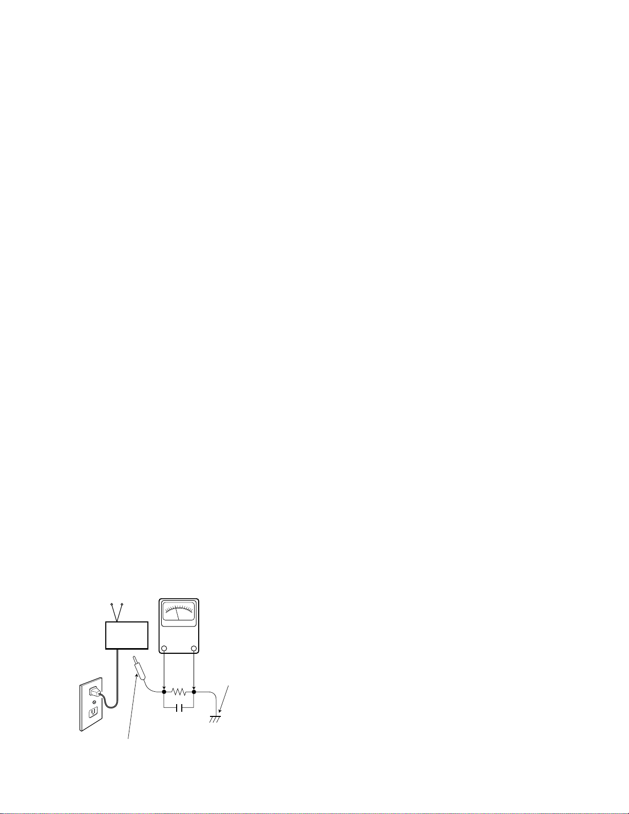
LEAKAGE CURRENT CHECK
Plug the AC line cord directly into a 120 VAC outlet. (Do not use an
isolation transformer for this check.) Use an AC voltmeter, that has
5000 ohms per volt or more sensitivity. Connect a 1500 ohm 10 watt
resistor, paralleled by a 0.15 µF 150 VAC capacitor, between a
known good earth ground (water pipe, conduit, etc.) and all
exposed metal parts of the cabinet (antennas, handle bracket, metal
cabinet, screw heads, metal overlays, control shafts, etc.). Measure
the AC voltage across the 1500 ohm resistor. The AC voltage should
not exceed 750 mV. A reading exceeding 750 mV indicates that a
dangerous potential exists. The fault must be located and corrected. Repeat the above test with the receiver power plug reversed.
NEVER RETURN A RECEIVER TO THE CUSTOMER WITHOUT
TAKING THE NECESSARY CORRECTIVE ACTION.
PRODUCT SAFETY NOTICE
When replacing components in a receiver, always keep in mind
the necessary product safety precautions. Pay special attention
to the replacement of components marked with a star () in the
parts list and in the schematic diagrams. To ensure safe product
operation, it is necessary to replace those components with the
exact same PARTS.
SERVICING ELECTROSTATICALLY SENSATIVE DEVICES
Semiconductors (solid-state devices) that can be damaged by static
electricity are referred to as Electrostatically Sensitive (ES) devices.
Examples of typical ES devices are: Integrated Circuits (IC), FieldEffect Transistors (FET), and “chip” components. The following
techniques should be observed strictly, to reduce the occurrence of
semiconductor damage due to electrostatic discharge.
1. Immediately prior to handling any semiconductor component or
an assembly containing a semiconductor device or devices, discharge the electrostatic buildup on your body by touching a
known earth ground. You may also obtain and wear a commercially available discharging wrist strap device.
CAUTION: Be sure to remove the wrist strap before applying
power to any unit being serviced.
2. After removing an ES equipped assembly, place it on a conductive surface, such as, aluminum foil, to prevent buildup or
exposure to static electricity.
3. Use only grounded-tip soldering irons to solder or unsolder ES
devices.
4. Use only anti-static solder removal devices. Some suction-type
devices can generate static electricity adequate to damage ES
devices.
5. A replacement ES device will come packaged in protective material
(conductive foam, aluminum foil, or some comparable conductive
material). Do Not remove an ES device from its protective packaging unless you are prepared to install it immediately.
6. Precisely prior to removing an ES device from its protective packaging, touch the protective packaging to the chassis or
assembly in which the device will be install
ed.
CAUTION: Be sure that no power is applied to the chassis or circuit
assembly.
7. Incidental body movements, such as, lifting a foot from a carpeted
floor or the rubbing of fabric together can generate static electricity
sufficient to damage ES devices. Therefore, minimize all body
movements while handling exposed (unpackaged) ES devices.
0.15 µF 150V AC
1500 ohm
10 watt
Good earth ground
such as a water pipe,
conduit, etc.
AC OUTLET
TELEVISION
RECEIVER
READING SHOULD NOT EXCEED 750 mV.
AC VOLTMETER
(5000 ohms per volt or more sensitivity)
To be touched to all of exposed metal parts.
Voltmeter Hook-up for Leakage Current Check.
SAFETY INSTRUCTIONS
Page 3
GENERAL
This set has an On-screen Service Menu system included in
the CPU that allows remote operation for most of the service adjustments.
ON-SCREEN SERVICE MENU SYSTEM
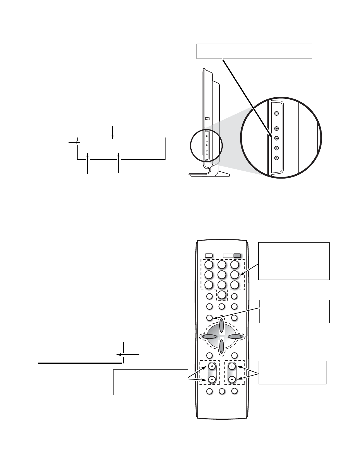
1. Enter the Service Menu:
•Turn off the receiver and disconnect the AC power
supply.
•While pressing the Volume (–) button on the televi-
sion, reconnect the AC power supply. The Service
Menu will now appear. The remote can now be used
to make adjustments. See Figure 1 below.
2. Service Adjustments:
•Press the Channel or key to select the desired
service menu item you want to adjust. See page 4
for the On-screen Service Menu.
•Use the Volume + or – key or number keys to adjust
the data.
The + or – keys will increase or decrease the data
sequentially. The number keys (0 ~ 7) toggle only
their respective bits between 1 and 0 and are used to
change the Sub-Address. For example to change bit
5 press the number 5 key. See below.
Note: Using the + or – is not recommended due to possi-
ble rapid changes.
3. Exit from the Service Menu:
•Press the MENU key to turn off the Service Menu
display.
— 3 —
SERVICE ADJUSTMENTS
(b7) (b6) (b5) (b4) (b3) (b2) (b1) (b0)
0 1 0 1 0 1 1 0
BINARY DATA
(8 bit)
Menu:
Exit Service Menu
Volume + / –:
Adjust Service Menu
Numeric:
0, 1, 2, 3, 4, 5, 6, 7:
Change Binary Data
Volume – : Enter Service Menu
080 ATT
07 00000111
Figure 1. Service Menu Display
ITEM NO.
TITLE
BINARY DATA
(8 bit)
HEX DATA
Channel :
Select Item
POWER
POWER
VOL
CH
INPUT
POWER
1
2 3
4 5 6
7 809
INFO
RECALL
TUNER MUTE
MENU
SLEEP
ENTER
VOL
CH
CAPTION EXIT
CH
VOL
RESET AUDIO PIX SHAPE
Page 4
— 4 —
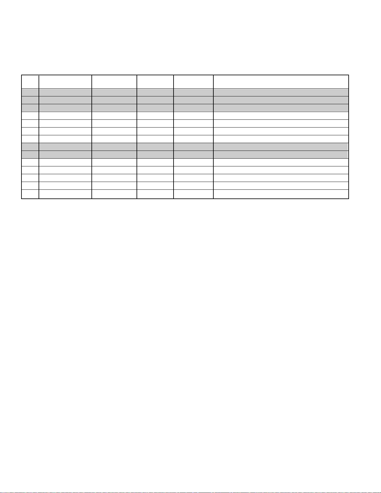
ON-SCREEN SERVICE MENU
• All data except in gray box area is fixed. Do not change for correct operation.
• Data in gray box is initial. Can be set according to adjustment information.
Table 1. ON-SCREEN SERVICE MENU
When IC802 (EEPROM) is replaced, check the bus data to confirm they are the same as below. The shaded menu should be
checked and be set up or readjusted according to the procedures described in the following pages. Initial Setup Data marked
with an * should be changed from Initial Reference Data. See page 3 for On-Screen Service Menu access and adjustments.
PROGRAM CODES
The microprossesor used in this model is a multi-purpose type and is used in several different models. To ensure proper
operation and the correct features for your particular model, the program codes must be correct.
Note 1. Option Data 1 (NO. 087 OPT) should be hexadecimal 09 (00001001 binary). See 087 above. If this program
code is wrong the TV will not operate properly.
Note 2. Option Data 2 (NO. 088 OP2) should be hexadecimal 00 (00000000 binary). See 088 above. If this program
code is wrong the TV will not operate properly.
No. TITLE
INITIAL REFERENCE INITIAL SETUP INITIAL SETUP
FUNCTION
DATA HEX DATA HEX DATA BINARY
080 ATT 07 07 00000111 Attenuation -MTS Input Level (3~0)
081 SPC 20 20 00100000 Spectral - High Separation (5~3)
082 WDB 20 20 00100000 Wide Band - Low Separation (5~0)
083 SCO 00 00 00000000 Sub Color (NOT AVAILABLE)
084 STI 00 00 00000000 Sub Tint (NOT AVAILABLE)
085 SB 00 00 00000000 Sub Bright (NOT AVAILABLE)
086 SSH 00 00 00000000 Sub Sharpness (NOT AVAILABLE)
087 OP1 09 09 00001001 b4:26=1, b3:W/HDMI=1, LCD b1,b0=0
088 OP2 00 00 00000000 b1:Aspect 16:9=1, 4:3=0
1C0 ↓↓↓00000000 Not Used
1FF ↓↓↓↓Not Used
200 1R01 00 00 00000000 ROM Correction Data
↓↓ ↓ ↓ ↓↓
298 2R48↓ 00 00 00000000 ROM Correcetion Data
Page 5
— 5 —
SERVICE ADJUSTMENTS (Continued)
MULTI-SOUND SECTION ADJUSTMENTS
Note: Multi-Sound Section must be adjusted after
A101 (U/V Tuner), IC3401 (MTS Decoder), Digital
Module or IC802 (EEPROM) is replaced.
INPUT LEVEL ADJUSTMENT
1. Connect a signal to the analog antenna terminal with
audio of 1 KH
Z 100% modulation.
2. Turn off the receiver and disconnect the AC power cord
(AC 120V line).
3. Connect voltmeter (RMS) to TP317 and ground on the
Main PC board.
4. While pressing the VOLUME – key, reconnect the AC
power cord. The Service Menu will now appear.
5. Select NO. 080 (ATT: MTS Input Level) with the
or key.
6. Adjust the + or – key for a voltmeter reading of 400 ±
20 mVrms at TP317.
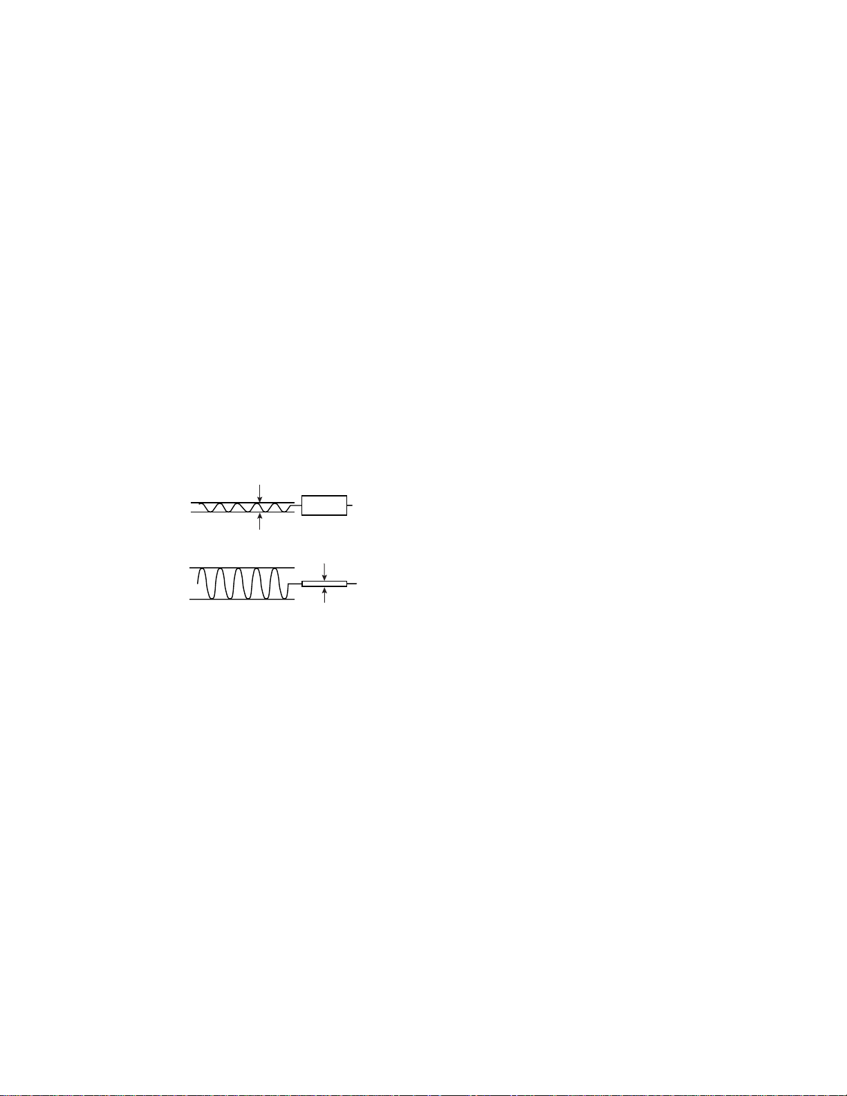
Figure 2. Separation Adjustments
SEPARATION ADJUSTMENT
7. Turn off the receiver and disconnect the AC power cord
(AC 120V line).
8. Connect oscilloscope CH1 to TP317 and CH2 to TP318
and ground.
9. Connect an MTS TV/Stereo generator to antenna terminal.
10. While pressing the VOLUME – key, reconnect the AC
power cord. The Service Menu will now appear.
11. Select pilot, 300Hz audio frequency and Left modulating
signal.
12. Select NO. 082 (WDB: Wide Band) with the or key.
13. Adjust the + or – key for minimum low frequencies at
TP317. See Figure 2.
14. Select 4 KHz audio frequency and Right modulating signal.
15. Select NO.0 81 (SPC: Spectral) with the or key.
16. Adjust the + or – key for minimum high frequencies at
TP318. See Figure 2.
Repeat adjustments (steps 11–16) until no further decreases
in amplitude can be obtained. Press the MENU key to turn
off the Service Menu display.
Minimize L leakage
TP317 (R)
300Hz
Minimize R leakage
TP318 (L)
4KHz
Page 6
— 6 —
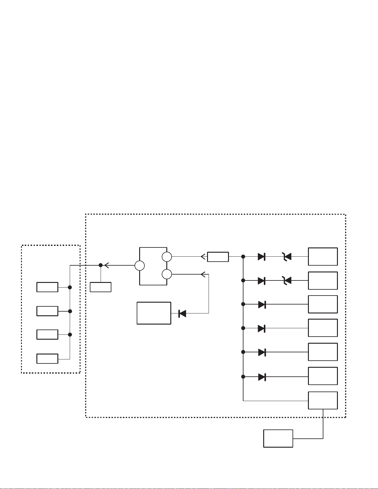
POWER FAILURE CIRCUIT
Check the following if the unit is turned off by the power
failure detector.
1. Disconnect the AC power cord (120V AC line) for at least
10 seconds.
2. Connect a DC Voltmeter to the circuits shown below.
3. Press the Power key and check for the proper voltage
supplies.
4. If any of these voltages is low, the power failure detector should turn the unit off within three seconds.
5. Check all circuits shown below.
Note: This unit is equipped with a Power Surge Protection
feature included in the CPU. If power failure occurs
three times within 15 minutes, the CPU will stop functioning automatically to help prevent secondary
damage. (TV will not turn on by pressing the power
key.) To reset the operating programs within the CPU,
disconnect the AC power cord for at least 10 seconds.
This unit is equipped with a Power Failure Detector function
included in the CPU which checks for an abnormal condition in the chassis power supplies, including the power
supply for the LVDS (LCD Panel).
If, while the power is on, a failure is caused by any of the
following that results in a low voltage supply, the CPU will
turn the unit off in 1.5 seconds to prevent further damage:
•
Failure within the power supply circuits.
•
A short circuit in the load side from the supply.
1. Power Failure: Detected voltage failure for main board
and digital board circuits. (Connected to IC801 pin 32.)
2. Power Failure (LVDS): Detected voltage failure for LCD
panel. (Connected to IC801 pin 36.)
(Normal: High; Failure: Low)
If, while the power is off, the power is switched on and any
of these failures remains uncorrected, the CPU will shut off
the power within three seconds.
Main
Power
Q602 Q1673
Q607
Q610
Q611
Power On
IC801 (CPU)
32
14
36
IC1621
5/12V
LVDS
Power Fail
Power Fail
(LVDS)
2
Q803
D1603
D1673 D1612
D1683
D1641
D1682
D1652
D1602
2
2
4,5
2
2
IC1601
3.3VD
IC1611
1.8VD
K8R
24V
IC1641
9V
IC1631
5V
D1651
33V
PIN19
K6MA
DM
Page 7
— 7 —
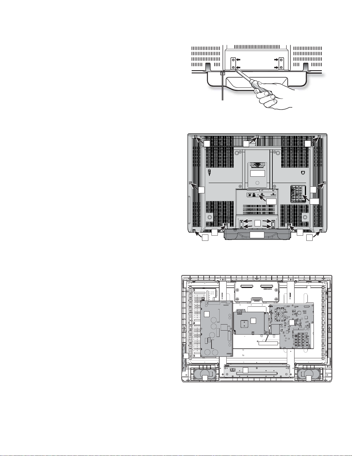
STAND REMOVAL
Note: Position TV face down on a padded or cush-
ioned surface to protect the screen and finish.
Remove 4 screws “A” to take the stand off.
MECHANICAL DISASSEMBLY
CABINET BACK REMOVAL
Remove 11 screws to take the cabinet back (C/B) off.
(B: 4X14 9pcs; B1: 3X8 1pc; B2: 4X8 1pc)
Note: The cabinet back can be removed without
removing the stand.
CAUTION: This LCD TV uses several different kinds of
screws. Using the correct screw is necessary to prevent damage. Lead wires must
be redressed to their previous locations
after servicing.
CHASSIS AND PARTS LOCATIONS
1. Digital Board
2. Main Board
3. Power Board
4. Key Switch Board
5. Speakers
6. Mounting stand (stand base)
B
B
B
C/B
B
B2
B
B1
A
B
B
3
4
STD
1
Earth Plate
B
B
2
6
5
5
Page 8
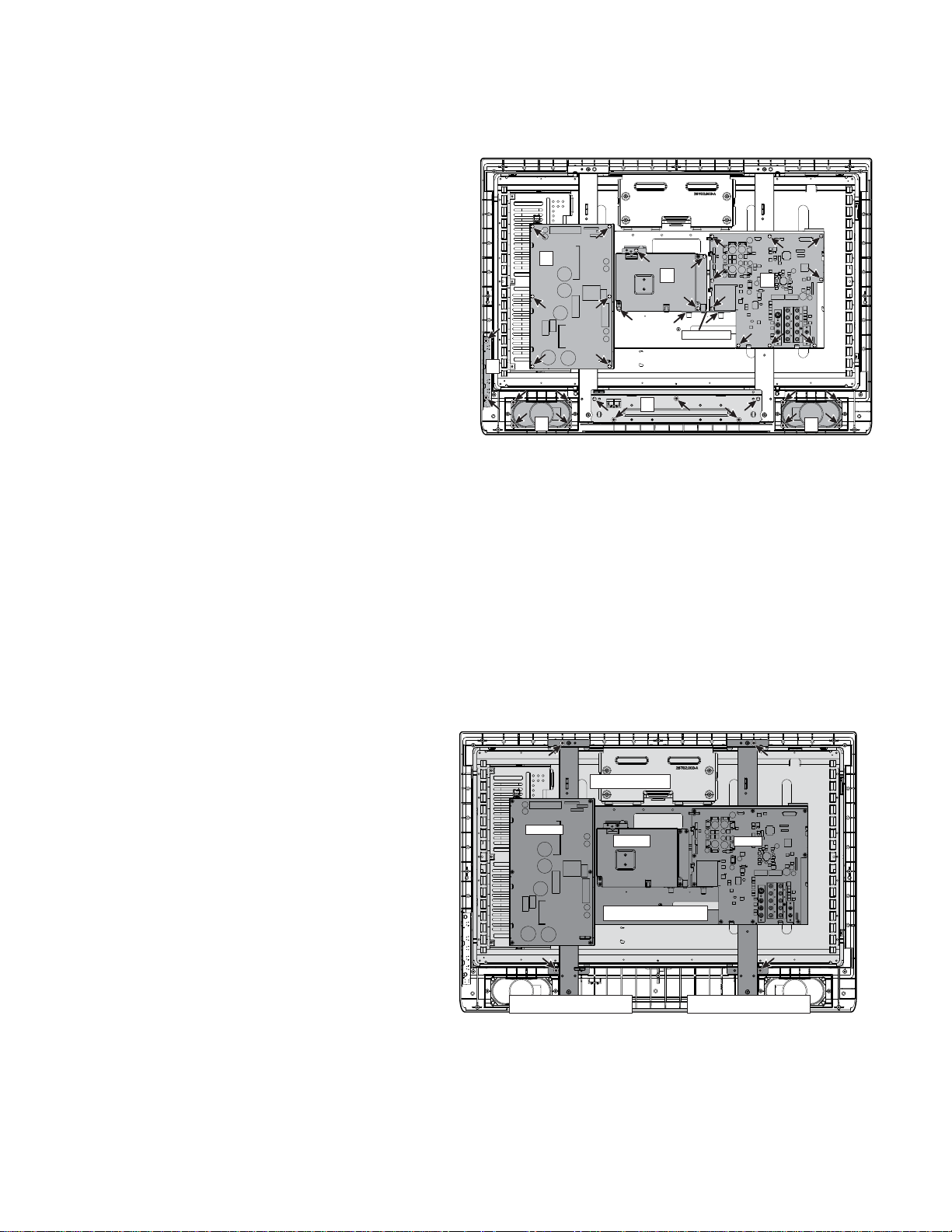
— 8 —
1: DIGITAL BOARD REMOVAL
1-1. Remove the tuner nuts from the analog and digital
tuners and remove earth plate connecting the
tuners.
1-2. Remove 4 screws (3X6) to take off the digital board.
2: MAIN BOARD REMOVAL
2-1. Remove the tuner nuts from the analog and digital
tuners and remove earth plate connecting the
tuners.
2-2. Remove 9 screws (3X6) to take off the main board.
3: POWER BOARD REMOVAL
3-1. Remove 6 screws (3X6) to take off the power board.
4: CONTROL BOARD REMOVAL
4-1. Remove 2 screws (4X14–special screw) to take off
the control board.
5: SPEAKER REMOVAL
5-1. Remove 4 screws (4X14–special screw) to take off
the speaker.
6: STAND BASE REMOVAL
6-1. Remove 5 screws to take off the stand base.
4X14–special screw 3 pcs
3X6 2 pcs.
LCD PANEL REMOVAL
1: STAND BASE REMOVAL
1-1. Remove 5 screws to take off the stand base.
See above.
2: LCD PANEL REMOVAL
2-1. Disconnect the lead wires from the LCD panel,
speakers, and control board.
2-2. Remove 4 screws (4X14–special screw) and take
off the mounting frames with the chassis plate,
power board, main board, and digital board.
2-3. Lift the LCD panel from the front cabinet.
MECHANICAL DISASSEMBLY (CONT.)
3
1
Earth Plate
4
6
5
2
5
LCD Panel
Power
Digital
Main
Chassis Plate
Mounting Frame Mounting Frame
Page 9
— 9 —
CHASSIS ELECTRICAL PARTS LIST
CAUTION: To Protect against electrical shock and for continued product safety, refer to SAFETY PRECAUTIONS,
and PRODUCT SAFETY NOTICE on Page 2.
PRODUCT SAFETY NOTICE
PRODUCT SAFETY SHOULD BE CONSIDERED WHEN A REPLACEMENT IS MADE IN ANY AREA OF A RECEIVER.
COMPONENTS INDICATED BY A STAR () IN THIS PARTS LIST AND THE SCHEMATIC DIAGRAM DESIGNATE
COMPONENTS IN WHICH SAFETY CAN BE OF SPECIAL SIGNIFICANCE. IT IS PARTICULARLY RECOMMENDED
THAT ONLY PARTS DESIGNATED ON THE FOLLOWING PARTS LIST BE USED FOR COMPONENT REPLACEMENT
DESIGNATED BY A STAR. NO DEVIATIONS FROM RESISTANCE, WATTAGE, AND VOLTAGE RATINGS MAY BE MADE
FOR REPLACEMENT ITEMS DESIGNATED BY A STAR.
Schematic
Location
Part No.
Description
Schematic
Location
Part No.
Description
Note: Schematic part location numbers may not always match with the part descriptions.
The part descriptions are correct and should be used.
CAPACITORS
RESISTORS
NOTES:
Read description of the Capacitor as follows:
(Example)
CERAMIC 100P K 50V
Rated Voltage
Tolerance Symbols:
Less than 10pF
A : Not specified B : ±0.1pF C : ±0.25pF
D : ±0.5pF E : +0 -1pF F : ±1PF
G : ±2pF H : +0.1 -0pF L : +0 -0.1pF
R : ±0.25 -0pF S : +0-0.25pF
More than 10pF
A :Not specified B : ±0.1% C : ±0.25%
D : ±0.5% F : ±1% G : ±2%
H :±3% J :±5% K :±10%
L :±15% M :±20% N :±30%
P :+100-0% Q :+30-10% T :+50-10%
U :+75-10% V :+20-10% W :+100-10%
X :+40-20% Y :+150-10% Z : +80-20%
Rated value: P=pico farad, U=micro farad
Material:
CERAMIC........... Ceramic
MT-PAPER......... Metallized Paper
POLYESTER...... Polyester
MT-POLYEST.....Metallized Polyester
POLYPRO.......... Polypropylene
MT-POLYPRO.... Metallized Polypropylene
COMPO FILM..... Composite Film
MT-COMPO........ Metallized Composite
STYRENE........... Styrene
TA-SOLID........... Tantalum Solid
AL-SOLID........... Aluminium Solid
ELECT................ Electrolytic
NP-ELECT.......... Non-polarised Electrolytic
OS-SOLID.......... Aluminium Solid with Organic
Semiconductive Electrolytic
NOTES:
Read description of the Resistor as follows:
(Example)
CARBON 4.7K J A 1/4W
Rated Wattage
Performance Symbols:
A...General B...Non-flammable
Z...Low noise
Other... Temperature coefficient
Tolerance Symbols:
A...0.05% B...0.1% C...25%
D...0.5% F...1% G...2%
J...5% K...10% M...20%
P...+5 -15%
Rated Value, ohms:
K...1,000 M...1,000,000
Material:
CARBON .............
MT-FILM ..............
OXIDE-MT ...........
SOLID ..................
MT-GLAZE ...........
WIRE WOUND .....
CERAMIC RES ....
FUSIBLE RES .....
Carbon
Metal Film
Oxide Metal Film
Composition
Metal Glaze
Wire Wound
Ceramic
Fusible
Page 10

— 10 —
Schematic
Location
Part No.
Description
Schematic
Location
Part No.
Description
MAIN PC BOARD
CAPACITORS
C002 CEXLB1E101WAN ELECT 100U M 25V
C004 CK1H472KLZBNG CERAMIC 4700P K 50V
C005 CPXLB1C100ZAN NP-ELECT 10U M 16V
C007 CK1H472KLZBNG CERAMIC 4700P K 50V
C008 CPXLB1C100ZAN NP-ELECT 10U M 16V
C009 CEXLB1H4R7WAN ELECT 4.7U M 50V
C012 CEXLB1V222WAN ELECT 2200U M 35V
C013 CEXLB1E102WAN ELECT 1000U M 25V
C014 CEXLB1E102WAN ELECT 1000U M 25V
C101 CK1H103ZLZFNG CERAMIC 0.01U Z 50V
C102 CK1H103ZLZFNG CERAMIC 0.01U Z 50V
C105 CK1H103ZLZFNG CERAMIC 0.01U Z 50V
C106 CEXLB1H470WAN ELECT 47U M 50V
C107 CEXLB1A222WAN ELECT 2200U M 10V
C805 CC1H220JLZCNG CERAMIC 22P J 50V
C806 CC1H220JLZCNG CERAMIC 22P J 50V
C807 CK1H103ZLZFNG CERAMIC 0.01U Z 50V
C811 CK1H104ZLZFNG CERAMIC 0.1U Z 50V
C813 CEXLB1A470WAN ELECT 47U M 10V
C814 CK1H222KLZBNG CERAMIC 2200P K 50V
C815 CC1H220JLZCNG CERAMIC 22P J 50V
C816 CC1H220JLZCNG CERAMIC 22P J 50V
C820 CK1H103ZLZFNG CERAMIC 0.01U Z 50V
C825 CC1H330JLZCNG CERAMIC 33P J 50V
C826 CK1H104ZLZFNG CERAMIC 0.1U Z 50V
C827 CK1H104ZLZFNG CERAMIC 0.1U Z 50V
C829 CK1H104ZLZFNG CERAMIC 0.1U Z 50V
C834 CEXLB0J471WAN ELECT 470U M 6.3V
C835 CK1H104ZLZFNG CERAMIC 0.1U Z 50V
C836 CC1H120JLZCNG CERAMIC 12P J 50V
C837 CC1H120JLZCNG CERAMIC 12P J 50V
C838 CK1H104ZLZFNG CERAMIC 0.1U Z 50V
C839 CK1H103ZLZFNG CERAMIC 0.01U Z 50V
C840 CK1H333KLZBNG CERAMIC 0.033U K 50V
C841 CEXLB1H2R2WAN ELECT 2.2U M 50V
C842 CK1H104ZLZFNG CERAMIC 0.1U Z 50V
C1001 CK1H104ZLZFNG CERAMIC 0.1U Z 50V
C1002 CEXLB1C100WAN ELECT 10U M 16V
C1003 CEXLB1C100WAN ELECT 10U M 16V
C1004 CEXLB1H2R2WAN ELECT 2.2U M 50V
C1005 CEXLB1H2R2WAN ELECT 2.2U M 50V
C1021 CEXLB1C101WAN ELECT 100U M 16V
C1022 CEXLB1C100WAN ELECT 10U M 16V
C1023 CEXLB1C100WAN ELECT 10U M 16V
C1024 CK1H104ZLZFNG CERAMIC 0.1U Z 50V
C1025 CEXLB1C100WAN ELECT 10U M 16V
C1026 CEXLB1H2R2WAN ELECT 2.2U M 50V
C1027 CEXLB1H2R2WAN ELECT 2.2U M 50V
C1061 CEXLB1C331WAN ELECT 330U M 16V
C1062 CEXLB1C100WAN ELECT 10U M 16V
C1063 CEXLB1C100WAN ELECT 10U M 16V
C1064 CK1H104ZLZFNG CERAMIC 0.1U Z 50V
C1065 CEXLB1C100WAN ELECT 10U M 16V
C1066 CEXLB1H2R2WAN ELECT 2.2U M 50V
C1067 CEXLB1H2R2WAN ELECT 2.2U M 50V
C1101 CEXLB1E4R7WAN ELECT 4.7U M 25V
C1102 CEXLB1E4R7WAN ELECT 4.7U M 25V
C1201 CEXLB1C101WAN ELECT 100U M 16V
C1202 CK1H104ZLZFNG CERAMIC 0.1U Z 50V
C1203 CEXLB1H100WAN ELECT 10U M 50V
C1204 CK1H104ZLZFNG CERAMIC 0.1U Z 50V
C1251 CK1H104ZLZFNG CERAMIC 0.1U Z 50V
C1252 CK1H104ZLZFNG CERAMIC 0.1U Z 50V
C1601 CEXLB1C102WAN ELECT 1000U M 16V
C1602 CK1H104ZLZFNG CERAMIC 0.1U Z 50V
C1604 CEXLB0J102WAN ELECT 1000U M 6.3V
C1605 CH1H105JAGANN MT-COMPO 1U J 50V
C1611 CEXLB1C102WAN ELECT 1000U M 16V
C1612 CK1H104ZLZFNG CERAMIC 0.1U Z 50V
C1614 CEXLB0J102WAN ELECT 1000U M 6.3V
C1615 CH1H105JAGANN MT-COMPO 1U J 50V
C1641 CEXLB1C102WAN ELECT 1000U M 16V
C1642 CK1H104ZLZFNG CERAMIC 0.1U Z 50V
C1643 CK1H104ZLZFNG CERAMIC 0.1U Z 50V
C1644 CEXLB1C102WAN ELECT 1000U M 16V
C1651 CEXLB1C101WAN ELECT 100U M 16V
C1652 CK1H104ZLZFNG CERAMIC 0.1U Z 50V
C1653 CEXLB1E4R7WAN ELECT 4.7U M 25V
C1654 CEXLB1H101WAN ELECT 100U M 50V
C1655 CK1H104ZLZFNG CERAMIC 0.1U Z 50V
C1656 CK1H102KLZBNG CERAMIC 1000P K 50V
C1657 CK1H104ZLZFNG CERAMIC 0.1U Z 50V
C1661 CK1H104ZLZFNG CERAMIC 0.1U Z 50V
C1662 CK1H103ZLZFNG CERAMIC 0.01U Z 50V
C1663 CK1H102KLZBNG CERAMIC 1000P K 50V
C1664 CK1H103ZLZFNG CERAMIC 0.01U Z 50V
C1665 CK1H104ZLZFNG CERAMIC 0.1U Z 50V
C1666 CK1H104ZLZFNG CERAMIC 0.1U Z 50V
C1681 CEXLB1C102WAN ELECT 1000U M 16V
C1682 CK1H104ZLZFNG CERAMIC 0.1U Z 50V
C1684 CEXLB1A102WAN ELECT 1000U M 10V
C1685 CH1H105JAGANN MT-COMPO 1U J 50V
C1691 CEXLB1V102WAN ELECT 1000U M 35V
C1694 CEXLB1V471WAN ELECT 470U M 35V
C1695 CH1H105JAGANN MT-COMPO 1U J 50V
C1696 CEXLB1C100WAN ELECT 10U M 16V
C1697 CK1H104ZLZFNG CERAMIC 0.1U Z 50V
C1801 CK1H104ZLZFNG CERAMIC 0.1U Z 50V
C1851 CK1H104ZLZFNG CERAMIC 0.1U Z 50V
C1852 CK1H104ZLZFNG CERAMIC 0.1U Z 50V
C1853 CK1H104ZLZFNG CERAMIC 0.1U Z 50V
C1854 CK1H104ZLZFNG CERAMIC 0.1U Z 50V
C1855 CK1H104ZLZFNG CERAMIC 0.1U Z 50V
C3401 CPXLB1H4R7ZAN NP-ELECT 4.7U M 50V
Page 11

— 11 —
Schematic
Location
Part No.
Description
Schematic
Location
Part No.
Description
C3402 CEXLB1HR10WAN ELECT 0.1U M 50V
C3403 CPXLB1H4R7ZAN NP-ELECT 4.7U M 50V
C3404 CK1H562KLZBNG CERAMIC 5600P K 50V
C3405 CK1H123KLZBNG CERAMIC 0.012U K 50V
C3406 CEXLB1H1R0WAN ELECT 1U M 50V
C3407 CEXLB1HR47WAN ELECT 0.47U M 50V
C3408 CEXLB1C470WAN ELECT 47U M 16V
C3409 CEXLB1E4R7WAN ELECT 4.7U M 25V
C3410 CK1H104ZLZFNG CERAMIC 0.1U Z 50V
C3411 CPXLB1H4R7ZAN NP-ELECT 4.7U M 50V
C3412 CEXLB1E4R7WAN ELECT 4.7U M 25V
C3413 CEXLB1C102WAN ELECT 1000U M 16V
C3414 CPXLB1H4R7ZAN NP-ELECT 4.7U M 50V
C3415 CK1H272KLZBNG CERAMIC 2700P K 50V
C3416 CK1H473KLZBNG CERAMIC 0.047U K 50V
C3417 CT1A3R3KDRANG TA-SOLID 3.3U K 10V
C3418 CPXLB1H4R7ZAN NP-ELECT 4.7U M 50V
C3419 CT1A100KDRANG TA-SOLID 10U K 10V
C3420 CEXLB1H1R0WAN ELECT 1U M 50V
C3421 CEXLB1H1R0WAN ELECT 1U M 50V
C3422 CEXLB1H1R0WAN ELECT 1U M 50V
C3423 CEXLB1H1R0WAN ELECT 1U M 50V
C3424 CEXLB1H1R0WAN ELECT 1U M 50V
C3425 CK1H223KLZBNG CERAMIC 0.022U K 50V
C3426 CK1H472KLZBNG CERAMIC 4700P K 50V
C3427 CPXLB1H4R7ZAN NP-ELECT 4.7U M 50V
C3428 CEXLB1HR10WAN ELECT 0.1U M 50V
C3429 CK1H472KLZBNG CERAMIC 4700P K 50V
C3430 CEXLB1C471WAN ELECT 470U M 16V
DIODES
D002 DDRM11C-----N DIODE RM11C
D801 DD1SS355----G DIODE 1SS355 TE-17
D802 DZUDZS6.2B--G ZENER DIODE UDZS6.2B TE-17
D803 DD1SS355----G DIODE 1SS355 TE-17
D810 DD1SS355----G DIODE 1SS355 TE-17
D811 DD1SS355----G DIODE 1SS355 TE-17
D1601 DDYG812S04R-N DIODE YG812S04R
D1602 DZUDZS3.0B--G ZD UDZS3.0B-TE-17
D1603 DD1SS355----G DIODE 1SS355 TE-17
D1611 DDYG812S04R-N DIODE YG812S04R
D1612 DZUDZS3.6B--G ZD UDZS-TE-173.6B
D1641 DD1SS355----G DIODE 1SS355 TE-17
D1651 DDRB500V-40-G DIODE RB500V-40-TE-17
D1652 DD1SS355----G DIODE 1SS355 TE-17
D1673 DD1SS355----G DIODE 1SS355 TE-17
D1681 DDRK46-304--N DIODE RK46 015-304
D1682 DD1SS355----G DIODE 1SS355 TE-17
D1683 DD1SS355----G DIODE 1SS355 TE-17
D1691 DDYG812S04R-N DIODE YG812S04R
D1692 DD1SS355----G DIODE 1SS355 TE-17
D1693 DD1SS355----G DIODE 1SS355 TE-17
D3401 DDSB07-03C--P DIODE SB07-03C-TB
INTEGRATED CIRCUITS
IC001 QLA42052-E--N IC LA42052-E
IC801 QXXAAJQ0724-- IC LC87F4164AU-LCD001
IC801 QXXAVC755---M IC LC8741XXXA
IC802 Q24LC08BT/SNP IC 24LC08BT/SN
IC803 QMN1381-Q---N IC MN1381-Q
IC805 QTC7SH08F---P IC TC7SH08F(TE85L, F)
IC806 QTC7SET08F--P IC TC7SET08F-TE85L
IC1201 QCD4052BNSR-P IC CD4052BNSR
QTC4052BF---P IC TC4052BF-EL
IC1251 QCD4052BNSR-P IC CD4052BNSR
QTC4052BF---P IC TC4052BF-EL
IC1601 QLA5774-E---N IC QLA5774-E---M
IC1611 QLA5774-E---N IC QLA5774-E---M
IC1621 QLA5774-E---N IC QLA5774-E---M
IC1631 QLA5774-E---N IC QLA5774-E---M
IC1641 QXXAVB833---N IC SI-3090FA LF1113
IC1651 QFA7700V----G IC FA7700V-TE1
IC3401 QCXA2234Q---P IC CXA2234Q-T6
COILS
L001 1AV4L26B2770G INDUCTOR, 220 OHM
L003 RGFR000ZTAANL MT-GLAZE0.000 ZA 1/10W
L005 RGFR000ZTAANL MT-GLAZE0.000 ZA 1/10W
L006 RGFR000ZTAANL MT-GLAZE0.000 ZA 1/10W
L007 RGFR000ZTAANL MT-GLAZE0.000 ZA 1/10W
L100 1AV4L2FB150MG INDUCTOR, 15U M
L101 1AV4L2FB150MG INDUCTOR, 15U M
L102 1AV4L2FB3R3MG INDUCTOR, 3.3U M
L103 RGFR000ZTAANL MT-GLAZE0.000 ZA 1/10W
L104 RGFR000ZTAANL MT-GLAZE0.000 ZA 1/10W
L105 RGFR000ZTAANL MT-GLAZE0.000 ZA 1/10W
L106 RGFR000ZTAANL MT-GLAZE0.000 ZA 1/10W
L107 RGFR000ZTAANL MT-GLAZE0.000 ZA 1/10W
L108 RGFR000ZTAANL MT-GLAZE0.000 ZA 1/10W
L801 1AV4L26B2770G INDUCTOR, 220 OHM
L802 1AV4L26B2770G INDUCTOR, 220 OHM
L803 1AV4L2FB3R3MG INDUCTOR, 3.3U M
L804 1AV4L2FB3R3MG INDUCTOR, 3.3U M
L805 1AV4L26B2770G INDUCTOR, 220 OHM
L806 1AV4L26B2770G INDUCTOR, 220 OHM
L1001 RGFR000ZTAANL MT-GLAZE0.000 ZA 1/10W
L1021 1AV4L2FB150MG INDUCTOR, 15U M
L1101 RGFR000ZTAANL MT-GLAZE0.000 ZA 1/10W
L1201 1AV4L2FB3R3MG INDUCTOR, 3.3U M
L1251 RGFR000ZTAANL MT-GLAZE0.000 ZA 1/10W
L1601 1AV4L26B2770G INDUCTOR, 220 OHM
L1602 1AV4L26B2770G INDUCTOR, 220 OHM
L1603 1AV4L2JJ470KN INDUCTOR, 47U K
L1604 RGFR000ZTAANL MT-GLAZE0.000 ZA 1/10W
L1605 RGFR000ZTAANL MT-GLAZE0.000 ZA 1/10W
L1606 RGFR000ZTAANL MT-GLAZE0.000 ZA 1/10W
L1607 RGFR000ZTAANL MT-GLAZE0.000 ZA 1/10W
Page 12

— 12 —
Schematic
Location
Part No.
Description
Schematic
Location
Part No.
Description
L1608 RGFR000ZTAANL MT-GLAZE0.000 ZA 1/10W
L1609 RGFR000ZTAANL MT-GLAZE0.000 ZA 1/10W
L1610 RGFR000ZTAANL MT-GLAZE0.000 ZA 1/10W
L1611 1AV4L26B2770G INDUCTOR, 220 OHM
L1612 1AV4L26B2770G INDUCTOR, 220 OHM
L1613 1AV4L2JJ330MN INDUCTOR, 33U M
L1621 1AV4L26B2770G INDUCTOR, 220 OHM
L1624 RGFR000ZTAANL MT-GLAZE0.000 ZA 1/10W
L1625 RGFR000ZTAANL MT-GLAZE0.000 ZA 1/10W
L1626 RGFR000ZTAANL MT-GLAZE0.000 ZA 1/10W
L1627 RGFR000ZTAANL MT-GLAZE0.000 ZA 1/10W
L1628 RGFR000ZTAANL MT-GLAZE0.000 ZA 1/10W
L1630 RGFR000ZTAANL MT-GLAZE0.000 ZA 1/10W
L1631 RGFR000ZTAANL MT-GLAZE0.000 ZA 1/10W
L1632 1AV4L2JJ470KN INDUCTOR, 47U K
L1635 RGFR000ZTAANL MT-GLAZE0.000 ZA 1/10W
L1641 RGFR000ZTAANL MT-GLAZE0.000 ZA 1/10W
L1642 RGFR000ZTAANL MT-GLAZE0.000 ZA 1/10W
L1643 RGFR000ZTAANL MT-GLAZE0.000 ZA 1/10W
L1644 RGFR000ZTAANL MT-GLAZE0.000 ZA 1/10W
L1651 RGFR000ZTAANL MT-GLAZE0.000 ZA 1/10W
L1652 1AV4L2PX222JG INDUCTOR, 2.2M J
L1658 RGFR000ZTAANL MT-GLAZE0.000 ZA 1/10W
L1659 RGFR000ZTAANL MT-GLAZE0.000 ZA 1/10W
L1661 RGFR000ZTAANL MT-GLAZE0.000 ZA 1/10W
L1663 RGFR000ZTAANL MT-GLAZE0.000 ZA 1/10W
L1664 RGFR000ZTAANL MT-GLAZE0.000 ZA 1/10W
L1665 RGFR000ZTAANL MT-GLAZE0.000 ZA 1/10W
L1666 RGFR000ZTAANL MT-GLAZE0.000 ZA 1/10W
L1667 RGFR000ZTAANL MT-GLAZE0.000 ZA 1/10W
L1668 RGFR000ZTAANL MT-GLAZE0.000 ZA 1/10W
L1669 RGFR000ZTAANL MT-GLAZE0.000 ZA 1/10W
L1670 1AV4L26B2770G INDUCTOR, 220 OHM
L1671 RGFR000ZTAANL MT-GLAZE0.000 ZA 1/10W
L1673 RGFR000ZTAANL MT-GLAZE0.000 ZA 1/10W
L1674 1AV4L26B2770G INDUCTOR, 220 OHM
L1675 1AV4L26B2770G INDUCTOR, 220 OHM
L1676 1AV4L26B2770G INDUCTOR, 220 OHM
L1677 1AV4L26B2770G INDUCTOR, 220 OHM
L1678 1AV4L26B2770G INDUCTOR, 220 OHM
L1679 1AV4L26B2770G INDUCTOR, 220 OHM
L1682 1AV4L26B2770G INDUCTOR, 220 OHM
L1683 1AV4L2JJ330MN INDUCTOR, 33U M
L1684 RGFR000ZTAANL MT-GLAZE0.000 ZA 1/10W
L1685 RGFR000ZTAANL MT-GLAZE0.000 ZA 1/10W
L1687 RGFR000ZTAANL MT-GLAZE0.000 ZA 1/10W
L1801 1AV4L26B2770G INDUCTOR, 220 OHM
L2803 RGFR000ZTAANL MT-GLAZE0.000 ZA 1/10W
L3401 1AV4L2FB3R3MG INDUCTOR, 3.3U M
TRANSISTORS
Q001 T2SC2412K-R-P TR 2SC2412K-T-96-R
T2SC2412K-S-P TR 2SC2412K-T-96-S
T2SC2812-L6-P TR 2SC2812-L6-TB
T2SC2812-L7-P TR 2SC2812-L7-TB
T2SC2812N-L6P TR 2SC2812N-L6-TB
T2SC2812N-L7P TR 2SC2812N-L7-TB
T2SC3928A1R-P TR 2SC3928A1R
T2SC3928A1S-P TR 2SC3928A1S
Q101 T2SC2412K-R-P TR 2SC2412K-T-96-R
T2SC2412K-S-P TR 2SC2412K-T-96-S
T2SC2812-L6-P TR 2SC2812-L6-TB
T2SC2812-L7-P TR 2SC2812-L7-TB
T2SC2812N-L6P TR 2SC2812N-L6-TB
T2SC2812N-L7P TR 2SC2812N-L7-TB
T2SC3928A1R-P TR 2SC3928A1R
T2SC3928A1S-P TR 2SC3928A1S
Q801 T2SC2412K-R-P TR 2SC2412K-T-96-R
T2SC2412K-S-P TR 2SC2412K-T-96-S
T2SC2812-L6-P TR 2SC2812-L6-TB
T2SC2812-L7-P TR 2SC2812-L7-TB
T2SC2812N-L6P TR 2SC2812N-L6-TB
T2SC2812N-L7P TR 2SC2812N-L7-TB
T2SC3928A1R-P TR 2SC3928A1R
T2SC3928A1S-P TR 2SC3928A1S
Q803 T2SC2412K-R-P TR 2SC2412K-T-96-R
T2SC2412K-S-P TR 2SC2412K-T-96-S
T2SC2812-L6-P TR 2SC2812-L6-TB
T2SC2812-L7-P TR 2SC2812-L7-TB
T2SC2812N-L6P TR 2SC2812N-L6-TB
T2SC2812N-L7P TR 2SC2812N-L7-TB
T2SC3928A1R-P TR 2SC3928A1R
T2SC3928A1S-P TR 2SC3928A1S
Q804 T2SA1037AK-RP TR 2SA1037AK T146 R
T2SA1037AK-SP TR 2SA1037AK T146 S
T2SA1037K-R-P TR 2SA1037K-T-96-R
T2SA1037K-S-P TR 2SA1037K-T-96-S
T2SA1179-M6-P TR 2SA1179-M6
T2SA1179-M7-P TR 2SA1179-M7-TB
T2SA1179N-M6P TR 2SA1179N-M6-TB
T2SA1179N-M7P TR 2SA1179N-M7-TB
T2SA1235A1E-P TR 2SA1235A1E
T2SA1235A1F-P TR 2SA1235A1F
Q805 T2SC2412K-R-P TR 2SC2412K-T-96-R
T2SC2412K-S-P TR 2SC2412K-T-96-S
T2SC2812-L6-P TR 2SC2812-L6-TB
T2SC2812-L7-P TR 2SC2812-L7-TB
T2SC2812N-L6P TR 2SC2812N-L6-TB
T2SC2812N-L7P TR 2SC2812N-L7-TB
T2SC3928A1R-P TR 2SC3928A1R
T2SC3928A1S-P TR 2SC3928A1S
Page 13

— 13 —
Schematic
Location
Part No.
Description
Schematic
Location
Part No.
Description
Q810 T2SC2412K-R-P TR 2SC2412K-T-96-R
T2SC2412K-S-P TR 2SC2412K-T-96-S
T2SC2812-L6-P TR 2SC2812-L6-TB
T2SC2812-L7-P TR 2SC2812-L7-TB
T2SC2812N-L6P TR 2SC2812N-L6-TB
T2SC2812N-L7P TR 2SC2812N-L7-TB
T2SC3928A1R-P TR 2SC3928A1R
T2SC3928A1S-P TR 2SC3928A1S
Q811 T2SC2411K-Q-P TR 2SC2411K-T146-Q
Q1021 T2SA1037AK-RP TR 2SA1037AK T146 R
T2SA1037AK-SP TR 2SA1037AK T146 S
T2SA1037K-R-P TR 2SA1037K-T-96-R
T2SA1037K-S-P TR 2SA1037K-T-96-S
T2SA1179-M6-P TR 2SA1179-M6
T2SA1179-M7-P TR 2SA1179-M7-TB
T2SA1179N-M6P TR 2SA1179N-M6-TB
T2SA1179N-M7P TR 2SA1179N-M7-TB
T2SA1235A1E-P TR 2SA1235A1E
T2SA1235A1F-P TR 2SA1235A1F
Q1022 T2SA1037AK-RP TR 2SA1037AK T146 R
T2SA1037AK-SP TR 2SA1037AK T146 S
T2SA1037K-R-P TR 2SA1037K-T-96-R
T2SA1037K-S-P TR 2SA1037K-T-96-S
T2SA1179-M6-P TR 2SA1179-M6
T2SA1179-M7-P TR 2SA1179-M7-TB
T2SA1179N-M6P TR 2SA1179N-M6-TB
T2SA1179N-M7P TR 2SA1179N-M7-TB
T2SA1235A1E-P TR 2SA1235A1E
T2SA1235A1F-P TR 2SA1235A1F
Q1023 T2SA1037AK-RP TR 2SA1037AK T146 R
T2SA1037AK-SP TR 2SA1037AK T146 S
T2SA1037K-R-P TR 2SA1037K-T-96-R
T2SA1037K-S-P TR 2SA1037K-T-96-S
T2SA1179-M6-P TR 2SA1179-M6
T2SA1179-M7-P TR 2SA1179-M7-TB
T2SA1179N-M6P TR 2SA1179N-M6-TB
T2SA1179N-M7P TR 2SA1179N-M7-TB
T2SA1235A1E-P TR 2SA1235A1E
T2SA1235A1F-P TR 2SA1235A1F
Q1061 T2SA1037AK-RP TR 2SA1037AK T146 R
T2SA1037AK-SP TR 2SA1037AK T146 S
T2SA1037K-R-P TR 2SA1037K-T-96-R
T2SA1037K-S-P TR 2SA1037K-T-96-S
T2SA1179-M6-P TR 2SA1179-M6
T2SA1179-M7-P TR 2SA1179-M7-TB
T2SA1179N-M6P TR 2SA1179N-M6-TB
T2SA1179N-M7P TR 2SA1179N-M7-TB
T2SA1235A1E-P TR 2SA1235A1E
T2SA1235A1F-P TR 2SA1235A1F
Q1062 T2SA1037AK-RP TR 2SA1037AK T146 R
T2SA1037AK-SP TR 2SA1037AK T146 S
T2SA1037K-R-P TR 2SA1037K-T-96-R
T2SA1037K-S-P TR 2SA1037K-T-96-S
T2SA1179-M6-P TR 2SA1179-M6
T2SA1179-M7-P TR 2SA1179-M7-TB
T2SA1179N-M6P TR 2SA1179N-M6-TB
T2SA1179N-M7P TR 2SA1179N-M7-TB
T2SA1235A1E-P TR 2SA1235A1E
T2SA1235A1F-P TR 2SA1235A1F
Q1063 T2SA1037AK-RP TR 2SA1037AK T146 R
T2SA1037AK-SP TR 2SA1037AK T146 S
T2SA1037K-R-P TR 2SA1037K-T-96-R
T2SA1037K-S-P TR 2SA1037K-T-96-S
T2SA1179-M6-P TR 2SA1179-M6
T2SA1179-M7-P TR 2SA1179-M7-TB
T2SA1179N-M6P TR 2SA1179N-M6-TB
T2SA1179N-M7P TR 2SA1179N-M7-TB
T2SA1235A1E-P TR 2SA1235A1E
T2SA1235A1F-P TR 2SA1235A1F
Q1101 T2SC2412K-R-P TR 2SC2412K-T-96-R
T2SC2412K-S-P TR 2SC2412K-T-96-S
T2SC2812-L6-P TR 2SC2812-L6-TB
T2SC2812-L7-P TR 2SC2812-L7-TB
T2SC2812N-L6P TR 2SC2812N-L6-TB
T2SC2812N-L7P TR 2SC2812N-L7-TB
T2SC3928A1R-P TR 2SC3928A1R
T2SC3928A1S-P TR 2SC3928A1S
Q1102 T2SC2412K-R-P TR 2SC2412K-T-96-R
T2SC2412K-S-P TR 2SC2412K-T-96-S
T2SC2812-L6-P TR 2SC2812-L6-TB
T2SC2812-L7-P TR 2SC2812-L7-TB
T2SC2812N-L6P TR 2SC2812N-L6-TB
T2SC2812N-L7P TR 2SC2812N-L7-TB
T2SC3928A1R-P TR 2SC3928A1R
T2SC3928A1S-P TR 2SC3928A1S
Q1201 T2SC2412K-R-P TR 2SC2412K-T-96-R
T2SC2412K-S-P TR 2SC2412K-T-96-S
T2SC2812-L6-P TR 2SC2812-L6-TB
T2SC2812-L7-P TR 2SC2812-L7-TB
T2SC2812N-L6P TR 2SC2812N-L6-TB
T2SC2812N-L7P TR 2SC2812N-L7-TB
T2SC3928A1R-P TR 2SC3928A1R
T2SC3928A1S-P TR 2SC3928A1S
Q1202 T2SC2412K-R-P TR 2SC2412K-T-96-R
T2SC2412K-S-P TR 2SC2412K-T-96-S
T2SC2812-L6-P TR 2SC2812-L6-TB
T2SC2812-L7-P TR 2SC2812-L7-TB
T2SC2812N-L6P TR 2SC2812N-L6-TB
T2SC2812N-L7P TR 2SC2812N-L7-TB
T2SC3928A1R-P TR 2SC3928A1R
T2SC3928A1S-P TR 2SC3928A1S
Q1251 T2SC2412K-R-P TR 2SC2412K-T-96-R
T2SC2412K-S-P TR 2SC2412K-T-96-S
T2SC2812-L6-P TR 2SC2812-L6-TB
T2SC2812-L7-P TR 2SC2812-L7-TB
T2SC2812N-L6P TR 2SC2812N-L6-TB
T2SC2812N-L7P TR 2SC2812N-L7-TB
T2SC3928A1R-P TR 2SC3928A1R
Page 14

— 14 —
Schematic
Location
Part No.
Description
Schematic
Location
Part No.
Description
Q1251(Cont.) T2SC3928A1S-P TR 2SC3928A1S
Q1252 T2SC2412K-R-P TR 2SC2412K-T-96-R
T2SC2412K-S-P TR 2SC2412K-T-96-S
T2SC2812-L6-P TR 2SC2812-L6-TB
T2SC2812-L7-P TR 2SC2812-L7-TB
T2SC2812N-L6P TR 2SC2812N-L6-TB
T2SC2812N-L7P TR 2SC2812N-L7-TB
T2SC3928A1R-P TR 2SC3928A1R
T2SC3928A1S-P TR 2SC3928A1S
Q1621 T2SC2412K-R-P TR 2SC2412K-T-96-R
T2SC2412K-S-P TR 2SC2412K-T-96-S
T2SC2812-L6-P TR 2SC2812-L6-TB
T2SC2812-L7-P TR 2SC2812-L7-TB
T2SC2812N-L6P TR 2SC2812N-L6-TB
T2SC2812N-L7P TR 2SC2812N-L7-TB
T2SC3928A1R-P TR 2SC3928A1R
T2SC3928A1S-P TR 2SC3928A1S
Q1651 T5HN01C-----P TR 5HN01C-TL
Q1672 T2SC2412K-R-P TR 2SC2412K-T-96-R
T2SC2412K-S-P TR 2SC2412K-T-96-S
T2SC2812-L6-P TR 2SC2812-L6-TB
T2SC2812-L7-P TR 2SC2812-L7-TB
T2SC2812N-L6P TR 2SC2812N-L6-TB
T2SC2812N-L7P TR 2SC2812N-L7-TB
T2SC3928A1R-P TR 2SC3928A1R
T2SC3928A1S-P TR 2SC3928A1S
Q1673 T2SC2412K-R-P TR 2SC2412K-T-96-R
T2SC2412K-S-P TR 2SC2412K-T-96-S
T2SC2812-L6-P TR 2SC2812-L6-TB
T2SC2812-L7-P TR 2SC2812-L7-TB
T2SC2812N-L6P TR 2SC2812N-L6-TB
T2SC2812N-L7P TR 2SC2812N-L7-TB
T2SC3928A1R-P TR 2SC3928A1R
T2SC3928A1S-P TR 2SC3928A1S
Q1690 T2SA1037AK-RP TR 2SA1037AK T146 R
T2SA1037AK-SP TR 2SA1037AK T146 S
T2SA1037K-R-P TR 2SA1037K-T-96-R
T2SA1037K-S-P TR 2SA1037K-T-96-S
T2SA1179-M6-P TR 2SA1179-M6
T2SA1179-M7-P TR 2SA1179-M7-TB
T2SA1179N-M6P TR 2SA1179N-M6-TB
T2SA1179N-M7P TR 2SA1179N-M7-TB
T2SA1235A1E-P TR 2SA1235A1E
T2SA1235A1F-P TR 2SA1235A1F
Q1691 T2SC2411K-Q-P TR 2SC2411K-T146-Q
Q3403 T2SC2412K-R-P TR 2SC2412K-T-96-R
T2SC2412K-S-P TR 2SC2412K-T-96-S
T2SC2812-L6-P TR 2SC2812-L6-TB
T2SC2812-L7-P TR 2SC2812-L7-TB
T2SC2812N-L6P TR 2SC2812N-L6-TB
T2SC2812N-L7P TR 2SC2812N-L7-TB
T2SC3928A1R-P TR 2SC3928A1R
T2SC3928A1S-P TR 2SC3928A1S
Q3404 T2SC2412K-R-P TR 2SC2412K-T-96-R
T2SC2412K-S-P TR 2SC2412K-T-96-S
T2SC2812-L6-P TR 2SC2812-L6-TB
T2SC2812-L7-P TR 2SC2812-L7-TB
T2SC2812N-L6P TR 2SC2812N-L6-TB
T2SC2812N-L7P TR 2SC2812N-L7-TB
T2SC3928A1R-P TR 2SC3928A1R
T2SC3928A1S-P TR 2SC3928A1S
Q3405 T2SC2412K-R-P TR 2SC2412K-T-96-R
T2SC2412K-S-P TR 2SC2412K-T-96-S
T2SC2812-L6-P TR 2SC2812-L6-TB
T2SC2812-L7-P TR 2SC2812-L7-TB
T2SC2812N-L6P TR 2SC2812N-L6-TB
T2SC2812N-L7P TR 2SC2812N-L7-TB
T2SC3928A1R-P TR 2SC3928A1R
T2SC3928A1S-P TR 2SC3928A1S
RESISTORS
R001 RGF1000JTCANL MT-GLAZE 100 JA 1/10W
R002 RGF3300JTCANL MT-GLAZE 330 JA 1/10W
R003 RGF8201JTCANL MT-GLAZE 8.2K JA 1/10W
R004 RGF3301JTCANL MT-GLAZE 3.3K JA 1/10W
R005 RGF8201JTCANL MT-GLAZE 8.2K JA 1/10W
R006 RGF3301JTCANL MT-GLAZE 3.3K JA 1/10W
R007 RWXAA5270JKAN WIRE WOUND 27 JA 5W
R008 RWXAA5270JKAN WIRE WOUND 27 JA 5W
R009 RGF1502JTCANL MT-GLAZE 15K JA 1/10W
R014 RGF1001JTCANL MT-GLAZE 1K JA 1/10W
R101 RGF1000JTCANL MT-GLAZE 100 JA 1/10W
R102 RGF1000JTCANL MT-GLAZE 100 JA 1/10W
R103 RGF1000JTCANL MT-GLAZE 100 JA 1/10W
R104 RGF1000JTCANL MT-GLAZE 100 JA 1/10W
R105 RGF56R0JTCANL MT-GLAZE 56 JA 1/10W
R109 RGF4700JTCANL MT-GLAZE 470 JA 1/10W
R110 RGF47R0JTCANL MT-GLAZE 47 JA 1/10W
R802 RGF4701JTCANL MT-GLAZE 4.7K JA 1/10W
R804 RGF1002JTCANL MT-GLAZE 10K JA 1/10W
R807 RGF1000JTCANL MT-GLAZE 100 JA 1/10W
R809 RGF4701JTCANL MT-GLAZE 4.7K JA 1/10W
R811 RGF1002JTCANL MT-GLAZE 10K JA 1/10W
R812 RGF1000JTCANL MT-GLAZE 100 JA 1/10W
R814 RGF1001JTCANL MT-GLAZE 1K JA 1/10W
R815 RGF1000JTCANL MT-GLAZE 100 JA 1/10W
R816 RGF1000JTCANL MT-GLAZE 100 JA 1/10W
R817 RGF1004JTCANL MT-GLAZE 1M JA 1/10W
R818 RGF1000JTCANL MT-GLAZE 100 JA 1/10W
R821 RGF1002JTCANL MT-GLAZE 10K JA 1/10W
R822 RGF4701JTCANL MT-GLAZE 4.7K JA 1/10W
R823 RGF1000JTCANL MT-GLAZE 100 JA 1/10W
R824 RGF1000JTCANL MT-GLAZE 100 JA 1/10W
R828 RGF4701JTCANL MT-GLAZE 4.7K JA 1/10W
R829 RGF4701JTCANL MT-GLAZE 4.7K JA 1/10W
R830 RGF1002JTCANL MT-GLAZE 10K JA 1/10W
Page 15

— 15 —
Schematic
Location
Part No.
Description
Schematic
Location
Part No.
Description
R831 RGF4702JTCANL MT-GLAZE 47K JA 1/10W
R832 RGF4702JTCANL MT-GLAZE 47K JA 1/10W
R833 RGF5601JTCANL MT-GLAZE 5.6K JA 1/10W
R834 RGF5601JTCANL MT-GLAZE 5.6K JA 1/10W
R838 RGF1000JTCANL MT-GLAZE 100 JA 1/10W
R839 RGF1000JTCANL MT-GLAZE 100 JA 1/10W
R840 RGF1000JTCANL MT-GLAZE 100 JA 1/10W
R841 RGF1000JTCANL MT-GLAZE 100 JA 1/10W
R842 RGF1000JTCANL MT-GLAZE 100 JA 1/10W
R843 RGF1000JTCANL MT-GLAZE 100 JA 1/10W
R844 RGF1000JTCANL MT-GLAZE 100 JA 1/10W
R846 RGF1000JTCANL MT-GLAZE 100 JA 1/10W
R847 RGF5601JTCANL MT-GLAZE 5.6K JA 1/10W
R848 RGF5601JTCANL MT-GLAZE 5.6K JA 1/10W
R849 RGF1003JTCANL MT-GLAZE 100K JA 1/10W
R850 RGF1003JTCANL MT-GLAZE 100K JA 1/10W
R851 RGF1003JTCANL MT-GLAZE 100K JA 1/10W
R853 RGF1000JTCANL MT-GLAZE 100 JA 1/10W
R854 RGF4701JTCANL MT-GLAZE 4.7K JA 1/10W
R855 RGF4701JTCANL MT-GLAZE 4.7K JA 1/10W
R856 RGF4701JTCANL MT-GLAZE 4.7K JA 1/10W
R857 RGF1003JTCANL MT-GLAZE 100K JA 1/10W
R858 RGF4701JTCANL MT-GLAZE 4.7K JA 1/10W
R859 RGF1002JTCANL MT-GLAZE 10K JA 1/10W
R860 RGF1002JTCANL MT-GLAZE 10K JA 1/10W
R861 RGF1002JTCANL MT-GLAZE 10K JA 1/10W
R862 RGF1002JTCANL MT-GLAZE 10K JA 1/10W
R863 RGF1000JTCANL MT-GLAZE 100 JA 1/10W
R864 RGF1000JTCANL MT-GLAZE 100 JA 1/10W
R865 RGF1000JTCANL MT-GLAZE 100 JA 1/10W
R866 RGF1000JTCANL MT-GLAZE 100 JA 1/10W
R867 RGF1000JTCANL MT-GLAZE 100 JA 1/10W
R868 RGF4701JTCANL MT-GLAZE 4.7K JA 1/10W
R870 RGF1000JTCANL MT-GLAZE 100 JA 1/10W
R873 RGF4701JTCANL MT-GLAZE 4.7K JA 1/10W
R874 RGF1000JTCANL MT-GLAZE 100 JA 1/10W
R875 RGF1000JTCANL MT-GLAZE 100 JA 1/10W
R876 RGF1000JTCANL MT-GLAZE 100 JA 1/10W
R883 RGFR000ZTCANL MT-GLAZE 0.000 ZA 1/10W
R884 RGFR000ZTCANL MT-GLAZE 0.000 ZA 1/10W
R885 RGFR000ZTCANL MT-GLAZE 0.000 ZA 1/10W
R887 RGF1000JTCANL MT-GLAZE 100 JA 1/10W
R888 RGF1000JTCANL MT-GLAZE 100 JA 1/10W
R889 RGF1004JTCANL MT-GLAZE 1M JA 1/10W
R890 RGF4701JTCANL MT-GLAZE 4.7K JA 1/10W
R891 RGFR000ZTCANL MT-GLAZE 0.000 ZA 1/10W
R895 RGF4703JTCANL MT-GLAZE 470K JA 1/10W
R897 RGFR000ZTCANL MT-GLAZE 0.000 ZA 1/10W
R899 RGFR000ZTCANL MT-GLAZE 0.000 ZA 1/10W
R1001 RGF75R0JTCANL MT-GLAZE 75 JA 1/10W
R1002 RGF75R0JTCANL MT-GLAZE 75 JA 1/10W
R1003 RGF75R0JTCANL MT-GLAZE 75 JA 1/10W
R1004 RGF3303JTCANL MT-GLAZE 330K JA 1/10W
R1005 RGF3303JTCANL MT-GLAZE 330K JA 1/10W
R1006 RGF47R0JTCANL MT-GLAZE 47 JA 1/10W
R1007 RGF47R0JTCANL MT-GLAZE 47 JA 1/10W
R1008 RGF2200JTCANL MT-GLAZE 220 JA 1/10W
R1009 RGF47R0JTCANL MT-GLAZE 47 JA 1/10W
R1010 RGF1000JTCANL MT-GLAZE 100 JA 1/10W
R1011 RGF1000JTCANL MT-GLAZE 100 JA 1/10W
R1012 RGF2203JTCANL MT-GLAZE 220K JA 1/10W
R1013 RGF2203JTCANL MT-GLAZE 220K JA 1/10W
R1014 RGF2203JTCANL MT-GLAZE 220K JA 1/10W
R1015 RGF2203JTCANL MT-GLAZE 220K JA 1/10W
R1021 RGF75R0JTCANL MT-GLAZE 75 JA 1/10W
R1022 RGF75R0JTCANL MT-GLAZE 75 JA 1/10W
R1023 RGF75R0JTCANL MT-GLAZE 75 JA 1/10W
R1024 RGF3303JTCANL MT-GLAZE 330K JA 1/10W
R1025 RGF3303JTCANL MT-GLAZE 330K JA 1/10W
R1027 RGF47R0JTCANL MT-GLAZE 47 JA 1/10W
R1028 RGF47R0JTCANL MT-GLAZE 47 JA 1/10W
R1029 RGF47R0JTCANL MT-GLAZE 47 JA 1/10W
R1030 RGF1000JTCANL MT-GLAZE 100 JA 1/10W
R1031 RGF1000JTCANL MT-GLAZE 100 JA 1/10W
R1032 RGF1202JTCANL MT-GLAZE 12K JA 1/10W
R1033 RGF1202JTCANL MT-GLAZE 12K JA 1/10W
R1034 RGF1202JTCANL MT-GLAZE 12K JA 1/10W
R1035 RGF1202JTCANL MT-GLAZE 12K JA 1/10W
R1036 RGF1202JTCANL MT-GLAZE 12K JA 1/10W
R1037 RGF1202JTCANL MT-GLAZE 12K JA 1/10W
R1038 RGF5600JTCANL MT-GLAZE 560 JA 1/10W
R1039 RGF47R0JTCANL MT-GLAZE 47 JA 1/10W
R1040 RGF5600JTCANL MT-GLAZE 560 JA 1/10W
R1041 RGF47R0JTCANL MT-GLAZE 47 JA 1/10W
R1042 RGF5600JTCANL MT-GLAZE 560 JA 1/10W
R1043 RGF47R0JTCANL MT-GLAZE 47 JA 1/10W
R1045 RGF2203JTCANL MT-GLAZE 220K JA 1/10W
R1046 RGF2203JTCANL MT-GLAZE 220K JA 1/10W
R1047 RGF2203JTCANL MT-GLAZE 220K JA 1/10W
R1048 RGF2203JTCANL MT-GLAZE 220K JA 1/10W
R1061 RGF75R0JTCANL MT-GLAZE 75 JA 1/10W
R1062 RGF75R0JTCANL MT-GLAZE 75 JA 1/10W
R1063 RGF75R0JTCANL MT-GLAZE 75 JA 1/10W
R1064 RGF3303JTCANL MT-GLAZE 330K JA 1/10W
R1065 RGF3303JTCANL MT-GLAZE 330K JA 1/10W
R1067 RGF47R0JTCANL MT-GLAZE 47 JA 1/10W
R1068 RGF47R0JTCANL MT-GLAZE 47 JA 1/10W
R1069 RGF47R0JTCANL MT-GLAZE 47 JA 1/10W
R1070 RGF1000JTCANL MT-GLAZE 100 JA 1/10W
R1071 RGF1000JTCANL MT-GLAZE 100 JA 1/10W
R1072 RGF1202JTCANL MT-GLAZE 12K JA 1/10W
R1073 RGF1202JTCANL MT-GLAZE 12K JA 1/10W
R1074 RGF1202JTCANL MT-GLAZE 12K JA 1/10W
R1075 RGF1202JTCANL MT-GLAZE 12K JA 1/10W
R1076 RGF1202JTCANL MT-GLAZE 12K JA 1/10W
R1077 RGF1202JTCANL MT-GLAZE 12K JA 1/10W
R1078 RGF5600JTCANL MT-GLAZE 560 JA 1/10W
R1079 RGF47R0JTCANL MT-GLAZE 47 JA 1/10W
Page 16

— 16 —
Schematic
Location
Part No.
Description
Schematic
Location
Part No.
Description
R1080 RGF5600JTCANL MT-GLAZE 560 JA 1/10W
R1081 RGF47R0JTCANL MT-GLAZE 47 JA 1/10W
R1082 RGF5600JTCANL MT-GLAZE 560 JA 1/10W
R1083 RGF47R0JTCANL MT-GLAZE 47 JA 1/10W
R1084 RGF2203JTCANL MT-GLAZE 220K JA 1/10W
R1085 RGF2203JTCANL MT-GLAZE 220K JA 1/10W
R1086 RGF2203JTCANL MT-GLAZE 220K JA 1/10W
R1087 RGF2203JTCANL MT-GLAZE 220K JA 1/10W
R1101 RGF5600JTCANL MT-GLAZE 560 JA 1/10W
R1102 RGF5600JTCANL MT-GLAZE 560 JA 1/10W
R1103 RGF1003JTCANL MT-GLAZE 100K JA 1/10W
R1104 RGF1003JTCANL MT-GLAZE 100K JA 1/10W
R1105 RGF1000JTCANL MT-GLAZE 100 JA 1/10W
R1106 RGF1000JTCANL MT-GLAZE 100 JA 1/10W
R1201 RGF47R0JTCANL MT-GLAZE 47 JA 1/10W
R1202 RGF1002JTCANL MT-GLAZE 10K JA 1/10W
R1203 RGF1002JTCANL MT-GLAZE 10K JA 1/10W
R1204 RGF1001JTCANL MT-GLAZE 1K JA 1/10W
R1205 RGF1000JTCANL MT-GLAZE 100 JA 1/10W
R1206 RGF1002JTCANL MT-GLAZE 10K JA 1/10W
R1253 RGF1001JTCANL MT-GLAZE 1K JA 1/10W
R1254 RGF1002JTCANL MT-GLAZE 10K JA 1/10W
R1255 RGF1000JTCANL MT-GLAZE 100 JA 1/10W
R1256 RGF1000JTCANL MT-GLAZE 100 JA 1/10W
R1257 RGF1002JTCANL MT-GLAZE 10K JA 1/10W
R1260 RGF1001JTCANL MT-GLAZE 1K JA 1/10W
R1601 RGF1001FTCANL MT-GLAZE 1K FA 1/10W
R1602 RGF8200JTCANL MT-GLAZE 820 JA 1/10W
R1603 RGF1001FTCANL MT-GLAZE 1K FA 1/10W
R1626 RGF1002JTCANL MT-GLAZE 10K JA 1/10W
R1631 RGF2701FTCANL MT-GLAZE 2.7K FA 1/10W
R1632 RGF3900JTCANL MT-GLAZE 390 JA 1/10W
R1651 RGF5603JTCANL MT-GLAZE 560K JA 1/10W
R1652 RGF1802JTCANL MT-GLAZE 18K JA 1/10W
R1653 RGF2202JTCANL MT-GLAZE 22K JA 1/10W
R1654 RGF3301JTCANL MT-GLAZE 3.3K JA 1/10W
R1655 RGF1001JTCANL MT-GLAZE 1K JA 1/10W
R1656 RGF1201FTCANL MT-GLAZE 1.2K FA 1/10W
R1657 RGF3902FTCANL MT-GLAZE 39K FA 1/10W
R1658 RGF4702JTCANL MT-GLAZE 47K JA 1/10W
R1659 RGF1202JTCANL MT-GLAZE 12K JA 1/10W
R1662 RGF8200JTCANL MT-GLAZE 820 JA 1/10W
R1671 RGF6800FTCANL MT-GLAZE 680 FA 1/10W
R1672 RGF3900JTCANL MT-GLAZE 390 JA 1/10W
R1673 RGF1801FTCANL MT-GLAZE 1.8K FA 1/10W
R1675 RGF2701FTCANL MT-GLAZE 2.7K FA 1/10W
R1676 RGF2700JTCANL MT-GLAZE 270 JA 1/10W
R1677 RGF1002JTCANL MT-GLAZE 10K JA 1/10W
R1678 RGF1002JTCANL MT-GLAZE 10K JA 1/10W
R1680 RG122R0JTEANL MT-GLAZE 22 JA 1W
R1682 RGF2202JTCANL MT-GLAZE 22K JA 1/10W
R1683 RGF1001FTCANL MT-GLAZE 1K FA 1/10W
R1685 RGF3302JTCANL MT-GLAZE 33K JA 1/10W
R1687 RGF3302JTCANL MT-GLAZE 33K JA 1/10W
R1688 RGF2202JTCANL MT-GLAZE 22K JA 1/10W
R1690 RGF47R0JTCANL MT-GLAZE 47 JA 1/10W
R1692 RGF1002JTCANL MT-GLAZE 10K JA 1/10W
R1693 RGF1001FTCANL MT-GLAZE 1K FA 1/10W
R1801 RGFR000ZTCANL MT-GLAZE 0.000 ZA 1/10W
R1802 RGF1000JTCANL MT-GLAZE 100 JA 1/10W
R1803 RGF1000JTCANL MT-GLAZE 100 JA 1/10W
R1804 RGF1000JTCANL MT-GLAZE 100 JA 1/10W
R1805 RGF1000JTCANL MT-GLAZE 100 JA 1/10W
R1806 RGF1000JTCANL MT-GLAZE 100 JA 1/10W
R1807 RGF1000JTCANL MT-GLAZE 100 JA 1/10W
R1808 RGF1000JTCANL MT-GLAZE 100 JA 1/10W
R1810 RGF2202JTCANL MT-GLAZE 22K JA 1/10W
R1811 RGF1002JTCANL MT-GLAZE 10K JA 1/10W
R1812 RGF4701JTCANL MT-GLAZE 4.7K JA 1/10W
R1813 RGF3300JTCANL MT-GLAZE 330 JA 1/10W
R1814 RGF3300JTCANL MT-GLAZE 330 JA 1/10W
R1815 RGF3300JTCANL MT-GLAZE 330 JA 1/10W
R3401 RGF1000JTCANL MT-GLAZE 100 JA 1/10W
R3402 RGF1000JTCANL MT-GLAZE 100 JA 1/10W
R3403 RGF1000JTCANL MT-GLAZE 100 JA 1/10W
R3404 RGF1000JTCANL MT-GLAZE 100 JA 1/10W
R3405 RGFR000ZTCANL MT-GLAZE 0.000 ZA 1/10W
R3406 RGF1004JTCANL MT-GLAZE 1M JA 1/10W
R3407 RGF1003JTCANL MT-GLAZE 100K JA 1/10W
R3414 RGF47R0JTCANL MT-GLAZE 47 JA 1/10W
R3415 RGFR000ZTCANL MT-GLAZE 0.000 ZA 1/10W
R3416 RGF1501JTCANL MT-GLAZE 1.5K JA 1/10W
R3417 RGF1801JTCANL MT-GLAZE 1.8K JA 1/10W
R3418 RGF4701JTCANL MT-GLAZE 4.7K JA 1/10W
R3419 RGF6802FTCANL MT-GLAZE 68K FA 1/10W
R3420 RGF3301JTCANL MT-GLAZE 3.3K JA 1/10W
R3421 RGF3001JTCANL MT-GLAZE 3K JA 1/10W
R3422 RGF3901JTCANL MT-GLAZE 3.9K JA 1/10W
R3425 RGF47R0JTCANL MT-GLAZE 47 JA 1/10W
R3426 RGF47R0JTCANL MT-GLAZE 47 JA 1/10W
R3427 RGF1001JTCANL MT-GLAZE 1K JA 1/10W
R3428 RGFR000ZTCANL MT-GLAZE 0.000 ZA 1/10W
R3431 RGF1001JTCANL MT-GLAZE 1K JA 1/10W
R3432 RGFR000ZTCANL MT-GLAZE 0.000 ZA 1/10W
SURGE–ABSORBERS
SC1001 1AV4Z30B0220G SURGE-ABSORBER
SC1002 1AV4Z30B0220G SURGE-ABSORBER
SC1003 1AV4Z30B0220G SURGE-ABSORBER
SC1004 1AV4Z30B0220G SURGE-ABSORBER
SC1005 1AV4Z30B0220G SURGE-ABSORBER
SC1006 1AV4Z30B0220G SURGE-ABSORBER
SC1021 1AV4Z30B0220G SURGE-ABSORBER
SC1022 1AV4Z30B0220G SURGE-ABSORBER
SC1023 1AV4Z30B0220G SURGE-ABSORBER
SC1024 1AV4Z30B0220G SURGE-ABSORBER
SC1025 1AV4Z30B0220G SURGE-ABSORBER
SC1061 1AV4Z30B0220G SURGE-ABSORBER
Page 17

— 17 —
Schematic
Location
Part No.
Description
Schematic
Location
Part No.
Description
SC1062 1AV4Z30B0220G SURGE-ABSORBER
SC1063 1AV4Z30B0220G SURGE-ABSORBER
SC1064 1AV4Z30B0220G SURGE-ABSORBER
SC1065 1AV4Z30B0220G SURGE-ABSORBER
SC1101 1AV4Z30B0220G SURGE-ABSORBER
SC1102 1AV4Z30B0220G SURGE-ABSORBER
SC1801 1AV4Z30B0220G SURGE-ABSORBER
SC1802 1AV4Z30B0220G SURGE-ABSORBER
SC1803 1AV4Z30B0220G SURGE-ABSORBER
SC1804 1AV4Z30B0220G SURGE-ABSORBER
SC1805 1AV4Z30B0220G SURGE-ABSORBER
SC1806 1AV4Z30B0220G SURGE-ABSORBER
SC1807 1AV4Z30B0220G SURGE-ABSORBER
MISCELLANEOUS
A101 1AV4F1FAM0170 TUNER, TU/IF
A800 1AA0B10N17400 ASSY, PWB, MAIN N3HE
K1001 1AV4J31B07700 TERMINAL, BOARD
K1021 1AV4J12B3960N JACK, RCA-5(6-1)
K1061 1AV4J12B3960N JACK, RCA-5(6-1)
K1101 1AV4J12B3970N JACK, RCA-2
1LB4J12B08100 JACK, RCA-2
X801 1AV4V10B0560N OSC, CRYSTAL 32.768KHZ
1AV4V10B0570N OSC, CRYSTAL 32.768KHZ
POWER PC BOARD
CAPACITORS
C605 CK3A102KANHNN CERAMIC 1000P K 1K
C608 CGXAV27474DAN MT-POLYEST 0.47U M 275V
CGXAV27474DDN MT-POLYEST 0.47U M 275V
C613 CGXAV27104DBN MT-POLYEST 0.1U M 275V
C614 CK3A102KANHNN CERAMIC 1000P K 1K
C616 CK3A102KANHNN CERAMIC 1000P K 1K
C619 CKXAV2E102ABW CERAMIC 1000P M 250V
CKXAV2E102BBW CERAMIC 1000P M 250V
C625 CK1E105KGNBNG CERAMIC 1U K 25V
C628 CK1E105KGNBNG CERAMIC 1U K 25V
C629 CGXAV27474DAN MT-POLYEST 0.47U M 275V
CGXAV27474DDN MT-POLYEST 0.47U M 275V
C637 CKXAV2E102ABW CERAMIC 1000P M 250V
CKXAV2E102BBW CERAMIC 1000P M 250V
C638 CKXAV2E102ABW CERAMIC 1000P M 250V
CKXAV2E102BBW CERAMIC 1000P M 250V
C639 CK1H104KLZBNG CERAMIC 0.1U K 50V
C640 CK1H563KLZBNG CERAMIC 0.056U K 50V
C641 CK3A102KANHNN CERAMIC 1000P K 1K
C642 CK1H331KLZBNG CERAMIC 330P K 50V
C643 CK1E105KGNBNG CERAMIC 1U K 25V
C644 CGXAV27104DBN MT-POLYEST 0.1U M 275V
C645 CE1V470M4ZANN ELECT 47U M 35V
C646 CK1C475KGMBNG CERAMIC 4.7U K 16V
C647 CEXAV2D821CJN ELECT 820U M 200V
CEXAV2D821FDN ELECT 820U M 200V
C648 CK1C475KGMBNG CERAMIC 4.7U K 16V
C649 CKXAV2E102ABW CERAMIC 1000P M 250V
CKXAV2E102BBW CERAMIC 1000P M 250V
C651 CK1E105KGNBNG CERAMIC 1U K 25V
C652 CK1E224KLZBNG CERAMIC 0.22U K 25V
C658 CK3A152KANHNN CERAMIC 1500P K 1K
CK3A152KCRDAN CERAMIC 1500P K 1K
CK3A152KCTBNN CERAMIC 1500P K 1K
C659 CM2W224KCBACN MT-POLYPRO 0.22U K 450V
C662 CK1H103KLZBNG CERAMIC 0.01U K 50V
C663 CE1E102M2FANN ELECT 1000U M 25V
CE1E102M6QANN ELECT 1000U M 25V
C664 CE1V681M2FANN ELECT 680U M 35V
CE1V681M6QANN ELECT 680U M 35V
C665 CE1E101M4ZANN ELECT 100U M 25V
C666 CK1H104KLZBNG CERAMIC 0.1U K 50V
C668 CE1V681M2FANN ELECT 680U M 35V
CE1V681M6QANN ELECT 680U M 35V
C671 CE1E102M2FANN ELECT 1000U M 25V
CE1E102M6QANN ELECT 1000U M 25V
C676 CE1V471M2FANN ELECT 470U M 35V
CE1V471M6QANN ELECT 470U M 35V
C690 CEXAV2D821CJN ELECT 820U M 200V
CEXAV2D821FDN ELECT 820U M 200V
C696 CK1H563KLZBNG CERAMIC 0.056U K 50V
C1620 CK3D222KANHNN CERAMIC 2200P K 2K
CK3D222KCRDNN CERAMIC 2200P K 1K
CK3D222KCTBNN CERAMIC 2200P K 2K
C1621 CK1H102KLZBNG CERAMIC 1000P K 50V
C1622 CK1H332KLZBNG CERAMIC 3300P K 50V
C1623 CEXAV2D471CHN ELECT 470U M 200V
CEXAV2D471ERN ELECT 470U M 200V
C1624 CC1H101JLZCNG CERAMIC 100P J 50V
C1625 CK1H104KLZBNG CERAMIC 0.1U K 50V
C1626 CE1V101M4ZANN ELECT 100U M 35V
C1627 CK3D221KANHNN CERAMIC 220P K 2K
CK3D221KCRDNN CERAMIC 220P K 2K
CK3D221KCTBNN CERAMIC 220P K 2K
C1630 CK3A102KANHNN CERAMIC 1000P K 1K
CK3A102KCRDNN CERAMIC 1000P K 1K
CK3A102KCTBNN CERAMIC 1000P K 1K
C1631 CE1C222MMYANN ELECT 2200U M 16V
CE1C222M6RANN ELECT 2200U M 16V
C1632 CE1C222MMYANN ELECT 2200U M 16V
CE1C222M6RANN ELECT 2200U M 16V
C1634 CK3A102KANHNN CERAMIC 1000P K 1K
CK3A102KCRDNN CERAMIC 1000P K 1K
CK3A102KCTBNN CERAMIC 1000P K 1K
C1635 CE1C222MMYANN ELECT 2200U M 16V
CE1C222M6RANN ELECT 2200U M 16V
C1636 CK0J106KGMBNG CERAMIC 10U K 6.3V
C1637 CK1H104KLZBNG CERAMIC 0.1U K 50V
Page 18

— 18 —
Schematic
Location
Part No.
Description
Schematic
Location
Part No.
Description
C1638 CK1C225ZGMFNG CERAMIC 2.2U Z 16V
C1692 CE1C222MMYANN ELECT 2200U M 16V
CE1C222M6RANN ELECT 2200U M 16V
DIODES
D601 DD1SS355----G DIODE 1SS355 TE-17
D603 DDXAVB024---N DIODE D10XB80-7101
D604 DCPC123YC2--N PHOTO COUPLE PC123YC2
D605 DCPC123YC2--N PHOTO COUPLE PC123YC2
D606 DCPC123YC2--N PHOTO COUPLE PC123YC2
D607 DDERC05-10B-N DIODE ERC05-10B
DDRM11C-----N DIODE RM11C
D608 DDERC05-10B-N DIODE ERC05-10B
DDRM11C-----N DIODE RM11C
D624 DDXAVB022---N DIODE SF15NC15M-7112
DDYG865C10MYN DIODE YG865C10R-MY
D627 DDXAVB022---N DIODE SF15NC15M-7112
DDYG865C10MYN DIODE YG865C10R-MY
D639 DZUDZS27B---G ZD UDZS27B-TE-17
D641 DZUDZS18B---G ZD UDZS18B-TE-17
D642 DDSFPL-52---P DIODE SFPL-52V
D643 DD1SS355----G DIODE 1SS355 TE-17
D644 DD1SS355----G DIODE 1SS355 TE-17
D645 DD1SS355----G DIODE 1SS355 TE-17
D646 DZPTZ13B----G ZENER DIODE PTZ13B-TE25
D647 DD1SS355----G DIODE 1SS355 TE-17
D670 DD1SS355----G DIODE 1SS355 TE-17
D1606 DDRM11C-----N DIODE RM11C
D1607 DDSFPL-52---P DIODE SFPL-52V
D1608 DD1SS355----G DIODE 1SS355 TE-17
D1609 DZUDZS10B---G ZENER DIODE UDZS10B TE-17
D1610 DZUDZS10B---G ZENER DIODE UDZS10B TE-17
D1613 DDSFPL-52---P DIODE SFPL-52V
D1615 DDEG01C-----N DIODE EG01C
D1616 DZUDZS8.2B--G ZENER DIODE UDZS8.2B TE-17
D1617 DDRM11C-----N DIODE RM11C
D1618 DDRM11C-----N DIODE RM11C
D1620 DD1NU41-----N DIODE 1NU41
D1621 DCPC123YC2--N PHOTO COUPLE PC123YC2
D1622 DCPC123YC2--N PHOTO COUPLE PC123YC2
D1628 DDXAVB023---N DIODE SF10NC15M-7112
DDYG862C10MYN DIODE YG862C10R-MY
D1629 DDXAVB023---N DIODE SF10NC15M-7112
DDYG862C10MYN DIODE YG862C10R-MY
D1630 DD1SS355----G DIODE 1SS355 TE-17
D1633 RGFR000ZTCANL MT-GLAZE 0.000 ZA 1/10W
INTEGRATED CIRCUITS
IC603 QL6598D-----P IC L6598D
IC671 QUPC1093J---N IC UPC1093J
IC1602 QMR4010-7101N IC MR4010-7101
IC1604 QUPC1093J---N IC UPC1093J
COILS
LF641 1AV4F35B1290N LINE FILTER
LF642 1AV4F35B1290N LINE FILTER
L613 1AV4L2GB4R7MN INDUCTOR, 4.7U M
L614 1AV4L2GB4R7MN INDUCTOR, 4.7U M
L617 1LB4Z21B0150N CORE, PIPE
L619 1LB4Z21B0150N CORE, PIPE
L620 1LB4Z21B0150N CORE, PIPE
L621 1LB4Z21B0090N CORE, PIPE
L1622 1LB4Z21B0090N CORE, PIPE
TRANSISTORS
Q602 T2SD2226K-V-P TR 2SD2226K-T146-V
T2SD2226K-W-P TR 2SD2226KT146W
Q603 T2SC2412K-R-P TR 2SC2412K-T-96-R
T2SC2412K-S-P TR 2SC2412K-T-96-S
T2SC2812-L6-P TR 2SC2812-L6-TB
T2SC2812-L7-P TR 2SC2812-L7-TB
T2SC2812N-L6P TR 2SC2812N-L6-TB
T2SC2812N-L7P TR 2SC2812N-L7-TB
T2SC3928A1R-P TR 2SC3928A1R
T2SC3928A1S-P TR 2SC3928A1S
Q604 T2SC2412K-R-P TR 2SC2412K-T-96-R
T2SC2412K-S-P TR 2SC2412K-T-96-S
T2SC2812-L6-P TR 2SC2812-L6-TB
T2SC2812-L7-P TR 2SC2812-L7-TB
T2SC2812N-L6P TR 2SC2812N-L6-TB
T2SC2812N-L7P TR 2SC2812N-L7-TB
T2SC3928A1R-P TR 2SC3928A1R
T2SC3928A1S-P TR 2SC3928A1S
Q605 T2SA1037AK-RP TR 2SA1037AK T146 R
T2SA1037AK-SP TR 2SA1037AK T146 S
T2SA1037K-R-P TR 2SA1037K-T-96-R
T2SA1037K-S-P TR 2SA1037K-T-96-S
T2SA1179-M6-P TR 2SA1179-M6
T2SA1179-M7-P TR 2SA1179-M7-TB
T2SA1179N-M6P TR 2SA1179N-M6-TB
T2SA1179N-M7P TR 2SA1179N-M7-TB
T2SA1235A1E-P TR 2SA1235A1E
T2SA1235A1F-P TR 2SA1235A1F
Q606 T2SC2412K-R-P TR 2SC2412K-T-96-R
T2SC2412K-S-P TR 2SC2412K-T-96-S
T2SC2812-L6-P TR 2SC2812-L6-TB
T2SC2812-L7-P TR 2SC2812-L7-TB
T2SC2812N-L6P TR 2SC2812N-L6-TB
Page 19

— 19 —
Schematic
Location
Part No.
Description
Schematic
Location
Part No.
Description
T2SC2812N-L7P TR 2SC2812N-L7-TB
T2SC3928A1R-P TR 2SC3928A1R
T2SC3928A1S-P TR 2SC3928A1S
Q641 T2SK3555-FMYN TR 2SK3555-01MR-MY
Q642 T2SK3555-FMYN TR 2SK3555-01MR-MY
Q670 T2SD2226K-V-P TR 2SD2226K-T146-V
T2SD2226K-W-P TR 2SD2226KT146W
Q1609 T2SC2412K-R-P TR 2SC2412K-T-96-R
T2SC2412K-S-P TR 2SC2412K-T-96-S
T2SC2812-L6-P TR 2SC2812-L6-TB
T2SC2812-L7-P TR 2SC2812-L7-TB
T2SC2812N-L6P TR 2SC2812N-L6-TB
T2SC2812N-L7P TR 2SC2812N-L7-TB
T2SC3928A1R-P TR 2SC3928A1R
T2SC3928A1S-P TR 2SC3928A1S
Q1610 T2SD2226K-V-P TR 2SD2226K-T146-V
T2SD2226K-W-P TR 2SD2226KT146W
Q1611 T2SC2412K-R-P TR 2SC2412K-T-96-R
T2SC2412K-S-P TR 2SC2412K-T-96-S
T2SC2812-L6-P TR 2SC2812-L6-TB
T2SC2812-L7-P TR 2SC2812-L7-TB
T2SC2812N-L6P TR 2SC2812N-L6-TB
T2SC2812N-L7P TR 2SC2812N-L7-TB
T2SC3928A1R-P TR 2SC3928A1R
T2SC3928A1S-P TR 2SC3928A1S
RESISTORS
RT603 RGFR000ZTCANL MT-GLAZE 0.000 ZA 1/10W
RT604 RGFR000ZTCANL MT-GLAZE 0.000 ZA 1/10W
R602 RGF2201JTCANL MT-GLAZE 2.2K JA 1/10W
R604 RDA2203JPCANN CARBON 220K JA 1/2W
R605 RGF2202JTCANL MT-GLAZE 22K JA 1/10W
R606 RGF1002JTCANL MT-GLAZE 10K JA 1/10W
R607 RGF1002JTCANL MT-GLAZE 10K JA 1/10W
R608 RGF10R0JTCANL MT-GLAZE 10 JA 1/10W
R609 DHXAVB019---N THERMISTOR NTPAD5R1LDNB0
R620 RGF1002JTCANL MT-GLAZE 10K JA 1/10W
R622 RGF2202JTCANL MT-GLAZE 22K JA 1/10W
R623 RGF1002JTCANL MT-GLAZE 10K JA 1/10W
R624 RS11501JGCANN OXIDE-MT 1.5K JA 1W
R631 RGF1002JTCANL MT-GLAZE 10K JA 1/10W
R632 RGFR000ZTCANL MT-GLAZE 0.000 ZA 1/10W
R633 RGF2202JTCANL MT-GLAZE 22K JA 1/10W
R635 RGF1202JTCANL MT-GLAZE 12K JA 1/10W
R636 RGF4700JTCANL MT-GLAZE 470 JA 1/10W
R637 RGF1002JTCANL MT-GLAZE 10K JA 1/10W
R639 RGF1002JTCANL MT-GLAZE 10K JA 1/10W
R640 RGA8202JTDANL MT-GLAZE 82K JA 1/2W
R642 RGF1001JTCANL MT-GLAZE 1K JA 1/10W
R644 RGF2702JTCANL MT-GLAZE 27K JA 1/10W
R649 RGF1001JTCANL MT-GLAZE 1K JA 1/10W
R650 RGA1000JTDANL MT-GLAZE 100 JA 1/2W
R651 RGA47R0JTDANL MT-GLAZE 47 JA 1/2W
R652 RGA56R0JTDANL MT-GLAZE 56 JA 1/2W
R653 RG11202JTEANL MT-GLAZE 12K JA 1W
R654 RGF2200JTCANL MT-GLAZE 220 JA 1/10W
R655 RGF1003JTCANL MT-GLAZE 100K JA 1/10W
R657 RGA3300JTDANL MT-GLAZE 330 JA 1/2W
R658 RGA4701JTDANL MT-GLAZE 4.7K JA 1/2W
R659 RGA10R0JTDANL MT-GLAZE 10 JA 1/2W
R661 RGF1002JTCANL MT-GLAZE 10K JA 1/10W
R662 RGF1003JTCANL MT-GLAZE 100K JA 1/10W
R663 RGA3300JTDANL MT-GLAZE 330 JA 1/2W
R664 RGA10R0JTDANL MT-GLAZE 10 JA 1/2W
R665 RS21002JGDANN OXIDE-MT 10K JA 2W
R666 RS21002JGDANN OXIDE-MT 10K JA 2W
R667 RGF1002JTCANL MT-GLAZE 10K JA 1/10W
R668 RGF3901FTCANL MT-GLAZE 3.9K FA 1/10W
R669 RGF3901FTCANL MT-GLAZE 3.9K FA 1/10W
R670 RGF8200FTCANL MT-GLAZE 820 FA 1/10W
R671 RGF1001FTCANL MT-GLAZE 1K FA 1/10W
R672 RGA3301JTDANL MT-GLAZE 3.3K JA 1/2W
R673 RGF2202JTCANL MT-GLAZE 22K JA 1/10W
R674 RGF1002JTCANL MT-GLAZE 10K JA 1/10W
R675 RGF10R0JTCANL MT-GLAZE 10 JA 1/10W
R677 RCXAAA3304MUN SOLID 3.3M MA 1/2W
RDXLBA335KWAN SOLID 3.3M KA 1/2W
RXXAVA335JAAN RESISTER 3.3M JA 1/2W
R678 FFXAVB005SG-J FUSE 125V 4A
R679 RDD47R0JPAANN CARBON 47 JA 1/6W
R680 RGF8201JTCANL MT-GLAZE 8.2K JA 1/10W
R681 RGF8201JTCANL MT-GLAZE 8.2K JA 1/10W
R682 RGF1003JTCANL MT-GLAZE 100K JA 1/10W
R683 RGF8200JTCANL MT-GLAZE 820 JA 1/10W
R684 RGF2702JTCANL MT-GLAZE 27K JA 1/10W
R685 RG15600JTEANL MT-GLAZE 560 JA 1W
R1606 RS21003JGDANN OXIDE-MT 100K JA 2W
R1610 RS14700JGCANN OXIDE-MT 470 JA 1W
R1611 RGF10R0JTCANL MT-GLAZE 10 JA 1/10W
R1612 RGF2202JTCANL MT-GLAZE 22K JA 1/10W
R1613 RGF1002JTCANL MT-GLAZE 10K JA 1/10W
R1614 RGA4700JTDANL MT-GLAZE 470 JA 1/2W
R1615 RGF4701JTCANL MT-GLAZE 4.7K JA 1/10W
R1616 RGF2201JTCANL MT-GLAZE 2.2K JA 1/10W
R1617 RGF3301FTCANL MT-GLAZE 3.3K FA 1/10W
R1618 RGF4700FTCANL MT-GLAZE 470 FA 1/10W
R1619 RGF3001FTCANL MT-GLAZE 3K FA 1/10W
R1620 RGF1001JTCANL MT-GLAZE 1K JA 1/10W
R1621 RGF2402FTCANL MT-GLAZE 24K FA 1/10W
R1622 RGF2202JTCANL MT-GLAZE 22K JA 1/10W
R1623 RGF2202JTCANL MT-GLAZE 22K JA 1/10W
R1624 RGF2202JTCANL MT-GLAZE 22K JA 1/10W
R1625 RGF1002JTCANL MT-GLAZE 10K JA 1/10W
R1627 RGE1002JTBANL MT-GLAZE 10K JA 1/8W
R1633 RGA10R0JTDANL MT-GLAZE 10 JA 1/2W
R1634 RS2R390JGDANN OXIDE-MT 0.39 JA 2W
R1635 RGE5601JTBANL MT-GLAZE 5.6K JA 1/8W
Page 20

— 20 —
Schematic
Location
Part No.
Description
Schematic
Location
Part No.
Description
R1636 RGE7501JTBANL MT-GLAZE 7.5K JA 1/8W
R1637 RGE8201JTBANL MT-GLAZE 8.2K JA 1/8W
R1638 RFXAVA471JFNN FUSIBLE RES 470 J- 1/2W
R1641 RGF1001JTCANL MT-GLAZE 1K JA 1/10W
R1642 RS2R560JGDANN OXIDE-MT 0.56 JA 2W
R1691 RGA8202JTDANL MT-GLAZE 82K JA 1/2W
R1696 RGF6801JTCANL MT-GLAZE 6.8K JA 1/10W
TRANSFORMERS
T1606 1LB4L51B0820N TRANS, POWER, PULSE
T605 1AV4L51B6740N TRANS, POWER, PULSE
MISCELLANEOUS
A601 1AA0B10N1750A ASSY, PWB, POWER N3HE
F601 F32S4R0A2LTTS FUSE 250V 4A
F601A 1AV4J20B00100 HOLDER, FUSE
1AV4J20B0120J HOLDER, FUSE
1AV4J20B0171J HOLDER, FUSE
F601B 1AV4J20B00100 HOLDER, FUSE
1AV4J20B0120J HOLDER, FUSE
1AV4J20B0171J HOLDER, FUSE
RL1603 1AV4S20B0460N RELAY
1AV4S20B0480N RELAY
RL601 1AV4S20B0460N RELAY
1AV4S20B0480N RELAY
RL670 1AV4S20B0820N RELAY
1AV4S20B0821N RELAY
SC611 1AV4Z30B0170N SURGE-ABSORBER
VA611 DVXAAEV0043-- VARISTOR ENC471D-14AS
VA612 DVXAAEV0043-- VARISTOR ENC471D-14AS
W601 1AV4W10B09406 CORD, POWER-2.0MK-A5003
CONTROL PC BOARD
CAPACITORS
C1902 CEXLB1C100WAN ELECT 10U M 16V
C1904 CK1E104ZLZFNG CERAMIC 0.1U Z 25V
C1905 CK1H102KLZBNG CERAMIC 1000P K 50V
COILS
L1901 1AV4L2B95R6KN INDUCTOR, 5.6U K
1AV4L2GU5R6KN INDUCTOR, 5.6U K
RESISTORS
R1901 RGF1001JTCANL MT-GLAZE 1K JA 1/10W
R1902 RGF1001JTCANL MT-GLAZE 1K JA 1/10W
R1903 RGF1002JTCANL MT-GLAZE 10K JA 1/10W
R1904 RGF1801JTCANL MT-GLAZE 1.8K JA 1/10W
R1905 RGF2201JTCANL MT-GLAZE 2.2K JA 1/10W
R1906 RGF3901JTCANL MT-GLAZE 3.9K JA 1/10W
R1907 RGF5601JTCANL MT-GLAZE 5.6K JA 1/10W
R1909 RGF2200JTCANL MT-GLAZE 220 JA 1/10W
R1910 RGF2200JTCANL MT-GLAZE 220 JA 1/10W
R1911 RGF1001JTCANL MT-GLAZE 1K JA 1/10W
SWITCHES
SW1901 1AV4S10B0900J SWITCH, PUSH 1P-1T
1AV4S10B5650J SWITCH, PUSH 1P-1TX1
SW1902 1AV4S10B0900J SWITCH, PUSH 1P-1T
1AV4S10B5650J SWITCH, PUSH 1P-1TX1
SW1903 1AV4S10B0900J SWITCH, PUSH 1P-1T
1AV4S10B5650J SWITCH, PUSH 1P-1TX1
SW1904 1AV4S10B0900J SWITCH, PUSH 1P-1T
1AV4S10B5650J SWITCH, PUSH 1P-1TX1
SW1905 1AV4S10B0900J SWITCH, PUSH 1P-1T
1AV4S10B5650J SWITCH, PUSH 1P-1TX1
A1900 1AA0B10N1750B ASSY, PWB, KEYSW N3HE
A1901 1AV4U20B24401 UNIT, REMOCON RECEIVER
DIGITAL PC BOARD
A5500 1AA0B10N17900 ASSY, PWB, DIGITAL N3HE
Nonservicable part. No discreet parts provided for this pc board.
MISCELLANEOUS
EL901 1AV4T40B75500 LCD (T315XW01 V5)
SP901 1LB4A10B03800 SPEAKER, 8
SP902 1LB4A10B03800 SPEAKER, 8
Page 21

— 21 —
CABINET PARTS LIST
1 1AA2CAM0538-- CABINET FRONT-N3HE
2 1AA2CBM0392-- CABINET BACK-N3HE
3 1AA2BUM0529-- BUTTON UNITED-N3HE
4 1AA2CPM0005-- CAP RC-G5JFM
5 1AA2MGF0871-- MOUNTING STAND-N3HE
6 1AA2DES0861-- DEC SHEET DTV-H3EPM
7 1AV2BAAS015-- BADGE, SANYO*53.5X12L53.5
OR 1AV2BAAS015A- BADGE, SANYO*53.5X12L53.5
8 1AA2DES0712-F DEC SHEET VIZON-N2TE
1AA6P1P5066-- OWNER’S MANUAL (Eng & Span)
1JC6P1P0232-- OWNER’S MANUAL (French)
1AV0U10B43101 ASSY, REMOCON
1AA2RCM0295-A RC BATTERY LID
CABINET PARTS LIST
KEY NO. PARTS NO. DESCRIPTION
ACCESSORY PARTS LIST
KEY NO. PARTS NO. DESCRIPTION
8
2
1
3
7
4
6
5
Page 22

— 22 —
COMPONENT AND TESTPOINT LOCATIONS
MAIN BOARD PARTS SIDE
C002
R3427
R3431
R3428
R3432
Q3405
Q3404
C3411
C3414
24
25
C3416
C3418
36
37
C3423
C3424 C3427 C3428
R830
33V
L1629
L1643
L1627
D1681
L1685
L1628
L1607
D1611
C1664
C1663
6
C001
IC3401
L1686
L1687
D1611A
L1684
R3410
JP3401
Q3401
C1654
C
KSP
R1083
R1081
IC001
1
IC001A
C008
C005
C009
C006
C003
R009
R004
R006
R005
R003
L003
Q002
R3413
R010
JP3402
Q003
Q3402
R011
C3407
C3409
C3408
C3406
13
12
1
48
C3401
C3402
D1641
D1652
9V
C1644
L102
IC1641
IC1641A
L1644
L1642
C108
L107
L108
L106
C014
13
C013
C015
R013
R012
L3401
R3407
R1039
R1038
Q1021 Q1022
R1033
R1032
R2805
R2806
R2807
R2808
R007
R008
L2801
R2809
KP-V
Q101
R108
C012
R1041
R1042
R1043
R1040
Q1023
R1034
R1037
R1036
R1035
C2810
C2808
C2806
15
R2811
R2812
R2813
C2812
C2814
R2810
L2802
16
R110
R109
D010
D001
C3430
C3405
C3404
C3403
R3406
R3404
R3403
L3402
R014
D002
R2803
R2804
C1641
C106
A101
C
D
R1079
R1078
C1064
R1082
Q1063
Q1062
R1080
Q1061
C1062
C1061
C1063
C1101
R1085
C1065 C1066 C1067
R1086
C1102
R1084
K1101
R1087
K1061
K1021
K1001
L1021
C1023 C1025
C1022
C1021
C2805
X2801
R2802
C2809
R2801
C2807
30
L101
L100
C2813
C2811
C107
L104
L103
C1026 C1027
C2804
C2801
C2802
C2803
1
IC2801
L251
C260
C2815
L252
Q251
C255
C1002
L1201
C1202
L1251
C1201
C257
X251
R261
C258
C259
R260
14
8
1
R253
7
IC251
C252
R251
C253
R252
C251
C1003 C1004
R1046
R1048
R1045
R1047
R1205
R1203
Q1201
R1202
R1206
R1204
C1204
16
C256
Q1202
9
1
8
IC1201
R259
JP251
C1203
Q252
R257
R258
1
C1005
R1015
R1013
R1014
R1012
R1256
C1252
R1255
R1259
R1258
R1260
Q1251
16
Q1252
9
1
IC1251
8
R1251
R1252
R1253
66
4
5
4
L1001
3
2
BA
PB1
L1852
50
2
L1851
5
C827
3
KFAN
1
4
C851
L1678
L1679
1
3
10
KLCD
L1621
2
JP1853
49
JP1852
C1855
K8MA
C1854
C1853
C1852
C1851
JP1851
1
R844
R846
R894
R863
R866
Q805
R868
C825
R869
IC806
R872
R870
L805
C826
C828
R875
R876
C829
L806
IC805
C852
R873
R896
R898
C836
L851
C837
R883
R882
R881
R880
C832
L1674
L1675
R1661
R1663
C1665
L1677
R1662
L1676
C1666
C1691
IC1621A
L1633
D1691A
L1682
D1691
L1635
D1601A
D1601
L1603
L1608
IC1601
IC1601A
Q1601
1
PWB,MAIN-N3HE
1AA4B10N16200 A
L1802
R1804
R1802
R1806
R1803
1
1
R1807
R1808
R1805
R892
R891
K_DL
C842
K_DEBUG
R843
R865
R809
R874
R879
L807
IC1621
1
R842
R864
IC801
R897
Q806
L1683A
L1683
L1603A
K8P
5
6
R841
R840
L804
R836
R837
R838
R839
32
33
48
49 64
R899
R835
17
16
1
R886
C841
X801
R887
C853
E
IC803
8
5
1
4
C831
C834
IC804
R1690
R1680
R1686
C1681
Q1621
C1695
5V/
12V
Q1691
C1696
R1692
C833
5V
D3.3V
C1684
C1605
C1601
L1610
KGND
L1663
L1664
L1665
1
C1694
C1604
58
K_IIC
L1801
C3413
L803
C805
R813
C806
C812
C807
R814
C809
R801
C810
R808
C804
C808
R804
R818
R805
C811
IC802
1
4
R826
D803
Q802
C838
R827
L801
R834
R1626
D802
P_FAIL
R1682
R1685
L1652
L1651
L1631
C1651
C1685
L1632
D1.8V
C1614
L1613
C1615
C1616
Q1671
L1661
L1671
L1672
1
L1667
K8QK8R
C1653
L1662
R816
R815
R824
R812
R811
R810
R802
R803
R807
R822
R820
8
Q804
R833
L802
D1651
Q1651
L1632A
L1613A
IC1611
IC1611A
L1668
4
D3401
C3412
C3417+C3419
C3415
R3420
+
R3421
C3420
C3421
5
R828
C3422
R829
R831
Q803
R832
C814
D801
C813
C1656
R1677
R1678
Q1672
Q1673
R1653
R1656
R1655
R1654
C1655
4
5
1
8
IC1651
R1652
IC1631
IC1631A
C1611
L1670
L1669
C1661
C1662
1
K8FRA
BA
Page 23

— 23 —
MAIN BOARD FOIL SIDE
KSP
L1101
SC1102
Q1102
R1104
SC1101
K1101
1
R1064
R1065
R1071
SC1064
SC1065
5
L1065
L1025
SC1024
R1024
R1025
R1031
SC1025
SC1005
SC1006
4
R1011
C1005
R1005
R1004
R1010
C1004
R1070
K1061
K1021
R1030
K1001
C1003
R1102
R1106
C1067
SC1063
SC1023
R1023
SC1004
R1009
R1003
AB
L005
L007
C1102
R1105
R1077
R1073
R1074
R1075
R1072
C1065
SC1062
SC1022
R1076
R1101
C1101
JP1061
JP1062
JP1063
C1062
C1063
C1061
SC1003
R1066
R1067
R1068
R1061
SC1061
R1026
JP1022
SC1021
R1028
SC1002
R1002
R1008
R1007
C1025
JP1021
R1027
R1021
SC1001
R1006
C1001
R1001
C1022
C1023
R1062
R1022
C1026
C014
C012
R007
C1024
R008
L001
C1021
R1103
Q1101
C1066
R1069
R1063
JP1023
R1029
C1002
C1027
C010
13
IC001
IC001A
C011
C013
C009
C008
L004
C007
C015
R3412
R3411
C3430
R3418
C3407
C3408
R3417
C3406
R3405
R3401
C3403
C3429
C3401
C3402
C3428
L006
L002
1
C005
Q001
C004
C001
R3408
R3409
R3433
R3434
C3409
C3411
R3419
C3410
R3426
R3425
R3402
C3425
C3426
C3424
C3427
PWB,MAIN-N3HE
1AA4B10N16200 A
C002
R002
SC1802
SC1801
SC1803
R001
K_IIC
SC1806
SC1805
R3429
R3430
C3412
C3414
C3418
C3423
C3421
C3422
C1801
C3413
C822
C815
C816
C817
C818
C819
C821
C3420
R3422
R3423
R3424
R1687
R1688
C813
D1683
SC1804
SC1807
C823
C824
C841
K_DEBUG
R1801
1
1
K_DL
R847
R848
R849
R850
R895
R851
R857
R859
R860
R862
C803
R889
R806
R817
R888
R823
R819
R890
C835
C839
C840
R884
R885
E
C853
IC803
R878
C834
R1812
X801
Q811
R877
Q810
R853
R855
R856
R852
R893
C820
R854
R871
R1813
R1815
R1814
R1810
D811
C833
R825
Q801
R1811
D810
66
5
R858
R867
R861
R821
KFAN
1
C851
4
R1257
R1254
C1251
R1201
C1201
3
C1203
X251
C260
R256
R255
R254
C251
C2813
C254
C255
2
R2819
R2818
Q3403
R3415
R3414
Q2802
C2811
R101
X2801
C2806
R2814
R2817
R2816
R2815
Q2801
TPV
C107
L105
R3416
C103
C104
R102
R103
C101
D002
L2803
C2808
C1643
L1641
C1641
C1642
L1659
IC1641
IC1641A
R106
R107
C106
C102
C108
C105
R104
R105
A101
D
R1657
C1657
R1658
C1654
L1611
R1683
C1683
L1612
C1653
L1626
C1682
IC1631
IC1631A
L1632A
L1632
L1617
L1613A
L1613
C1612
L1609
R1651
IC1611
IC1611A
C1644
R1659
L1624
L1658
D1681
R1632
R1631
L1630
D1611A
D1611
L1604
C1611
L1673
1
K8FRA
K8Q
R1684
C1652
R1681
C1651
+
C1658
R1695
C1681
D1692
D1684
C1685
D1682
D1673
D1603
C1684
D1602
D1612
L1616
C1604
C1614
R1671
R1672
C1613
R1673
C1605
C1615
C1616
C1601
R1674
L1606
K8R
L1666
1
Q1690
C1696
L1625
R1693
C1697
D1693
R1694
C1695
C1694
KGND
C1693
IC1621
R1676
IC1621A
L1683A
R1675
L1683
L1615
L1614
L1603A
R1601
L1603
R1602
IC1601
IC1601A
L1602
L1601
C1602
C1603
L1605
R1603
K8P
1
1
C
L1660
3
C1691
D1691A
D1691
2
D1601A
D1601
R1666
R1604
R1605
PB3
1
L1853
AB
Page 24

— 24 —
POWER BOARD PARTS SIDE
COMPONENT AND TESTPOINT LOCATIONS (Cont.)
A1901
B10N1630B B
CH_DOWN
SW1905
C1903
CH_UP
SW1904
VOL._DOWN VOL._UP
C1902
SW1903
SW1902
1AA4B10N1630B B
1
K1901A
L1901
SW1901
6
POWER
PWB,KEY,SW-N3HE
HK601
J603
J601
J654
J607
J609
D1629H1
C1692
C1635
D1628
C1633
J1607
J1610
D6V
J617
J681
J613
10
F601A
A1
A2
VA61 2
COLD
C1631
J1611
C1632
E
IC1604
D1628H6 D1628H5
C1634A
D1628
J606
RL1603
D1628H4 D1628H3
712
C1630A
C1630
D1629
J1606
J611
J644
J610
R1610
C1640
L1622
K6R
J666
1
8
STB5V
J616
L621
J682
12
K6P
TH601
14
T4AH250V
SC611
J605
J604
C1634
C654
R1606
T1606H9
T1606H12
J612
E
24V
L620
1
F601
HOT
C611
C619
C653
D1622
12
12
34
D604
12
12
IC671
C676
R624
L618
F601B
34
D1621
34
C1620
20A
16
C
J624
T1606
T1606H2T1606H6
C695
IC603
12
D606
34
34
D605
J627
24V
C664
L617
1
K6D
24V
K6C
C684
L613
C610
R604
C624
J619
J618
R1638
D1620
Q641
J661
1
127
R1642
J620
IC1602
C1627
6
1
J1605
J622
J626
Q642
J614
C629
VA611
C1626
D1615
T1606
C617
R678
C665
J1602
LF641
L601
JP604
L601
IC1602H2IC1602H1
IC1602
J632
C1627A
IC1602H4
R1634
J655
J621
J623
J634
J635
J637
J650
J645
Q641H1
D624H5 D624H6
C618
L603
IC1602H3
J652
C690
C647
R629
J662
J625
J667
C655
C668
J646
J628
R610
C616
11
J636
C1623
8
T605
C614
D603
C605
C641
6
L603
D603H5
J629
1
R1643
J633
J631
D1618
J630
D602
C647H1C647H2C690H1C690H2
T605A
T605
L607
L611
D624
D624
C637
LF642
C638
C609
C612
C608
K610H1
RL670
D1617
634
C620
R666
R665
C663
C671
R
R656
J648
R677
4
VA61 4
HK602
C613
R609
D1606
DIP
1AA4B10N1630A B
R679
L614
L619
J642
A13V
1
K6Q
J651
D603
K610H2
+-
D607
K610
D608
C644
RL601
C1623H1C1623H2
J639
Q607H5
Q607H6
3S
J653
C658A
D624H8 D624H7
Q607H7
C659
C657A
C657
Q607
J649
D615
C649
2D
1G
J641
JP602
D615
J665
J664
C645
C650
J638
Q607
JP603
J640
Q607H8
C658
3
18
T605AH16 T605AH11
16 9
17
D627
L616
L612
D627
Page 25

— 25 —
POWER BOARD FOIL SIDE
X
C638
X
C609
X
C612
X
HK602
X
D1606
1AA4B10N1630A B
R677
R679
J642
LF642
VA61 4
K610H1
C613
R609
R675
D670
Q670
R674
D1617
4
3
6
R
R656
R613
C620
R648
J648
R666
R665
L614
C663
R672
L619
C671
K6Q
RL670
R606
Q607
D615
J665
X
C650
C1904
C1905
A1901
X
C637
X
C610
HK601
A1
C629
LF641
C608
K610H2
J651
K610
D603
D607
C644
C641
C616
C614
C605
6
D608
R673
R605
J641
JP602
J649
D1623
RL601
D601
R608
Q602
J639
Q607H6
Q607H5
D1624
D1625
D1625
J638
R643
R638
R640
J653
R641
R1691
D1618
C1623
JP603
D603H5
C1623H1 C1623H2
C690
J629
1
J628
R1643
J633
J631
J630
D602
C690H1 C690H2
R618
R617
C647
C647H2
T605
T605A
R616
C647H1
C659
Q607H7
C658A
R653
J640
Q607H8
X
X
C658
D643
R654
C648
C646
D644
38
D642
R647
J664
C645
X
C649
C657A
C657
D624H8D624H7
R651
C1639
R646
J657
R652
D641
R649
C643
17
16 9
R650
C642
C640
R644
IC603
R645
81
11
T605AH16T605AH11
D627
L616
L612
D624
L607
L611
16 10 9
J636
L601
C618
IC1602H2 IC1602H1
D1613
R1627
R1637
D1608
D1616
D1609
R1635
C1624
J632
R610
IC1602H4
IC1602H3
J652
R621
R614
R626
R625
C627
C634
C623
R627
R611
J655
C622
C692
4
C621
D691
R694
D693
R698
R692
R691
C689
J621
R628
R629
J623
R663
J662
R662
J625
J637
J635
J634
81
R664
C666
J650
R659
J667
D645
D646
C662
R661
J660
Q641H1
C668
C655
R685
J646
D624H6
JP604
712
R1634
R612
1
3113
C665
R657
D624H5
C1622
Q691
R1636
IC1602
C1627A
D1615
IC601
Q694
Q693
R619
D647
2
2
VA611
C1627
R632
C664
R604
X
F601B
HOT
F601A
A2
X
X
C611
VA61 2
C624
X
C619
SC611
X
C653
J605
Q1611
R1623
R1622
R1620
12
34
L603
D1621D1622
12
34
J619
J618
C654
R1639
R1642
R1633
D1607
J620
C1620
C1625
R1621
C1621
D1610
R1638
C1626
C1620A
J624
R1606
Q1609
R1617
E
R1618 R1619
R1616
C1637
IC1604
J604
R1615
R1614
R1608
C1634A
C1636
C1634
X
X
X
D1628
R1624
R1625
J606
COLD
C1631
J1611
D1632
C1632
D1633
D1628H6D1628H5
J603
J601
J654
J607
D1628H4D1628H3
D1620
6
T1606H6
T1606H2
T1606
R699
8
1
5
J658
J1605
J622
R696
R697
C691
R690
J626
R615
C617
C626
D611
D616
Q605
R607
Q642
34
C660
R678
C684
C661
C1638
Q641
R683
R680
R681
R682
R684
J661
J645
R655
J627
L613
J1602
L617
K6C
J614
R630
34
12
12
R660
R658
C676
12
R668
712
T1606H9
C695
X
T1606H12
D1629
R1611
C1633
RL1603
D1630
R1612
C1630A
C1630
J1606
Q1610
D1631
R1613
J609
D1629H1
J1607
34
D604
R637
D606
Q606
R620
R639
R622
C639
R642
C628
D639
R631
C696
D605
E
R633
IC671
R1641
C651
C652
R669
R1644
L620
R624
L618
J616
R635
R676
K6D
R603
R602
RT602
RT601
J612
R623
Q603
Q604
C1692
J611
C625
C1635
J644
R1610
J1610
J610
C1640
L1622
R671
R667
R670
C630
J666
J617
J681
K6R
R1697
R1696
R636
J613
RT604
L615
L621
J682
K6P
RT603
R687
TH601
C693
R688
C694
R1911
J1906
B10N1630B B
C1903C1902
SW1905
J1905
J1904
R1907
SW1904
R1910
R1909
R1906
SW1903
R1902
R1903
R1905
J1902
R1901
J1901
R1904
SW1902
L1901
J1903
1AA4B10N1630B B
C1901
K1901A
6
SW1901
C1906
PWB,KEY,SW,N3HE
Page 26

— 26 —
BLOCK DIAGRAM POWER LINES
A1901
RC Pre-AMP
3
Key SW Board
11
Normal -> "H"
Failure -> "L"
P-Fail
Q803
Power Failure
32
5V_STBY
K1901A
KFRA
P-Fail (LVDS)
IC803
RESET
IC802
EEPROM
36
44,62
CPU
IC801
2
Digital Board
K6MA
19
13,14
1
7,8,9
9V
1.8VD
3.3VD
P-Fail
3
IC805
D1692
IC001
7
D002
P-Fail
D1683
5V/12V_LVDS
2
Audio AMP
IC1621
1
P-Fail
P-Fail
2
D1603D1602
D1673D1612
8
3.3VD
1.8VD
2
2
IC1601
1
IC1611
1
IC1251
IC1201
6,7,8,9,10
3,4
5V
D1641
16
Audio SW
16
Video SW
D3401
19
IC3401
Audio Control
KLCD
17
P-Fail
33V
9V
2
IC1641
1
P-Fail
D1682
IC806
3
5V-M
L805
A101
12
5V
2
IC1631
1
Tu n er
(Analog)
14
P-Fail
D1652
33V
Q1651
IC1651
Main Board
Power Board
On -> "H"
Power_On14Line_Off
8
6
6
8
Power ON
Line Off -> "H"
K8P
7
1,2
K8R
4,5
LCD Panel
K6PK6C
7
LINE OFF
STB_5V 5V_STBY
1,2
DTV_6V D6V
K6R
4,5
1,2,3,4,5
P_24V 24V
K8R
K6R
1,2 1,2
A13V 13V
Page 27

— 27 —
BLOCK DIAGRAM SIGNAL LINES
UART
IIC Bus
Output
HDMI Optical
Tuner
(ATSC)
CPU
IC801
44
Q1201
SW_Y/CV
3
LCD PANEL
R/G/B
(LVDS)
Digital Module
34
32
46
36
UART
40
38
42
50
DM_L
48
DM_R
SPEAKER
R-OUT
33
34
DM_R
DM_L
(Right)
SPEAKER
L-OUT
8
12
IC001
Audio AMP
4
2
L
R
3
4
Audio
IC3401
37
SEL_R
3
(Left)
Control
36
SEL_L
13
AUDIO
OUT
AUDIO OUT_L
39
IIC Bus
AUDIO OUT_R
38
13
AV1
IC1201
Video SW
5
1
2
AV1_Y
AV1_CV
S Video
Composite Video
Q101
TV_CV
Audio
IC1251
L: 15
R: 2
AV2_L/R
Audio SW
L: 11
R: 4
AV3_L/R
Q3403
TV_L/R(COMP)
AV2_Cb
Q1022
Audio
AV2_Cr
AV1_C
AV2_Y
Q1021
AV2
Q1023
AV3
AV3_Y
Q1061
AV3_Cb
Q1062
Audio
AV3_Cr
Q1063
17
Tuner
IF
L: 14
R: 5
AV1_L/R
6
IIC Bus
TV (A101)
Component Video
Component Video
Page 28

— 28 —
BLOCK DIAGRAM POWER BOARD
AC
K601 (1, 2)
Fuse
F601
Varistor
VA611
Line Filter
LF641
LF642
Line Filter
Varistor
Surge Absorber
VA612 SC611
R609
Rush Current
Control
(Thermistor)
AC Rectify
D1606/D1617
D1618
DC
IC1602
Power SW
RL601
1
RL670
4
Oscillation
97
2
Regulation
Voltage Information
Power On/Off
6
D607/D608
STB_5V
4
4
T1606
D1621
D1622
1
Q670
Power ON
A13V
DTV & Standby Power Supply
RL1603
9
Power ON
STB_5V
D1633
D604
11
2
8
D1629
7
2
1
1
Q1609/1611
2
4
3
Q1610
2
D1623
1
IC1604
3
STB_5V
STB_5V
Q603/604
DTV_6V
STB_5V
Power ON
LINE OFF
K6R
1, 2
7
4, 5
K6P
H:On
8
L:Off
H:Line
6
Off
To Main
(K8R)
To Main
(K8P)
Q642
Oscillation
IC603
12
Q602
D603
AC Rectify
(Diode Bridge)
D602
14
8
4
Regulation
Voltage Information
Q605
Power ON
Display Power Supply
(Main Board, LCD Module)
T605
8
5
2
4
4
D605
4
D606
D627
11
2
13
D624
14
2
17
2
1
2
1
STB_5V
1
IC671
3
Q606
A13V
P_24V
K6Q
1, 2
K6C
1, 2, 3, 4, 5
To Main
(K8Q)
To LCD Module
Page 29

— 29 —
IC BLOCK DIAGRAMS
Audio Processor (IC3401)
FEXT2
AUX1-R
33
AUX1-L
34
FEXT1
MAININ
8
TRE-L
BASS-R
BASS-L
SURRTC
AUX2-L
37
TVSW
MATRIX
AUX2-R
36
TVOUT-R
TVOUT-L
38
39
EXT1/EXT2/M1
M2
40
SURROUND
SURR
2
45
47
BASS
BASS
BASS
VCA
VE
TRE-R
41
TREB
TREB
TREBLE
RMSDET
TOUT-R
44
SPECTRAL
VOLIN-R
48
RMSDET
VOL-R
VOL-R
VOL-L
VOL-L
3
4
48
1
31
32
30
29
28
27
26
LSOUT-R
LSOUT-L
VOLIN-L
TOUT-L
VCATC
VCAWQT
VCAIN
VEOUT
VETC
VEWQT
VE
MAINOUT
9
SUBOUT
21
PLINT
12
PCINT2
11
PCINT1
10
1/4 1/2
LFLT VCO
HPF
NRSW/FOMO/SAPC
WIDEBAND
LPF VCAFLT
DeEm
"STEREO"
LPFVCA LPF
(+6dB)
STIND
ATT/ATTSW
LOGIC
LPF
SAPVCOBPF
DeEm
"NOISE"
DET
NOISE
"SAP"
SAPIND
LPF LPF
AMP
(+6dB)
I2C BUS I/F
IREF
SW
"PONRES"
22
25
24
5
6
7
15
14
STIN
SAPIN
SAPOUT
SDA
SCL
DGND
IREF
VGR
10
COMPIN
19
Vcc
17
GND
23
NOISETC
18
SAPTC
Page 30

— 30 —
IC BLOCK DIAGRAMS (CONT.)
Audio AMP (IC001)
IC1201, IC1251 Video and Audio Select
Standby Vcc
5 7
Standby SW
CH 1
CH 2
2
RNf1
3
RNf2
4
Protect popped noise
Input
PRE-GND
(For input)
Input
CH 1
AMP
(in)
Rf1
REF
AMP
CH 2
AMP
(in)
(Thermal protection curcuit)
Rf2
Ripple Filter Block
6 1
CH 1
AMP
(out)
TSD Protector
CH 2
AMP
(out)
FilterP. P.
12
10
8
CH 1
Output
POWER
GND
(For output)
CH 2
Output
VDD
16
A
10
B
9
INH
Control & Input
6
8
VSS
CONVERTER
LOGIC LEVEL
X-COMMOM
13
I/O c O/I
I/O c O/I
I/O c O/I
I/O c O/I
I/O c O/I
I/O c O/I
I/O c O/I
I/O c O/I
7
V
EE
0X
12
1X
14
2X
15
3X
11
0Y
1
1Y
5
2Y
2
3Y
4
Y-COMMOM
3
Page 31

— 31 —
IC1603 Oscillator, Regulator
IC1602 Oscillator, Regulator
VCC VIN Corrector
7
94
Z/C
F/B
1
2
Latch circuit reset
OVP comparator
VOVP
Thermal Shutdown circuit
Zero current detection
circuit
Turn-on dead timer
Standby circuit
ON width timer
Vref
IF/B
VUL
UVLO comparator
Vcc(start)
/
Vcc(stop)
Start-up circuit UVLO
comparator
Vcc(startup off)
/
Vcc(startup on)
R
Q
S
S
Q
R
OCP threshold comparator
VTH(OCL)
Burst mode OCP threshold comparator
VTH(burst limit)
Start-up circuit
Q1
Soft drive circuit
Restart timer
53
Emitter/OCLGND
OPAMP
OPOUT
OPIN–
OPIN+
Rfmin
Rfstart
Cf
5
6
7
Ifmin
4
Ifstart
2
3
VCO
+
–
V
V
REF
REF
V
S
12
CONTROL
LOGIC
UV
DETECTION
DEAD
TIME
Iss
BOOTSTRAP
DRIVER
DRIVING
LOGIC
1
Css
HVG
DRIVER
LEVEL
SHIFTER
LVG DRIVER
Vthe1
+
–
Vthe2
+
–
H.V.
V
16
BOOT
15
14
HVG
OUT
C
BOOT
LOAD
Vs
11
LVG
10
8
9
GND
EN1
EN2
Page 32

— 32 —
TROUBLESHOOTING FLOW CHARTS
NO POWER
Is
fuse (F601)
open?
No
Is
the voltage
to "5V_STBY" line
supplied?
Yes
Is
the voltage to all lines
supplied?
Yes
(or the voltage to some lines is not supplied.)
After a few seconds, the set will be switched off.
Yes
Check:
Varistor (VA611), Diode Bridge (D603),
IC (IC1602, IC603), Thermistor (R609),
Diode (D1618)
No
Check:
IC (IC1602,IC1604), Diode (D1607, D1608,
D1609, D1610, D1613, D1615, D1616,
D1620, D1629)
All 0V
No:
(except '5V_STBY' line)
Check: around
CPU (IC801), IC (IC802, IC1803),
Crystal (X801), Transistor (Q1609, Q1610,
Q1611, Q602, Q670), Diode (D1630,
D1633, D601, D670)
Check 'Power Failure' Circuit.
Page 33

— 33 —
NO VIDEO
All Inputs?
Yes
No
RF(TV) only
AV1 only
AV2 only
AV3 only
Check:
Line: A101 17pin - Q101 - IC1201 2pin
Parts: Around A101 (TU_IF), Q101
Check:
Line:
IC1201 1pin (Composite Video: CV)
IC1201 5pin (S-Input: Y)
Digital Module K6MA 46pin (S-Input: C)
Check:
Line:
Q1021 - Digital Module K6MA 34pin (Y)
Q1022 - Digital Module K6MA 32pin (Cb)
Q1023 - Digital Module K6MA 36pin (Cr)
Parts:
Q1021, Q1022, Q1023, Digital Module
Check:
Line:
Q1061 - Digital Module K6MA 40pin (Y)
Q1062 - Digital Module K6MA 38pin (Cb)
Q1063 - Digital Module K6MA 42pin (Cr)
Parts:
Q1061, Q1062, Q1063, Digital Module
RF, AV1
HDMI, Digital Input only
Check:
Line: IC1201 3pin - Q1201 - Digital Module K6MA 44pin
Parts: Around IC1201 (Video SW)
Check:
Parts:
Digital Module
Check:
Line:
Main Board (KLCD) - LCD Panel (CN2), Digital Module (K5LV) - LCD Panel (CN2),
Digital Module (K6MA 18pin) - Q801 - Main Board (K8P) - Power Board (K6P - K6C)
- LCD Panel (CN1) (BL-ON)
Parts: Around
LCD Panel, Digital Module, Wire (KLCD&K5LV: To LCD Panel CN2), Q801 (BL-ON)
Page 34

— 34 —
NO AUDIO
TROUBLESHOOTING FLOW CHARTS (CONT.)
All Modes ?
Ye s
No
Is there
signal at speaker
terminal ?
No
Is there
signal at IC001 2pin (L)
or 4pin (R) ?
No
Audio Out only
RF(TV) only
Ye s
Check:
Speaker (SP901, SP902)
Check:
Ye s
Line: IC001 1pin - Q001(C) - IC801 (CPU) 38pin (Mute)
Parts: Around IC001 (Audio AMP.), Q001
Check:
Parts: Around IC3401 (Audio Control)
Check:
Line:
IC3401 39pin (L) - Audio Out Terminal
IC3401 38pin (R) - Audio Out Terminal
IC801 (CPU) 38pin - Q1101(L) / Q1102(R) (Mute)
Parts: Q1101, Q1102
Check:
Line:
A101 6pin - Q403 - IC3001 13pin (R)
Parts: A101 (TU, IF), Q403
Digital Module only
AV1, AV2, AV3 only
AV1
or
AV2
or
AV3
Check:
Line:
AV1 Terminal - IC1251 14pin (L)
AV1 Terminal - IC1251 5pin (R)
AV2 Terminal - IC1251 15pin (L)
AV2 Terminal - IC1251 2pin (R)
AV3 Terminal - IC1251 11pin (L)
AV3 Terminal - IC1251 4pin (R)
Check:
Line:
Digital Module (K6MA: 48pin) - IC3401 33pin (R),
Digital Module (K6MA: 50pin) - IC3401 34pin (L),
Parts: Digital Module
Check:
Line:
IC1251 3pin - IC3401 37pin (R),
IC1251 13pin - IC3401 36pin (L),
Parts: IC1251 (Audio SW)
Page 35

— 35 —
Pin Name Function I/O Description
1 CVin Reserve IN GND (0Vdc)
2 P70/INT0/TOLCP LINE OFF IN Detect AC Voltage Reduction (Normal: High)
3 P71/INT1/TOHCP Reserve OUT (Open)
4 P72/INT2/TOIN Reserve OUT (Open)
5 P73/INT3/TOIN RC in IN RC Input
6 AN0 Key in IN Key Input
7 AN1 AFT S-Figure in IN AFT S-Figure Input
8 P82/AN2 Reserve OUT (Open)
9 P83 Reserve OUT (Open)
10 P84/AN4 Panel Size Option IN 32V: High, 26V: Low
11 P85/AN5 Reserve IN (Open)
12 P86/AN6 Reserve IN (Open)
13 P87/AN7 S IN IN S-Detect
14 P30/SO6 TV Relay out OUT POWER ON/OFF SW (Power On: High)
15 SB6 IIC-BUS for NV I/O (DATA) Active ‘L’ for IIC data NV
16 SCK6 IIC-BUS for NV OUT (CLOCK) Active ‘L’ for IIC clock NV
17 SB6 IIC-BUS for TV I/O (DATA) Active ‘L’ for IIC data TV
18 SCK6 IIC-BUS for TV OUT (CLOCK) Active ‘L’ for IIC clock TV
19 DBGP0 DBGP0 I/O Terminal for De-Bug 1
20 DBGP1 DBGP1 I/O Terminal for De-Bug 2
21 DBGP2 DBGP2 IN Terminal for De-Bug 3
22 PC0 ENA/DATA1 I/O Writing on board (ENA/DATA1)
23 PC1 DATA0 I/O Writing on board (DATA0)
24 PC2 CLK IN Writing on board (CLK)
25 PC3 TB in IN Detection for Video Signal (Time base: H)
26 PC4 Reserve OUT (Open)
27 P00 WDT out OUT Watch dog timer (Reserved: Open)
28 P01 AV SW1 OUT Selection for AV Selector 1
29 P02 AV SW2 OUT Selection for AV Selector 2
30 P03 AV SW3 OUT Selection for AV Selector 3
31 P04 Reserve OUT (Open)
32 P05 Power Fail-1 in IN TV Power Error (Error: Low)
33 P06 STATUS in IN For factory use
34 P07 Ack out OUT For factory use
35 P20/SO1 Reserve OUT (Open)
36 P21/S11/SB1 Power Fail-2 in IN LVDS Power Error (Error: Low)
37 P22/SCK1 A-OUT Mute OUT Audio Out Mute (On: High)
38 P23 Audio MUTE OUT Audio Mute (On: High)
39 UTX UART OUT OUT Digital Module microcomputer piece confidence
40 URX UART IN IN Digital Module microcomputer piece confidence
41 P26/OSDCK1 THEM DET OUT (Open)
42 BL2 LED ON OUT (Open)
43 VSS2 Vss IN GND (0Vdc)
44 VDD2 Power IN IN 5V (5Vdc±10%)
45 P10/SO0 Reserve OUT (Open)
46 P11/SI0/SB0 Reserve OUT (Open)
System Control (CPU : IC801)
CONTROL PORT FUNCTIONS
Page 36

— 36 —
Mode Switching Table
CONTROL PORT FUNCTIONS (Cont.)
Mode AVSW1 (pin28) AVSW2 (pin29) AVSW3(pin30)
Analog Tuner Low High Low
AV1(CVBS) High High Low
AV1(S) High Low Low
AV2(Component 2) Low Low High
AV3(Component 3) Low Low Low
Digital Tuner or HDMI Low Low Low
HDMI (DVI) Low Low Low
Pin Name Function I/O Description
47 P12/SCK0 CRT/FPD IN Option Setting (CRT: High, FPD: Low)
48 P13 PDP/LCD IN Option Setting (PDP: High, LCD: Low)
49 PWMA Reserve OUT (Open)
50 PWMB Reserve OUT (Open)
51 PWMC Reserve OUT (Open)
52 P17/PWMD Reserve OUT (Open)
53 BL1 Reserve OUT (Open)
54 B Reserve OUT (Open)
55 G Reserve OUT (Open)
56 R Reserve OUT (Open)
57 HSB Hsync IN GND (0Vdc)
58 VSB Vsync IN GND (0Vdc)
59 VSS1 Vss IN GND (0Vdc)
60 XT1 Xin IN Main Clock IN/OUT Fosc=8MHz
61 XT2 Xout OUT ( Should be connected between IN/OUT pins.)
62 VDD1 Power IN IN 5V (5Vdc±10%)
63 RESB RESET in IN Reset terminal
64 FILT FILT out OUT PLL Filter
System Control (CPU : IC801 Cont.)
Page 37

— 37 —
SCHEMATIC DIAGRAMS
SERVICE NOTES:
1. When replacing parts on circuit boards, clamp the lead wires to terminals before soldering.
2. When replacing high wattage resistors on circuit board, keep the resistor body 10 mm (3/8) from circuit board.
3. Keep wires away from high voltage and high temperature components.
PRODUCT SAFETY NOTICE
THE COMPONENTS DESIGNATED BY A STAR () ON THIS SCHEMATIC DIAGRAM DESIGNATE COMPONENTS
WHOSE VALUES ARE OF SPECIAL SIGNIFICANCE TO PRODUCT SAFETY. SHOULD ANY COMPONENT
DESIGNATED BY A STAR NEED TO BE REPLACED, USE ONLY THE PART DESIGNATED IN THE PARTS LIST. DO NOT
DEVIATE FROM THE RESISTANCE,WATTAGE AND VOLTAGE RATINGS SHOWN.
NOTES ON SCHEMATIC DIAGRAMS
1. All resistance values in ohms K=1,000 M=1,000,000.
2. Resistors specified with resistance value are “1/6DJ.”
3. Resistors specified with type of resistor, tolerence and resistance value are “1/4.”
4. Unless otherwise noted on schematic, all capacitor values less than 1 are expressed in µF (Micro Farad),
and the values more than 1 are in pF.
5. All capacitors are 50 WV rating unless oterhwise noted.
6. Unless otherwise noted on schematic, voltage reading taken with VOM from point indicated to chassis
ground. Voltage reading taken using color-bar signal VHF channel 5, all controls at normal. Line voltage at 120
volts. Some voltages may vary with signal strength.
7. W aveforms were taken with color-bar signal and controls set for normal picture. Waveforms marked with
an may vary with signal strength.
8. The Symbol indicates a fusible resistor, which protects the circuit from possible short circuits.
9. Parts enclosed with are related with X-radiation.
10. Isolation border line. Cold Side Hot Side
11.Schematic part location numbers may not always match the schematic symbols.
The schematic symbols and part descriptions are correct and should be used.
The part descriptions will be listed under the location number in the parts list.
ELECTROSTATICALLY SENSATIVE DEVICES
Many solid-state devices (especially Integrated Circuits) are Electrostatically Sensitive, and, therefore, require special handling techniques as described under “Servicing Electrostatically Sensitive
Devices,” on page two in this service literature.
Page 38

— 38 —
IC, DIODE, AND TRANSISTOR PIN LAYOUTS
INTEGRATED CIRCUITS
TOP VIEW
MARK
1
COUNT TERMINALS IN
ARROW DIRECTION
SIDE VIEW
1
1
1
PHOTO COUPLERS
TOP VIEW
C
1 1
1
1
1
3
2
3
2
1
IN
(1)
GND
(2)
OUT
(3)
E
C
TOP VIEW
TRANSISTORS
E
E
C
B
B
B ... BASE
C ... COLLECTOR
E ... EMITTER
E
E
E
C
B
B
B
B
C
EC
CHIP TRANSISTORS
C
B ... BASE
C ... COLLECTOR
E ... EMITTER
B
E
B
C
B
EC
E
C
B
CHIP RESISTORS
TOP VIEW
123
DIODES
AK
A
AK
A
K
INFRARED EMITTING
A....ANODE
K....CATHODE
3
12 x 10 = 12K ohm
K
K
K
A
A
Page 39

— 39 —
PC BOARD CONNECTIONS AND LOCATIONS
WK6-K8MA
CN2
(30PIN)
PANEL DRIVER SIDE
K8MA
KLCD
(50PIN)
(10PIN)
K_IIC
DOWN LORD
(5PIN)
K8P
K8R
(8PIN)
"MAIN BOARD"
A101
(4PIN)
K8Q
(6PIN)
K8FRA
(50PIN)
K6MA
TUNER
ANALOG
K5970K6450
LOAD
DOWN
AV3 INPUT
K1061
AV2 INPUT
K1021
AV1 INPUT
K1001
OUT
AUDIO
KSP
SP902SP901
(4PIN)
"LCD MODULE"
CN1
(14PIN)
INVERTER SIDE
K6P
K6CK6Q
(10PIN)
(14PIN)
K5LV
(30PIN)
"DIGITAL BOARD"
(8PIN)
K6R
A6120
ATSC
TUNER
K6500
OPT.
DIGITAL
AUDIO OUT
HDMI
(6PIN)
K1901A
"KEYSW BOARD"
(4PIN)
"POWER BOARD"
Page 40

— 40 —
CAPACITOR AND RESISTOR CODE CHART
CAPACITOR (Example)
500 C K 1500 B D ........................... ±0.5pF
T ............................ +50% –10%
J ............................ ±5%
K ........................... ±10%
M ........................... ±20%
N ........................... ±30%
Characteristics P ........................... +100% –0%
Value code Z ........................... +80%
–20%
Tolerance code C ........................... ±0.25pF
Material code C ........................... Ceramic
Voltage rating E ........................... Electrolytic
F ........................... Polyester
N ........................... Polypropylene
T ............................ Tantalum
K ........................... Ceramic
H ........................... MT-Composite
P ........................... NP. Electrolytic
M ........................... MT-Polypropylene
RESISTOR (Example)
6 Y K 4.7 D ........................... ±0.5%
F ........................... ±1%
G ........................... ±2%
J ............................ ±5%
Value code K ........................... ±10%
Tolerance code M ........................... ±20%
Material code F ............................ Fusible
Wattage rating N ........................... Metalized Carbon
S ........................... Oxide Metalized
Y ........................... Wire Wound
C ........................... Solid
D ........................... Carbon Film
W .......................... Wire Wound
March 2006 SMC
Published in U.S.A.
For parts or service contact
Sanyo Manfacturing Corporation
P. O . B o x 2000
3333 Sanyo Road
Forrest City, Arkansas 72335-2000
Page 41

— 41 — — 42 — — 43 — — 44 —
MODEL DP32746 Chassis No. P32746-00 SCHEMATIC DIAGRAMS
ELECTROSTATICALLY SENSATIVE DEVICES
Many solid-state devices (especially Integrated Circuits) are Electrostatically
Sensitive, and, therefore, require special handling techniques as described under
“Servicing Electrostatically Sensitive Devices,” on page two in this service literature.
ASSY,PWB,POWER
R623
1/10GJ
10KC
1/10GJ10C
1/10GJ22KC
W601
AC-NEUTRAL
AC-LIVE
R675
R673
R674
1/10GJ10KC
Q670
2SD2226KWP
:2SD2226KVP
A2
4A250VTCSL
A1
VA612
1/10GJ10KC
F601
R606
R605
1/10GJ
22KC
Q602
2SD2226KWP
:2SD2226KVP
D670
VA611
SC611
C619
250KM1000VBW
:250KM1000VBBW
R608
1/10GJ10C
4
3
D601
3
2
RL670
R604
1/2DJ220K
STB_5V
POWER_ON
C605
12
D607
D608
C641
DRIVER
1
RL601
2
5
1
C629
275GM
0.47VDD
:275GM
0.47VDA
2
4
LF641
250KM1000VBW
:250KM1000VBBW
C614
D603
DDXAVB024
34
C605/C614
C616/C641
1000KK1000NH
C644
275GM0.1VDB
1
3
C637
D604
PC123YC2
JP604
J
C616
DHXAVB019
3
4
1
2
LF642
C638
250KM1000VBW
:250KM1000VBBW
JP603
R609
R620
4
1
J
C613
275GM
0.1VDB
C608
275GM
0.47VDD
:275GM
0.47VDA
Q603
AH
R622
1/10GJ
1/10GJ10KC
22KC
3
2
R684
1/10GJ27KC
R632
1/10GZ0C
AC-L2
1/10GJ10KC
C625
25KK1GNB
R631
C628
25KK
1GNB
R682
1/10GJ
100KC
R666
2SJ10K
KK0.056
R633
1/10GJ
22KC
PC123YC2
R681
1/10GJ
8.2KC
R665
2SJ10K
C640
LZB
1/10GJ
D602
J
IC1602
MR4010-7101
D1608
C696
KK0.056
LZB
D605
R680
1/10GJ
8.2KC
C1638
2.2GMF
FFXAVB005SGJ
R664
1/2GJ10
C666
KK0.1LZB
15
16
IC603
L6598DP
1
2
R644
27KC
F/B3GND
Z/C
1
2
UDZS10BG
C1621
KK1000LZB
Q604
AH
1
4
R683
1/10GJ
820C
16KZ
R678
D647
3
R663
1/2GJ
330
R662
1/10GJ
100KC
14
3
C642
KK330
LZB
JP602
C1626
35EM1004Z
R1627
1/8GJ10K
D1609
R1621
1/10GF
24KC
R1641
1/10GJ1KC
2
3
2
1
PTZ13BG
C665
D646
C662
25EM1004Z
13
4
J
Vcc
4
C1625
KK0.1
LZB
D1607
SFPL-52P
D1610
UDZS10BG
R637
1/10GJ
10KC
R607
1/10GJ
10KC
Q642
2SK3555-FMY
D645
1SS355
R659
1/2GJ
KK0.01LZB
10
R661
1/10GJ
10KC
11
12
5
6
200EM820VFD
:200EM820VCJ
D1606
RM11C
Source/OCL
5
D1615
EG01C
R1633
1/2GJ10
R1636
1/8GJ
7.5K
C1624
CJ100CL
C1622
KK3300LZB
1
4
Q605
2SK3555-FMY
R657
1/2GJ
330
R655
1/10GJ
100KC
25KK1GNB
D1618
RM11C
D1617
RM11C
Vin
7
R1637
1/8GJ
8.2K
R639
1/10GJ10KC
Q606
AH
R642
1/10GJ1KC
C639
KK0.1LZB
R658
1/2GJ4.7K
2
D606
PC123YC2
3
AJ
Q641
2
3
1
10
C646
R654
C648
16KK
4.7
GMB
R650
1/2GJ
100
D641
UDZS18BG
R649
R651
1/2GJ47
7
89
C643
1/10GJ1KC
+B
DC155V
C647
C690
200EM820VFD
:200EM820VCJ
R1691
1/2GJ82K
R640
1/2GJ82K
R1643
J
R1642
2SJ0.56
C1623
200EM470VER
:200EM470VCH
Drain
9
C1627
2000KK220NH
:2000KK220CRD
:2000KK220CTB
R1634
2SJ0.39
D1613
1/8GJ5.6K
R1635
D1616
UDZS
8.2BG
16KK
4.7
GMB
R652
1/2GJ56
C645
35EM
474Z
1000KK1500NH
:1000KK1500CTB
:1000KK1500CR
C1620
2000KK2200NH
:2000KK2200CRD
:2000KK2200CTB
R1638
1/2FJ
470VFN
P-GND
1/10GJ
220C
D643
D642
R653
1GJ12K
C658
C659
450MK
0.22CB
R1606
2SJ100K
D1620
D639
UDZS27BG
D644
C649
250KM1000VBW
:250KM1000VBBW
V4L51B6740N
2
3
4
6
7
8
1
2
4
5
6
D1621
PC123YC2
4
D1622
PC123YC2
4
C651
25KK
1GNB
R677
1/2CM3.3MXU
:1/2XJ3.3MVA
:1/2DK3.3MLBWA
T605
17
16
15
14
13
12
11
T1606
B4L51B0820N
12
11
10
9
8
7
1
23
1
23
C652
25KK0.22
LZB
R667
1/10GJ
10KC
YG862C10MY
:DDXAVB023
R1620
1/10GJ1KC
R668
1/10GF3.9KC
R669
1/10GF3.9KC
R670
1/10GF820C
IC671
UPC1093J
D1628
YG862C10MY
:DDXAVB023
RL1603
D1629
P24V-A
R671
1/10GF
1KC
3
1
2
1
2SD2226KWP
:2SD2226KVP
C1630
1000KK1000NH
:1000KK1000CRD
:1000KK1000CTB
C1635
16EM22006R
:16EM2200MY
Q1609
AH
R1623
1/10GJ
22KC
L613
C676
35EM
4702F
:35EM4706Q
L607
J
L611
J
L612
J
L616
J
C1634
1000KK1000NH
:1000KK1000CRD
:1000KK1000CTB
2
C1631
16EM22006R
:16EM2200MY
3
4
Q1610
D1630
1SS355
C1692
16EM22006R
:16EM2200MY
R1622
1/10GJ22KC
Q1611
AH
R1612
1/10GJ22KC
D624
YG865C10MY
:DDXAVB022
D627
YG865C10MY
:DDXAVB022
C663
25EM10002F
:25EM10006Q
C1632
16EM22006R
:16EM2200MY
R1611
1/10GJ10C
R1614
1/2GJ
470
C1636
6.3KK10GMB
R1625
1/10GJ10KC
R1624
1/10GJ22KC
K6C
R1610
1SJ470
P24V
112
L617
R624
1SJ1.5K
C664
35EM6806Q
:35EM6802F
R685
1GJ560
R1613
1/10GJ10KC
R1615
1/10GJ
4.7KC
C1637
KK0.1LZB
3
IC1604
UPC1093J
To LCD Module
DP26746
DP32746
(2.5A)
3
4105116
C671
25EM10002F
:25EM10006Q
R1616
1/10GJ2.2KC
1
2
R1617
1/10GF
3.3KC
D1633
1/10GZ0C
7138
C668
35EM6806Q
:35EM6802F
L2GB4R7MN
R672
1/2GJ3.3K
POWER_ON
R1618
1/10GF
470C
POWER_ON
R679
L614
E_PWM
I_PWM
9
47
R1619
1/10GF
3KC
I_PWM
E_PWM
SEL
BLON
12
14
14
12
RT604
1/10GZ0C
RT603
1/10GZ0C
LINEOFF
POWER_ON
P_24V
STB_5V
K6P
1
SEL
2
E_PWM
3
I_PWM
4
BLON
5
GND
6
LINEOFF
7
DTV_ON
8
POWER_ON
9
T_SENSOR
10
GND
DTV6V
1
DTV6V
2
GND
3
24V
4
24V
5
GND
6
STB5V
7
GND
8
To Main Board
K8P
To Main Board
K8R
1/10GJ2.2KC
1/10GJ470C
R1696
1/10GJ6.8KC
R602
R636
1/10GJ12KC
R635
L620
L621
K6R
L1622
L619
K6Q
1
4
1
A13V
2
3
GND
4
To Main Board
K8Q
ASSY,PWB,KEYSW
CH.-
SW1905
CH.+
SW1904
R1907
1/10GJ
5.6KC
A1901
U20B24401
GND
5
GND
4
RC PRE AMP
R1906
1/10GJ
3.9KC
VCC
VOUT
GND
VOL.-
SW1903
R1905
1/10GJ
2.2KC
3
2
1
VOL.+
SW1902 SW1901
R1904
1/10GJ
1.8KC
R1902
1/10GJ1KC
R1903
1/10GJ
10KC
1/10GJ
220C
R1911
1/10GJ
1KC
R1909
C1905
KK1000
LZB
C1904
25KZ
0.1LZF
POWER
2
R1910
1/10GJ
220C
1
R1901
1/10GJ
1KC
C1902
16EM
10LBWA
L1901
CAUTION
FOR CONTINUED PROTECTION AGAINST
A RISK OF FIRE, REPLACE ONLY WITH
THE SAME TYPE 4A, 250V FUSE.
ATTENTION: POUR MAINTENIR LA PROTECTION
4A 250V
NOTES;
1. RESISTORS SPECIFIED WITH RESISTANCE VALUE ARE "1/6DJ"
2. RESISTORS SPECIFIED WITH TYPE OF RESISTOR, TOLERANCE
3. ALL CAPACITORS ARE 50WV RATING UNLESS OTHERWISE NOTED.
4. PARTS MARKED WITH ARE RELATED WITH X-RADITION.
5. THICK LINES ARE 15WATTS SUPPLY LINE.
6. BOTTOM VIEW OF TR & IC.
7. ISOLATION BOARDER LINE.
8.CHIP TRANSISTORS
9.CHIP RESISTORS
10. “J” : JUMPER WIRE
“X” : PART NOT USED
LIST OF REPLACEABLE TRANSISTORS
(2SA933S TYPE)
(2SA1037K CHIP TYPE)
(2SC1740S TYPE)
(2SC2412K CHIP TYPE)
AND RESISTANCE VALLUE ARE "1/4".
N
1
COLD SIDE HOT SIDE
14TH CODE
7T200181
ACAB7T200182
14TH CODE
AJ
7T200221
14TH CODE
7T200183
AEAD7QT00202
14TH CODE
AH
7T200220
K1901A
CONTRE LES RISQUES D' INCENDIE UTILISER UN
FUSIBLE DE RECHANGE DE MEME TYPE 4A, 250V.
.
TOP VIEW
B
C
E
AT2
BCE
(Top View)
B
123
R
Q,R
2SA1179 2SA1037
M6,M7
2SC1740S
Q,R,S
Q,R,S
2SC2812
L6,L7
Y,GR
O,Y,GR
R,S
2SC945A 2SC1815
QA,PA
RA,QA,PA
2SC2412K
R,S
1
LETTER
SIDE
E
C
B:
BASE
COLLECTOR
C:
EMITTER
E:
12 x 10 (12kohm)
2SA564A2SA10152SA933S
Q,R
Y,GR
O,Y,GR
E
1
3
R
B
C
3
2
5V_STBY
GND
KEY_IN
From Main Board
K8FRA
RC_IN
PWR_SW
GND
6
IC CASE OF TR
IN CASE OF IC
Page 42

— 45 — — 46 — — 48 —— 47 —
O
O
MODEL DP32746 Chassis No. P32746-00 SCHEMATIC DIAGRAMS
1
BL_ON
PWRON
2
3
LINE_OFF
GND
5
K8P
From Power (K6P)
1
D5V
2
D5V
3
GND
4
24V
5
24V
6
GND
GND
K8R
13V
13V
GND
GND
5V_STBY
GND
KEY_IN
RC_IN
PWR_SW
GND
K8FRA
8
1
4
1
6
7
CPU_G
1
2
3
4
2
3
4
5
R1688
1/10GJ
22KC
K8Q
L1687
1/10GZ0.0
GND_C
L1684
L1685
1/10GZ0.0
K8FRA_G
1/10GZ0.0
L1668
1/10GZ0.0
C1661
KZ0.1LZF
KZ0.01LZF
5V_STBY
From Power (K6R)
From Power (K6Q)
To Key SW (K1901A)
R1662
1/10GJ820C
5V_STBY
D5V
24V
R1687
GJ
1/10
33KC
L1605
1/10GZ0.0
L1606
1/10GZ0.0
L1607
1/10GZ0.0
D1683
1SS355
L1663
1/10GZ
0.0
L1664
1/10GZ
0.0
L1665
1/10GZ
0.0
DM_G
L1666
1/10GZ0.0
L1667
1/10GZ0.0
FG
L1661
1/10GZ0.0
AMP_G
1/10GZ0.0
L1671
L1669
1/10GZ0.0
L1670
L26B2770G
L1673
1/10GZ0.0
C1664
KZ0.01LZF
C1663
C1662
KK1000LZB
POWER PART
L1601
L26B2770G
L1602
L26B2770G
C1601
16EM1000LBWA
L1604
1/10GZ0.0
L1610
1/10GZ0.0
C1611
16EM1000LBWA
L1611
L26B2770G
L1612
L26B2770G
L1651
1/10GZ0.0
5V_STBY
C1651
16EM
100LBWA
R1677
1/10GJ
10KC
Q1673
R1678
1/10GJ
10KC
Q1672
AH
B
AH
PG2
1
D1601
YG812S04R
L1608
1/10GZ0.0
L1609
1/10GZ0.0
D1611
YG812S04R
1
C
E
PG2
C1652
KZ0.1LZF
1/10GJ
560KC
KLCD
KLCD_G
IC1601
LA5774-E
(3.3V_DIGITAL,3A)
2
3
L1603
L2JJ
470KN
PG1
L1613
L2JJ330MN
2
R1601
1/10GF
1KC
R1671
1/10GF
680C
3
R1602
1/10GJ820C
R1672
1/10GJ390C
C1602
KZ0.1LZF
C1612
KZ0.1LZF
IC1611
LA5774-E
(1.8V_DIGITAL,3A)
L1652
L2PX222JG
C1653
25EM
4.7LBWA
R1651
To LCD Panel (LVDS)
GND
5/12V
5/12V
5/12V
5/12V
5/12V
10
C1666
KZ0.1LZF
L1677
L1635
4
5
R1603
1/10GF1KC
C1604
6.3EM
1000LBWA
C1605
HJ1G
D1602
UDZS
3.0BG
D1603
1SS355
D1673
1SS355
D1612
UDZS3.6BG
C1615
HJ1G
C1614
6.3EM
1000LBWA
R1673
1/10GF1.8KC
4
5
D1651
Q1651
5HN01CP
CS
8
VCC
7
OUT
6
GND
5
IC1651
FA7700VG
9
10
L1624
RB500V-40G
C1654
EM100LBWA
R1652
1/10GJ
18KC
RT
1
REF
2
IN-
3
FB
4
5
6
7
8
L1676
L1630
L1625
3.3VD
1.8VD
1/10GJ
12KC
KZ0.1LZF
C1655
R1653
C1656
1/10GJ
KK1000
LZB
22KC
L1675
35EM1000LBWA
R1659
R1657
GND
GND
3
4
L1626
L1621
L1682
39KC
1/10GF
1/10GJ3.3KC
R1654
R1655
1/10GJ1KC
GND
GND
1
2
KZ0.1LZF
L1674
L1628
L1627
PG2
C1691
16EM1000LBWA
D1652
1SS355
R1658
1/10GJ
47KC
33V
C1657
KZ0.1LZF
R1656
1/10GF1.2KC
1
C1665
1
C1697
KZ0.1LZF
D1691
YG812S04R
L1631
1/10GZ0.0
C1641
16EM
1000LBWA
L1678
L1679
FG
IC1621
LA5774-E
(5V/12V_LVDS,3A)
2
3
R1676
R1675
1/10GF
2.7KC
L1683
D1681
RK46-304
C1682
KZ0.1LZF
C1681
C1642
KZ0.1LZF
L1641
1/10GZ0.0
13V
4
5
R1693
1/10GJ270C
1/10GF1KC
C1694
35EM
470LBWA
L1632
L2JJ
470KN
1
2
IC1631
LA5774-E
(5V_VIDEO,1.5A)
C1644
C1643
16EM
1000LBWA
KZ0.1LZF
4
5
IC1641
SI-3090FA
(9V_AV,1A)
R1631
1/10GF
2.7KC
3
3
R1692
1/10GJ
10KC
Q1690
AJ
R1690
1/10GJ
LVDS_SW
Q1621
AH
C1695
HJ1G
C1684
10EM
1000LBWA
R1632
1/10GJ390C
4
P_FAIL
D1641
1SS355
2
5/12V_LVDS
D1693
1SS355
R1680
1GJ22
C1696
16EM
10LBWA
PG2
Q1691
47C
2SC2411
PG2
KQP
R1685
1/10GJ
33KC
R1626
1/10GJ
10KC
R1682
1/10GJ22KC
CPU_G
D1692
1SS355
P_FAIL
D1682
1SS355
5V
C1685
HJ1G
R1683
1/10GF1KC
5
L1644
1/10GZ
0.0
L1643
1/10GZ
0.0
L1642
1/10GZ
0.0
PG3
9V
1
L1658
1/10GZ0.0
L1659
1/10GZ0.0
C838
KZ0.1LZF
LINE_OFF
KEY_IN
RC_IN
PWR_SW
CPU PART
IC803
MN1381-Q
VCC
GND
2
3
D810
1SS355
D811
1SS355
1/10GJ22KC
RESET OUT
V10B0560N
:V10B0570N
1
(32.768KHz)
D803
1SS355
R1812
1/10GJ4.7KC
R1811
1/10GJ
10KC
R1810
C837
CJ12CL
X801
R887
1/10GJ
100C
Q810
AH
CPU_G
R822
1/10GJ4.7KC
R823
1/10GJ100C
R824
1/10GJ100C
C836
CJ12CL
R1813
1/10GJ330C
Q811
2SC2411
KQP
CPU_G
CPU_G
R818
1/10GJ100C
Q801
AH
3V3D
IC805
TC7SH08FP
R873
1/10GJ
4.7KC
C834
6.3EM
470LBWA
C835
KZ0.1LZF
C839
KZ0.01
LZF
R1815
R1814
1/10GJ330C
1/10GJ330C
R821
1/10GJ
10KC
L806
5
1
34
2
R874
1/10GJ
100C
R899
1/10GZ0C
R883
1/10GZ0C
R884
1/10GZ0C
R885
1/10GZ0C
R888
1/10GJ
100C
C840
KK0.033
LZB
R889
1/10GJ
1MC
C841
EM2.2
LBWA
R890
1/10GJ
4.7KC
5V_M
100C
R875
1/10GJ
C829
100C
KZ0.1LZF
IC806
TC7SET08FP
47
48
P14/PWMA
P13
49
P15/PWMB
P12/SCK0
50
P16/PWMC
51
P17/PWMD
52
53
BL1
54
B
G
55
R
56
HSB
57
VSB
58
VSS1
59
XT1
60
XT2
61
VDD1
62
RESB
63
64
FILT
P70/INT0/TOLCP
CVIN
1
2
R809
1/10GJ
4.7KC
R804
1/10GJ
10KC
R876
1/10GJ
5V_M
1
5
2
34
C827
KZ0.1LZF
C826
KZ0.1LZF
R870
1/10GJ
100C
R897
1/10GZ0C
42
43
44
45
46
VSS2
VDD2
P10/SO0
P11/SI0/SB0
P71/INT1/T0HCP
3
P27/BL2
IC801
LC87F4164AU
:LC874164A
P72/INT2/T0IN
P73/INT3/T0IN
P80/AN0
P81/AN1
4
5
6
7
R807
1/10GJ
100C
AFT
L805
5V
R862
40
41
P25/URX
P26/OSDCKI
P82/AN29P82/AN3
8
R802
1/10GJ
4.7KC
1/10GJ100C
R853
1/10GJ10KC
37
38
39
P23
P24/UTX
P22/SCK1
P84/AN4
P85/AN5
P86/AN6
10
11
12
R811
1/10GJ
10KC
1/10GJ4.7KC
C825
35
36
P20/SO1
P21/SI1/SB1
P87/AN7
P30/SO6
13
14
100C
1/10GJ1KC
1/10GJ
R814
R815
R812
1/10GJ
100C
R868
1/10GJ5.6KC
CJ33CL
33
34
P06
P07
P05
PO4
P03
P02
P01
P00
PC4
PC3
PC2
PC1
PC0
P37
P36
P35
P34/SCK6
P33/SB6
P32/SCK6
P31//SI6/SB6
15
16
C805
CJ22CL
C806
CJ22CL
R816
1/10GJ
100C
C807
KZ0.01LZF
R817
1/10GJ1MC
K_DL
J10EA063N
Q805
AH
R847
32
31
30
29
28
27
26
25
24
23
22
21
20
19
18
17
IC802
24LC08BT
/SN
(EEPROM)
R857
1/10GJ
100KC
R849
1/10GJ
100KC
R848
1/10GJ5.6KC
C815
CJ22CL
C816
CJ22CL
C811
KZ0.1LZF
L26B2770G
L801
L26B2770G
SDA
ENA
1
2
ENA/DATA1
DATA0
R867
1/10GJ100C
R866
1/10GJ100C
R859
R858
1/10GJ
1/10GJ
10KC
4.7KC
R850
1/10GJ
100KC
R851
1/10GJ100KC
C820
KZ
0.01LZF
1A02A13A24
VCC
SCL
1/10GJ
L802
VDD6GND
CLK
RESET
3
4
5
C842
R891
1/10GZ0C
CLK
RESET
R860
1/10GJ
R861
10KC
1/10GJ
10KC
R854
R855
1/10GJ4.7KC
1/10GJ4.7KC
R895
1/10GJ
470KC
VSS
SDA6SCL
5
7WP8
SDA
R828
R829
1/10GJ4.7KC
4.7KC
5V_STBY
KZ0.1LZF
R865
1/10GJ100C
R856
R846
1/10GJ4.7KC
1/10GJ100C
1/10GJ100C
R840
R839
R838
1/10GJ100C
R832
1/10GJ
47KC
C814
KK2200LZB
UDZS6.2BG
C813
10EM47LBWA
ACK_OUT
R864
1/10GJ100C
R863
1/10GJ100C
R844
1/10GJ100C
R843
1/10GJ100C
R842
1/10GJ100C
R841
1/10GJ100C
1/10GJ100C
L804
L2FB3R3MG
L803
L2FB3R3MG
Q803
AH
D801
1SS355
D802
R831
1/10GJ
47KC
P_FAIL
P_FAIL
CPU_G
R830
1/10GJ
10KC
Q804
AJ
R833
1/10GJ
5.6KC
R834
1/10GJ
5.6KC
AV_SW1,AV_SW2,AV_SW3
UART_OUT
UART_SIN
RESET_TV
STATUS_IN
MUTE
AV_SW3
AV_SW2
AV_SW1
TIME_BASE
SCL_TV
SDA_TV
C1851
KZ0.1LZF
51
9V
A_9V
GND
1
5V
2
A_5V
3
A_5V
GND
4
5
C1852
KZ0.1LZF
D_1V8
D_1V89D_1V8
GND
6
8
7
1.8VD
GND
GND
10
11
C1853
KZ0.1LZF
To Digital Board (K6MA)
D_3V3
D_3V3
GND
12
14
13
C1854
KZ0.1LZF
KZ0.1LZF
3.3VD
GND
15
C1855
TU_33V
GND
16
17
33V
P_FAIL
BL_ON
18
19
RESET_TV
S_SW
20
21
JP1851
1/10GZ0C
CS_GPIO
TB_IN
22
23
UART_OUT
LVDS_SW
24
25
P_FAIL
UART_SIN
HS_YCBCR
VGND
26
28
27
29
AV_G
VS_YCBCR
VGND
VGND
30
31
AV2_CB
VGND
32
33
AV2_Y
AV2_CB
AV2_Y
VGND
34
35
AV2_CR
VGND
36
37
AV2_CR
AV3_CB
AV3_CB
AV3_Y
VGND
38
39
AV3_Y
40
41
AV3_CR
VGND
42
AV3_CR
SWD_CVBS
VGND
VGND
44
43
45
AGND
AV1_C
46
47
DM_R49AGND
DM_L
50
48
ASSY,PWB,MAIN
K8MA
52
DM_G
AMP_PG
AV_SW
1
L
H
23
H
H
LH
L–H
L
–
L–
R1808
1/10GJ100C
R1807
1/10GJ100C
L1801
L26B2770G
R1805
1/10GJ100C
R1806
1/10GJ100C
R1804
1/10GJ100C
R1803
1/10GJ100C
R1802
1/10GJ100C
SC1801
Z30B0220G
FG
INPUT SIGNAL
ANALOG TUNER
AV1 (CVBS)
AV1 (S)
AV2 (COMPONENT2)
AV3 (COMPONENT3)
DIGITAL TUNER or HDMI
HDMI (DVI)
KZ0.1LZF
SC1806
Z30B0220G
Z30B0220G
SC1802
C1801
2
1
Z30B0220G
SC1803
SC1807
Z30B0220G
11
6
5
4
3
10
Z30B0220G
SC1804
K_IIC
9
8
7
R1801
1/10GZ0C
SC1805
Z30B0220G
1PIN
2PIN
3PIN
4PIN
5PIN
6PIN
7PIN
8PIN
9PIN
K_IIC
ENA/DATA1
SDA/DATA0
SCL-ROM
STATUS
SDA-ROM
5V_STBY
RESET
GND
CLK
–
L
L
L–
––
L
AFT
SDA_TV
SCL_TV
1
N.C4N.C5N.C
18
19
R101
1/10GJ
100C
R3414
1/10GJ
47C
C101
KZ0.01
R102
LZF
6
7
8
GND
SIFOUT
AUDIO
A101
F1FAM0170
A_OUT
R3415
1/10GZ0C
R103
1/10GJ100C
1/10GJ100C
11
10
9
SDA
SCL
A_OUT
TUNER_G
Q3403
AH
33V
L102
L2FB3R3MG
C102
KZ0.01LZF
12MB14TU15
AGC
R3416
1/10GJ
1.5KC
C106
EM47LBWA
C105
KZ0.01LZF
16
GND
R104
AFT
Q101
AH
R105
1/10GJ
56C
1/10GJ100C
17
20
VIDEO
21
TV_V
TV_V
TPV
R110
1/10GJ
47C
R109
1/10GJ
470C
L106
1/10GZ0.0
TUNER_G
FG
ANALOG
TUNER PART
5V
1/10GZ0.0
1/10GZ0.0
L108
1/10GZ0.0
L103
1/10GZ0.0
L104
1/10GZ0.0
L2FB150MG
L101
L100
C107
10EM
2200LBWA
L107
L105
L2FB150MG
SW_G
S_SW
AV1_C
9
C1202
KZ0.1LZF
Q1202
AH
9V
R1206
1/10GJ
10KC
L1201
L2FB3R3MG
C1201
16EM100LBWA
R1205
1/10GJ
100C
C1204
KZ0.1LZF
AV_SW2
R1204
1/10GJ
1KC
R1203
1/10GJ
10KC
AV1_V
SWD_CVBS
C1203
EM10LBWA
AV1_Y
TV_V
VIDEO SELECT
Q1201
AH
R1202
1/10GJ
10KC
IC1201
TC4052BFP
R1201
:CD4052BNSRP
1/10GJ
47C
0Y
1
2Y
2
Y-COM
3
3Y
4
1Y
5
INH
6
VEE
7
VSS
8
VDD
2X
1X
X-COM
0X
3X
A
B
16
15
14
13
12
11
10
TV_V,A_OUT,AV1_Y,AV1_V,AV1_L,AV1_R,AV2_L,AV2_R,AV3_L,AV3_R
AV1_L
R1015
1/10GJ220KC
EM2.2LBWA
R1010
1/10GJ100C
11
10
L
AV1_R
R1014
1/10GJ220KC
12
R
C1001
KZ0.1LZF
R1001
1/10GJ
75C
R1006
1/10
GJ47C
AV1
C1002
16EM
10LBWA
R1007
1/10GJ47C
R1002
1/10GJ
L1001
1/10GZ0.0
1
1
AV1_Y
R1008
1/10GJ
220C
75C
SC1002
Z30B0220G
SC1001
23344
Z30B0220G
2
C1003
16EM
10LBWA
R1009
1/10GJ47C
R1003
1/10GJ
75C
SC1003
Z30B0220G
5
6
AV1_V
1/10GJ220KC
1/10GJ220KC
1/10GJ
SC1005
Z30B0220G
SC1004
Z30B0220G
7
V
R1013
R1012
R1004
330KC
8
C1004
9
Y/C
R1253
1/10GJ
1KC
AV1_R
AV2_R
AV3_R
C1005
EM
2.2LBWA
R1011
1/10GJ100C
R1005
1/10GJ
330KC
SC1006
Z30B0220G
14
13
K1001
VIDEO/AUDIO SELECT PART
AUDIO SELECT
C1251
KZ0.1LZF
L1251
1/10GZ0.0
IC1251
TC4052BFP
:CD4052BNSRP
0Y
1
2Y
2
3
Y-COM
3Y
4
1Y
5
INH
6
VEE
7
VSS
8
VDD
2X
1X
X-COM
0X
3X
9V
L1021
L2FB150MG
R1038
1/10GJ
560C
R1032
1/10GJ
AV2
12KC
C1022
16EM
10LBWA
R1027
1/10GJ
47C
AV_G
C1021
16EM
100LBWA
A
B
AV2_Y
16
15
14
13
12
11
10
9
R1039
1/10GJ
47C
Q1021
AJ
R1033
1/10GJ
12KC
1
R1260
1/10GJ
1KC
Q1252
AH
Q1251
AH
R1034
1/10GJ
12KC
R1021
2
Y
Q1022
AJ
1/10GJ
75C
SC1021
R1257
1/10GJ
10KC
R1254
1/10GJ
10KC
AV2_CB
R1041
1/10GJ
47C
R1040
1/10GJ
560C
R1035
1/10GJ
12KC
C1023
16EM
10LBWA
R1028
1/10GJ
47C
R1022
1/10GJ
75C
Z30B0220G
3
4
CB
R1256
1/10GJ
100C
C1252
KZ0.1LZF
R1255
1/10GJ
100C
R1042
1/10GJ
560C
R1036
1/10GJ
12KC
C1024
KZ0.1LZF
C1025
10LBWA
1/10GJ
47C
SC1022
Z30B0220G
SWD_R
AV2_CR
16EM
R1029
R1023
1/10GJ
75C
5
AV2_L
AV1_L
SWD_L
AV3_L
AV_SW3
AV_SW1
R1043
1/10GJ
47C
Q1023
AJ
R1037
1/10GJ
12KC
SC1023
6
CR
AV2_L
R1046
1/10GJ
220KC
R1045
1/10GJ
220KC
C1026
EM2.2LBWA
R1030
1/10GJ
100C
R1024
1/10GJ
330KC
Z30B0220G
7
8
L
AV2_R
R1031
1/10GJ
100C
SC1024
Z30B0220G
9
R1047
1/10GJ
220KC
C1027
EM2.2LBWA
10
11
R
R1048
1/10GJ
220KC
R1025
1/10GJ
330KC
SC1025
Z30B0220G
K1021
SEPA_G
R1078
1/10GJ
560C
R1072
1/10GJ
12KC
C1061
16EM
330LBWA
K1061
AV3
S_SW
R1079
1/10GJ
47C
10LBWA
C1062
16EM
R1067
1/10GJ
47C
AV3_Y
Q1061
AJ
1/10GJ
1
R1073
12KC
Y
R1074
1/10GJ
12KC
R1061
1/10GJ
75C
2
R1081
1/10GJ
47C
Q1062
AJ
SC1061
AV3_CB
R1080
1/10GJ
560C
R1075
1/10GJ
12KC
C1063
16EM
10LBWA
R1068
1/10GJ
47C
Z30B0220G
3
4
CB
R1062
1/10GJ
75C
AV3_CR
R1082
1/10GJ
560C
R1076
1/10GJ
12KC
C1065
16EM
10LBWA
C1064
KZ0.1LZF
R1069
1/10GJ
47C
R1063
1/10GJ
75C
SC1062
Z30B0220G
5
R1083
1/10GJ
47C
Q1063
AJ
R1077
1/10GJ
6
CR
12KC
SC1063
AV3_L
R1085
1/10GJ
220KC
R1084
1/10GJ
220KC
C1066
EM2.2LBWA
R1070
1/10GJ
100C
R1064
1/10GJ
330KC
Z30B0220G
7
8
L
AV3_R
R1071
1/10GJ
100C
SC1064
Z30B0220G
9
EM2.2LBWA
C1067
10
11
R
R1087
1/10GJ
220KC
R1086
1/10GJ
220KC
R1065
1/10GJ
330KC
SC1065
Z30B0220G
C1101
25EM4.7LBWA
R1101
1/10GJ
560C
K1101
A_OUT
AV TERMINAL
PART
MUTE
R1105
1/10GJ100C
Q1101
AH
R1103
1/10GJ
100KC
L1101
1/10GZ
0.0
SC1101
Z30B0220G
1
2
Q1102
AH
R1104
1/10GJ
100KC
SC1102
Z30B0220G
3
L
L2803
1/10GZ0.0
A_OUT_L
A_OUT_R
R1106
1/10GJ100C
4
5
R
R3427
1/10GJ
L007
1/10
GZ0.0
1KC
R3428
1/10GZ
0C
1KC
R3432
1/10GZ
0C
1/10GZ0C
Q001
AH
1/10GJ330C
C002
25EM
100LBWA
FG
Q3404
AH
TP317
R3431
1/10GJ
Q3405
AH
TP318
JP3401
1/10GJ
8.2KC
R002
R003
1
RIPPLE
R3426
1/10GJ47C
KK0.022LZB
KK4700LZB
FILTER
A_OUT_R
A_OUT_L
AV2_Y,AV2_CB,AV2_CR,AV3_Y,AV3_CB,AV3_CR
C1102
25EM4.7LBWA
R1102
1/10GJ
560C
L006
1/10
GZ0.0
AMP_G
L005
1/10
GZ0.0
MUTE
R001
1/10GJ
100C
AMP_PG
C3424
EM1LBWA
R3425
1/10GJ47C
C3425
C3426
C3427
PM4.7LBZA
C3428
EM
0.1LBWA
L_IN
L003
1/10GZ
0.0
R004
1/10GJ
3.3KC
C004
KK4700LZB
C005
16PM10LBZA
2
LCH3PRE
SWD_L
SWD_R
C3429
KK4700
LZB
C3401
PM4.7LBZA
R005
1/10GJ
8.2KC
R006
1/10GJ
3.3KC
C007
KK4700LZB
C008
16PM10LBZA
4
GND
RCH
C3423
EM1LBWA
JP3402
1/10GZ0C
R_IN
EM1LBWA
EM1LBWA
AUX2-L
37
MOUT-R
38
MOUT-L
39
SURRTC
40
TRE-R
41
42
NC
43
VOLIN-R
44
TOUT-R
45
BASS-R
46
NC
47
TRE-L
48
VOLIN-L
C3402
EM0.1
LBWA
R009
1/10GJ
15KC
C009
EM4.7LBWA
5
BY
STAND
DM_L
C3422
C3421
34
35NC36
AUX1-L
AUX2-R
CXA2234QP
BASS_L
LSOUT_R
TOUT_L
1
2
3
R3402
R3401
1/10GJ
1/10GJ
100C
100C
IC001
LA42052-E
6
7VCC
P.P
C3419
R3422
1/10GJ
10TK
DM_R
10DR
3.9KC
C3420
31
32
33
VCATC
AUX1-R
VCAWGT
IC3401
SDA
LSOUT_L
SCL
4
5
6
R3403
1/10GJ100C
TJ4
AMP_G
8
RCH
C3417
10TK
3.3DR
C3418
PM4.7
LBZA
EM1LBWA
29
30
VEOUT
VCAIN
MAININ
DGND
7
8
R3404
R3405
C3403
PM4.7
LBZA
1/10GZ0C
1/10GJ100C
R3407
1/10GJ
100KC
13V
C012
35EM
2200LBWA
9
NC
POWER
R3421
1/10GJ
3KC
LZB
C3416
KK0.047
28
VETC
VEWGT
PCINT1
MAINOUT
9
10
10
GND
R3420
1/10GJ
3.3KC
C3415
KK2700
LZB
26VE27
SAPIN
SAPOUT
NOISETC
SUBOUT
SAPTC
PCINT2
11
R3406
1/10GJ
1MC
C3404
KK5600
LZB
R008
5WJ27
11
NC
25
STIN
NC
VCC
GND
NC
IREF
VGR
COMPIN
PLINT
12
C3406
EM1LBWA
R007
5WJ27
12
LCH
C3414
PM4.7LBZA
24
23
22
21
20
19
18
17
16
15
14
13
EM0.47LBWA
R3418
1/10GJ
4.7KC
C3405
KK0.012LZB
AUDIO AMP
PART
C013
25EM1000LBWA
C014
13
NC
C3412
C3413
25EM
16EM
4.7LBWA
1000LBWA
C3411
PM4.7
LBZA
C3410
KZ0.1LZF
R3419
1/10GF
68KC
C3408
16EM47LBWA
C3407
1/10GJ
1.8KC
A_OUT
R014
1/10GJ1KC
D002
RM11C
L001
L26B2770G
25EM1000LBWA
C3409
25EM
4.7LBWA
TJ5
R3417
R_OUT
SDA_TV
SDA_TV
SCL_TV
D3401
SB07-03CP
MTS DECORDER &
AUDIO CONTROL PART
24V
L_OUT
KSP
4
4
GND
To Speakers
SCL_TV
C3430
16EM
470LBWA
ACONT_G
2
3
GND
SP_ROUT
L3401
1
1
SP_LOUT
9V
NOTES;
1. RESISTORS SPECIFIED WITH RESISTANCE VALUE ARE "1/6DJ"
2. RESISTORS SPECIFIED WITH TYPE OF RESISTOR, TOLERANCE
AND RESISTANCE VALLUE ARE "1/4".
3. ALL CAPACITORS ARE 50WV RATING UNLESS OTHERWISE NOTED.
4. PARTS MARKED WITH ARE RELATED WITH X-RADITION.
5. THICK LINES ARE 15WATTS SUPPLY LINE.
6. BOTTOM VIEW OF TR & IC.
TOP VIEW
N
1
7. ISOLATION BOARDER LINE.
8.CHIP TRANSISTORS
9.CHIP RESISTORS
10. “J” : JUMPER WIRE
“X” : PART NOT USED
LIST OF REPLACEABLE TRANSISTORS
(2SA933S TYPE)
ACAB7T200182
(2SA1037K CHIP TYPE)
AJ
(2SC1740S TYPE)
AEAD7QT00202
(2SC2412K CHIP TYPE)
AH
AT2
COLD SIDE HOT SIDE
14TH CODE
7T200181
14TH CODE
7T200221
14TH CODE
7T200183
14TH CODE
7T200220
.
B
C
E
BCE
(Top View)
123
Y,GR
R
O,Y,GR
Q,R
2SA1179 2SA1037
M6,M7
2SC1740S
Q,R,S
Q,R,S
2SC2812
L6,L7
R,S
2SC945A 2SC1815
QA,PA
RA,QA,PA
2SC2412K
R,S
B
E
C
LETTER
SIDE
B:
C:
E:
2SA564A2SA10152SA933S
O,Y,GR
B
C
E
3
2
1
BASE
COLLECTOR
EMITTER
3
12 x 10 (12kohm)
R
Q,R
Y,GR
IC CASE
IN CASE
 Loading...