


VRF DC-Inverter Air Conditioners

Think GAIA For Life and the Earth
"GAIA" is a term that encompasses the Blue Planet, "Earth," and the infinite varieties of "life" that live and breathe on it. It describes the world as a single living organism, where all life and nature co-exist interdependently. SANYO is committed to listening to GAIA's voice and engaging in activities that are beneficial to life and the Earth. As a testament to this, SANYO pledges to respond developing only products that are absolutely essential to life and the E We aim to bequeath a beautiful Earth to future generations. This is SANYO's Brand Vision - Think GAIA. As a leading provider of Environment- and Energy-related products, SANYO seeks to harness its exclusive, unique technology and innovative creativity to deliver global solutions. All for the Earth. All for life. All for GAIA.
The ever-evolving SANYO "ECO i " series.
The ECO-i series is designed for energy savings, easy installation, and high efficiency. Always continuing to evolve, Sanyo uses advanced technologies to meet the requirements of diverse situations and contribute to the creation of comfortable living spaces.

SANYO MULTI SYSTEM AIR CONDITIONERS
| e | MINI EC | 0 i | 4 HP | |||||||||
|---|---|---|---|---|---|---|---|---|---|---|---|---|
| E-C | Model name (SPW-) |
Heat pur
CR36 |
np type 1-phase
5GXH56B |
Heat pump typ
CR365G |
e 3-phase
KH8B |
|||||||
| 2 WAY E | CO i ! | 5N se | ries | |||||||||
| ITS | НР | 8 | 10 | 12 | 14 | 16 |
18
(8+10) |
20
(10+10 |
) (10+12) |
24
(10+14) |
||
| S | Model name (SPW-) | C0705DXHN8 | C0905DXH | V8 C1155DXHN8 | C1305DXHN8 | C1405DXHN8 |
C0705DXHN8
C0905DXHN8 |
C0905DXI
C0905DXI |
HN8 C0905DXHN8
HN8 C1155DXHN8 |
C0905DXHN8
C1305DXHN8 |
||
| S | ||||||||||||
| ğ | 3 WAY 8 | :CO i | 18 | 20 | 22 | 24 | I | |||||
| 5 | HP |
8
CR704GDZH8B |
10
CR904GDZH8 |
12
B CR1154GDZH8B |
14
CR1304GDZH8B |
16
CR1404GDZH8B |
(8+10)
CR704GDZH8B |
(10+10
CR904GDZ |
(10+12) H8B CR904GDZH8B |
(10+14)
CR904GDZH8B |
||
| Model name (SPW-) | CR904GDZH8B | CR904GDZ | H8B CR1154GDZH8B | CR1304GDZH8B | ||||||||
| Model size | 7 | 9 | 12 | 1 | 16 | 18 | ||||||
|
Capacity
kW
BTL |
Cooling/Hea
I/h Cooling/Hea |
ting 2.2/2
ting 7,500 |
.5
/8,500 |
2.8/3.2
9,600/11,000 |
3.6/4.2
12,000/14,000 |
4 |
1.5/5.0
15,000/17,000 |
5.6/6.3
19,000/21,0 |
00 | |||
|
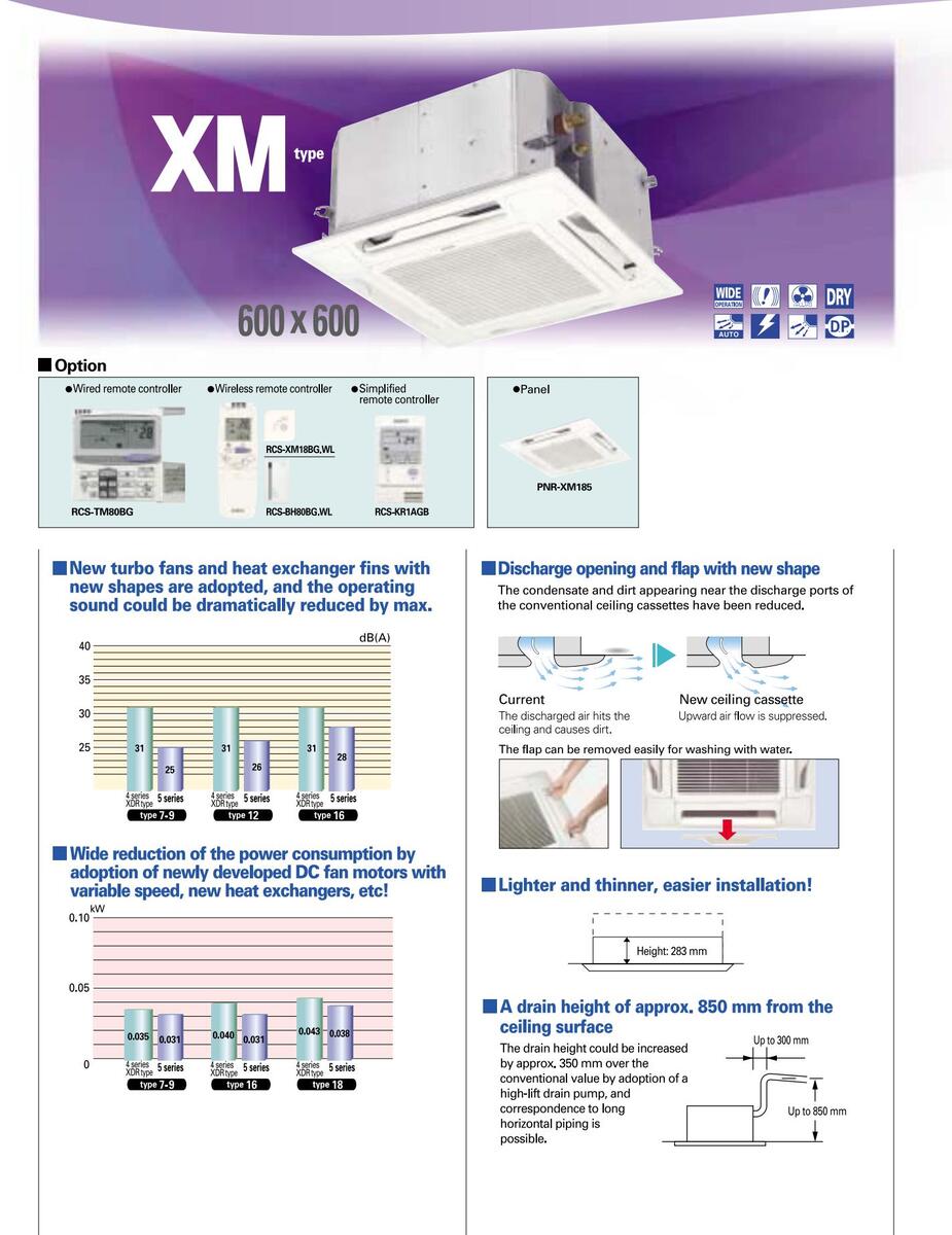
XM type (600 x 600)
Semi-Concealed Cassette |
-XM075XH | SPW-XM095> | КН | SPW-XM125XH | S | SPW-XM165XH | SPW-XM18 | ISXH | ||||
| 4-Way Air Discharge | SPW | PNR-XM185 PNR-XM185 SPW-X075XH SPW-X095XH Basel Sector | SPW-X125XH | , c | SPW-X165XH | SPW-X185 | кн | |||||
| INE-UP |
Semi-Concealed Cassette
4-Way Air Discharge |
XD484GHAB | PNR-XD484G | НАВ | PNR-XD484GHAB | F | NR-XD484GHAB | PNR-XD484 | ||||
|
Semi-Concealed Cassette
4-Way Air Discharge |
Panel
PNR |
SPW-XMR74EXH56B SPW-XMR94EXH56B SP
Panel PNR-XM184EHA PNR-XM184EHA P |
SPW-XMK124EXH56B SF
Panel PNR-XM184EHA Pt |
PNR-XM184EHA |
Panel
PNR-XM18 |
4EHA | ||||||
|
SR type
Semi-Concealed Cassette 2-Way Air Discharge |
SPW
Panel PNR |
-SR74GXH56B
S124GHB |
SPW-SR94GX
Panel PNR-S124GH |
KH56B
B |
SPW-SR124GXH56B SPanel
PNR-S124GHB |
SPW-SR164GXH56B
Panel PNR-S124GHB |
SPW-SR18
Panel PNR-S1240 |
4GXH56B
GHB |
||||
|
ADR type
Semi-Concealed Cassette 1-Way Air Discharge |
SPW
Panel PNR |
-ADR74GXH56B
AD124GHB |
SPW-ADR940
Panel PNR-AD124G |
GXH56B
HB |
SPW-ADR124GXH
Panel PNR-AD124GHB |
56B | ||||||
|
LDR type
Semi-Concealed Slim Cassette |
SPW-LDR94G
Panel PNR-LD254G |
XH56B
HAB |
SPW-LDR124GXH
Panel PNR-LD254GHAB |
i6B S |
SPW-LDR164GXH56B
Panel PNR-LD254GHAB |
SPW-LDR1
Panel PNR-LD254 |
84GXH56B
IGHAB |
|||||
|
U type
Concealed Duct |
000 9 | SPW | -U075XH | SPW-U095XH | 1 | SPW-U125XH | 5 | SPW-U165XH | SPW-U185 | KH | ||
| I S |
UR
type
Concealed-Rectangle Duct |
ctangle Duct | SPW-U075SXHT SPW-U095SXI | нт | SPW-U125SXHT | S | SPW-U165SXHT | SPW-U185 | SXHT | |||
|
US
type
Concealed Duct |
US type
Concealed Duct |
SPW-US075XH SPW-US095XH | н | SPW-US125XH | SPW-US165XH | SPW-US18 | 5XH | |||||
| 5 |
FUR type
Roor/Ceiling Slim Concealed Duct |
SPW | SPW-FUR74EXH56B SPW | SPW-FUR94EXH56B SPV | SPW-FUR124EXH56B | SPW-FUR1 | SPW-FUR184EXH56B | |||||
|
UMR type
Concealed Duct |
UMR type
Concealed Duct |
SPW-UMR74EXH56B SPW-UMR94EXH56B | EXH56B | SPW-UMR124EXH56B S | SPW-UMR164EXH56B | SPW-UMR | SPW-UMR184EXH56B | |||||
| 00 |
DR type 25-48 t
Concealed Duct High-Static Pressure |
ype
76,96 t |
уре | |||||||||
|
T type
Ceiling-Mounted Units |
SPW-T125XH | ŝ | SPW-T165XH | SPW-T185) | (H | |||||||
|
FTR type
Floor/Ceiling Mounted Units |
THE REAL | SPW | -FTR74EXH56B | SPW-FTR94E | XH56B | SPW-FTR124EXH5 | 6B S | SPW-FTR164EXH56B | SPW-FTR1 | 34EXH56B | ||
|
K type
Wall Mounted Units |
SPW | -K075XH | SPW-K095XH | SPW-K125XH | ||||||||
|
KR type
Wall-Mounted Units |
SPW | -KR74GXH56B | SPW-KR94GX | KH56B | SPW-KR124GXH56 | iB S | SPW-KR164GXH56B | SPW-KR18 | 4GXH56B | |||
|
FMR type
Concealed Floor Standing Unit |
s | SPW | -FMR74GXH56B | SPW-FMR940 | GXH56B | SPW-FMR124GXH | 56B S | SPW-FMR164GXH56B | SPW-FMR1 | 84GXH56B | ||
|
FR type
Floor Standing Units |
- | SPW | -FR74GXH56B | SPW-FR94GX | H56B | SPW-FR124GXH56 | B | SPW-FR164GXH56B | SPW-FR184 | IGXH56B | ||
|
GU type
Total Heat Exchanger with DX |
coil | SPW-GU055X | Ή | S | SPW-GU075XH | SPW-GU10 | 5XH | |||||
| F | Wired remote contro | oller | all indo or | units | XM type | X | Wireless remot |
te controll
XMR , S |
er
R,FTR type |
ADR, T, LDR ty | ре | |
| CONT |
|---|
| Wined nemete controller | Wireless remo | ote controller | |||
|---|---|---|---|---|---|
| wired remote controller | For all indoor units | XM type | X type | XMR, SR,FTR type | ADR, T, LDR |
| RCS-TM80BG | RCS-BH80BG.WL | RCS-XM18BG.WL | RCS-SH80BG.WL | RCS-SS80BG WL | RCS-TRP80B0 |
| · | |||||
| 行建立利用 | BH80BG.WL |
RCS-
BH80BG.WL |
RCS-
BH80BG.WL |
RCS-
BH80BG.WL |
RC BH |
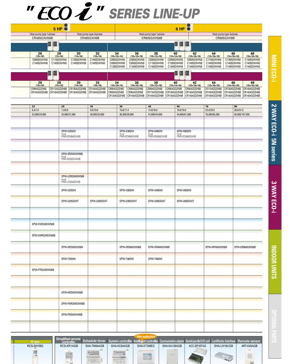
MINI ECO 1 MULTI SYSTEM
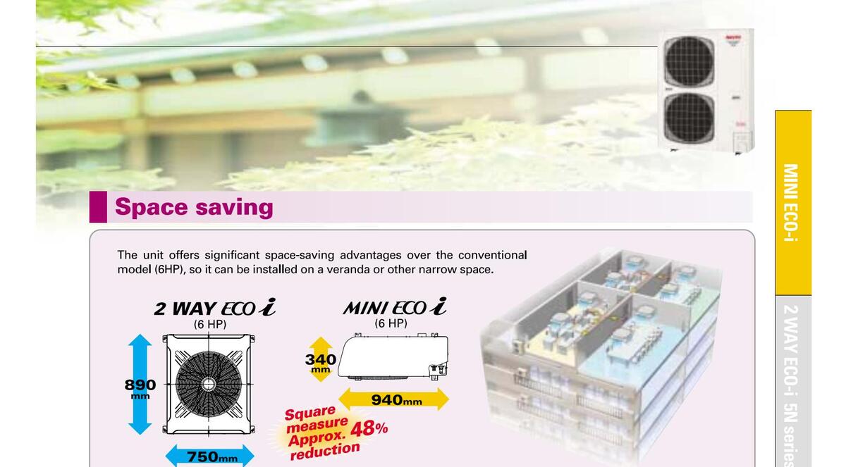
Newly developed "MINI satisfy a wider variety of
More
Efficiency
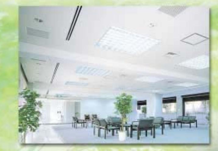
The MINI ECO-i has been developed as a higher-efficiency product that will appeal to a broader range of users. It's ideal for small offices and shops, and combined with the ECO Family Series, it can create a system that will satisfy any building owner.
Installation available even in narrow space
More Selectable Selectable for designers

MINI ECO Z MULTI SYSTEM

More excellent energy saving
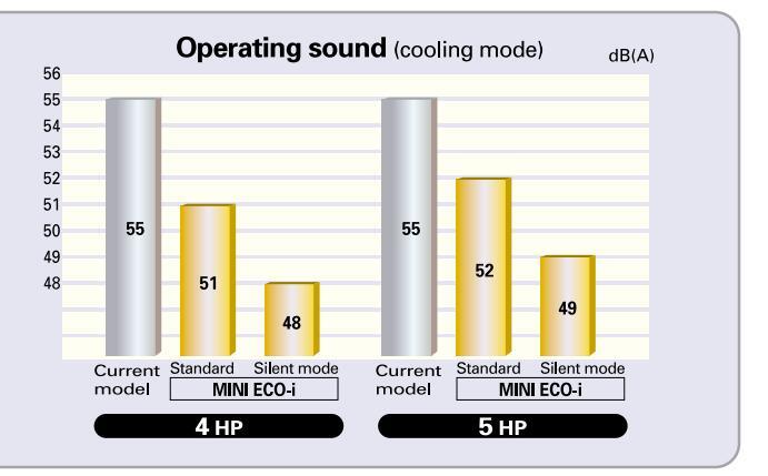
Low-operating sound design in the top class of the industry
The DC Inverter Air Conditioner uses a twin rotary compressor. Compared to the conventional single cylinder type, the twin rotary compressor dramatically reduces vibration and noise during operation, thus ensuring quiet operation.
* The rated capacity cannot be performed in silent mode.
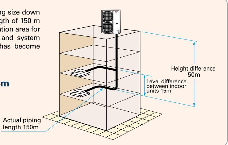
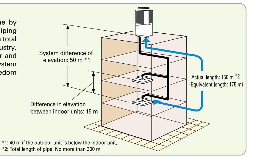
Correspondence to long piping
The reduction in the refrigerant volume by piping size down has extended the piping length to an actual length of 150 m and a total length of 200 m. The possible installation area for indoor and outdoor units has been widened and system deployment with a high degree of freedom has become possible.
Actual piping length 70m ⇒150m Equivalent piping length 120m ⇒175m Total piping length 150m ⇒ 200m
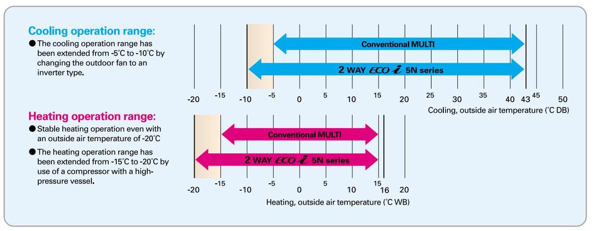
Extended operating range

Increased max. number of connectable indoor units

MINI ECO 1 MULTI SYSTEM

Outdoor unit specifications
| НР | 4 | ļ | ō | 6 | 5 | |||||||
|---|---|---|---|---|---|---|---|---|---|---|---|---|
| Heat pu | mp type | Heat pu | mp type | Heat pu | mp type | |||||||
| Wodel n | ame (SPW-) | CR365GXH56B CR365GXH8B | CR485GXH56B | CR485GXH8B | CR605GXH56B | CR605GXH8B | ||||||
| Power s | upply |
220/230/240V-
1 phase/50, 60Hz |
380/400/415V-
3 phase/50, 60Hz |
220/230/240V-
1 phase/50, 60Hz |
380/400/415V-
3 phase/50, 60Hz |
220/230/240V- 380/400/415V-
1 phase/50, 60Hz 3 phase/50, 60H |
||||||
| (kW) | 11 | .2 | 14 | .0 | 15.5 | |||||||
| Capacity | (BTU/h) | 38, | 200 | 47, | 300 | 52,900 | ||||||
| Heating (kW) | 12 | 2.5 | 16 | .0 | 17 | .6 | ||||||
| (BTU/h) | 42, | 700 | 54, | 500 | 60, | 000 | ||||||
| COR | Cooling (W/W) | 4. | 06 | 3.0 | 66 | 3.: | 39 | |||||
| Heating (W/ | 4. | 34 | 4. | 10 | 3.8 | 84 | ||||||
| Dimensio | on (H×W×D) (mm) | 1,230×940×340 | ||||||||||
| Net wei | ght (kg) | 10 | )4 | |||||||||
| Running amperes (A) | 14.8/14.1/13.5 | 4.56/4.34/4.18 | 20.5/19.6/18.8 | 6.20/6.02/5.80 | 24.4/23.4/22.4 | 7.40/7.18/6.92 | ||||||
| ratin | Power input (kW) | 2. | 76 | 3.8 | 33 | 4. | 57 | |||||
|
trical
puttor |
Running amperes (A) | 15.4/14.7/14.1 4.76/4.52/4.36 | 20.8/19.9/19.1 | 6.31/6.13/5.90 | 24.5/23.4/22.5 | 7.41/7.19/6.93 | ||||||
| Power input (kW) | 2. | 88 | 3.1 | 90 | 4.58 | |||||||
| Color (mu | nsell color chart) | |||||||||||
| Air circul | lation (m³/min) | 10 | 00 | 10 | 00 | 100 | ||||||
|
Refrigeran
shipment |
nt amount at (kg) | 3 | .5 | 3. | 5 | 3.5 | ||||||
| Piping |
Gas pipe
(Flare) (mm) |
ø15.8 | 8 | ø19.( | )5 * 1 | |||||||
| connection | s Liquid pipe (mm) | ø9. | 52 | |||||||||
|
Ambient ten
operating ra |
nperature
nge |
Cooling: - | 10°C DB~+ 43°C DB, | heating: -20°C WB ~ | +15°C WB | |||||||
| Maximum connectab |
number of
ble indoor units |
6 | 5 | } | 9 | |||||||
| Pressure | Normal mode dB(A) | 5 | 1 | 5 | 1 | 5: | 2 | |||||
| sound | Silent mode dB(A) | 4 | 8 | 4 | 8 | 49 | 9 | |||||
| Power sound | Normal mode dB(A) | 6 | 7 | 6 | 7 | 6 | 8 | |||||
* The values for performance and electric characteristics apply under the following test conditions.
At the time of cooling: Indoor suction air temperature 27°C DB, 19°C WB, outdoor suction air temperature 35°C DB At the time of heating: Indoor suction air temperature 20°C DB, outdoor suction air temperature 7°C DB, 6°C WB
* The operating sound has been r * The operating sound has been measured in an anechoic chamber, and it is the value one meter in front of the outdoor unit at a height of 1.5 m. With actual installation, the indication value normally differs widely according to the surrounding noise and reverberations.
*1; Tube discharge assy supplied with outdoor unit
■ Optional parts
| APB-P160BG 22.4 kW or less For indoor unit | Model name | Cooling capacity after distribution | Remarks |
|---|---|---|---|
| APR-P160BG | 22.4 kW or less | For indoor unit |
| Valve connecting | g tube size (mm) | Indoor unit where used | |
|---|---|---|---|
| Model No. | Gas tube | Liquid tube | Total capacity of indoor units after the valve |
| BV-RXP160AGB | 15.88 | 9.52 | 16.0 kW or less |
| BV-RXP56AGB | 12.7 | 6.35 | 5.6 kW or less |
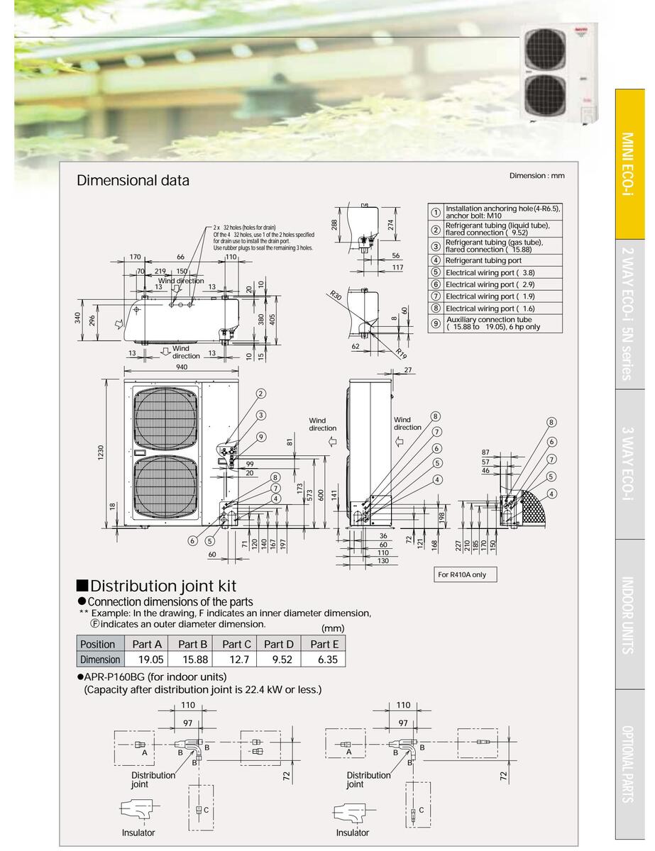
MINI ECO 2 MULTI SYSTEM


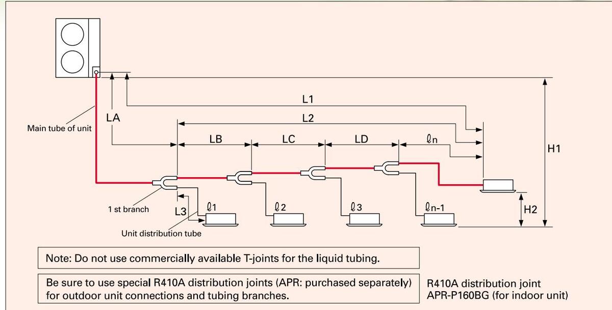
Ranges that apply to refrigerant tubing lengths and to differences in installation heights
| Items | Marks | Contents | Length (m) | |
|---|---|---|---|---|
| 1.1 | Max, mining longth | Actual piping length | ≦150 | |
| Allowable | LI | wax. piping length | Equivalent piping length | ≦175 |
| tubing length | ∆L (L2 —L3) | Difference between the ma | ≦40 | |
| l1, l2 ~ln | Max. length of each distribu | ≦30 | ||
| Q 1 +Q 2 +~Q n-1 +L1 | Total max. tubing length inc | ≦200 | ||
| LI1 | When outdoor unit is installed | ≦50 | ||
|
Allowable
elevation |
When outdoor unit is installed | ≦40 | ||
| difference | H2 | Max. difference between in | door units | ≦15 |
L = Length, H = Height
Main tubing size (Ι Δ)
| kW | 11.2 | 15.5 | |||||||||
|---|---|---|---|---|---|---|---|---|---|---|---|
| System horsepower | 4 | 6 | |||||||||
| Gas tubing (mm) | ø1 | ø19.05 | |||||||||
| Liquid tubing (mm) | ø9 . 52 | ||||||||||
System limitations
| Outdoor units (Type) | 365 | 485 | 605 | ||
|---|---|---|---|---|---|
| Number of max. connectable indoor units | 6 | 8 | 9 | ||
| Max. allowable indoor/ outdoor capacity ratio | io 50-130% | ||||
Main tubing size after distribution (LB, LC...)
| Total capacity | Below kW | 7.1 (2.5 hp) | 11.2 (4 hp) 14.0 (5 hp) | 15.5 (6 hp) | ||
|---|---|---|---|---|---|---|
| after distribution | Over kW | — | 7.1 (2.5 hp) | |||
| Tubing size | Gas tubing (mm) | ø12 . 7 | ø15 . 88 | Unit | ||
| Tubing size | Liquid tubing (mm) | ø9 . 52 | ø9 . 52 | hp = | ||
Note: In case the total capacity of connected indoor units exceeds the total capacity of the outdoor units, select the main tubing size for the total capacity of the outdoor units.
Indoor unit tubing connection (l1, l2 ... ln-1)
| bing c | ||||||||||
|---|---|---|---|---|---|---|---|---|---|---|
| Indoor unit type | 7 | 9 | 12 | 16 | 18 | 25 | 36 | 48 | 60 | |
| Gas tubing (mm) | ø12.7 | ø15.88 | ||||||||
| Liquid tubing (mm) | ø6.35 | ø9.52 | ||||||||

Large-capacity multi systems from Sanyo!
with use of R410A with advanced technology
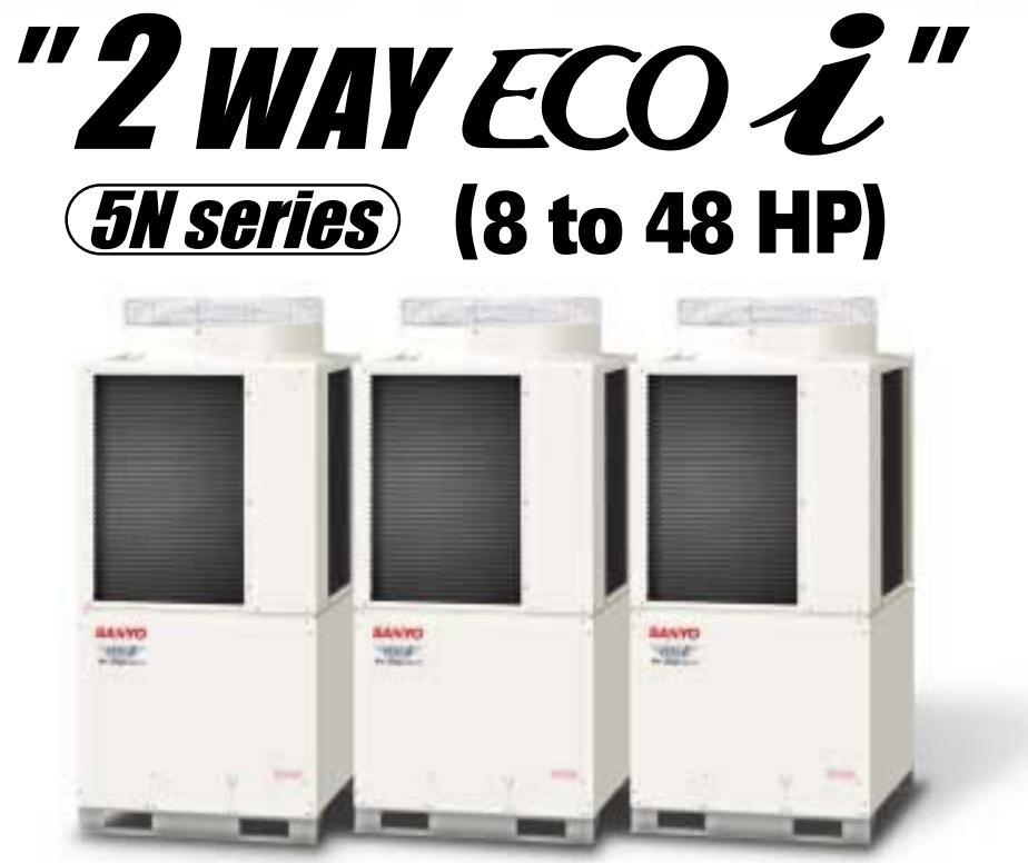
2 WAY ECO-i 5N serie:
High-efficiency large-capacity multi system
A high-performance multi system with excellent energy savings and work execution characteristics for buildings.
High performance and various options contribute to the creation of comfortable space meeting various needs.
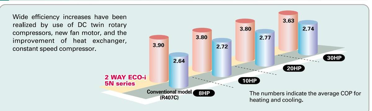
- Top class COP=3.90 (In case of 8 HP average)
- Twin rotary DC Inverter compressor
- DC FAN motor
- Space saving outdoor unit New 14 & 16HP
- New heat exchanger
- All model is the same size for easier installation.


More excellent energy saving
Line-up expansion
The 2 WAY ECO-i 5N series has all five DC inverter outdoor units from 8 HP to 16 HP as the basic models, and by combination of up to three units, an air-conditioning capacity 8 HP to 48 HP can be set according to the user needs.
| НР | 8 | 10 | 12 | 14 | 16 | 18 | 20 | 22 | 24 | 26 | 28 |
|---|---|---|---|---|---|---|---|---|---|---|---|
| 2 WAY ECO-i 5N series | Ø | 0 | O | O | O | 0 | O | O | O | O | Ø |
| Inverter unit | 8 | 10 | 12 | 14 | 16 | 10 | 10 | 12 | 14 | 16 | 16 |
| 8 | 10 | 10 | 10 | 10 | 12 | ||||||
| I | |||||||||||
| HP | 30 | 32 | 34 | 36 | 38 | 40 | 42 | 44 | 46 | 48 | |
| 2 WAY ECO-i 5N series | O | 0 | 0 | O | 0 | 0 | O | 0 | 0 | O | |
| 16 | 16 | 14 | 16 | 16 | 16 | 16 | 16 | 16 | 16 | ||
| Inverter unit | 14 | 16 | 10 | 10 | 12 | 14 | 16 | 16 | 16 | 16 | |
| 10 | 10 | 10 | 10 | 10 | 12 | 14 | 16 |
Extended operating range
capacity multi adopts R410A refrigerant
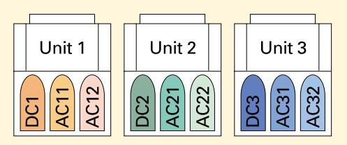
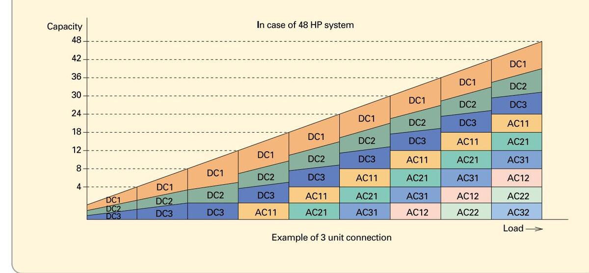
Realization of smooth capacity control from 0.8HP to 48HP
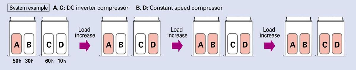
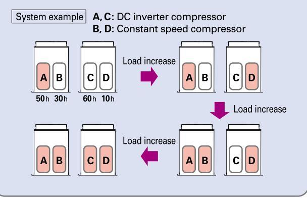
Capacity control is possible smoothly with a DC inverter compressor. The lower graph shows the image of the operating combination of compressors in case of 48 HP system. In actual operation, the combination will be changed by operating condition, operating time amount, priority of compressor and so on.
| Comp. HP | Unit 1 (main) | Unit 2 (sub 1) | Unit 3 (sub 2) |
|---|---|---|---|
| DC comp. | 4.0 | 4.0 | 4.0 |
| AC1 comp. | 6.0 | 6.0 | 6.0 |
| AC2 comp. | 6.0 | 6.0 | 6.0 |
2 WAY ECO-i 5N series
*48HP = SPW-C1405DXH8 x 3

High efficiency and large
Smallest installation space in the industry! Further reduction of the operating sound

capacity multi adopts R410A refrigerant
Extended compressor life by uniform compressor operation times
The total operation time of the compressors is monitored by a microcomputer, so that there is no unbalance for the operation times of all compressors in the same refrigerant system, and compressors with a shorter operation time are operated with preference.
Reduction of the piping cost and construction labor by smaller piping size
By adoption of R410A with low pressure loss, it was possible to reduce the piping sizes for gas pipes and liquid pipes. This makes it possible to aim for reduced piping space, improved workability at the site, and reduction of the piping material costs.
Example: In case of 10 HP
(mm Conventional model 2WAY ECO-i 5N series Gas pipe Liquid pipe Gas pipe Liquid pipe 8 25.4 12.7 19.05 9.52 10 28.58 12.7 22.22 9.52
2 WAY ECO-i 5N serie:
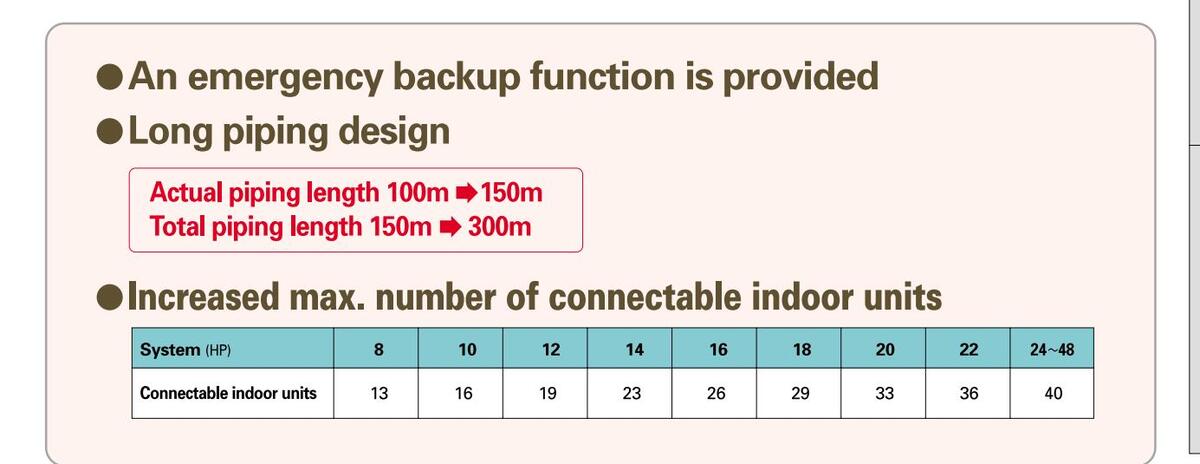
Correspondence to long piping in the top class of the industry
The reduction in the refrigerant volume by piping size down has extended the piping length to an actual length of 150 m and a total length of 300 m, the top class in the industry. The possible installation area for indoor and outdoor units has been widened and system deployment with a high degree of freedom has become possible.
Actual piping length: 150m Equivalent piping length: 175m Total piping length: 300m

Outdoor unit specifications,
Outdoor unit specifications
| Appearance | |||||||||||
|---|---|---|---|---|---|---|---|---|---|---|---|
| н | Р | 8 | 10 | 12 | 14 | 16 | |||||
| Model name (SPW-) | PW-) | C0705DXHN8 | C0905DXHN8 | C1155DXHN8 | C1305DXHN8 | C1405DXHN8 | |||||
| Power supply | 380/400/415V-3 phase/50Hz | ||||||||||
| 22.4 | 28.0 | 33.5 | 40.0 | 45.0 | |||||||
| G | anacity | ocoming | (BTU/h) | 76,400 | 95,500 | 114,300 | 136,500 | 153,600 | |||
| ľ | apaonty | Heating | (kW) | 25.0 | 31.5 | 37.5 | 45.0 | 50.0 | |||
| neuting | (BTU/h) | 85,300 | 107,500 | 128,000 | 153,600 | 170,600 | |||||
| СОР | Cooling | (W/W) | 3.74 | 3.54 | 3.50 | 3.45 | 3.38 | ||||
| Heating | (W/W) | 4.05 | 4.06 | 3.91 | 3.91 | 3.79 | |||||
| Dimensions(H×W×D) (mm) | (mm) | 1 | ,887 x 890 x 890 (+60 | ) | |||||||
| Net weight (kg) | (kg) | 245 | 295 | 295 | 345 | 345 | |||||
| Cooling | Running ampe | eres (A) | 10.1/9.6/9.3 | 12.9/12.3/11.8 | 15.6/14.9/14.3 | 19.6/18.6/17.9 | 22.5/21.3/20.6 | ||||
| ating | cooning | Power input (kW) | 5.99 | 7.90 | 9.58 | 11.6 | 13.3 | ||||
| icalr | Heating | Running ampe | eres (A) | 10.4/9.9/9.5 | 12.7/12.0/11.6 | 15.7/14.9/14.3 | 19.4/18.5/17.8 | 22.3/21.2/20.4 | |||
| Electr | nearing | Power input | (kW) | 6.17 | 7.75 | 9.60 | 11.5 | 13.2 | |||
| Starting a | mperes | (A) | 1/1/1 | 59/62/64 | 66/69/72 | 68/71/73 | 78/80/82 | ||||
| A | ir circulat | ion | (m³/min) | 150 | 160 | 180 | 200 | 220 | |||
| R | efrigerant a | amount at ship | ment (kg) | 11.8 | |||||||
| Gas pipe | (mm) | ø19.05 | ø22.22 | ø25.4 | ø25.4 | ø28.58 | |||||
|
Pi
Co |
ping
onnectior |
Liquid pipe | (mm) | ø9.52 | ø9.52 | ø12.7 | ø12.7 | ø12.7 | |||
| Balance pip | e (mm) | ø6.35 | ø6.35 | ø6.35 | ø6.35 | ø6.35 | |||||
| An | nbient temp | erature operating | ı range | Cooling/dry: -10°C | ~+ 43°C (DB), Heating: | -20°C ~+15°C (WB) | |||||
| Pre | ssure sound | Normal mod | de dB(A) | 54.5 | 55.0 | 56.0 | 61.0 | 62.0 | |||
| Silent mode | edB(A) | 51.5 | 52.0 | 53.0 | 58.0 | 59.0 | |||||
| Po | wer sound | Normal mod | de dB(A) | 65.5 | 66.5 | 67.5 | 71.5 | 72.0 | |||
* The values for performance and electric characteristics apply under the following test conditions.
Data subject to change without notice.
At the time of cooling: Indoor suction air temperature 27°C DB, 19°C WB, outdoor suction air temperature 35°C DB At the time of heating: Indoor suction air temperature 20°C DB, outdoor suction air temperature 7°C DB, 6°C WB
* The operating sound has been measured in an anechoic chamber, and it is the value one meter in front of the outdoor unit at a height of 1.5 m. With actual installation, the indication value normally differs widely according to the surrounding noise and reverberations.


OUTDOOR UNITS SPECIFICATIONS
| Appearanc | ce | ||||||||||||
|---|---|---|---|---|---|---|---|---|---|---|---|---|---|
| НР | 8 | 10 | 12 | 14 | 16 | 18 | 20 | 22 | 24 | ||||
| Model nam | ne (SF | 'W- ) | C0705DXHN8 | C0905DXHN8 | C1155DXHN8 | C1305DXHN8 | C1405DXHN8 |
C0905DXHN8
C0705DXHN8 |
C0905DXHN8
C0905DXHN8 |
C1155DXHN8
C0905DXHN8 |
C1305DXHN8
C0905DXHN8 |
||
| Power sup | ply |
380/400/415V-
3phase/50, 60Hz |
380/400/415V | -3phase/50Hz | |||||||||
| Coolin | (kW) | 22.4 | 28.0 | 33.5 | 40.0 | 45.0 | 50.4 | 56.0 | 61.5 | 68.0 | |||
| Capacity | 9 | (BTU/h) | 76,400 | 95,500 | 114,300 | 136,500 | 153,600 | 172,000 | 191,100 | 209,900 | 232,000 | ||
| Capacity | Heatin | a | (kW) | 25.0 | 31.5 | 37.5 | 45.0 | 50.0 | 56.5 | 63.0 | 69.0 | 76.5 | |
| meatin | 'Y | (BTU/h) | 85,300 | 107,500 | 128,000 | 153,600 | 170,600 | 192,800 | 215,000 | 235,500 | 261,000 | ||
| COP | Coolin | g | (W/W) | 3.74 | 3.54 | 3.50 | 3.45 | 3.38 | 3.63 | 3.54 | 3.51 | 3.49 | |
| Heatin | g | (W/W) | 4.05 | 4.06 | 3.91 | 3.91 | 3.79 | 4.06 | 4.06 | 3.97 | 3.96 | ||
| Dimensions | (HxWxD | 1 | (mm) | 1,88 | 87 x 890 x 890 | (+60) | 1,887 x 1,88 | 0 x 890 (+60) | |||||
| Net weight | (kg) | 245 | 295 | 295 | 345 | 345 | 540 | 590 | 590 | 640 | |||
| Coolin | g Running amperes | (A) | 10.1/9.6/9.3 | 12.9/12.3/11.8 | 15.6/14.9/14.3 | 19.6/18.6/17.9 | 22.5/21.3/20.6 | 23.0/21.9/21.1 | 25.8/24.6/23.6 | 28.5/27.2/26.1 | 32.5/30.9/29.7 | ||
| Electrical | Power input | (kW) | 5.99 | 7.90 | 9.58 | 11.6 | 13.3 | 13.9 | 15.8 | 17.5 | 19.5 | ||
| ratings | Heatin | g Running amperes | (A) | 10.4/9.9/9.5 | 12.7/12.0/11.6 | 15.7/14.9/14.3 | 19.4/18.5/17.8 | 22.3/21.2/20.4 | 23.1/21.9/21.1 | 25.4/24.0/23.2 | 28.4/26.9/25.9 | 32.1/30.5/29.4 | |
| Power input | (kW) | 6.17 | 7.75 | 9.60 | 11.5 | 13.2 | 13.9 | 15.5 | 17.4 | 19.3 | |||
| Air circulat | ion | (m³/min) | 150 | 160 | 180 | 200 | 220 | 150+160 | 160+160 | 160+180 | 160+200 | ||
| Refrigerant a | amount | at shipment | (kg) | 11.8 | 23 | 3.6 | |||||||
| Gas pipe | (mm) | ø19.05 | ø22.22 | ø25.4 | ø25.4 | ø28.58 | ø28.58 | ø28.58 | ø28.58 | ø28.58 | |||
| Piping conne | ctions | Liquid pipe | (mm) | ø9.52 | ø9.52 | ø12.7 | ø12.7 | ø12.7 | ø15.88 | ø15.88 | ø15.88 | ø15.88 | |
| Balance pipe | (mm) | ø6.35 | ø6.35 | ø6.35 | ø6.35 | ø6.35 | ø6.35 | ø6.35 | ø6.35 | ø6.35 | |||
| Ambient terr | nperature | operating range | Co | ooling/Dry: -10° | C~+43°C (DB), | Heating: -20°C | ~+15°C (WB) | ||||||
| Operating so | und | Normal mode | dB(A) | 54.5 | 55.0 | 56.0 | 61.0 | 62.0 | 58 | 58 | 58.5 | 62.0 | |
| - providing of | Silent mode | dB(A) | 51.5 | 52.0 | 53.0 | 58.0 | 59.0 | 55 | 55 | 55.5 | 59.0 |
Note: Rated conditions Cooling: indoor air temperature 27'C CB/19'C WB, outdoor air temperature 35'C DB Heating: indoor air temperature 20'C DB, outdoor air temperature 7'C DB/6'C WB

| 26 | 28 | 30 | 32 | 34 | 36 | 38 | 40 | 42 | 44 | 46 | 48 |
|---|---|---|---|---|---|---|---|---|---|---|---|
|
C1405DXHN8
C0905DXHN8 |
C1405DXHN8
C1155DXHN8 |
C1405DXHN8
C1305DXHN8 |
C1405DXHN8
C1405DXHN8 |
C1305DXHN8
C0905DXHN8 C0905DXHN8 |
C1405DXHN8
C0905DXHN8 C0905DXHN8 |
C1405DXHN8
C1155DXHN8 C0905DXHN8 |
C1405DXHN8
C1305DXHN8 C0905DXHN8 |
C1405DXHN8
C1405DXHN8 C0905DXHN8 |
C1405DXHN8
C1405DXHN8 C1155DXHN8 |
C1405DXHN8
C1405DXHN8 C1305DXHN8 |
C1405DXHN8
C1405DXHN8 C1405DXHN8 |
| 380/400/415\ | /-3phase/50H: | Z | |||||||||
| 73.0 | 78.5 | 85.0 | 90.0 | 96.0 | 101.0 | 107.0 | 113.0 | 118.0 | 124.0 | 130.0 | 135.0 |
| 249,100 | 267,900 | 290,000 | 307,100 | 327,600 | 344,600 | 365,100 | 385,600 | 402,700 | 423,100 | 443,600 | 460,700 |
| 81.5 | 87.5 | 95.0 | 100.0 | 108.0 | 113.0 | 119.0 | 127.0 | 132.0 | 138.0 | 145.0 | 150.0 |
| 278,100 | 298,600 | 324,200 | 341,200 | 368,500 | 385,600 | 406,100 | 433,400 | 450,400 | 470,900 | 494,800 | 511,800 |
| 3.44 | 3.43 | 3.41 | 3.38 | 3.50 | 3.47 | 3.47 | 3.45 | 3.42 | 3.43 | 3.40 | 3.38 |
| 3.88 | 3.84 | 3.85 | 3.79 | 4.00 | 3.94 | 3.89 | 3.91 | 3.86 | 3.83 | 3.83 | 3.79 |
| 1,887 x 1,880 | x 890 (+60) | 1,887 x 2,870 | × 890 (+60) | ||||||||
|
640 |
640 | 690 | 690 | 935 | 935 | 935 | 985 | 985 | 985 | 1,035 | 1,035 |
| 35.4/33.6/32.4 | 38.1/36.2/34.9 | 42.1/39.9/38.5 | 45.0/42.6/41.2 | 45.4/43.2/41.5 | 48.3/45.9/44.2 | 51.0/48.5/46.7 | 55.0/52.2/50.3 | 57.9/54.9/53.0 | 60.6/57.5/55.5 | 64.6/61.2/59.1 | 67.5/63.9/61.8 |
| 21.2 | 22.9 | 24.9 | 26.6 | 27.4 | 29.1 | 30.8 | 32.8 | 34.5 | 36.2 | 38.2 | 39.9 |
| 35.0/33.2/32.0 | 38.0/36.1/34.7 | 41.7/39.7/38.2 | 44.6/42.4/40.8 | 44.8/42.5/41.0 | 47.7/45.2/43.6 | 50.7/48.1/46.3 | 54.4/51.7/49.8 | 57.3/54.4/52.4 | 60.3/57.3/55.1 | 64.0/60.9/58.6 | 66.9/63.6/61.2 |
|
21.0 |
22.8 | 24.7 | 26.4 | 27.0 | 28.7 | 30.6 | 32.5 | 34.2 | 36.0 | 37.9 | 39.6 |
|
160+220 |
180+220 | 200+220 | 220+220 | 160+160+200 | 160+160+220 | 160+180+220 | 160+200+220 | 160+220+220 | 180+220+220 | 200+220+220 | 220+220+220 |
| 23 | .6 | 35 | .4 | ||||||||
| ø31.75 | ø31.75 | ø31.75 | ø31.75 | ø31.75 | ø38.1 | ø38.1 | ø38.1 | ø38.1 | ø38.1 | ø38.1 | ø38.1 |
| ø19.05 | ø19.05 | ø19.05 | ø19.05 | ø19.05 | ø19.05 | ø19.05 | ø19.05 | ø19.05 | ø19.05 | ø19.05 | ø19.05 |
| ø6.35 | ø6.35 | ø6.35 | ø6.35 | ø6.35 | ø6.35 | ø6.35 | ø6.35 | ø6.35 | ø6.35 | ø6.35 | ø6.35 |
|
|
Cooling/Dry: -1 | 0°C~+43°C (DE | 8), Heating: -20 | °C~+15°C (WB) | |||||||
| 63.0 | 63.0 | 64.5 | 65.0 | 63.0 | 63.5 | 63.5 | 65.0 | 65.5 | 65.5 | 66.5 | 67.0 |
| 60.0 | 60.0 | 61.5 | 62.0 | 60.0 | 60.5 | 60.5 | 62.0 | 62.5 | 62.5 | 63.5 | 64.0 |
Data subject to change without notice
The state of the s
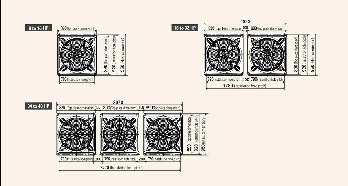
2 WAY ECO-i 5N series
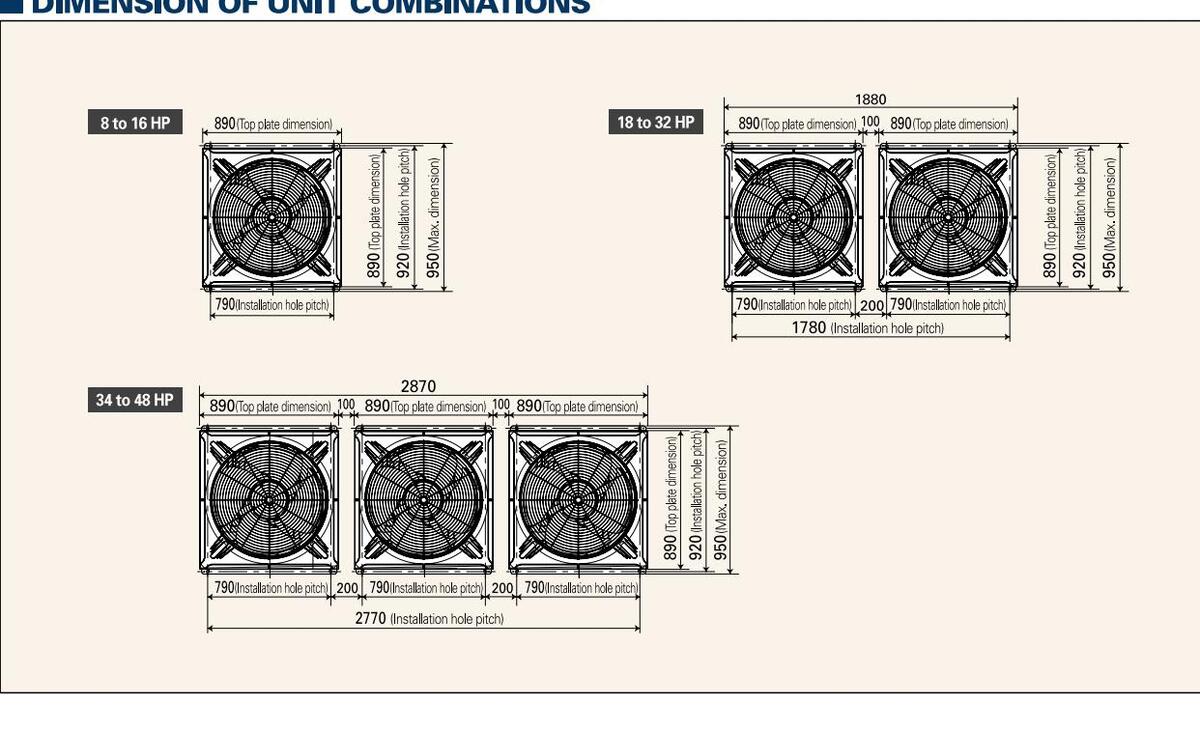
DIMENSION OF UNIT COMBINATIONS
Downloaded from www.Manualslib.com manuals search engine


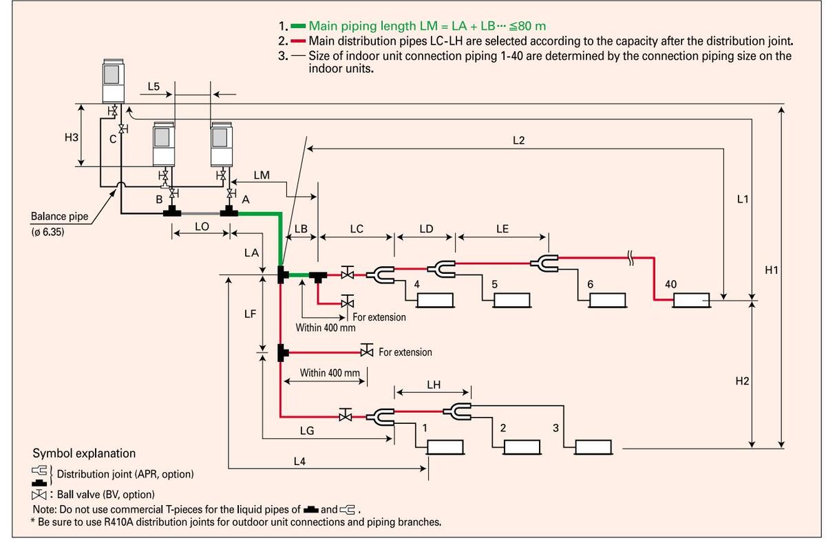
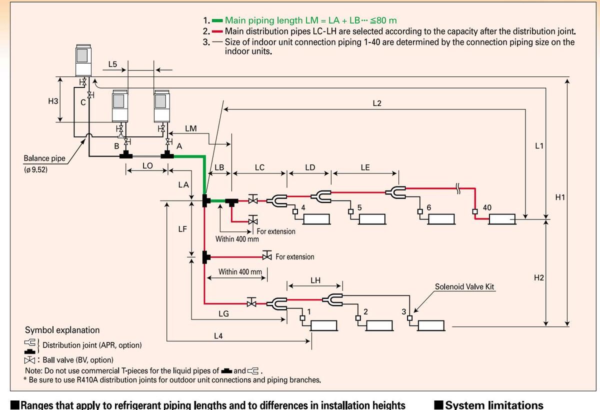
Piping design
Ranges that apply to refrigerant piping lengths and to differences in installation heights
| Items | Marks | Contents | Length (m) | |
| 11 | May piping length | Actual piping length | ≦150 | |
| wax, piping length | Equivalent piping length | ≦175 | ||
| Allowable | ∆L (L2 —L4) | Difference between the max. I the No.1 distribution joint | ength and the min. length from | ≦40 |
| piping length | LM | Max. length of main piping | (at max. diameter) | ≦80 |
| 1, 2~40 | Max. length of each distrib | ution | ≦30 | |
|
L1+1+2+∼40
+A+B+LF+LG+LH |
Total max. piping length ind
distribution (only narrow tu |
cluding length of each
Ibing) |
≦300 | |
| L5 | Distance between PC and A | AD unit | ≦10 | |
| 111 | When outdoor unit is installed | higher than indoor unit | ≦50 | |
| Allowable | When outdoor unit is installed | lower than indoor unit | ≦40 | |
| difference | H2 | Max. difference between in | door units | ≦15 |
| H3 | Max. difference between o | utdoor units | ≦4 |
Note 1: The outdoor connection main piping (LO part) depends on the total capacity of the outdoor units connected to the end.
Note 2: When the main piping length (L1) (equivalent length) exceeds 90 m, increase the size of both the gas and liquid main piping (LM) by 1 step.
Distribution joint kits
| Remarks | Model name |
Cooling capacity
after distribution |
|---|---|---|
| For outdoor upit | 1. APR-CHP680BG | 68.0 kW or less |
| For outdoor unit | 2. APR-CHP1350BG | 135.0 kW or less |
| 3. APR-P160BG | 22.4 kW or less | |
| For indoor unit | 4. APR-P680BG | 68.0 kW or less |
| 5. APR-P1350BG | 135.0 kW or less |
System limitations
| Max. number of combined outdoor units | 3 |
|
Max. HP of combined
outdoor units |
135 kW (48 hp) |
|
Max. number of connectable
indoor units |
40 |
| Indoor/outdoor unit capacity ratio | 50-130% |
Additional refrigerant charge
| 0 0 | |
|---|---|
| Liquid piping size | Amount of refrigerant charge/m (g/m) |
| ø6.35 | 26 |
| ø9.52 | 56 |
| ø12.7 | 128 |
| ø15.88 | 185 |
| ø19.05 | 259 |
| ø22 . 22 | 366 |
Refrigerant piping
| - | |||
|---|---|---|---|
| Piping s | ize (mm) | ||
| 0 mat | terial | 1/2 H, H | material |
| Outer diameter | Wall thickness | Outer diameter | Wall thickness |
| ø 6.35 | t 0.8 | ø 25.4 | t 1.0 |
| ø 9.52 | t 0.8 | ø 28.58 | t 1.0 |
| ø 12.7 | t 0.8 | ø 31.75 | t 1.1 |
| ø 15.88 | t 1.0 | ø 38.1 | t 1.15 |
| ø 19.05 | t 1.0 | ø 41.28 | t 1.20 |
| ø 22.22 | t 1.15 | ||
Note: When pipe bending is to be performed, the bending radius shall be at least 4 times the outer diameter. Also, take sufficient care to prevent pipe collapse and damage at the time of bending.

Main pipe sizes (LA)
| HP | 8 | 10 | 12 | 14 | 16 | 18 | 20 | 22 | 24 | 26 | 28 | 30 | 32 | 34 | 36 | 38 | 40 | 42 | 44 | 46 | 48 |
|---|---|---|---|---|---|---|---|---|---|---|---|---|---|---|---|---|---|---|---|---|---|
| Combined outdoor units | 8 | 10 | 12 | 14 | 16 |
10
8 |
12
8 |
14
8 |
16
8 |
14
12 |
16
12 |
16
14 |
16
16 |
16
10 8 |
16
12 8 |
16
14 8 |
16
16 8 |
16
14 12 |
16
16 12 |
16
16 14 |
16
16 16 |
| Gas pipe (mm) | ø19 . 05 | ø22.22 | ø2 | 5.4 | ø28.58 | ø31.75 | ø38.1 | ||||||||||||||
| Liquid pipe (mm) | ø9. | 52 | ø12.7 | ø15 | 5.88 | ø19 | 0.05 |
Note 1: When future expansion is planned, select the piping diameter according to the total HP after expansion. Note 2: The balance piping size is ø 6.35. Note 3: Max. length for the main pipe (LM); when the length exceeds 50 m, the size of the Gas pipe shall be increased by one size from the main pipe size up to 50 m. (For lengths in excess of 50 m, select from the above main pipes size table.)
Main piping size between outdoor units (LO)
Select the piping size between outdoor units according to the main pipe size (LA) of the above table.
Main piping size after distribution (LB, LC, ...)
| Total capacity | Below kW | 7.1 | 16.0 | 22.5 | 30.0 | 42.0 | 52.4 | 70.0 | 98.0 | — | |
|---|---|---|---|---|---|---|---|---|---|---|---|
| after distribution | Over kW | _ | 7.1 | 16.0 | 22.5 | 30.0 | 42.0 | 52.4 | 70.0 | 98.0 | |
| Pining size | Gas pipe | (mm) | ø 12.7 | ø 15.88 | ø 19.05 | ø 22.22 | ø 25.4 | ø 28 | 3.58 | ø 31.75 | ø 38.1 |
| 1 101119 3126 | Liquid pipe | (mm) | ø 9 | .52 | ø 1 | 2.7 | ø 15.88 | ø 19 | 9.05 |
Note 1: The outdoor unit connection main pipe (LO part) depends on the total capacity of the outdoor units connected to the end. Select the Note 1: The outdoor unit connection main pipe (LC) party depends on the total capacity of the outdoor units connected to the end. Select the piping size from the table for the main pipe size after distribution. Note 2: When the total capacity of the indoor units connected to the end differs from the total capacity of the outdoor units, select the main pipe size according to the total capacity of the outdoor units. (Especially the main pipe part of LA, LB, LF, etc.)
Indoor unit connection piping (1 to 40)
| Indoor unit typ | be | 7 type | 9 type | 12 type | 16 type | 18 type | 25 type | 36 type | 48 type | 60 type | 76 type | 96 type | |
|---|---|---|---|---|---|---|---|---|---|---|---|---|---|
| Equivalent HP | 0.8 | 1 | 1.3 | 1.6 | 2 | 2.5 | 4 | 5 | 6 | 8 | 10 | ||
|
Piping between
solenoid valve kit |
Gas pipe | (mm) | ø 12.7 | ø 1! | 5.88 | ø 19.05 | ø 22.22 | ||||||
|
and indoor
connection piping Liquid pipe (mm) ø 6.35 |
ø 9. | 52 | |||||||||||

2 WAY ECO-i 5N series
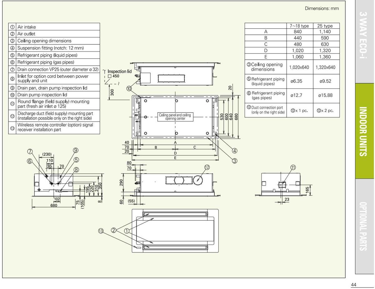
3 WAY ECO i MULTI SYSTEM
New 3 WAY ECO-i MULTI simultaneous heating
Fully-automatic simultaneous Cooling/Heating operation and heat recovery
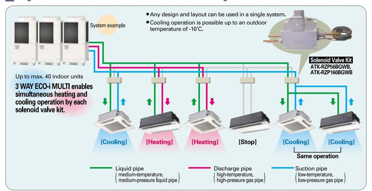
The advanced technology of 3 WAY ECO-i MULTI
The outdoor units have been unified to a body of the same size. Unification to one size and combination of five types. This permits a neat fit even when several units are installed, and space savings in the top class of the industry have been realized.
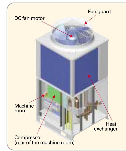
Improved operation efficiency
In addition to the development of a new DC fan motor with high output and high efficiency, the output loss has been reduced by reducing the resistance of the fan guard. This contributes widely to COP increase.
The constant-speed compressor adopts a high-performance internal high-pressure scroll
In comparison with the conventional low-pressure scroll, the oil behavior is stabilized, COP is improved, and the reliability is also improved.
Improvement of the heat exchanger
Hairpins with a diameter of 7 mm are used for the heat exchanger, and the radiation area has been increased. In addition, the air speed distribution has been improved by 4-direction suction, and the COP has also been improved.
Review of the layout of the structural parts
Noise reduction has been realized by arranging the compressor in a special machine room at the bottom.
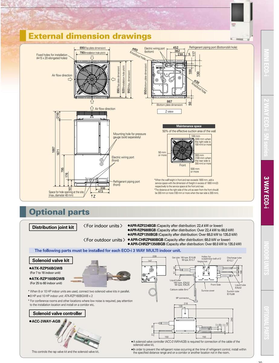
Close side-by-side installation is possible
The mounting fittings for the outdoor unit have been changed to the front and the rear, so that the units can be installed side by side with just 100 mm between units and reduction of the installation space has been realized.
Downloaded from www.Manualslib.com manuals search engine
** Compressor AC: Constant-speed compressor, DC: DC inverter compresso
3 WAY ECO 2 MULTI SYSTEM
More excellent energy saving
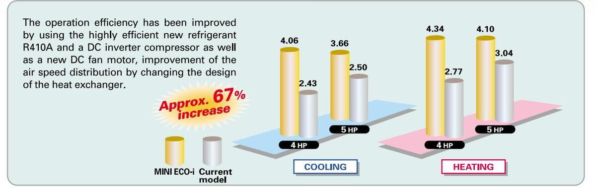
The operation efficiency has been improved by using the highly efficient new refrigerant R410A and a DC inverter compressor as well as a new DC fan motor, improvement of the air speed distribution by changing the design of the heat exchanger from 3-direction suction to 4direction suction, and by using a low-loss wire guard for the fan guard.
Line-up expansion
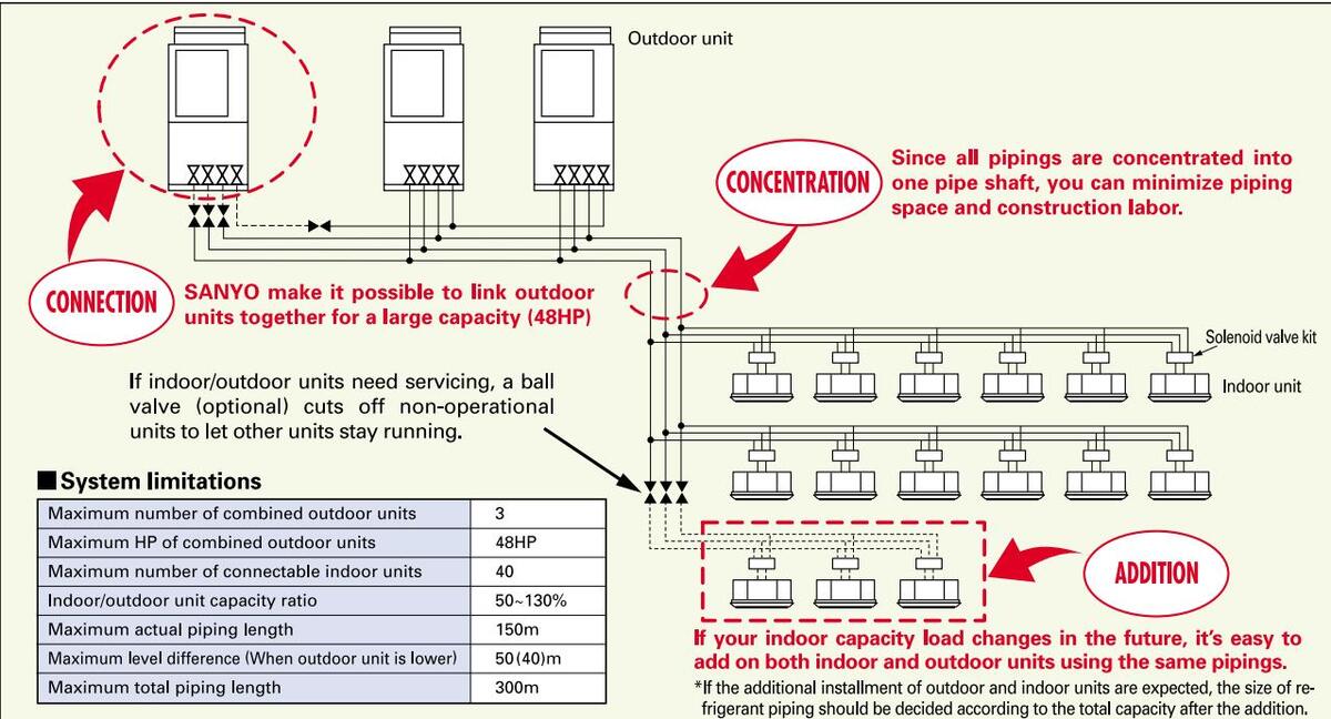
The 3 WAY ECO-i series has five DC inverter outdoor units from 8 HP to 16 HP as the basic models, and by combination of up to three units, an air-conditioning capacity of 8 HP to 48 HP can be set according to the user needs.
model
3 78

Reduction of the piping cost and construction labor by smaller piping size

Extended compressor life by uniform compressor operation times
2.52
-----
COP for heating and cooling.
The total operation time of the compressors is monitored by a microcomputer, so that there is no unbalance for the operation times of all compressors in the same refrigerant system, and compressors with a shorter operation time are operated with preference.
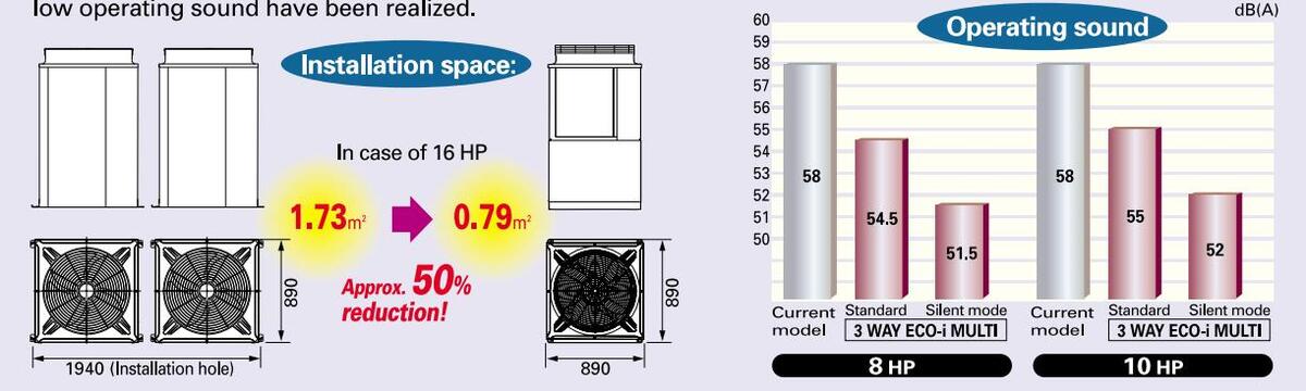
Smallest installation space in the industry! Further reduction of the operating sound
The five DC inverter types from 8 HP to 16 HP have been unified to the same external dimensions by using a tworoom construction with the compressor and other structural parts at the lower room of the outdoor unit and the heat exchanger at the upper room of the outdoor unit. In this way, the smallest installation space in the industry and low operating sound have been realized.
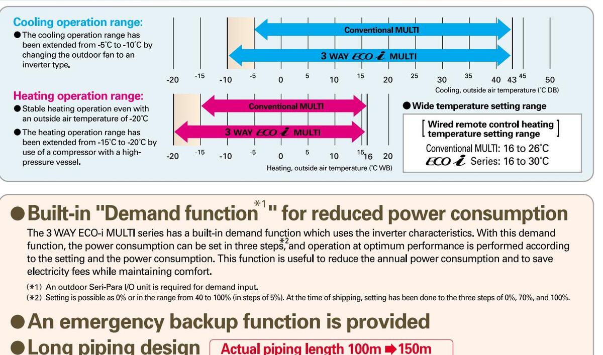
Extended operating range
Total piping length 150m ➡ 300m
Increased max. number of connectable indoor units
| System (HP) | 8 | 10 | 12 | 14 | 16 | 18 | 20 | 22 | 24~48 |
|---|---|---|---|---|---|---|---|---|---|
| Connectable indoor units | 13 | 16 | 19 | 23 | 26 | 29 | 33 | 36 | 40 |
Acres 10
3 WAY ECO-
3 WAY ECO 2 MULTI SYSTEM
Outdoor unit specifications
| А | ppearanc | æ | |||||
|---|---|---|---|---|---|---|---|
| н | Р | 8 | 10 | 12 | 14 | 16 | |
| N | lodel nan | ne (SPW-) | CR704GDZH8B | CR904GDZH8B | CR1154GDZH8B | CR1304GDZH8B | CR1404GDZH8B |
| Ρ | ower sup | ply | 380 | /400/415V-3 phase/50 | )Hz | ||
| (kW) | 22.4 | 28.0 | 33.5 | 40.0 | 45.0 | ||
| G | anacity | (BTU/h) | 76,400 | 95,500 | 114,300 | 136,500 | 153,600 |
| ľ | Heating (kW) | 25.0 | 31.5 | 37.5 | 45.0 | 50.0 | |
| (BTU/h) | 85,300 | 107,500 | 128,000 | 153,600 | 170,600 | ||
| Cooling (W/W) | 3.78 | 3.45 | 3.41 | 3.45 | 3.38 | ||
| Ľ | UP | Heating (W/W) | 4.09 | 3.95 | 3.81 | 3.91 | 3.79 |
| D | imensior | ns(H×W×D) (mm) | 1 | ,887 x 890 x 890 (+60 | ) | ||
| Ν | et weigh | it (kg) | 290 | 290 | 290 | 350 | 350 |
| Cooling | Running amperes (A) | 10.0/9.5/9.2 | 13.7/13.0/12.6 | 16.6/15.7/15.2 | 20.0/19.0/18.3 | 23.0/21.8/21.0 | |
| ating | oooning | Power input (kW) | 5.93 | 8.12 | 9.82 | 11.6 | 13.3 |
| rical r | Heating | Running amperes (A) | 10.3/9.8/9.4 | 13.5/12.8/12.3 | 16.6/15.8/15.2 | 19.9/18.9/18.2 | 22.8/21.6/20.9 |
| Electi | ricuting | Power input (kW) | 6.11 | 7.97 | 9.84 | 11.5 | 13.2 |
| Starting a | mperes (A) | 59/62/64 | 66/69/72 | 69/72/75 | 68/71/73 | 78/80/82 | |
| Α | ir circulat | ion (m³/min) | 150 | 160 | 180 | 200 | 220 |
| R | efrigerant a | mount at shipment (kg) | 11.8 | ||||
| Suction pipe (mm) | ø19.05 | ø22.22 | ø25.4 | ø25.4 | ø28.58 | ||
| Pi | ping | Discharge pipe (mm) | ø15.88 | ø19.05 | ø19.05 | ø22.22 | ø22.22 |
| C | onnection | Liquid pipe (mm) | ø9.52 | ø9.52 | ø12.7 | ø12.7 | ø12.7 |
| Balance pipe (mm) | ø9.52 | ø9.52 | ø9.52 | ø9.52 | ø9.52 | ||
| An | bient temp | erature operating range | Cooling/dry: -10° | C~+ 43°C (DB), Heating | : -20°C ~+15°C (WB) Sir | nultaneous operation: - | 10°C~+43°C (DB) |
| Pre | ssure sound | Normal mode dB(A) | 54.5 | 55 | 56 | 60 | 61 |
| ccare ocultu | Silent mode dB(A) | 51.5 | 52 | 53 | 57 | 58 | |
| Po | wer sound | Normal mode dB(A) | 65.5 | 66 | 67 | 71 | 72 |
* The values for performance and electric characteristics apply under the following test conditions. At the time of cooling: Indoor suction air temperature 27°C DB, 19°C WB, outdoor suction air temperature 35°C DB At the time of heating: Indoor suction air temperature 20°C DB, outdoor suction air temperature 7°C DB, 6°C WB
* The operating sound has been measured in an anechoic chamber, and it is the value one meter in front of the outdoor unit at a height of 1.5 m. With actual installation, the indication value normally differs widely according to the surrounding noise and reverberations.
* For mixed heating and cooling operation with an outdoor temperature in excess of 24°C DB, please use 50% or more of the horsepower of the outdoor unit for cooling operation.
3 WAY ECO i MULTI SYSTEM
OUTDOOR UNITS SPECIFICATIONS
| Appearanc | æ | |||||||||||
|---|---|---|---|---|---|---|---|---|---|---|---|---|
| НР | 8 | 10 | 12 | 14 | 16 | 18 | 20 | 22 | 24 | |||
| Model nam | ne (SPW-) | CR704GDZH8 | B CR904GDZH8B | CR1154GDZH8B | CR1304GDZH8B | CR1404GDZH8B |
CR704GDZH8B
CR904GDZH8B |
CR904GDZH8B
CR904GDZH8B |
CR904GDZH8B
CR1154GDZH8B |
CR904GDZH8B
CR1304GDZH8B |
||
| Power sup | ply | 380/4 | 00/415V-3pha | se/50Hz | ||||||||
| Cooling | (k | W) 22.4 | 28.0 | 33.5 | 40.0 | 45.0 | 50.4 | 56.0 | 61.5 | 68.0 | ||
| Capacity | cooling | (BT | U/h) 76,400 | 95,500 | 114,300 | 136,500 | 153,600 | 172,000 | 191,100 | 219,900 | 232,000 | |
| Heating | (k | W) 25.0 | 31.5 | 37.5 | 45.0 | 50.0 | 56.5 | 63.0 | 69.0 | 76.5 | ||
| nouting | (BT | U/h) 85,300 | 107,500 | 128,000 | 153,600 | 170,600 | 192,800 | 215,000 | 235,500 | 261,100 | ||
| COP | Cooling | (W | /W) 3.78 | 3.45 | 3.41 | 3.45 | 3.38 | 3.57 | 3.46 | 3.44 | 3.45 | |
| Heating | (W | /W) 4.09 | 3.95 | 3.81 | 3.91 | 3.79 | 4.01 | 3.96 | 3.88 | 3.92 | ||
| Dimensions | (HxWxD) | (m | im) | 1,8 | 87 x 890 x 890 | (+60) | 1,887 x 1,88 | 30 × 890 (+60) | ||||
| Net weight | I | (k | g) 290 | 290 | 290 | 350 | 350 | 580 | 580 | 580 | 640 | |
| Cooling Running a | nperes (, | A) 10.0/9.5/9.2 | 13.7/13.0/12.6 | 16.6/15.7/15.2 | 20.0/19.0/18.3 | 23.0/21.8/21.0 | 23.8/22.6/21.8 | 27.3/26.0/25.0 | 30.2/28.7/27.7 | 33.6/31.9/30.8 | ||
| Electrical | Cooling Heating mensions (HxWxD) t weight Cooling Running amperes Power input Heating Power input Heating Power input r circulation | W) 5.93 | 8.12 | 9.82 | 11.6 | 13.3 | 14.1 | 16.2 | 17.9 | 19.7 | ||
| ratings | Heating Running a | nperes (/ | A) 10.3/9.8/9.4 | 13.5/12.8/12.3 | 16.6/15.8/15.2 | 19.9/18.9/18.2 | 22.8/21.6/20.9 | 23.8/22.6/21.8 | 26.8/25.5/24.6 | 30.0/28.5/27.5 | 33.3/31.6/30.5 | |
| Power in | ut (k | W) 6.11 | 7.97 | 9.84 | 11.5 | 13.2 | 14.1 | 15.9 | 17.8 | 19.5 | ||
| Air circulat | ion | (m²) | min) 150 | 160 | 180 | 200 | 220 | 150+160 | 160+160 | 160+180 | 160+200 | |
| Refrigerant |
Itings Heating Running amperes
Power input ir circulation frigerant amount at shipment Suction pipe |
(g) | 00.00 | 11.8 | 05.4 | 00.50 | 00.50 | 23 | 3.6 | 00.50 | ||
| efrigerant amount at shipment Suction pipe Discharge pipe | Ø22.22 | Ø25.4 | 025.4 | Ø28.58 | Ø28.58 | ø28.58 | Ø28.58 | Ø28.58 | ||||
| Piping conne | ctions Discharge | pipe (m | m) Ø15.88 | Ø19.05 | 019.05 | 022.22 | 022.22 | 022.22 | 022.22 | 025.4 | 025.4 | |
| ; (m | (m) Ø9.52 | Ø9.52 | 012.7 | 012.7 | 012.7 | 015.88 | 015.88 | 015.88 | 015.88 | |||
| Ambiant tom | 09.52 | Cooling | 09.52 | C (DB) Hoati | 09.52 |
09.52
2:-10°C |
(DB) | |||||
| Ampient ten |
ianye
do dB |
E E | Ec | 1920 C~+15 C | E0 E | 61 5 | ||||||
| Operating so | und Silent me | (A) 54.5 | 50 | 52 | 57 | 50 | 55 | 55 | 55.5 | 595 | ||
| Silent mod | e | dB | (A) 01.5 | 52 | 53 | 57 | 56 | 00 | 00 | 00.0 | 08.0 | ||
Note: Rated conditions Cooling: indoor air temperature 27°C CB/19°C WB, outdoor air temperature 35°C DB
* For mixed heating and cooling operation with an outdoor temperature in excess of 24°C DR, nease use ower of the outdoor unit for cooling operation.
SYSTEM EXAMPLE
| 243 | 100 | 120 | 1 | 在不是 | ||||||||
|---|---|---|---|---|---|---|---|---|---|---|---|---|
| 1 | 100 | 1 | ||||||||||
| 26 | 28 | 30 | 32 | 34 | 36 | 38 | 40 | 42 | 44 | 46 | 48 | |
|
CR904GDZH8B
CR1404GDZH8B |
CR1154GDZH8B
CR1404GDZH8B |
CR1304GDZH8B
CR1404GDZH8B |
CR1404GDZH8B
CR1404GDZH8B |
CR904GDZH8B
CR904GDZH8B CR1304GDZH8B |
CR904GDZH8B
CR904GDZH8B CR1404GDZH8B |
CR904GDZH8B
CR1154GDZH8B CR1404GDZH8B |
CR904GDZH8B
CR1304GDZH8B CR1404GDZH8B |
CR904GDZH8B
CR1404GDZH8B CR1404GDZH8B |
CR1154GDZH8B
CR1404GDZH8B CR1404GDZH8B |
CR1304GDZH8B
CR1404GDZH8B CR1404GDZH8B |
CR1404GDZH8B
CR1404GDZH8B CR1404GDZH8B |
|
| 380/400/415 | /-3phase/50H | Z | ||||||||||
| 73.0 | 78.5 | 85.0 | 90.0 | 96.0 | 101.0 | 107.0 | 113.0 | 118.0 | 124.0 | 130.0 | 135.0 | |
| 249,100 | 267,900 | 290,100 | 307,100 | 327,600 | 344,700 | 363,400 | 385,600 | 402,700 | 421,400 | 443,600 | 460,700 | |
| 81.5 | 87.5 | 95.0 | 100.0 | 108.0 | 113.0 | 119.0 | 127.0 | 132.0 | 138.0 | 145.0 | 150.0 | |
| 278,100 | 300,300 | 324,200 | 343,000 | 368,500 | 385,600 | 407,800 | 431,700 | 450,400 | 470,900 | 494,800 | 511,900 | |
| 3.41 | 3.40 | 3.41 | 3.38 | 3.45 | 3.41 | 3.42 | 3.42 | 3.40 | 3.41 | 3.40 | 3.38 | |
| 3.84 | 3.80 | 3.85 | 3.79 | 3.93 | 3.88 | 3.84 | 3.88 | 3.84 | 3.81 | 3.83 | 3.79 | |
| 0.10 | 1,887 x 1,880 | x 890 (+60) | 700 | 1,887 x 2,870 | x 890 (+60) | 1.050 | 1.050 | |||||
| 640 | 640 | /00 | /00 | 930 | 930 | 930 | 990 | 990 | 990 | 1,050 | 1,050 | |
| 36.5/34.7/33.5 | 39.4/37.5/36.1 | 43.0/40.8/39.4 | 45.9/43.6/42.1 | 47.5/45.1/43.5 | 50.5/48.0/46.3 | 53.0/51.0/49.0 | 57.0/54.0/52.0 | 00.0/57.0/55.0 | 63.0/60.0/58.0 | 00.0/03.0/00.0 | 09.0/05.0/03.0 | |
| 21.4 | 23.1 |
24.9
12.6/10.5/30.0 |
20.0
45.6//3.3//1.7 |
27.0
16.9/11.6/13.0 |
29.0
10.7/17.2/15.5 |
53 0/50 0/48 0 | 56.0/54.0/52.0 | 59.0/56.0/54.0 | 63 0/59 0/57 0 |
50.2
65.0/62.0/60.0 |
59.9
68.0/65.0/63.0 |
|
| 21.2 | 23.0 | 24.7 | 26.4 | 27.5 | 29.1 | 31.0 | 32.7 | 34.4 | 36.2 | 37.9 | 39.6 | |
| 160+220 | 180+220 | 200+220 | 220+220 | 160+160+200 | 160+160+220 | 160+180+220 | 160+200+220 | 160+220+220 | 180+220+220 | 200+220+220 | 220+220+220 | |
| 23 | 3.6 | 38 | 5.4 | |||||||||
| ø31.75 | ø31.75 | ø31.75 | ø31.75 | ø31.75 | ø38.1 | ø38.1 | ø38.1 | ø38.1 | ø38.1 | ø38.1 | ø38.1 | |
| ø25.4 | ø28.58 | ø28.58 | ø28.58 | ø28.58 | ø28.58 | ø31.75 | ø31.75 | ø31.75 | ø31.75 | ø31.75 | ø31.75 | |
| ø19.05 | ø19.05 | ø19.05 | ø19.05 | ø19.05 | ø19.05 | ø19.05 | ø19.05 | ø19.05 | ø19.05 | ø19.05 | ø19.05 | |
| ø9.52 | ø9.52 | ø9.52 | ø9.52 | ø9.52 | ø9.52 | ø9.52 | ø9.52 | ø9.52 | ø9.52 | ø9.52 | ø9.52 | |
| Coolir | ıg/Dry: -10°C∼+ | 43°C (DB), Hea | ating: -20°C~+1 | 5°C (WB) Simu | ltaneous operat | ion: -10°C~+24 | °C (DB) | |||||
| 62 | 62.5 | 63.5 | 64 | 62.5 | 63 | 63 | 64.5 | 64.5 | 65 | 65.5 | 66 | |
| - EO E | 60.5 | 61 | 59.5 | 60 | 60 | 615 | 615 | 62 | 62.5 | 63 |
Data subject to change without notice.
DIMENSION OF UNIT COMBINATIONS
NINI ECO-i
WAY ECO-i 5N serie
3 WAY ECO-i
IDOOR UNITS
FIONAL PARTS
3 WAY ECO 1 MULTI SYSTEM
Piping design
Ranges that apply to refrigerant piping lengths and to differences in installation heights
| Items | Marks | Contents | Length (m) | |
|---|---|---|---|---|
| 11 | May piping longth | Actual piping length | ≦150 | |
| wax. piping length | Equivalent piping length | ≦175 | ||
| Allowable | ∆L (L2 —L4) | Difference between the max. In the No.1 distribution joint | ength and the min. length from | ≦40 |
| piping length | LM | Max. length of main piping | (at max. diameter) | ≦80 |
| 1, 2~40 | Max. length of each distribu | ution | ≦30 | |
|
L1+1+2+~40
+A+B+LF+LG+LH |
Total max. piping length ind
distribution (only narrow tu |
cluding length of each
bing) |
≦300 | |
| L5 | Distance between PC and A | D unit | ≦10 | |
| 111 | When outdoor unit is installed | higher than indoor unit | ≦50 | |
| Allowable | When outdoor unit is installed | lower than indoor unit | ≦40 | |
| difference | H2 | Max. difference between in | door units | ≦15 |
| НЗ | Max. difference between ou | utdoor units | ≦4 |
Note 1: The outdoor connection main piping (LO part) depends on the total capacity of the outdoor units connected to the end. Note 2: When the main piping length (L1) (equivalent length) exceeds 90 m, increase the size of both the gas and liquid
main piping (LM) by 1 step.
Distribution joint kits
| Remarks | Model name | Cooling capacity after distribution |
|---|---|---|
| 1. APR-CHRZP680BGB | 68.0 kW or less | |
| For outdoor unit | 2. APR-CHRZP1350BGB | 135.0 kW or less |
| 3. APR-RZP224BGB | 22.4 kW or less | |
| For indoor unit | 4. APR-RZP680BGB | 68.0 kW or less |
| 5. APR-RZP1350BGB | 135.0 kW or less |
| outdoor units | 135 kW (48 hp) |
|---|---|
|
Max. number of connectable
indoor units |
40 |
| Indoor/outdoor unit capacity ratio | 50-130% |
Additional refrigerant charge
| Liquid piping size | Amount of refrigerant charge/m (g/m) |
| ø6.35 | 26 |
| ø9.52 | 56 |
| ø12.7 | 128 |
| ø15.88 | 185 |
| ø19.05 | 259 |
| ø22.22 | 366 |
Refrigerant piping
| Piping s | ize (mm) | ||
|---|---|---|---|
| 0 mat | erial | 1/2 H, H | material |
| Outer diameter | Wall thickness | Outer diameter | Wall thickness |
| ø 6.35 | t 0.8 | ø 25.4 | t 1.0 |
| ø 9.52 | t 0.8 | ø 28.58 | t 1.0 |
| ø 12.7 | t 0.8 | ø 31.75 | t 1.1 |
| ø 15.88 | t 1.0 | ø 38.1 | t 1.15 |
| ø 19.05 | t 1.0 | ø 41.28 | t 1.20 |
| ø 22.22 | t 1.15 | ||
| 140 2 1 12 | 1.1.1.1.1.1.1.1.1 | 1 |
Note: When pipe bending is to be performed, the bending radius shall be at least 4 times the outer diameter. Also, take sufficient care to prevent pipe collapse and damage at the time of bending
And in case
■3 WAY ECO-i MULTI piping sizes
• Main pipe sizes (LA)
| HP | 8 | 10 | 12 | 14 | 16 | 18 | 20 | 22 | 24 | 26 | 28 | 30 | 32 | 34 | 36 | 38 | 40 | 42 | 44 | 46 | 48 |
|---|---|---|---|---|---|---|---|---|---|---|---|---|---|---|---|---|---|---|---|---|---|
| Combined outdoor units | 8 | 10 | 12 | 14 | 16 |
10
8 |
10
10 |
12
10 |
14
10 |
16
10 |
16
12 |
16
14 |
16
16 |
14
10 10 |
16
10 10 |
16
12 10 |
16
14 10 |
16
16 10 |
16
16 12 |
16
16 14 |
16
16 16 |
| Suction pipe (mm) | ø19.05 | ø22.22 | ø2 | 5.4 | ø28.58 | ø31.75 | ø38.1 | ||||||||||||||
| Discharge pipe (mm) | ø15.88 | ø19 | .05 | ø22 | .22 | ø25.4 | ļ | ø 28. 58 | ø31 | 75 | |||||||||||
| Liquid pipe (mm) | ø9. | 52 | ø12.7 | ø15 | . 88 | ø19 | .05 |
te 1: When future expansion is planned, select the piping diameter according to the total HP after expansion.
Note 1: When future expansion is planned, select the piping dameter according to the teach and the discharge pipe shall be increased by one size from the Note 3: Max. length for the main pipe (LM); when the length exceeds 50 m, the size of the suction pipe and the discharge pipe shall be increased by one size from the main pipe size up to 50 m. (For lengths in excess of 50 m, select from the above main pipes size table.)
Main piping size between outdoor units (LO)
Select the piping size between outdoor units according to the main pipe size (LA) of the above table.
Main tubing size after distribution (LB, LC, ...)
| Total capacity | Below kW | 7 . 1 | 16.0 | 26.2 | 30.0 | 36.4 | 42.0 | 47.6 | 58.8 | 70.0 | 75.6 | 98.0 | 103.6 | — |
|---|---|---|---|---|---|---|---|---|---|---|---|---|---|---|
| after distribution | Over kW | _ | 7.1 | 16.0 | 26.2 | 30.0 | 36.4 | 42.0 | 47.6 | 58.8 | 70.0 | 75.6 | 98.0 | 103.6 |
| Suction pipe (mm) | ø 15.88 | ø 19.05 | ø 19.05 | ø 22.22 | ø 25.4 | ø 25.4 | ø 28.58 | ø 28.58 | ø 28.58 | ø 31.75 | ø 31.75 | ø 38.1 | ø 38.1 | |
| Piping size | Discharge pipe (mm) | ø 12.7 | ø 15.88 | ø 15.88 | ø 19.05 | ø 19.05 | ø 22.22 | ø 22.22 | ø 22.22 | ø 25.4 | ø 25.4 | ø 28.58 | ø 28.58 | ø 31.75 |
| Liquid pipe (mm) | ø 9.52 | ø 9.52 | ø 9.52 | ø 9.52 | ø 12.7 | ø 12.7 | ø 12.7 | ø 15.88 | ø 15.88 | ø 19.05 | ø 19.05 | ø 19.05 | ø 19.05 |
Note 1: The outdoor unit connection main pipe (LO part) depends on the total capacity of the outdoor units connected to the end. Select the piping size from the table for the main pipe
Note 2: When the total capacity of the indoor units connected to the end differs from the total capacity of the outdoor units, select the main pipe size according to the total capacity of the outdoor units. (Especially the main pipe part of LA, LB, LF, etc.)
Indoor unit connection piping (1 to 40)
| Indoor unit typ | be | 7 type | 9 type | 12 type | 16 type | 18 type | 25 type | 36 type | 48 type | 60 type | 76 type *1 | 96 type *1 | |
|---|---|---|---|---|---|---|---|---|---|---|---|---|---|
| Equivalent HP | 0.8 | 1 | 1.3 | 1.6 | 2 | 2.5 | 4 | 5 | 6 | 8 | 10 | ||
| Pining between | Suction pipe | (mm) | ø 15 . 88 | ø 19.05 | ø 22.22 | ||||||||
| distribution and | Discharge pip | e (mm) | ø 12.7 | ||||||||||
| solenoid valve kit |
noid valve kit
Liquid pipe (mm) Ø 9.52 |
||||||||||||
|
Piping between
solenoid valve kit |
Gas pipe | (mm) | ø 12.7 ø 15.88 ø | ø 19 . 05 | ø 22 . 22 | ||||||||
|
and indoor
connection piping |
Liquid pipe | (mm) | ø 6.35 | ø 9.! | 52 | ||||||||
**1 When an indoor unit of type 76 or 96 is used, use the type 160 solenoid valve kit in parallel specification and branch the piping before/after the solenoid valve kit.

Downloaded from www.Manualslib.com manuals search engine
3 WAY ECO-
Wide choice of models depending on the indoor requirements
| Model size | 7 | 9 | 12 | 16 | 18 | 22 |
|---|---|---|---|---|---|---|
|
kW Cooling
Heating |
2.2
2.5 |
2.8
3.2 |
3.6
4.2 |
4.5
5.0 |
5.6
6.3 |
6.4
7.0 |
|
BTU/h Cooling
Heating |
7,500
8,500 |
9,600
11,000 |
12,000
14,000 |
15,000
17,000 |
19,000
21,000 |
22,000
24,000 |
|
XIII type (600 x 600)
Semi-Concealed Cassette 4-Way Air Discharge |
SPW-XM075XH
Panel PNR-XM185 |
SPW-XM095XH
Panel PNR-XM185 |
SPW-XM125XH
Panel PNR-XM185 |
SPW-XM165XH
Panel PNR-XM185 |
SPW-XM185XH
Panel PNR-XM185 |
|
|
X type
Semi-Concealed Cassette 4-Way Air Discharge |
SPW-X075XH
Panel PNR-XD484GHAB |
SPW-X095XH
Panel PNR-XD484GHAB |
SPW-X125XH
Panel PNR-XD484GHAB |
SPW-X165XH
Panel PNR-XD484GHAB |
SPW-X185XH
Panel PNR-XD484GHAB |
|
|
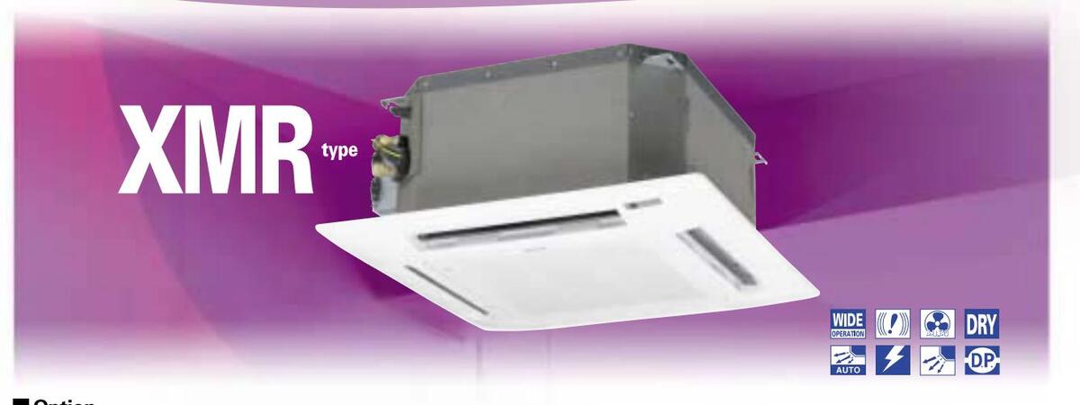
XMR type (600 x 600)
Semi-Concealed Cassette 4-Way Air Discharge |
SPW-XMR74EXH56B
Panel PNR-XM184EHA |
SPW-XMR94EXH56B
Panel PNR-XM184EHA |
SPW-XMR124EXH56B
Panel PNR-XM184EHA |
SPW-XMR164EXH56B
Panel PNR-XM184EHA |
SPW-XMR184EXH56B
Panel PNR-XM184EHA |
|
|
SR type
Semi-Concealed Cassette 2-Way Air Discharge |
SPW-SR74GXH56B
Panel PNR-S124GHB |
SPW-SR94GXH56B
Panel PNR-S124GHB |
SPW-SR124GXH56B
Panel PNR-S124GHB |
SPW-SR164GXH56B
Panel PNR-S124GHB |
SPW-SR184GXH56B
Panel PNR-S124GHB |
|
|
ADR type
Semi-Concealed Cassette 1-Way Air Discharge |
SPW-ADR74GXH56B
Panel PNR-AD124GHB |
SPW-ADR94GXH56B
Panel PNR-AD124GHB |
SPW-ADR124GXH56B
Panel PNR-AD124GHB |
|||
|
LDR type
Semi-Concealed Slim Cassette |
SPW-LDR94GXH56B
Panel PNR-LD254GHAB |
SPW-LDR124GXH56B
Panel PNR-LD254GHAB |
SPW-LDR164GXH56B
Panel PNR-LD254GHAB |
SPW-LDR184GXH56B
Panel PNR-LD254GHAB |
||
|
U type
Concealed Duct |
SPW-U075XH | SPW-U095XH | SPW-U125XH | SPW-U165XH | SPW-U185XH | |
|
UR type
Concealed-Rectangle Duct |
SPW-U075SXHT | SPW-U095SXHT | SPW-U125SXHT | SPW-U165SXHT | SPW-U185SXHT | |
|
US type
Concealed Duct |
SPW-US075XH | SPW-US095XH | SPW-US125XH | SPW-US165XH | SPW-US185XH | |
|
FUR type
Floor/Ceiling Slim Concealed Duct |
SPW-FUR74EXH56B | SPW-FUR94EXH56B | SPW-FUR124EXH56B | SPW-FUR164EXH56B | SPW-FUR184EXH56B | SPW-FUR224EXH56B |
|
UMR type
Concealed Duct |
SPW-UMR74EXH56B | SPW-UMR94EXH56B | SPW-UMR124EXH56B | SPW-UMR164EXH56B | SPW-UMR184EXH56B | SPW-UMR224EXH56B |
|
DR type
Concealed Duct High-Static Pressure |
||||||
|
T type Ceiling-
Mounted Units |
SPW-T125XH | SPW-T165XH | SPW-T185XH | |||
|
FTR type
Floor/Ceiling Mounted Units |
SPW-FTR74EXH56B | SPW-FTR94EXH56B | SPW-FTR124EXH56B | SPW-FTR164EXH56B | SPW-FTR184EXH56B | SPW-FTR224EXH56B |
|
K type
Wall Mounted Units |
SPW-K075XH | SPW-K095XH | SPW-K125XH | |||
|
KR type
Wall-Mounted Units |
SPW-KR74GXH56B | SPW-KR94GXH56B | SPW-KR124GXH56B | SPW-KR164GXH56B | SPW-KR184GXH56B | |
|
FMR type
Concealed Floor Standing Units |
SPW-FMR74GXH56B | SPW-FMR94GXH56B | SPW-FMR124GXH56B | SPW-FMR164GXH56B | SPW-FMR184GXH56B | |
|
FR type Floor
Standing Units |
SPW-FR74GXH56B | SPW-FR94GXH56B | SPW-FR124GXH56B | SPW-FR164GXH56B | SPW-FR184GXH56B | |
|
GU type
Total Heat Exchanger with DX coil |
SPW-GU055XH | SPW-GU075XH | SPW-GU105XH |
| 25 | 30 | 36 | 48 | 60 | 76 | 96 | Wireless re | mote control | |
|---|---|---|---|---|---|---|---|---|---|
| 7.3 | 9.0 | 10.6 | 14.0 | 16.0 | 22.4 | 28.0 | Type with | Type with | Function |
| 25,000 |
30,000
34,000 |
36,000
39,000 |
47,800
54,600 |
54,600
61,500 |
76,400
85,300 |
95,500 | reception |
installed
reception |
, uncroin |
| • | • |
NUER (III)
IIII) (IIII) (IIII) (IIIII) (IIIII) (IIIIII) (IIIII) |
|||||||
|
SPW-X255XH
Panel PNR-XD484GHAB |
SPW-X365XH
Panel PNR-XD484GHAB |
SPW-X485XH
Panel PNR-XD484GHAB |
SPW-X605XH
Panel PNR-XD484GHAB |
• | • | ||||
| • | • | ||||||||
|
SPW-
SR254GXH56B Panel PNR-S253GHANB |
• | • | |||||||
| • | • |
₩
₩
₩ ₩ ₩ ₩ ₩ ₩ ₩ ₩ ₩ ₩ ₩ ₩ ₩ |
|||||||
|
SPW-
LDR254GXH56B Panel PNR-LD254GHAB |
• | • |
₩₽₽
₩₽₽ ₩₽₽ ₩₽₽ ₩₽₽ ₩₽₽ ₩₽₽ |
||||||
| SPW-U255XH | SPW-U365XH | SPW-U485XH | SPW-U605XH | • | |||||
| SPW-U255SXHT | SPW-U305SXHT | SPW-U365SXHT | SPW-U485SXHT | SPW-U605SXHT | • | ||||
| • | |||||||||
| • | |||||||||
| • | |||||||||
|
SPW-
DR254GXH56B |
SPW-
DR364GXH56B |
SPW-
DR484GXH56B |
SPW-
DR764GXH56B |
SPW-
DR964GXH56B |
• | ||||
| SPW-T255XH | SPW-T365XH | SPW-T485XH | • | • | |||||
| • | • | WILE CON CAN DRY | |||||||
| • | • |
WILLS (IV) CAN DRY
EVENTS I CON |
|||||||
|
SPW-
KR254GXH56B |
• | • | WILE CON CAN DRY | ||||||
|
SPW-
FMR254GXH56B |
• | ||||||||
|
SPW-
FR254GXH56B |
• |
SEMI-CONCEALED 4-WAY AIR DISCHARGE
| Model nam | ne . | (S | SPW-) | XM075XH | XM095XH | XM125XH | XM165XH | XM185XH | ||
|---|---|---|---|---|---|---|---|---|---|---|
| Power sour | ce | 220 |
|
/230/240V, 1 phase-50, 6 |
0Hz | ||||||
| kW | 22 | 28 | 36 | 47 | 56 | |||||
| Cooling cap | acity | BTU/h | 7,500 | 9,600 | 12,000 | 15,000 | 19.000 | |||
| kW | 2.5 | 3.2 | 4.0 | 5.0 | 6.3 | |||||
| Heating cap | acity | BTU/h | 8,500 | 11,000 | 14,000 | 17,000 | 21,000 | |||
| Moisture Re | moval ( | High) | Liters/h | 0.2 | 0.6 | 1.1 | 1.5 | 1.9 | ||
| Power input Cooling kW | 0.024/0.0 | 25 / 0.025 | 0.026/0.027/0.027 | 0.030/0.031/0.031 | 0.037/0.038/0.038 | |||||
| i owei input | Heating | kW | 0.014/0.0 | 15/0.015 | 0.017/0.017/0.018 | 0.020/0.021/0.021 | 0.029/0.029/0.029 | |||
| Dunning amports Cooling | А | 0.16/0.1 | 6/0.15 | 0.18/0.18/0.17 | 0.21/0.21/0.20 | 0.29/0.29/0.28 | ||||
| Running an | iperes | Heating | А | 0.13/0.1 | 3/0.12 | 0.15/0.15/0.14 | 0.18/0.18/0.17 | 0.26/0.26/0.25 | ||
| Туре | Centrifugal fan | |||||||||
| Fan motor | Airflow | / rate (H/M/L) | m³/min | 8/7 | 7/6 | 9/8/7 | 10.7 / 8.5 / 7.5 | 12.5/10.5/9 | ||
| Outpu | t kW | 0.020 | ||||||||
| Power sound | d level ( | H/M/L) | dB(A) | 46 / 4 | 3/41 | 49 / 46 / 42 | 53 / 48 / 45 | 58 / 54 / 50 | ||
| Operating so | ound (H | /M/L) | dB(A) | 30 / 2 | 7 / 25 | 32 / 29 / 26 | 36 / 32 / 28 | 41 / 37 / 33 | ||
| ŀ | leight | mm | 283 | |||||||
| Dimensions | ١ | Nidth | mm | 575 <625> | ||||||
| 0 | Depth | mm | 575 <625> | |||||||
| Liquid (Flare) | mm | 6.35 (1/4) | ||||||||
| Piping conne | ctions | Gas (Flare) | mm | 12.7 (1/2) | ||||||
| Drain piping | VP-20 | |||||||||
| Net weight | kg | 16 + <2.4> | ||||||||
| Rated conditions | * The | values in C > for external dime | sions and net weight are the val | ues for the ontional ceiling nanel | ||||||
Indoor units specifications
Rated conditions Cooling: Indoor air temperature 27°C DB/19°C WB, outdoor air temperature 35°C DB Heating: Indoor air temperature 20°C DB, outdoor air temperature 7°C DB/6°C WB
eight are the values for the optional centry parter. Data subject to change without notice.
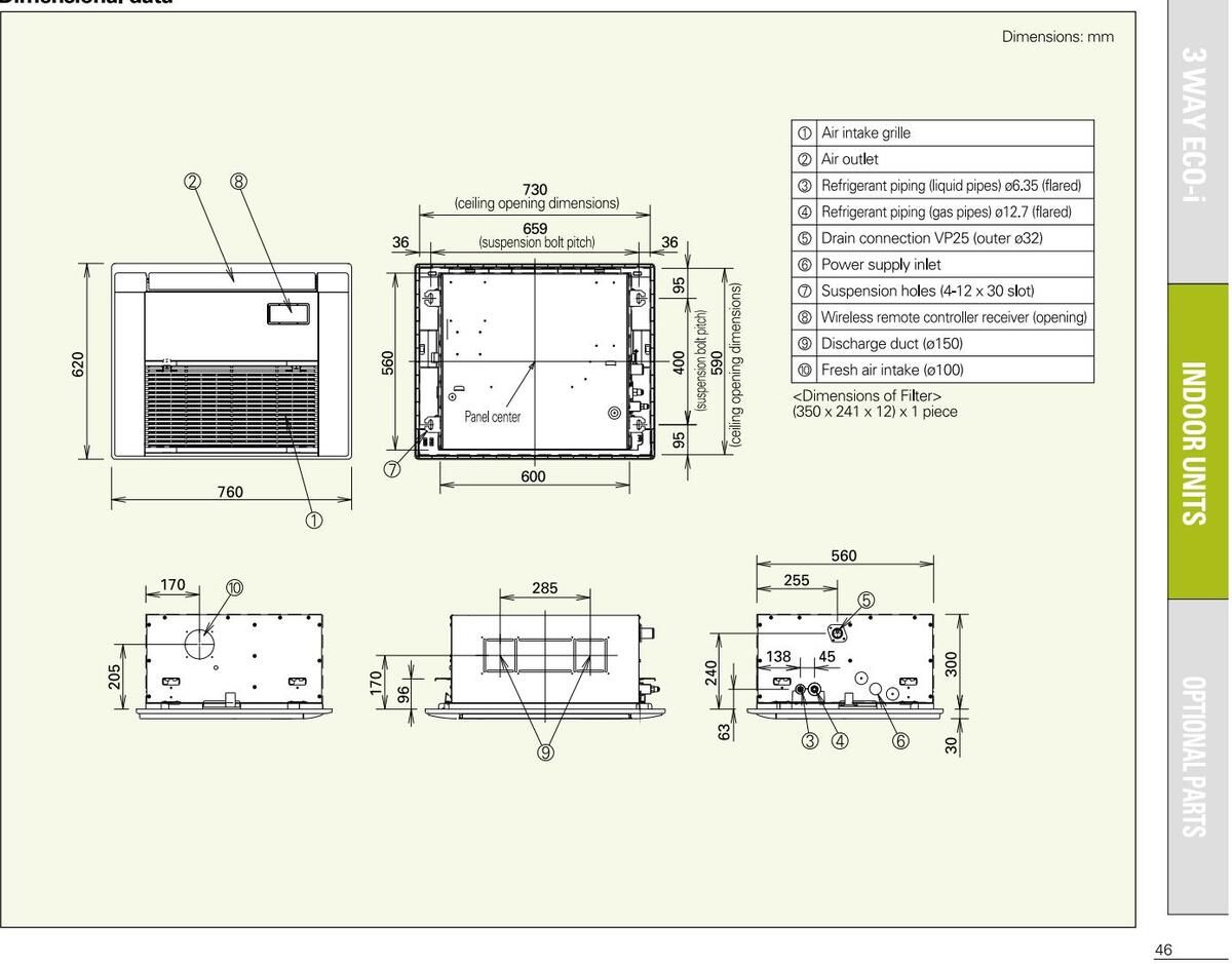
Dimensional data
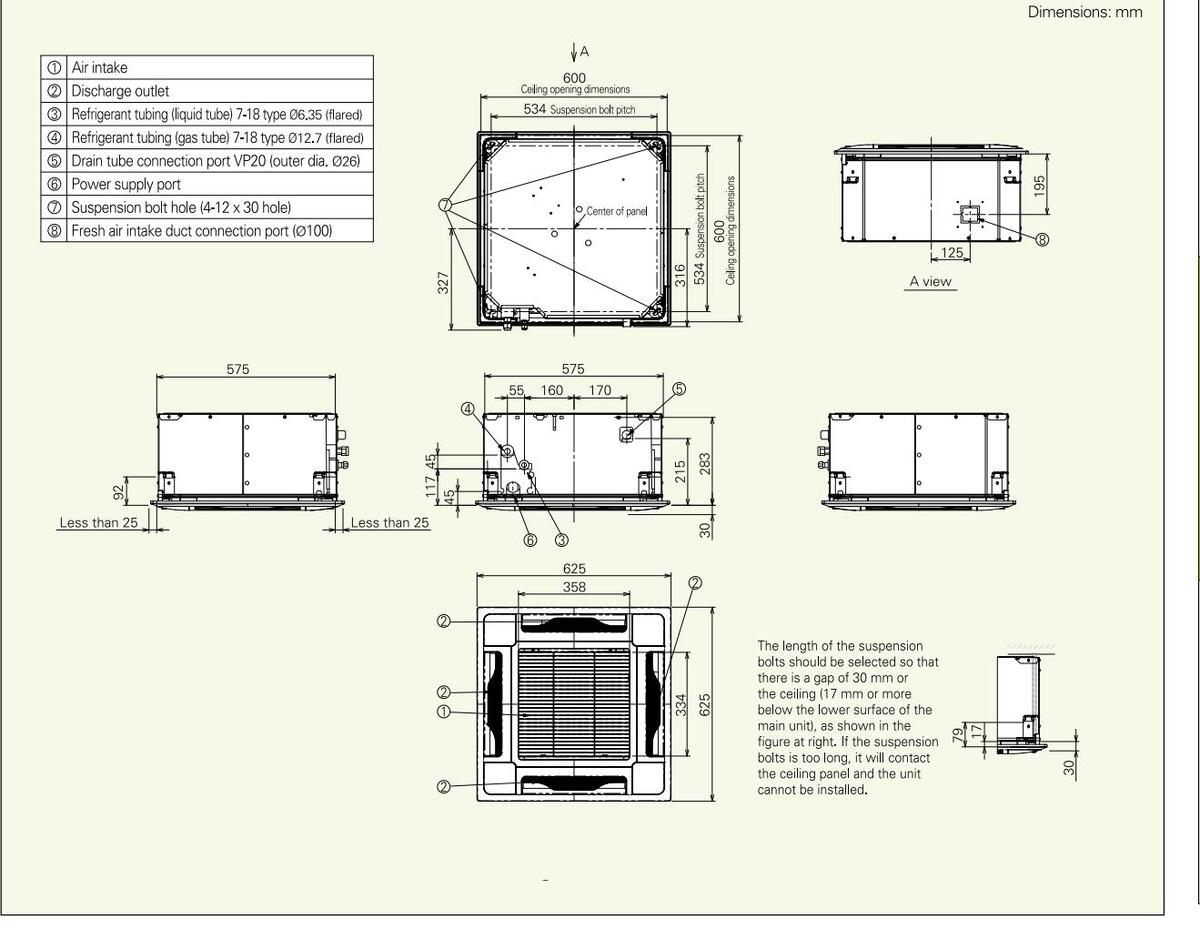
Downloaded from www.Manualslib.com manuals search engine
SEMI-CONCEALED CASSETTE 4-WAY AIR DISCHARGE
| Model name (SPW-) X075XH X095XH X125XH X165XH X185XH X255XH X365XH R Power source 220/230/240V, 1 phase-50, 60Hz 220/230/240V, 1 phase-50, 60Hz 5 6 7.3 10.6 1 Cooling capacity KW 2.2 2.8 3.6 4.5 5.6 7.3 10.6 1 Heating capacity KW 2.2 2.8 3.6 4.5 5.6 7.3 10.6 1 Heating capacity KW 2.5 3.2 4.2 5.0 6.3 8.0 11.4 1 Power input Cooling KW 0.035/0.035/0.035 0.0390.040/0.41 0.052/0.052/0.052 0.390.003 0.34/0.33/0.32 0.34/0.030.033 0.042/0.043/0.043 0.042/0.043/0.042 0.05 0.31/0.30/0.30 0.34/0.33/0.32 0.34/0.050/0.050/0.05 0.31/0.30/0.30 0.34/0.33/0.32 0.34/0.042/0.043/0.042 0.042/0.043/0.042 0.042/0.043/0.042 0.040 | ||||||||||
|---|---|---|---|---|---|---|---|---|---|---|
| Power source 220/230/240V, 1 phase-50, 60 Hz Cooling capacity kW 2.2 2.8 3.6 4.5 5.6 7.3 10.6 BTU/h 7,500 9,600 12,000 15,000 19,000 25,000 36,000 Heating capacity kW 2.5 3.2 4.2 5.0 6.3 8.0 11.4 BTU/h 8,500 11,000 14,000 17,000 21,000 27,000 39,000 Power input Cooling kW 0.035/0.036 0.039(0.040/0.041 0.042(0.043(0.044 0.052(0.053 0.082/0.083(0.082) 0.1 Heating kW 0.027/0.027/0.028 0.039(0.031/0.032 0.032(0.033(0.034 0.042(0.043(0.043) 0.074(0.076(0.077) 0.1 Running amperes Cooling A 0.27/0.27/0.26 0.31/0.30/0.30 0.34/0.33(0.32 0.43(0.42)(0.43(0.43 0.64(0.63/0.66) 0.31/0.30/0.30 0.34/0.32(0.33(0.35 0.64(0.63/0.66) 0.31/0.30/0.30 0.34/0.32(0.33(0.35 0.64(0.63/0.66) 0.31/0.30/0.30 0.34/0.32(0.32)(0.28)(0.38)(0.36)(0.54) 0.54(0 | X485XH | X605XH | ||||||||
|
KW
2.2
2.8
3.6
4.5
5.6
7.3
10.6
BTU/h
7,500
9,600
12,000
15,000
19,000
25,000
36,000
Heating capacity
KW
2.5
3.2
4.2
5.0
6.3
8.0
11.4
Power input
Cooling
Heating kW 0.035/0.035/0.036 0.039/0.0400.041 0.042/0.043/0.044 0.052/0.520.053 0.082/0.083/0.083 0.1 Running ampere Cooling Heating A 0.27/0.27/0.028 0.39/0.031/0.302 0.34/0.33/0.32 0.43/0.42/0.41 0.67/0.63/0.60 0.5 Running ampere Cooling Heating A 0.27/0.27/0.22 0.26/0.25/0.25 0.29/0.28/0.28 0.38/0.36/0.35 0.64/0.63/0.62 0.5 |
220/230/240V, 1 phase-50, 60 Hz | |||||||||
| BTU/h 7,500 9,600 12,000 15,000 19,000 25,000 36,000 Heating capacity kW 2.5 3.2 4.2 5.0 6.3 8.0 11.4 7.00 Power input Cooling kW 0.035/0.035/0.035 0.339/0.0400.041 0.42/0.043/0.044 0.52/0.052/0.053 0.082/0.083/0.083 0.1 Power input Heating kW 0.027/0.027/0.028 0.339/0.0400.041 0.42/0.043/0.044 0.52/0.052/0.053 0.082/0.083/0.035 0.1 Running ampere Cooling A 0.27/0.27/0.22 0.31/0.30/0.03 0.34/0.33/0.32 0.43/0.42/0.41 0.67/0.63/0.60 0.5 Running ampere Cooling A 0.23/0.23/0.22 0.36/0.25/0.25 0.29/0.28/0.28 0.38/0.36/0.35 0.64/0.63/0.62 0.3 | 14.0 | 16.0 | ||||||||
| Heating capacity KW 2.5 3.2 4.2 5.0 6.3 8.0 11.4 BTU/h 8,500 11,000 14,000 17,000 21,000 27,000 39,000 1 Power input Cooling KW 0.035/0.035/0.035/0.03 0.039/0.040/0.041 0.042/0.043/0.044 0.052/0.027/0.027 0.039/0.040/0.041 0.042/0.043/0.044 0.052/0.052/0.057 0.1 Running ampere Cooling A 0.27/0.27/0.25 0.31/0.30/0.03 0.34/0.33/0.32 0.43/0.42/0.41 0.67/0.63/0.60 0.5 Running ampere Cooling A 0.23/0.23/0.22 0.26/0.25/0.25 0.29/0.28/0.28 0.38/0.36/0.35 0.64/0.63/0.62 0.5 | 47,800 | 54,600 | ||||||||
| Beaufing capacity BTU/h 8,500 11,000 14,000 17,000 21,000 27,000 39,000 39,000 Power input Cooling kW 0.035/0.035/0.035 0.039/0.040/0.041 0.042/0.043/0.044 0.052/0.052/0.053 0.082/0.083/0.083 0.1 Heating kW 0.027/0.027/0.028 0.039/0.040/0.041 0.042/0.043/0.044 0.052/0.053/0.037 0.1 Running ampere Cooling A 0.27/0.27/0.22 0.31/0.30/0.30 0.34/0.33/0.32 0.43/0.42/0.41 0.67/0.63/0.60 0.5 Heating A 0.23/0.23/0.22 0.26/0.25/0.25 0.29/0.28/0.28 0.38/0.36/0.35 0.64/0.63/0.62 0.3 | 16.0 | 18.0 | ||||||||
|
Power input
Cooling
Heating kW 0.035/0.035/0.036 0.039/0.040/0.041 0.042/0.043/0.044 0.052/0.052/0.053 0.082/0.083/0.083 0.1 Running ampere Cooling A 0.027/0.027/0.028 0.039/0.030/0.031/0.032 0.032/0.033/0.034 0.042/0.043/0.043 0.074/0.076/0.077 0.1 Running ampere Cooling A 0.23/0.23/0.22 0.26/0.25/0.25 0.29/0.28/0.28 0.38/0.36/0.35 0.64/0.63/0.62 0.3 |
54,600 | 61,400 | ||||||||
| Heating kW 0.027/0.027/0.028 0.030/0.031/0.032 0.032/0.033/0.034 0.042/0.043/0.043 0.074/0.076/0.077 0.7 Running ampere Cooling A 0.227/0.27/0.26 0.31/0.30/0.30 0.34/0.33/0.32 0.43/0.42/0.41 0.67/0.63/0.60 0.4 Heating A 0.23/0.23/0.22 0.26/0.25/0.25 0.29/0.28/0.28 0.38/0.36/0.35 0.64/0.63/0.62 0.4 | .111/0.112/0.113 | 0.117/0.118/0.122 | ||||||||
| Cooling A 0.27/0.27/0.26 0.31/0.30/0.30 0.34/0.33/0.32 0.43/0.42/0.41 0.67/0.63/0.60 0.3 Heating A 0.23/0.23/0.22 0.26/0.25/0.25 0.29/0.28/0.28 0.38/0.36/0.35 0.64/0.63/0.62 0.3 | 1.103/0.103/0.104 | 0.108/0.108/0.111 | ||||||||
| Heating A 0.23/0.23/0.22 0.26/0.25/0.25 0.29/0.28/0.28 0.38/0.35 0.64/0.63/0.62 0.3 Type Turbo fan *1 | ).91/0.88/0.84 | 0.97/0.92/0.92 | ||||||||
| Type Turbo fan *1 | ).89/0.88/0.86 | 0.96/0.95/0.93 | ||||||||
| Turbo fan *1 | ||||||||||
| Fan motor Airflow rate (H/M/L) m 3 /min 15.5/14/13 16/14/13 20/16/14 28/23/21 | 33/25/22 | 34/27/23 | ||||||||
| Output kW 0.05 | 0.09 | |||||||||
| Power sound level (H/M/L) dB(A) 42/40/38 45/42/39 50/47/44 5 | 53/49/45 | 55/51/47 | ||||||||
| Pressure sound level (H/M/L) dB(A) 31/29/27 34/31/28 39/36/33 4 | 42/38/34 | 44/40/36 | ||||||||
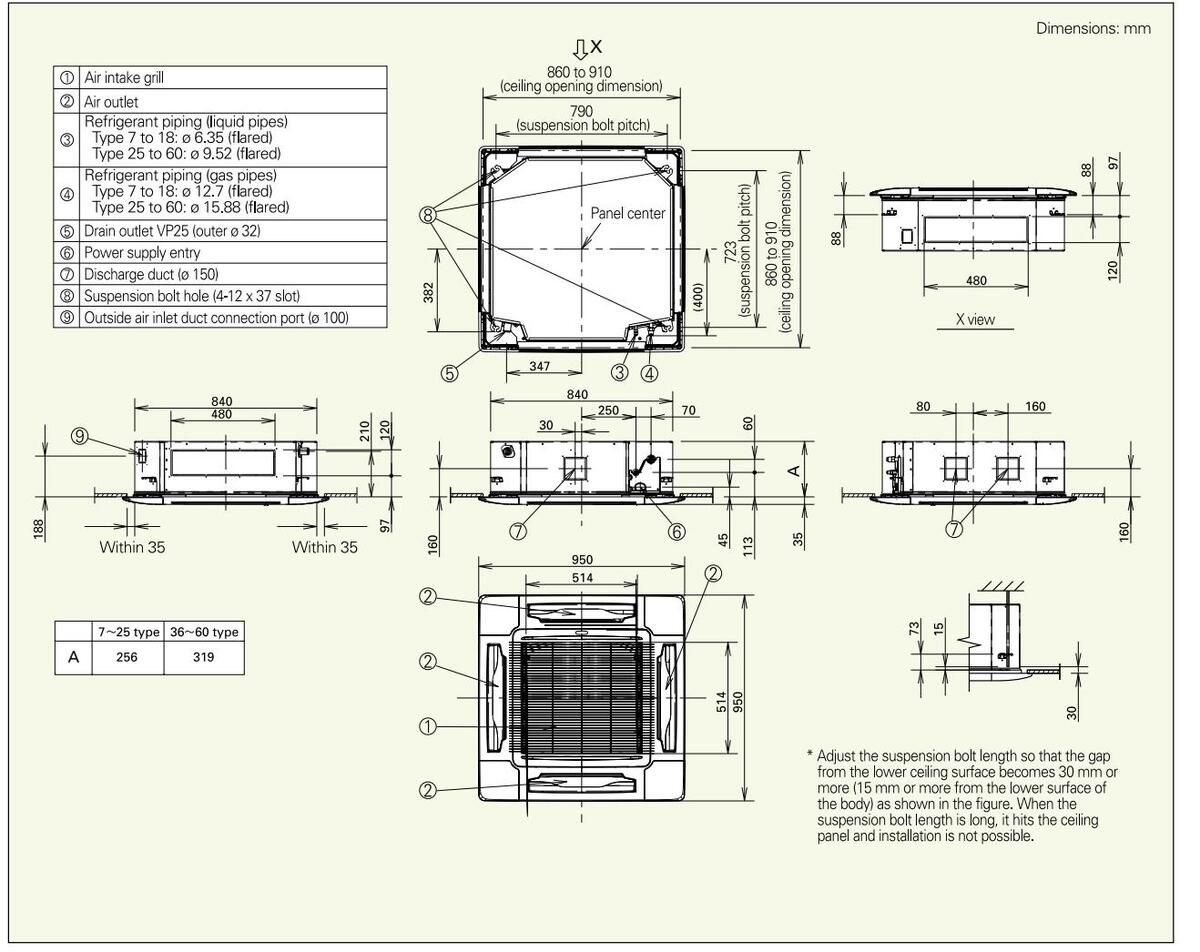
| Height mm 256 + <35> 3 | 319 + <35> | |||||||||
| Dimensions Width mm 840 <950> | ||||||||||
| Depth mm 840 <950> | ||||||||||
| Liquid (Flare) mm 6.35 9.52 | ||||||||||
| Piping connections Gas (Flare) mm 12.7 15.88 | ||||||||||
| Drain piping VP-25 | ||||||||||
| Net weight kg 21 + <4.5> 22 + <4.5> 26 + | kg 21 + <4.5> 22 + <4.5> 26 + <4.5> | |||||||||
lated conditions Cooling: Indoor air temperature 27°C DB/19°C WB, outdoor air temperature 35°C DB Heating: Indoor air temperature 20°C DB, outdoor air temperature 7°C DB/6°C WB
t are the values for the optional ceiling panel. Data subject to change without notice.
Dimensional data
Downloaded from www.Manualslib.com manuals search engine
SEMI-CONCEALED CASSETTE 4-WAY AIR DISCHARGE

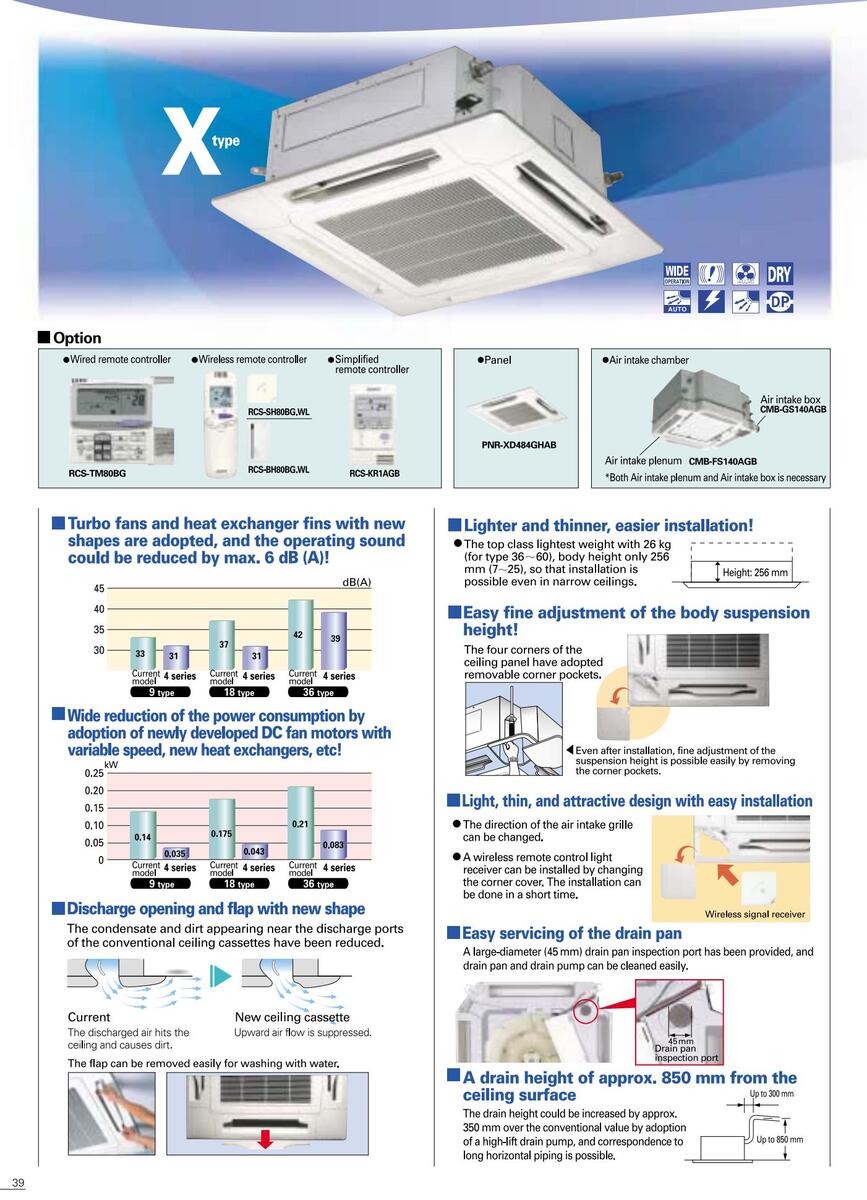
New dimensions 600 x 600 mm suitable for European under ceiling standards
Three-speed centrifugal fan
Anti-mould and anti-bacteria washable filters
Low operating sound

| Indoor un | its sp | ecificati | ons | |||||||||
|---|---|---|---|---|---|---|---|---|---|---|---|---|
| Model nam | e | (5 | SPW-) | XMR74EXH56B | XMR94EXH56B | XMR124EXH56B | XMR164EXH56B | XMR184EXH56B | ||||
| Power sour | ce | 22 | 20/230/240V, 1 phase-50 | Hz | ||||||||
| Cooling can | acity | kW | 2.2 | 2.8 | 3.6 | 4.5 | 5.6 | |||||
| cooming cap | acity | BTU/h | 7,500 | 9,600 | 15,000 | 19,000 | ||||||
| aoity | kW | 2.5 | 2.5 3.2 4.2 | 6.3 | ||||||||
| пеациу сар | acity | BTU/h | 8,500 | 11,000 | 14,000 | 17,000 | 21,000 | |||||
| Power input | Cooling | kW | 0.087/0.087/0.087 | |||||||||
| 1 ower input | Heating | kW | 0.087/0.087/0.087 | |||||||||
| Rupping an | noroc | Cooling | А | 0.41/0.41/0.41 | ||||||||
| Numing an | iperes | Heating | А | 0.41/0.41/0.41 | ||||||||
| Туре | Centrifugal fan | |||||||||||
| Fan motor | Airflow | / rate (H/M/L) | m³/min | 11.7/10/8.3 | 12.5/1 | 0.5/8.8 | ||||||
| Outpu | ıt | kW | 0.06 | 0.06 | ||||||||
| Power sound | d level ( | H/M/L) | dB(A) | 54/51/48 | 55/51/48 | |||||||
| Pressure sou | ind leve | el (H/M/L) | dB(A) | 43/40/37 | 44/4 | .0/37 | ||||||
| F | leight | mm | 296 | |||||||||
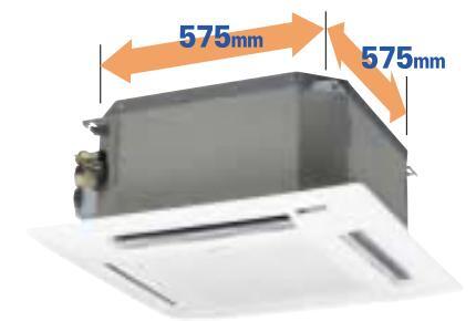
| Dimensions | ١ | Nidth | mm | 575 <730> | ||||||||
| 0 | Depth | mm | 575 <730> | |||||||||
| L | _iquid (Flare) | mm | 6.35 (1/4) | |||||||||
| Piping conne | Piping connections Gas (Flare) | mm | 12.7 (1/2) | |||||||||
| [ | Drain piping | VP-18 | ||||||||||
| Net weight | kg | 16.5 + <2.5> | 18 + | <2.5> | ||||||||
| 1.1 | ||||||||||||
ated conditions Cooling: Indoor air temperature 27°C DB/19°C WB, outdoor air temperature 35°C DB Heating: Indoor air temperature 20°C DB, outdoor air temperature 7°C DB/6°C WB
Dimensional data
Downloaded from www.Manualslib.com manuals search engine
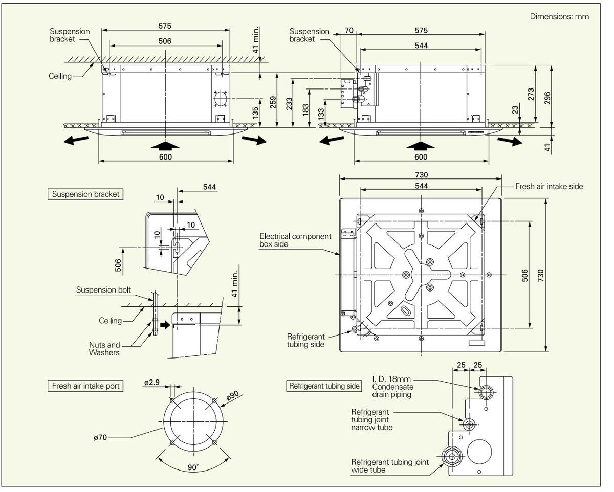
SEMI-CONCEALED CASSETTE 2-WAY AIR DISCHARGE
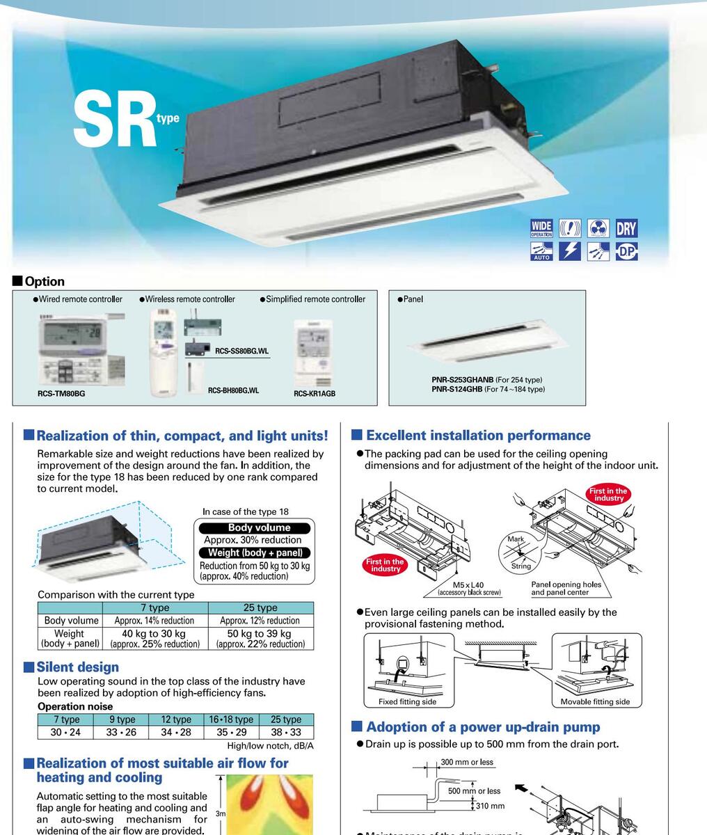
• Maintenance of the drain pump is possible from two sides, from the left (piping side) and from the inside of the unit.
Simple maintenance
The drain pan is equipped with site wiring and can be removed. The fan case has a split construction, and the fan motor and the fan can be removed easily when the lower case is removed.
| Indoor un | its sp | ecificati | ions | ||||||||||
|---|---|---|---|---|---|---|---|---|---|---|---|---|---|
| Model nam | e | ( | (SPW-) | SR74GXH56B | SR94GXH56B | SR124GXH56B | SR164GXH56B | SR184GXH56B | SR254GXH56B | ||||
| Power sour | ce | 220/230/240V, 1 phase-50, 60 Hz | |||||||||||
| Cooling con | o o ita / | kW | 2.2 | 2.8 | 3.6 | 4.5 | 5.6 | 7.3 | |||||
| Cooling cap | acity | BTU/h | 7,500 | 9,600 | 12,000 | 15,000 | 19,000 | 25,000 | |||||
| I leating and | kW | 2.5 | 3.2 | 4.2 | 5.0 6.3 | 5.0 6.3 | 8.0 | ||||||
| Heating cap | acity | BTU/h | 8,500 | 11,000 | 14,000 | 17,000 | 21,000 | 27,000 | |||||
| Power input | Cooling | kW | 0.086/0.090/0.095 | 0.086/0.092/0.097 | 0.088/0.093/0.099 | 0.091/0.0 | )97/0.103 | 0.135/0.145/0.154 | |||||
| rower input | Heating | kW | 0.055/0.058/0.062 | 0.055/0.060/0.064 | 0.057/0.061/0.066 | 0.060/0.0 | 065/0.070 | 0.100/0.109/0.117 | |||||
| Dunning | Cooling | А | 0.45/0.45/0.45 | 0.44/0.45/0.45 | 0.44/0.45/0.45 | 0.45/0. | 45/0.45 | 0.64/0.65/0.66 | |||||
| Running an | iperes | Heating | А | 0.29/0.29/0.30 | 0.28/0.29/0.30 | 0.28/0.29/0.30 | 0.29/0. | 29/0.30 | 0.46/0.48/0.49 | ||||
| Туре | Sirocco fan *1 | ||||||||||||
| Fan motor | Airflow | v rate (H/M/L) | m³/min | 8/7/6 | 9/8/7 | 9.6/8.6/7.6 | 11 | 19/16/14 | |||||
| Outpu | ıt | kW | 0.05 | ||||||||||
| Power sound | d level ( | H/M/L) | dB(A) | 40/38/35 | 44/40/37 | 45/42/39 | 46/4 | 14/40 | 49/46/44 | ||||
| Pressure sou | ind leve | el (H/M/L) | dB(A) | 30/27/24 | 33/29/26 | 34/31/28 | 35/3 | 33/29 | 38/35/33 | ||||
| ŀ | Height | mm | 350 + | - <8> | |||||||||
| Dimensions | 1 | Nidth | mm | 840 <1060> | 1140 <1360> | ||||||||
| [ | Depth | mm | 600 < | (680> | |||||||||
| Liquid (Flare) | ) mm | 6.35 | 9.52 | ||||||||||
| Piping conne | ctions ( | Gas (Flare) | mm | 12.7 | 15.88 | ||||||||
| Drain piping | 3 | VP-25 | |||||||||||
| Net weight kg | 23 + <7> 30 + <9> | ||||||||||||
| Ated conditions * The values in < > for external dimensions and net weight are the values | for the optional ceiling pane | ||||||||||||
Cooling: Indoor air temperature 27'C DB/19'C WB, outdoor air temperature 35'C DB Heating: Indoor air temperature 20'C DB, outdoor air temperature 7'C DB/6'C WB
* The values in < > for external dimensions and net weight are the values for the optional ceiling panel. Data subject to change without notice.
Dimensional data
Downloaded from www.Manualslib.com manuals search engine
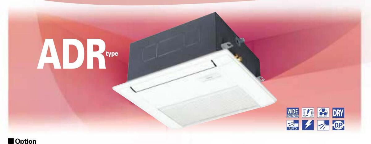
SEMI-CONCEALED CASSETTE 1-WAY AIR DISCHARGE
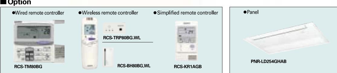
•Wired remote controller •Wireless remote controller •Simplified remote controller •Wired remote controller •Panel
Compact Size in the top class of the industry
The compact design keeps unit width and height to a minimum and delivers the industry's smallest panel width, giving you plenty of leeway in selecting
an installation space.

Lightweight Construction in the top class of the industry
Panel d
With a maximum unit weight of 8.5 kg, installation work is a snap.
Weight of Products (kg)
| Unit weight (including Panel) | ||||||||
|---|---|---|---|---|---|---|---|---|
| Туре | B type | Current model | ||||||
| 7 type | 17+(2.5) | 23+(3) | ||||||
| 9 type | 17+(2.5) | 23+(3) | ||||||
| 12 type | 17+(2.5) | 25+(3) | ||||||
Quiet Operation in the top class of the industry
With operating noise reduced by up to 3 dB(A) over existing models, the unit creates a quiet, comfortable room environment.
Operation noise dB(A)
| operation noise ab( | (Ingri/Low operation | |||
|---|---|---|---|---|
| Туре | B type | Current model | ||
| 7 type | 33 / 29 | 34 / 30 | ||
| 9 type | 33 / 29 | 34 / 30 | ||
| 12 type | 36 / 31 | 39 / 33 | ||
■ Quiet Operation in the top class of the industry
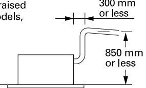
The drain height has been raised by 63 mm over existing models, so operation can be started from the ceiling and pipe layout design has greater
Auto Flap and Auto Swing Functions
The Auto Flap function lets you set the air direction by remote control, and the Auto Swing function delivers a uniform amount of air to every part of the room. What is more, the flap can be closed when the unit is not operating to keep dust from entering the room.
The hanging height of the unit can be easily adjusted
Adjustable covers are equipped on both sides of the ceiling panel so that the hanging height of the unit can be adjusted even after the panel has been installed.
Adjustable covers on both sides of panel
_____45
| nto opi | comcath | 0113 | ||||||
|---|---|---|---|---|---|---|---|---|
| Model nam | е | (S | SPW-) | ADR74GXH56B | ADR94GXH56B | ADR124GXH56B | ||
| Power source | e | 220/230/240V, 1 phase-50, 60 Hz | ||||||
| Cooling con | ooit ( | kW | 2.2 | 2.8 | 3.6 | |||
| Cooling cap | acity | BTU/h | 7,500 | 9,600 | 12,000 | |||
| Heating con | o o ita / | kW | 2.5 3.2 | 4.2 | ||||
| пеациу сара | acity | BTU/h | 8,500 | 11,000 | 14,000 | |||
| Powerinput | Power input Cooling kW | 0.060/0.0 | 061/0.063 | 0.064/0.064/0.067 | ||||
| Heating kW | kW | 0.037/0.0 | 037/0.038 | 0.039/0.039/0.04 | ||||
| Bunning amperes Cooling A | А | 0.24/0. | 23/0.22 | 0.25/0.24/0.24 | ||||
| Running am | Heating A | А | 0.16/0. | 0.17/0.17/0.17 | ||||
| Туре | Гуре | Sirocco fan *1 | ||||||
| Fan motor | Airflow | rate (H/M/L) | m³/min | 8/7/6 9/8/7 | ||||
| Output | t | kW | ||||||
| Power sound | l level (H | H/M/L) | dB(A) | 44/4 | 47/45/42 | |||
| Pressure sou | ind leve | I (H/M/L) | dB(A) | 33/3 | 1/29 | 36/34/31 | ||
| Н | leight | mm | 300 + <30> | |||||
| Dimensions | V | Vidth | mm | 600 <760> | ||||
| C | Depth | mm | 560 <620> | |||||
| L | iquid (Flare) | mm | 6.35 | |||||
| Piping connect | Piping connections Gas (Flare) | mm | 12.7 | |||||
| C | Drain piping | VP-25 | ||||||
| Net weight | kg | 17 + <2.5> | ||||||
| Bated conditions | * The values in < > for external dimensions and | I net weight are the values for the optional ceiling panel. | ||||||
fated conditions Cooling: Indoor air temperature 27'C DB/19'C WB, outdoor air temperature 35'C DB Heating: Indoor air temperature 20'C DB, outdoor air temperature 7'C DB/6'C WB
ne values in < > for external dimensions and net weight are the values for the optional ceiling panel. Data subject to change without notice.
Dimensional data
Indoor unito en olificatione
SEMI-CONCEALED SLIM CASSETTE
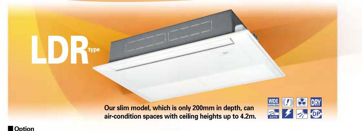
Top industrial capacity*1 to handle ceiling heights up to 4.2m
| Attained height/ceiling height based on fan motor speed setting (m) | ||||||||||
|---|---|---|---|---|---|---|---|---|---|---|
| *2 Indoor unit type | 9-type ~ | ~18-type | 25-type | |||||||
| Fan speed setting | Attained height | Ceiling height | Attained height | Ceiling height | ||||||
| Factory setting | 3.2 | 3.5 | 3.5 | 3.8 | ||||||
| High-ceiling setting | 3.9 | 4.2 | 3.9 | 4.2 | ||||||
| Ceiling-mounted installation 2.4 2.7 2.4 2.7 | ||||||||||
| *1 With one-direction type for high ceilings (current as of November 2004) | ||||||||||
*2 For setting method, refer to the installation instructions that came with the ceiling panel.
Lightweight, Compact and Quiet
With a full model change, all models are now the top industrial lightweight units*. And with all models having coordinated dimensions between the unit and the panel, multi-unit installations have a smart, attractive appearance. (* Current as of November 2004)
Product (unit + panel) weight (kg)
| Current model | New model | Reduction | |
|---|---|---|---|
| 9/12 type | 26+(8)kg | 21+(5.5)kg | 22% |
| 16/18 type | 27+(8)kg | 21+(5.5)kg | 24% |
| 25 type | 30+(9)kg | 22+(5.5)kg | 29% |
| Operating noise | [dB(A)] | (High/Low operation) |
|---|---|---|
| Current model | New model | |
| 9/12 type | 43/33 | 36/33 |
| 16 type | 44/35 | 36/34 |
| 18 type | 44/35 | 38/34 |
| 25 type | 46/36 | 45/36 |
With 3 types of air-blow systems, the units can be used in various ways.
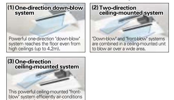
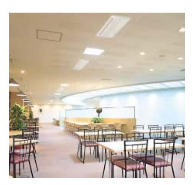
Smudge-free operation
Setting the flap in the smudge-free position suppresses soiling around the air outlet that is seen in conventional ceiling cassettes, so the ceiling stays clean at all times.
The hanging height of the unit can be easily adjusted.
The up-down position of the unit can be easily adjusted by simply removing the panel side covers, without having to remove the ceiling panel.
Separation distance from nearest obstacle

47
| Model nam | e | (S | SPW-) | LDR94GXH56B | LDR124GXH56B | LDR164GXH56B | LDR184GXH56B | LDR254GXH56B | |
|---|---|---|---|---|---|---|---|---|---|
| Power source | е | 220/2 | 230/240V, 1 phase-50, 6 | 0Hz | |||||
| Cooling cap | ocity | kW | 2.8 | 3.6 | 4.5 | 5.6 | 7.3 | ||
| acity | BTU/h | 9,600 | 12,000 | 15,000 | 19,000 | 25,000 | |||
| Heating con | Heating capacity | kW | 3.2 | 4.2 | 5.0 | 6.3 | 8.0 | ||
| Heating capacity | BTU/h | 11,000 | 14,000 | 17,000 | 21,000 | 27,000 | |||
| Power input Cooling kW | kW | 0.050/0.051/0.052 | 0.058/0.060/0.061 | 0.086/0.087/0.089 | |||||
| Heating kW | kW | 0.039/0.040/0.042 | 0.046/0.048/0.049 | 0.075/0.076/0.077 | |||||
| Rupping amparea Cooling A | A | 0.40/0.39/0.39 | 0.46/0.46/0.46 | 0.71/0.70/0.69 | |||||
| Running amperes Heating | А | 0.36/0.35/0.35 | 0.42/0.41/0.41 | 0.66/0.65/0.63 | |||||
| Туре | Туре | Sirocco fan *2 | |||||||
| Fan motor | Airflow | flow rate (H/M/L) m³/min | 12/ | 10/9 | 12/11/10 | 13/11.5/10 | 18/15/13 | ||
| Output | out kW | 0.05 | |||||||
| Power sound | level (F | H/M/L) | dB(A) | 47/4 | 5/44 | 47/46/45 | 49/47/45 | 56/51/47 | |
| Pressure sou | nd leve | I (H/M/L) | dB(A) | 36/3 | 34/33 | 36/35/34 | 38/36/34 | 45/40/36 | |
| Н | leight | mm | 200+<20> | ||||||
| Dimensions | V | Vidth | mm | 1,000 <1,230> | |||||
| D | )epth | mm | 710 <800> | ||||||
| Liquid (Flare) mm | mm | 6.3 | 35 | 9.52 | |||||
| Piping connect | Piping connections Gas | mm | 12 | .7 | 15.88 | ||||
| Drain p | VP-25 | • | |||||||
| Net weight kg | kg | 21+<5.5> 22+<5.5> | |||||||
| Rated conditions | * The values | in < > for external dimensions | and net weight are the values | for the optional ceiling papel | |||||
fated conditions Cooling: Indoor air temperature 27'C DB/19'C WB, outdoor air temperature 35'C DB Heating: Indoor air temperature 20'C DB, outdoor air temperature 7'C DB/6'C WB
* The values in < > for external dimensions and net weight are the values for the optional ceiling panel * The values in ( ) for air flow rate and operating sound are for use of the accessory cable.
Data subject to change without notice.
Dimensional data
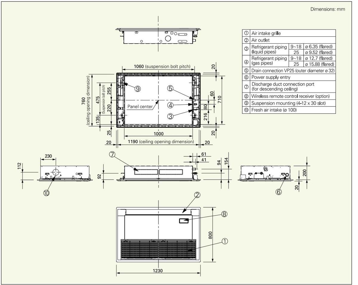
Indoor units specifications
_48
CONCEALED DUCT
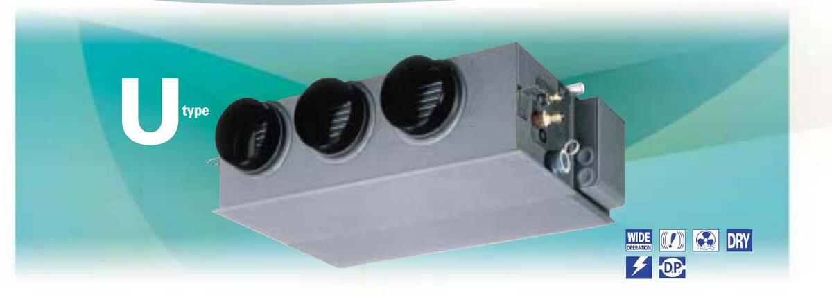
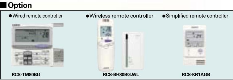
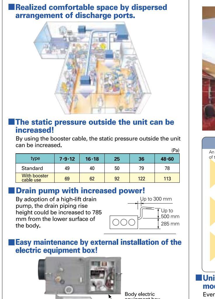
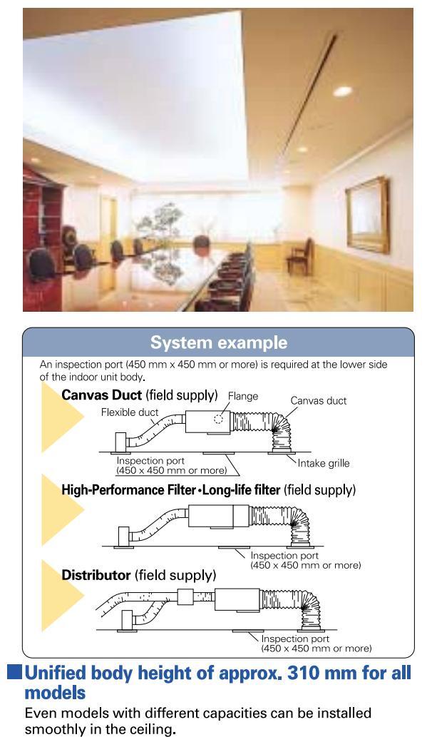
| ndoor | units | s speci | ficat | ions | ||||||||
|---|---|---|---|---|---|---|---|---|---|---|---|---|
| Model r | name | (SF | PW-) | U075XH | U095XH | U125XH | U165XH | U185XH | U255XH | U365XH | U485XH | U605XH |
| Power s | ource | . 2 | 20/230/240V, 1 | l phase-50, 60 | Hz | |||||||
| Cooling | 00000 | it. | kW | 2.2 | 2.8 | 3.6 | 4.5 | 5.6 | 7.3 | 10.6 | 14.0 | 16.0 |
| coomig | capac | ity | BTU/h | 7,500 | 9,600 | 12,000 | 15,000 | 19,000 | 25,000 | 36,000 | 47,800 | 54,600 |
| Heating | it. | kW | 2.5 | 3.2 | 4.2 | 5.0 | 6.3 | 8.0 | 11.4 | 16.0 | 18.0 | |
| B. | BTU/h | 8,500 | 11,000 | 14,000 | 17,000 | 21,000 | 27,000 | 39,000 | 54,600 | 61,400 | ||
| Power input Cooling kW | kW | 0 | .094/0.100/0.106 | 6 | 0.096/0 | .102/0.109 | 0.180/0.195/0.210 | 0.312/0.327/0.342 | 0.308/0.3 | 25/0.341 | ||
| Heating k | kW | 0 | .082/0.088/0.094 | 1 | 0.084/0 | .090/0.097 | 0.168/0.183/0.198 | 0.300/0.315/0.330 | 0.296/0.3 | 313/0.329 | ||
| Running | I | Cooling | А | 0.45/0.46/0.47 | 0.44/0 | .45/0.46 | 0.83/0.86/0.89 | 1 44/1 45/1 46 | 1.42/1. | 43/1.44 | ||
| amperes Heating | Heating | А | 0.40/0.41/0.42 | 0.39/0.40/0.41 | 0.78/0.81/0.84 | 1.39/1.40/1.41 | 1.36/1.37/1.38 | |||||
| Туре | Sirocco fan * | Sirocco fan *2 | Sirocco fan *3 | |||||||||
| Fan motor | Airflow I | v rate (H/M/L) m³/min | 10/8.5/7 | 12/ | 10.5/9 | 18/15/13 | 30/26/21 | 33/3 | 0/25 | |||
| Outpu | ıt | kW | 0.05 | 0.07 | 0. | 14 | ||||||
| Extern |
al static
ire |
Pa | 49(69) | 40(62) | 50(92) | 79(122) | 78( | 113) | ||||
| Power sound | d level (H | /M/L) | dB(A) | 40/37/33 | 41/ | 39/36 | 45/41/38 | 49/44/42 | 51/4 | 8/44 | ||
| Pressure sou | ind level | (H/M/L) | dB(A) | (32)/29/26/22 | (33)/3 | 0/28/25 | (38)/34/30/27 | (42)/38/33/31 | (44)/4( | )/37/33 | ||
| Heig | ht | mm | 3 | 310 | ||||||||
| Dimension | s Widt | :h | mm | 700 | 1000 | 1480 | ||||||
| Dept | th | mm | 6 | 630 | ||||||||
| Liquid (Flare) | mm | 6.35 | 9.5 | 52 | ||||||||
| Piping | Gas | (Flare) | mm | 12.7 | 15. | 88 | ||||||
| connections | Drai | n piping | VI | - 25 | ||||||||
| Net weig | ght | kg | 24 | 25 | 32 | 47 | ||||||
lated conditions Cooling: Indoor air temperature 27°C DB/19°C WB, outdoor air temperature 35°C DB Heating: Indoor air temperature 20°C DB, outdoor air temperature 7°C DB/6°C WB
e values in ( ) for the external static pressure and operating sound are for use of booster cable. Data subject to change without notice.
Dimensional data
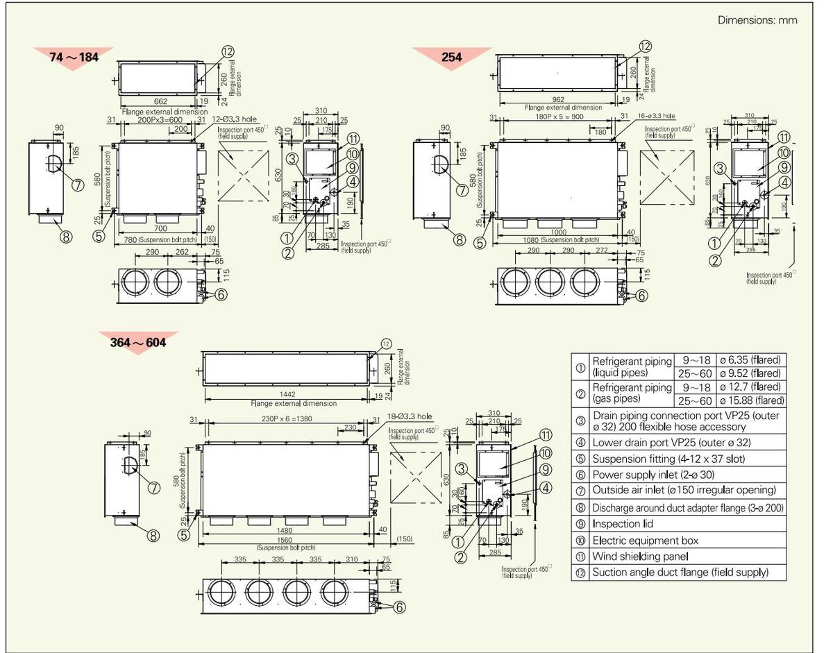
CONCEALED-RECTANGLE DUCT TYPE
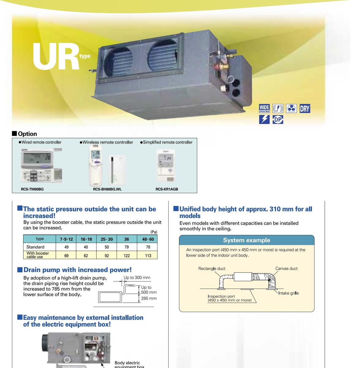
51
Anti-mould washable filters included
| Indoo | r units s | specifi | cations | |||||||||
|---|---|---|---|---|---|---|---|---|---|---|---|---|
| Model | name | (SPW-) | U075SXHT | U095SXHT | U125SXHT | U165SXHT | U185SXHT | U255SXHT | U305SXHT | U365SXHT | U485SXHT | U605SXHT |
| Power | source |
,
, |
220/230/240V, | 1 phase-50H: |
Z |
|||||||
| Cooling | kW | 2.2 | 2.8 | 3.6 | 4.5 | 5.6 | 7.3 | 9.0 | 10.6 | 14.0 | 16.0 | |
| Coonné | y capacity | BTU/h | 7,500 | 9,600 | 12,000 | 15,000 | 19,000 | 25,000 | 30,000 | 36,000 | 47,800 | 54,600 |
| Heating | Heating capacity | 2.5 | 3.2 | 4.2 | 5.0 | 6.3 | 8.0 | 10.0 | 11.4 | 16.0 | 18.0 | |
| пеаци | g capacity | BTU/h | 8,500 | 11,000 | 14,000 | 17,000 | 21,000 | 27,000 | 34,000 | 39,000 | 54,600 | 61,400 |
| Power | Cooling | kW | 0. | .094 / 0.100 / 0.10 | )6 | 0.109/0.102/0.096 | 0.096/0.102/0.109 | 0.180/0.195/0.210 | 0.187/0.203/0.219 | 0.312/0.327/0.342 | 0.308/0.3 | 325/0.341 |
| input | Heating | kW | 0. | .082 / 0.088 / 0.09 | 94 | 0.097/0.090/0.084 | 0.084/0.090/0.097 | 0.168/0.183/0.198 | 0.176/0.191/0.207 | 0.300/0.315/0.330 | 0.296/0.3 | 313 / 0.329 |
| Running | Cooling | А | 0.45/0.46/0.47 | 0.46/0.45/0.44 | 0.44/0.45/0.46 | 0.83/0.86/0.89 | 0.88/0.91/0.94 | 1.44/1.45/1.46 | 1.42/1. | 43 / 1.44 | ||
| amperes | amperes Heating | 0.40/0.41/0.42 | 0.41/0.40/0.39 | 0.39/0.40/0.41 | 0.78/0.81/0.84 0.84/0.87/0.90 | 1.39/1.40/1.41 | 1.36/1.37/1.38 | |||||
| I | ype | Sirocco fan * | l | Sirocco | fan *2 | Sirocco fan *3 | 3 | |||||
| Fan 🦯 | irflow rate (H/N | 1/L) m³/min | 10/8.5/7 | 12/ | 10.5/9 | 18/15/13 | 20/17/14 | 30/26/21 | 33/3 | 0/25 | ||
| motor | Dutput | kW | 0.05 | 07 | 0.14 | |||||||
| E | xternal stat | ic Pa | 49(69) | 40(62) | 92) | 79(122) | 78( | 113) | ||||
| Power soun | d level (H/M/L) | dB(A) | 40 / 37 / 33 | 41 / | 39/36 | 45/41/38 | 45 / 41 / 38 | 49 / 44 / 42 | 51/4 | 18 / 44 | ||
| Pressure so | und level (H/M/L | ) dB(A) | (33) / 29 / 26 / 22 | (33) / 3 | 80/28/25 | (38)/34/30/27 | (38)/34/30/27 | (42)/38/33/31 | (44) / 40 | / 37 / 33 | ||
| Height | mm | 37 | 10 | |||||||||
| Dimension | ns Width | mm | 700 | 10 | 00 | 1480 | ||||||
| Depth | mm | 63 | 30 | |||||||||
| Dining | Liquid (Fla | re) mm | 6.35 (1/4) | 9.52 (3/8) | ||||||||
| connectio | ns Gas (Flare) | mm | 12.7 (1/2) | 15.88 (5/8) | ||||||||
| Drain pipi | ng | VP | 25 | |||||||||
| Net weig | nt | kg | 24 | 25 | 3 | 2 | 47 | |||||
| Rated cond | * The values in ( ) for the external static pressure and operating sound are for use of booster cable. | oster cable. | ||||||||||
Tated conditions Cobling: Indoor air temperature 27 °C DB/19°C WB, outdoor air temperature 35 °C DB Heating: Indoor air temperature 20 °C DB, outdoor air temperature 7 °C DB/6°C WB
Data subject to change without notice.
Dimensional data
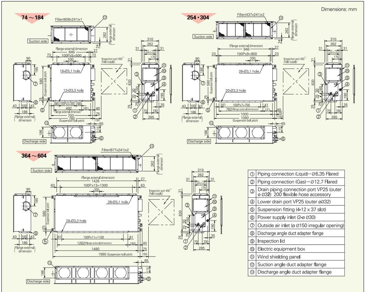
CONCEALED-DUCT

| Indoor u | units sp | ecificati | ons | ||||||
|---|---|---|---|---|---|---|---|---|---|
| Model na | ame | ($ | SPW-) | US075XH | US095XH | US125XH | US165XH | US185XH | |
| Power so | ource | 220 | /230/240V, 1 phase-50, 6 | i0Hz | |||||
| Cooling | onooit ( | kW | 2.2 | 2.8 | 3.6 | 4.5 | 5.6 | ||
| cooling c | арасну | BTU/h | 7,500 | 9,600 | 12,000 | 15,000 | 19,000 | ||
| Heating | onooit / | kW | 2.5 | 3.2 | 4.2 | 5.0 | 6.3 | ||
| пеаціну с | арасну | BTU/h | 8,500 | 11,000 | 14,000 | 17,000 | 21,000 | ||
| Powerinn | + | Cooling | kW | 0.036 / 0.036 / 0.036 | 0.040 / 0.040 / 0.040 | 0.042 / 0.042 / 0.042 | 0.049/0.049/0.049 | 0.064 / 0.064 / 0.064 | |
| Hea | Heating | kW | 0.026/0.026/0.026 | 0.030 / 0.030 / 0.030 | 0.032 / 0.032 / 0.032 | 0.039 / 0.039 / 0.039 | 0.054 / 0.054 / 0.054 | ||
| Rupping | Running amperes | А | 0.26/0.26/0.26 | 0.30/0.30/0.30 | 0.31/0.31/0.31 | 0.37 / 0.37 / 0.37 | 0.48/0.48/0.48 | ||
| Running | А | 0.23/0.23/0.23 | 0.27 / 0.27 / 0.27 | 0.28/0.28/0.28 | 0.34/0.34/0.34 | 0.45/0.45/0.45 | |||
| Туре | Sirocco fan | ||||||||
| Fan motor | Airflow ra | flow rate (H/M/L) m 3 /n | 8/7/6 | 8.5/7.5/6.5 | 9/8/7 | 10.5/9.5/8 | 12.5/11.5/10 | ||
| 1 difficitor | Output | kW | 0.05 | ||||||
| External s | tatic pressure | Ра | 10 - 30 | 15 - 30 | 15 - 40 | ||||
| Power so | und level | (H/M/L) | dB(A) | 43 / 42 / 40 | 45 / 44 / 42 | 47 / 45 / 43 | 49 / 47 / 45 | 52 / 50 / 48 | |
| Pressure | sound lev | el (H/M/L) | dB(A) | 28 / 27 / 25 | 30 / 29 / 27 | 32 / 30 / 28 | 34 / 32 / 30 | 35 / 33 / 31 | |
| Height | mm | 200 | |||||||
| Dimensio | ns | Width | mm | 750 | |||||
| Depth | mm | 640 | |||||||
| Liquid (Flare) | mm | 6.35 (1/4) | |||||||
| Piping cor | nnections | Gas (Flare) | mm | 12.7 (1/2) | |||||
| Drain piping | VP-20 | ||||||||
| Net weig | Net weight kg | 19 | |||||||
ated conditions Cooling: Indoor air temperature 27°C DB/19°C WB, outdoor air temperature 35°C DB Heating: Indoor air temperature 20°C DB, outdoor air temperature 7°C DB/6°C WB
Data subject to change without notice.

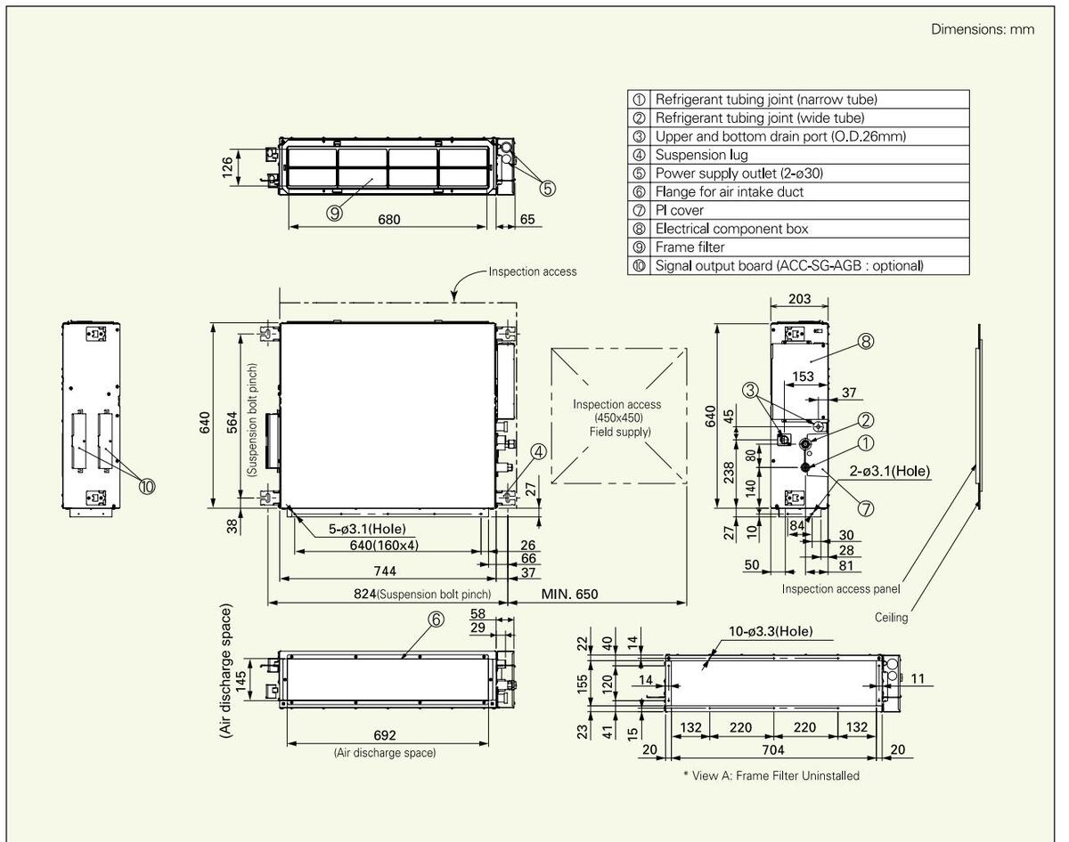
FLOOR/CEILING SLIM CONCEALED DUCT
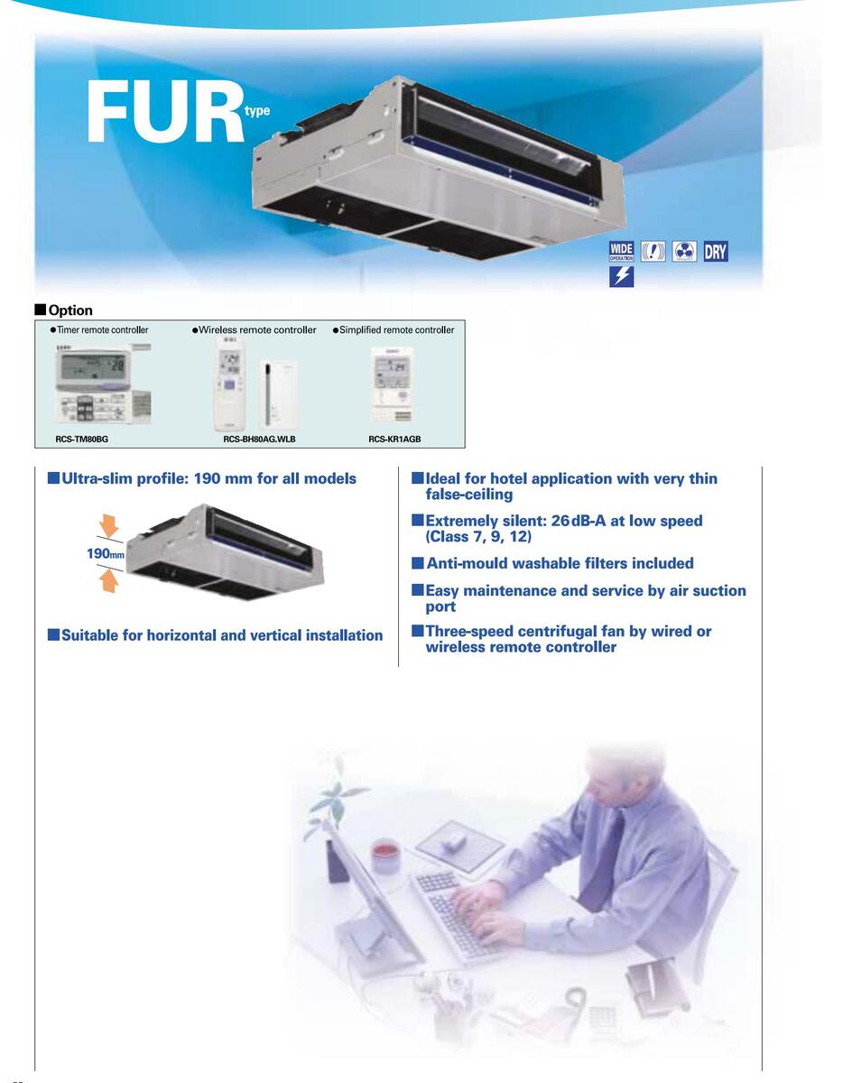
| Model na | me | (SPW-) | FUR74EXH56B | FUR94EXH56B | FUR124EXH56B | FUR164EXH56B | FUR184EXH56B | FUR224EXH56B | |||
|---|---|---|---|---|---|---|---|---|---|---|---|
| Power sou | urce | 220/230/240V, | 1 phase-50 Hz | ||||||||
| Casling of | kW | 2.2 | 2.8 | 3.6 | 4.5 | 5.6 | 6.4 | ||||
| Cooling ca | арасну | BTU/h | 7,500 | 9,600 | 12,000 | 15,000 | 19,000 | 22,000 | |||
| kW | 2.5 | 3.2 | 4.2 | 5.0 | 6.3 | 7.0 | |||||
| BTU/h | 8,500 | 11,000 | 14,000 | 17,000 | 21,000 | 24,000 | |||||
| Cooling kW | kW | 0.037/0.037/0.037 | 0.065/0.0 | 065/0.065 | 0.088/0.088/0.088 | ||||||
| Power Input Heating kW | kW | 0.037/0.037/0.037 | 0.065/0.0 | 065/0.065 | 0.088/0.088/0.088 | ||||||
| Bunning | Cooling | А | 0.17/0.17/0.17 | 0.29/0. | 29/0.29 | 0.41/0.41/0.41 | |||||
| Running amperes Heating A | А | 0.17/0.17/0.17 | 0.29/0.29/0.29 0.41/0.41/0.41 | ||||||||
| Туре | Sirocco fan | ||||||||||
| Fan motor | Airflow rat | te (H/M/L) | m³/min | 7.8/6.3/5.6 | 10.3 | 11.3/10/8.7 | |||||
| Output | kW | 0.04 | 0. | 0.09 | |||||||
| External st | atic pressure | Ра | 7.5 | ||||||||
| Power sou | ınd level ( | H/M/L) | dB(A) | 48/41/37 | 56/5 | 60/56/51 | |||||
| Pressure s | ound leve | el (H/M/L) | dB(A) | 37/30/26 | 45/41/33 49/45/40 | ||||||
| ŀ | Height | mm | 190 | ||||||||
| Dimension | ns | Nidth | mm | 89 | 90 | ||||||
| Depth mm | mm | 6 | 14 | ||||||||
| Liquid (Flare) mn | mm | 6.35 | (1/4) | ||||||||
| Piping connections | Gas (Flare) | mm | 12.7 | (1/2) | |||||||
| Drain piping | VP | -26 | |||||||||
| Net weight kg | kg | 2 | 5 | ||||||||
Indeer unite en esificatione
Rated conditions Cooling: Indoor air temperature 27'C DB/19'C WB, outdoor air temperature 35'C DB Heating: Indoor air temperature 20'C DB, outdoor air temperature 7'C DB/6'C WB
* The values in ( ) for the external static pressure and operating sound are for use of booster cable. Data subject to change without notice.
Dimensional data
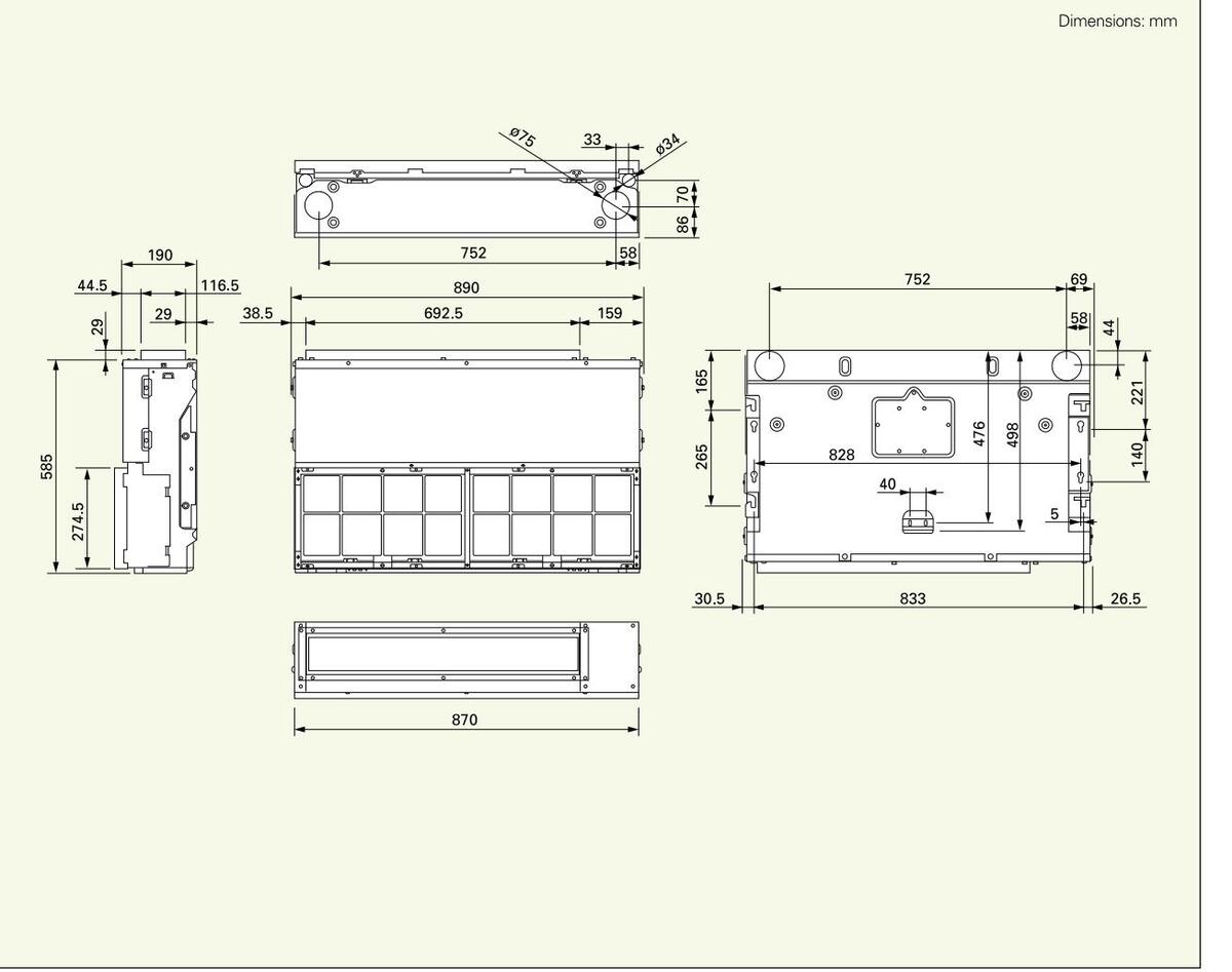
56
CONCEALED DUCT

| Model n | ame | (SPW-) | UMR74EXH56B | UMR94EXH56B | UMR124EXH56B | UMR164EXH56B | UMR184EXH56B | UMR224EXH56B | ||||
|---|---|---|---|---|---|---|---|---|---|---|---|---|
| Power sc | ource | 220/230/240V, 1 phase-50 Hz | ||||||||||
| Casling | kW | 2.2 2.8 3.6 | 4.5 | 5.6 | 6.4 | |||||||
| BTU/h | 7,500 | 9,600 | 12,000 | 15,000 | 19,000 | 22,000 | ||||||
| 11 | kW | 2.5 | 3.2 | 4.2 | 5.0 | 6.3 | 7.0 | |||||
| Heating c | сараситу | BTU/h | 8,500 | 11,000 | 14,000 | 17,000 | 21,000 | 24,000 | ||||
| D | Cooling | kW | 0.11/0.11/0.11 | 0.138/0.1 | 138/0.138 | 0.136/0.136/0.136 | ||||||
| Power inp | ut | Heating | kW | 0.11/0.11/0.11 | 0.138/0.1 | 138/0.138 | 0.136/0.136/0.136 | |||||
| Cooling | Cooling | А | 0.45/0.45/0.45 | 0.60/0. | 60/0.60 | 0.57/0.57/0.57 | ||||||
| Running | amperes | Heating | А | 0.45/0.45/0.45 | 0.60/0.60/0.60 | 0.57/0.57/0.57 | ||||||
| Ту | Туре | Sirocco fan | ||||||||||
| Fan motor | Airflow rat | e (H/M/L) | m³/min | 10/8.5/7.3 | 14 . 6/1 | 10/6.7 | 16.7/11.7/10 | |||||
| 1 an motor | Output | kW | 0.11 | 0.14 | ||||||||
| External st | atic pressure | Ра | 4 | 19 | ||||||||
| Power so | und level ( | H/M/L) | dB(A) | 54/52/49 | 54/- | 57/49/46 | ||||||
| Pressure | sound leve | el (H/M/L) | dB(A) | 43/41/38 | 43/3 | 36/31 | 46/38/35 | |||||
| leight | mm | 20 | 66 | |||||||||
| Dimensio | ns 👌 | Nidth | mm | 852 | 1,058 | |||||||
| 1 | Depth | mm | 5 | 72 | ||||||||
| Liqu | _iquid (Flare) | mm | 6.35 | (1/4) | ||||||||
| Piping connections | Gas (Flare) | mm | 12.7 | (1/2) | ||||||||
| Drain piping | VP | -18 | ||||||||||
| Net weight kg | ka | 30 35 | ||||||||||
Tated conditions Cooling: Indoor air temperature 27°C DB/19°C WB, outdoor air temperature 35°C DB Heating: Indoor air temperature 20°C DB, outdoor air temperature 7°C DB/6°C WB
perating sound are for use of booster cable. Data subject to change without notice.
nensional data
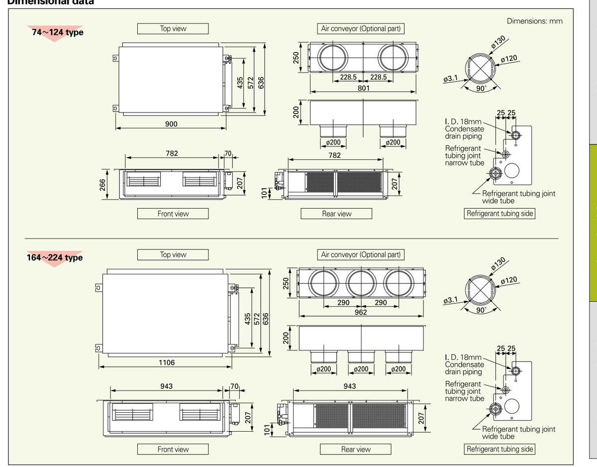
Downloaded from www.Manualslib.com manuals search engine
CONCEALED-DUCT HIGH-STATIC PRESSURE


High static pressure, low-noise design
Embedded ceiling type with high static pressure and excellent low operating sound features. As the discharge port also can be set freely, it is suitable for the office space.
Rap valve kit
Except for use as a single system, two rap valve kits are required for each unit for the type 76 and the type 96.
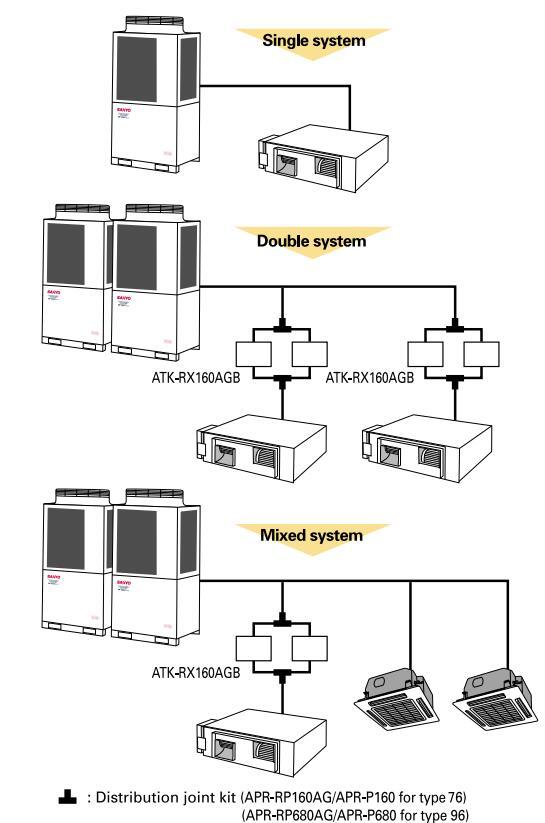
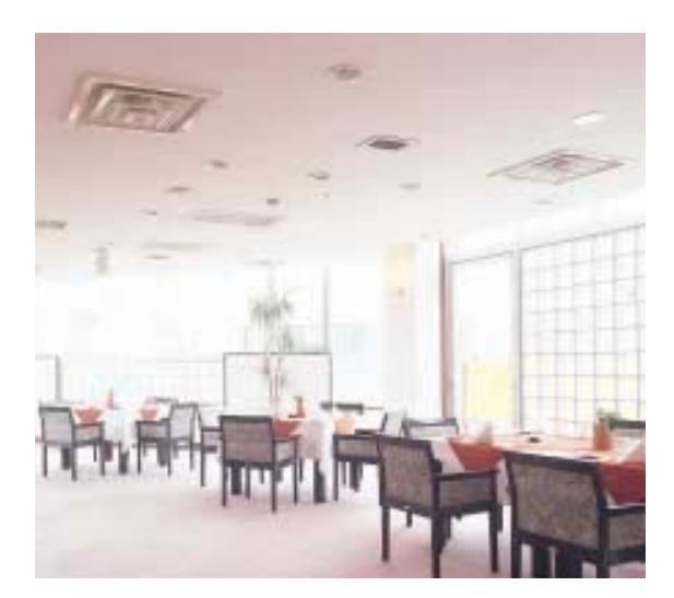
•"Short duct" use of the type DR
When the type DR is used with a short duct (duct length of 4 to 5 m, external static pressure around 49 Pa (5 mm Aq)), the air volume and the operating sound maybe too large and an air volume adjustment damper or similar should be installed. (The external static pressure for this model is 147 Pa (15 mm Aq) or more.) In such a case, we recommend that you check use of the type UR.
_____59
| Model na | ame | (S | PW-) | DR254GXH56B | DR364GXH56B | DR484GXH56B | DR764GXH56B | DR964GXH56B |
|---|---|---|---|---|---|---|---|---|
| Power so | urce | 220, |
/
230/240V, 1 phase-50, 6 |
0Hz | ||||
| Cooling o | apacity | kW | 7.3 | 10.6 | 14.0 | 22.4 | 28.0 | |
| cooling c | арасну | BTU/h | 25,000 | 36,000 | 47,800 | 76,400 | 95,500 | |
| kW | 8.0 | 11.4 | 16.0 | 25.0 | 31.5 | |||
| BTU/h | 27,000 | 39,000 | 54,600 | 85,300 | 107,500 | |||
| Power inn | ut | Cooling | kW | 0.480/0.505/0.530 | 0.520/0.545/0.570 | 0.600/0.660/0.710 | 0.870/0.900/0.930 | 1.270/1.330/1.390 |
| owerinp | ut | Heating | kW | 0.480/0.505/0.530 | 0.520/0.545/0.570 | 0.600/0.660/0.710 | 0.870/0.900/0.930 | 1.270/1.330/1.390 |
| Running amperes H | Cooling | A | 2.29/2.30/2.31 | 2.46/2.46/2.47 | 2.80/2.90/3.00 | 4.05/4.06/4.07 | 6.04/6.06/6.07 | |
| Heating | A | 2.29/2.30/2.31 | 2.46/2.46/2.47 | 2.80/2.90/3.00 | 4.05/4.06/4.07 | 6.04/6.06/6.07 | ||
| Тур | Туре | Sirocco fan *1 | Sirocco | fan *2 | ||||
| an motor | Airflow ra | Airflow rate (H/M/L) | 23/22/21 | 30/28/25 | 36/35/33 | 56/53.1/49.6 | 72/70/66 | |
| anniotor | Output | kW | 0.2 | 0.35 | 0.2*2 | 0.4*2 | ||
| External s | tatic pressure | Ра | 186 | 176 | 167 | 176 | 216 | |
| Power sou | und level | (H/M/L) | dB(A) | 55/54/53 | 56/55/53 | 58/57/55 | 59/58/57 | 62/61/60 |
| Pressure | sound lev | el (H/M/L) | dB(A) | 44/43/42 | 45/44/42 | 47/46/44 | 48/47/46 | 51/50/49 |
| Height | mm | 42 | 20 | 450 | 46 | 67 | ||
| Dimensio | ns | Width | mm | 1065 | 14 | 28 | ||
| [ | Depth | mm | 620 | 12 | 30 | |||
| Liquid (Flare) | mm | 9.52 | ||||||
| Piping connections G | Gas (Flare) | mm | 15.88 | 19.05 | 22.22 | |||
| Drain | Drain piping | VP-25 | ||||||
| Net weight kg | kg | 47 | 50 | 54 | 110 | 120 | ||
ated conditions Cooling: Indoor air temperature 27°C DB/19°C WB, outdoor air temperature 35°C DB Heating: Indoor air temperature 20°C DB, outdoor air temperature 7°C DB/6°C WB
Dimensional data
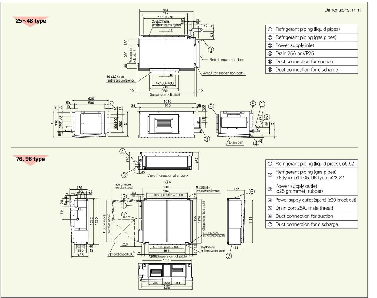
Downloaded from www.Manualslib.com manuals search engine
CEILING MOUNTED UNITS

| Indoor un | door units specifications | |||||||||||
|---|---|---|---|---|---|---|---|---|---|---|---|---|
| Model nam | е | (S | SPW-) | T125XH | T165XH | T185XH | T255XH | T365XH | T485XH | |||
| Power source | e | 220/230/240V, 1 | phase-50, 60 Hz | |||||||||
| Cooling can | acity | kW | 3.6 | 3.6 4.5 | 7.3 | 10.6 | 14.0 | |||||
| cooling capacity | BTU/h | 12,000 | 15,000 | 19,000 | 25,000 | 36,000 | 47,800 | |||||
| Leating con | kW | 4.2 | 5.0 | 6.3 | 8.0 | 11.4 | 16.0 | |||||
| acity | BTU/h | 14,000 | 17,000 | 21,000 | 27,000 | 39,000 | 54,600 | |||||
| Power input | Power input Cooling kW | kW | 0.028/0.0 | 29/0.029 | 0.031/0.032/0.032 | 0.043/0.043/0.044 | 0.073/0.074/0.075 | 0.085/0.086/0.088 | ||||
| i ower input | Heating kW | kW | 0.028/0.0 | 28/0.029 | 0.031/0.031/0.032 | 0.042/0.042/0.043 | 0.072/0.073/0.074 | 0.084/0.085/0.086 | ||||
| Dunning on | Cooling | А | 0.26/0. | 24/0.23 | 0.28/0.26/0.24 | 0.38/0.35/0.33 | 0.62/0.57/0.53 | 0.69/0.63/0.60 | ||||
| peres | Heating | A | 0.26/0. | 24/0.23 | 0.28/0.26/0.25 | 0.38/0.35/0.34 | 0.62/0.57/0.55 | 0.69/0.63/0.62 | ||||
| Туре | Sirocco fan *2 | Sirocco fan *3 | Sirocco far | ו *4 | ||||||||
| Fan motor | Airflow | / rate (H/M/L) | m³/min | 12/10/9 | 13/* | 11/9 | 18.5/15/14 | 27.5/23/20 | 30/26/22 | |||
| Outpu | t | kW | 0.03 | 0.08 | ||||||||
| Power sound | level ( | H/M/L) | dB(A) | 46/43/41 | 47/4 | 4/41 | 49/47/44 | 52/49/46 | 54/51/48 | |||
| Pressure sou | nd leve | el (H/M/L) | dB(A) | 35/32/30 | 36/3 | 3/30 | 38/36/33 | 41/38/35 | 43/40/37 | |||
| ŀ | leight | mm | 2 | 10 | ||||||||
| Dimensions | ٧ | Nidth | mm | 910 | 1180 | 15 | 95 | |||||
| Depth r | mm | 68 | 30 | |||||||||
| L | iquid (Flare) | mm | 6.35 | 9.52 | ||||||||
| Piping conne | ctions | Gas (Flare) | mm | 12.7 | 15.88 | |||||||
| Drain piping | VP | /P-20 | ||||||||||
| Net weight | Net weight kg | 21 | 25 | 3 | 3 | |||||||
ront
10 9
250 or mo
Dimensional data
tated conditions Cooling: Indoor air temperature 27°C DB/19°C WB, outdoor air temperature 35°C DB Heating: Indoor air temperature 20°C DB, outdoor air temperature 7°C DB/6°C WB
Data subject to change without notice.
Dimensions: mm

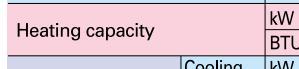

62
FLOOR/CEILING MOUNTED UNITS
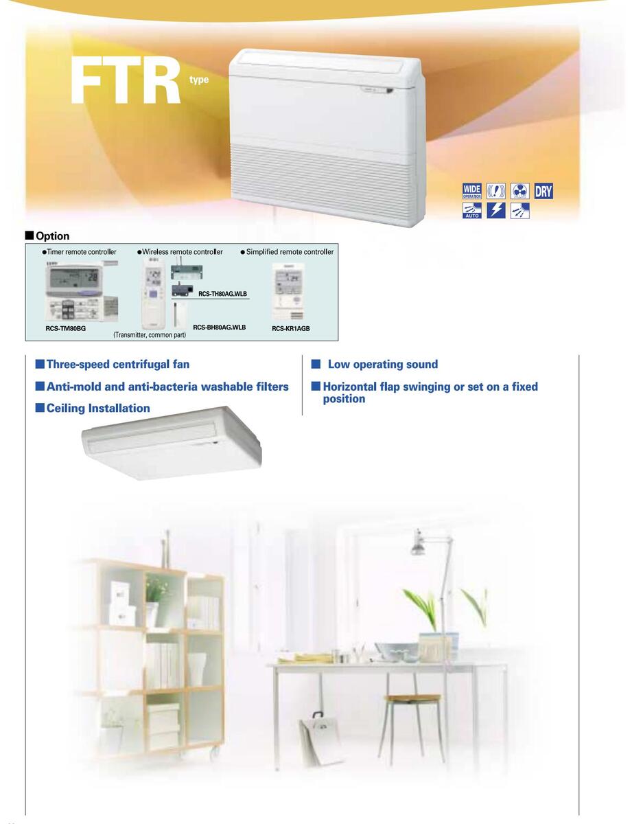
| 10 50 | oomoath | 0115 | |||||||||
|---|---|---|---|---|---|---|---|---|---|---|---|
| Model nam | е | ( | SPW-) | FTR74EXH56B | FTR94EXH56B | FTR124EXH56B | FTR164EXH56B | FTR184EXH56B | FTR224EXH56B | ||
| Power source | e | 220/230/240V, | 1 phase-50 Hz | ase-50 Hz | |||||||
| Coolin a constitu | kW | 2.2 | 2.8 | 3.6 | 4.5 | 5.6 | 6.4 | ||||
| Cooling capa | acity | BTU/h | 7,500 | 9,600 | 12,000 |
20/230/240V, 1 phase-50 Hz
3.6 4.5 5.6 6.4 12,000 15,000 19,000 22,000 4.2 5.0 6.3 7.0 14,000 17,000 21,000 24,000 0.88/0.88/0.88 0.88/0.88/0.88 0.88/0.88/0.88 0.41/0.41/0.41 0.41/0.41/0.41 Sirocco fan 12/10.8/9.7 15/13.5/12 0.09 62/58/54 63/60/57 51/47/43 52/49/46 680 |
22,000 | ||||
| kW | 2.5 | 3.2 | 4.2 | 5.0 | 6.3 | 7.0 | |||||
| Heating capa | acity | BTU/h | 8,500 | 11,000 | 14,000 | 17,000 | 21,000 | 24,000 | |||
| Power input | Cooling | kW | 0.65/0.65/0.65 | 0.88/0.88/0.88 | |||||||
| i ower input | Heating | kW | 0.65/0.65/0.65 | 0.88/0.88/0.88 | |||||||
| Bunning om | Cooling | А | 0.29/0.29/0.29 | 0.41/0.41/0.41 | |||||||
| peres | Heating | А | 0.29/0.29/0.29 | 0.41/0.41/0.41 | |||||||
| Туре | Sirocco fan | ||||||||||
| Fan motor | Airflow rate (H/M/L) | m³/min | 10.5/9/7.5 | 12/10 | .8/9.7 | 15/13.5/12 | |||||
| Outpu | t | kW | 0.07 | 0.09 | |||||||
| Power sound | l level ( | H/M/L) | dB(A) | 60/54/49 | 62/5 | 8/54 | 63/60/57 | ||||
| Pressure sou | nd leve | el (H/M/L) | dB(A) | 49/43/38 | 51/4 | 7/43 | 52/49/46 | ||||
| H | leight | mm | 680 | ||||||||
| Dimensions | ۷ | Nidth | mm | 900 | |||||||
| C | Depth | mm | 190 | ||||||||
| L | iquid (Flare) | mm | 6.35 (1/4) | ||||||||
| Piping connect | ctions ( | Gas (Flare) | mm | 12.7 | (1/2) | ||||||
| ۵ | Drain piping | VP | -26 | ||||||||
| Net weight | kg | 23.5 | |||||||||
ated conditions Cooling: Indoor air temperature 27°C DB/19°C WB, outdoor air temperature 35°C DB Heating: Indoor air temperature 20°C DB, outdoor air temperature 7°C DB/6°C WB
Data subject to change without notice.
Dimensional data
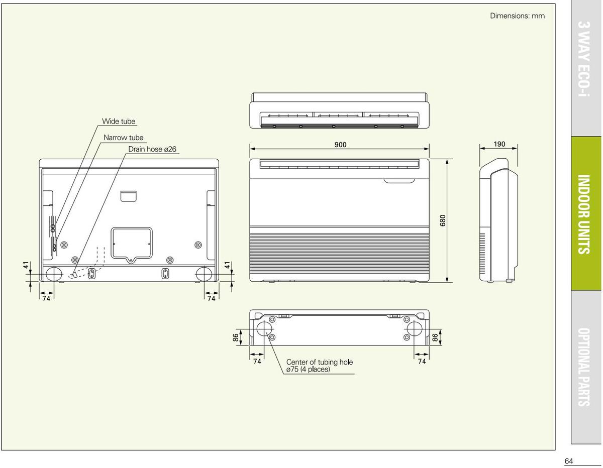
WALL-MOUNTED UNITS
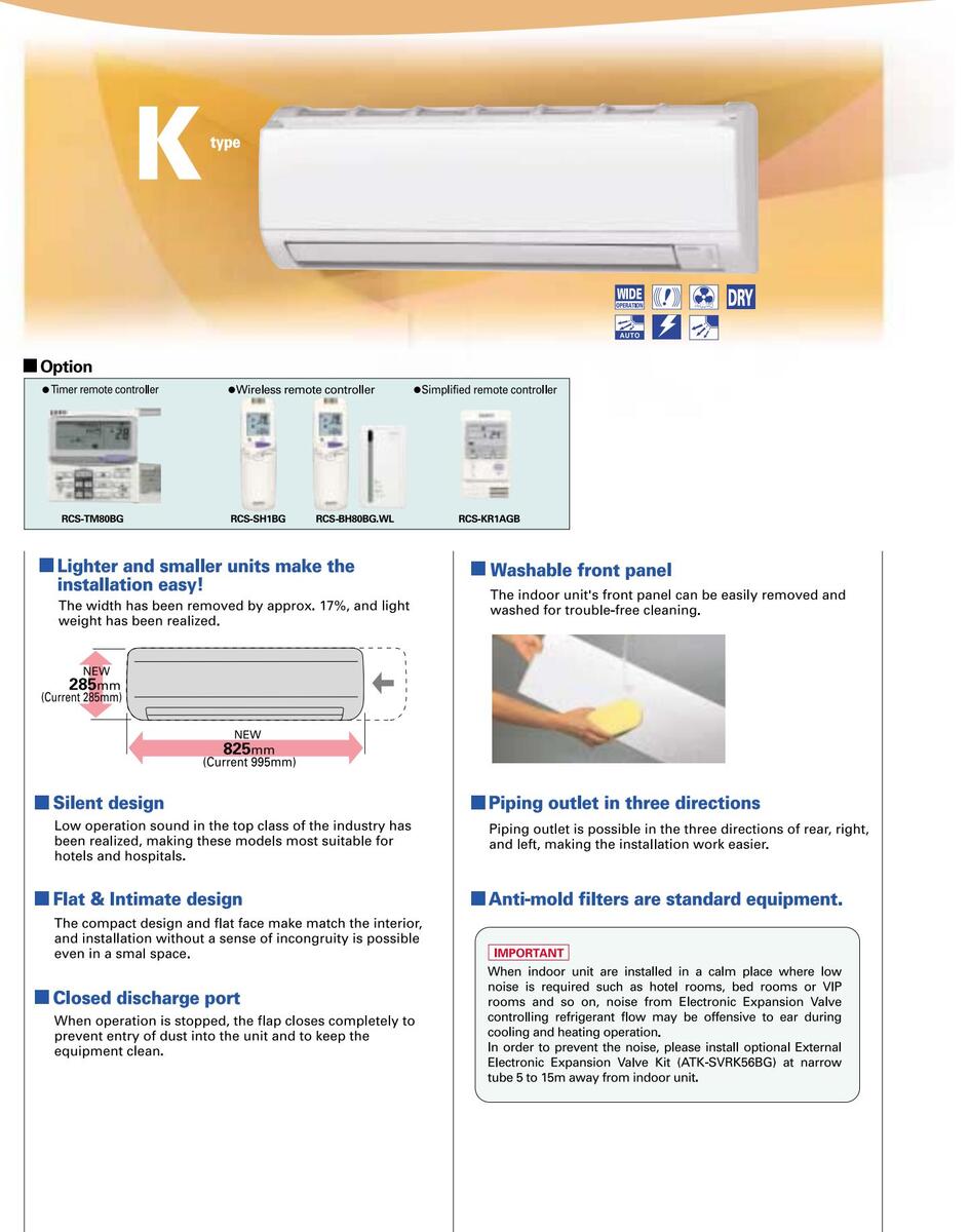
| Indoor units specifications | ||||||||
|---|---|---|---|---|---|---|---|---|
| Model nam | е | (5 | SPW-) | K075XH | K095XH | K125XH | ||
| Power source | e | 220/230/240V, 1 phase-50, 60 Hz | ||||||
| Cooling con | acity | kW | 2.2 | 2.8 | 3.6 | |||
| acity | BTU/h | 7,500 | 9,600 | 12,000 | ||||
| ooit ( | kW | 2.5 | 3.2 | 4.2 | ||||
| Heating capa | acity | BTU/h | 8,500 | 11,000 | 14,000 | |||
| Power input | Cooling | kW | 0.018/0. | 019 / 0.019 | 0.021 / 0.022 / 0.023 | |||
| 1 ower mput | Heating | kW | 0.019 / 0.0 | 019 / 0.020 | 0.022 / 0.023 / 0.023 | |||
| Running om | noroc | Cooling A | 0.16/0.16/0.16 | 0.19 / 0.19 / 0.20 | ||||
| peres | Heating | А | 0.17 / 0.17 / 0.18 | 0.20 / 0.20 / 0.20 | ||||
| Туре | ||||||||
| Fan motor | Airflow | rate (H/M/L) | m³/min | 9 / 7.5 / 6 | 10 / 8.5 / 6.5 | |||
| Outpu | t | kW | ||||||
| Power sound | l level ( | H/M/L) | dB(A) | 46 / 4 | 48 / 44 / 40 | |||
| Pressure sou | nd leve | el (H/M/L) | dB(A) | 35 / 32 / 28 37 / 33 / 29 | ||||
| ŀ | leight | mm | 285 | |||||
| Dimensions | ٧ | Vidth | mm | 825 | ||||
| ۵ | Depth | mm | 217 | |||||
| L | iquid (Flare). | mm(in) | 6.35 (1/4) | |||||
| Piping connect | ctions C | Gas (Flare) | mm(in) | 12.7 (1/2) | ||||
| Drain piping | VP-13 | |||||||
| Net weight | Net weight kg | 10 | ||||||
Rated conditions Cooling: Indoor air temperature 27°C DB/19°C WB, outdoor air temperature 35°C DB Heating: Indoor air temperature 20°C DB, outdoor air temperature 7°C DB/6°C WB
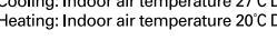
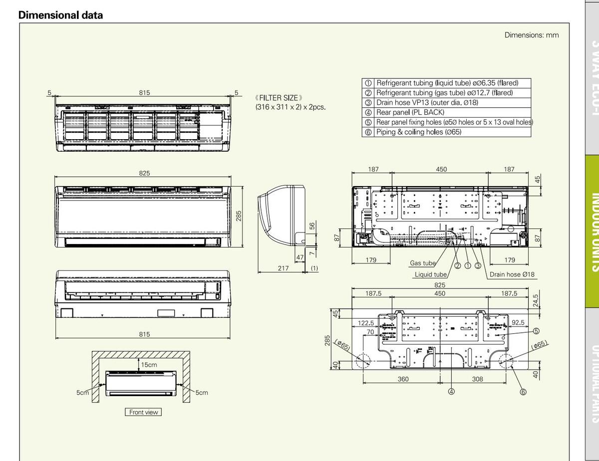
Data subject to change without notice.
Downloaded from www.Manualslib.com manuals search engine
WALL-MOUNTED UNITS
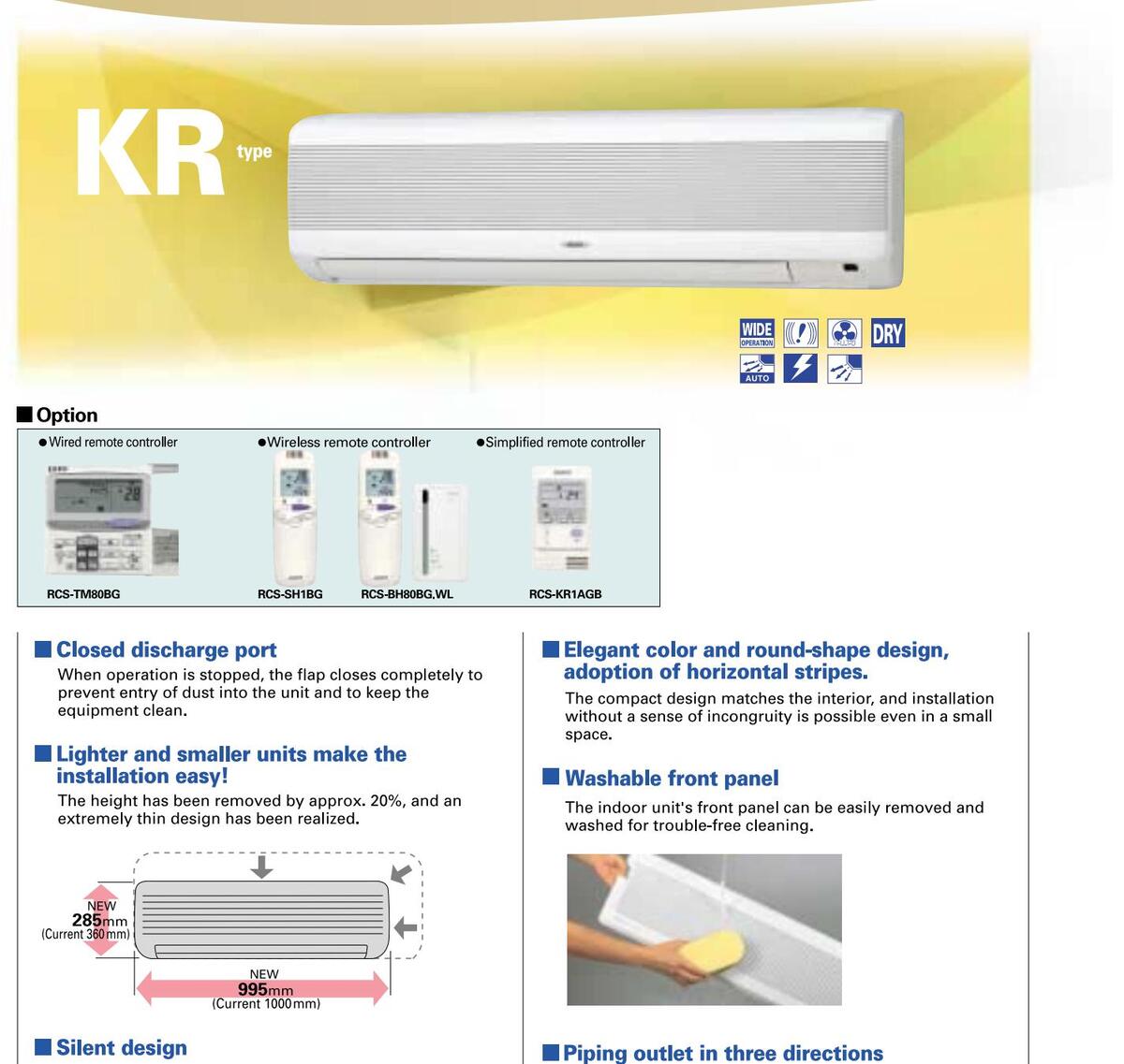
Low operation sound in the top class of the industry has been realized, making these models most suitable for hotels and hospitals.
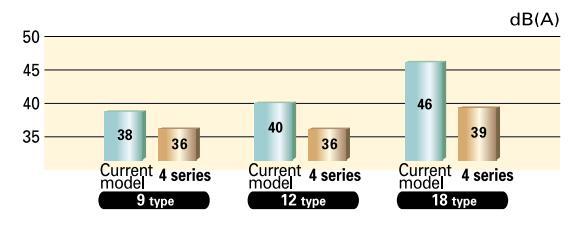
Anti-mold filters are standard equipment.
Piping outlet is possible in the three directions of rear.
right, and left, making the installation work easier.
IMPORTANT
When indoor unit are installed in a calm place where low noise is required such as hotel rooms, bed rooms or VIP rooms and so on, noise from Electronic Expansion Valve controlling refrigerant flow may be offensive to ear during cooling and heating operation.
cooling and heating operation. In order to prevent the noise, please install optional External Electronic Expansion Valve Kit (ATK-SVRK56BG, ATK-SVRK160BG (with 254 type)) at narrow tube 5 to 15m away from indoor unit.
| muoor units specification | or units specification | its specification | units | loor | Ind |
|---|
| Model nam | е | ($ | SPW-) | KR74GXH56B | KR94GXH56B | KR124GXH56B | KR164GXH56B | KR184GXH56B | KR254GXH56B | ||
|---|---|---|---|---|---|---|---|---|---|---|---|
| Power source | e | 220/230/240V, 1 | phase-50, 60 Hz | 64GXH56B KR184GXH56B KR254 >-50, 60Hz 7 4.5 5.6 7 15,000 19,000 25, 5.0 6.3 8 17,000 21,000 27, 0.049/0. 21,000 27, 0.049/0. 0.23/0 23/0 *1 12/10/8 16/1 12/10/8 16/1 0.0 *0.01 0.3 3 42/3 3 1 12/10/8 3 1 12/10/8 2 3 42/3 3 1 5 2 9 9 45 5 9 9 | |||||||
|
Model name
Power source
Cooling capacity
Heating capacity
Power input
Coo
Hea Running amperes Coo Hea Fan motor Airflow rate ( Output Power sound level (H/M/I Pressure sound level (H/M/I Dimensions Heigh Width Depth Liquid Piping connections (Gas (F Drain) Dirain |
kW | 2.2 | 2.2 2.8 3.6 4.5 5.6 | 7.3 | |||||||
| cooning capa | acity | BTU/h | 7,500 | 9,600 | 12,000 | 15,000 | 19,000 | 25,000 | |||
| Heating capacity | kW | 2.5 | 3.2 | 4.2 | 5.0 | 6.3 | 8.0 | ||||
| Treating capa | acity | BTU/h | 8,500 | 11,000 | 14,000 | KR164GXH56B KR184 1 phase-50, 60Hz 4.5 15,000 19 5.0 11 17,000 2 5 5 10w fan *1 12/10/8 0.015 0.015 | 21,000 | 27,000 | |||
| Power input | Cooling | kW | 0.031/0.033/0.035 | 0.049/0.052/0.055 | |||||||
| i ower input | Heating | kW | 0.031/0.033/0.035 | 0.049/0.052/0.055 | |||||||
| Rupping am | noroe | Cooling | А | 0.15/0.15/0.15 | 6B KR164GXH56B KR184GXH56I IV, 1 phase-50, 60Hz 4.5 5.6 15,000 19,000 5.0 6.3 17,000 21,000 035 15 5 5 15 12/10/8 0.015 0.015 | 0.23/0.23/0.24 | |||||
| nperes Heating A 0.15/0.15/0.15 | 0.23/0.23/0.24 | ||||||||||
| Туре | Туре | ||||||||||
|
Running amp
Fan motor Power sound |
Airflow | Airflow rate (H/M/L) n | 10/8/6 | 12/1 | 10/8 | 16/14/10 | |||||
| Output kW | kW | 0.011 0.015 | 0.023 | ||||||||
| Power sound | level (H | H/M/L) | dB(A) | 47/43/39 | 53/49/46 | ||||||
| Pressure sou | nd leve | I (H/M/L) | dB(A) | 36/32/28 | 42/38/35 | ||||||
| F | leight | mm | 285 | 330 | |||||||
| Dimensions | V | Vidth | mm | 995 | KR164GXH56B KR184GXH56E 1 phase-50, 60 Hz 4.5 5.6 15,000 19,000 5.0 6.3 17,000 21,000 5 5 30wr fan *1 12/10/8 0.015 | 1140 | |||||
| C | Depth | mm | 0.15/0.15/0.15 0.23/0.23/0 Cross flow fan *1 0.23/0.23/0 10/8/6 12/10/8 16/14/10 0.011 0.015 0.023 47/43/39 53/49/40 53/49/40 36/32/28 42/38/31 42/38/31 285 330 995 1140 203 228 6.35 9.52 1140 203 228 55 12.7 15.88 VP-13 | 228 | |||||||
|
Pressure sound le
Dimensions Piping connection |
L | iquid (Flare) | mm | 6.35 | 9.52 | ||||||
| Piping connect | ctions C | Gas (Flare) | mm | 12.7 | 15.88 | ||||||
| C | Drain piping | VP | -13 | ||||||||
| Net weight | kg | 14 | 21 | ||||||||
Rated conditions Cooling: Indoor air temperature 27°C DB/19°C WB, outdoor air temperature 35°C DB Heating: Indoor air temperature 20°C DB, outdoor air temperature 7°C DB/6°C WB
Data subject to change without notice.

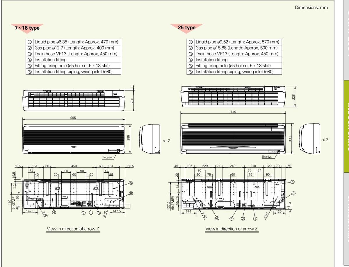
CONCEALED FLOOR STANDING UNITS
FLOOR STANDING UNITS
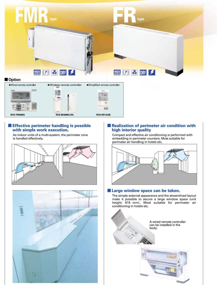
Indoor units specifications
| Model nam | e | (5 | SPW-) | FMR74GXH56B | FMR94GXH56B | FMR124GXH56B | FMR164GXH56B | FMR184GXH56B | FMR254GXH56B |
|---|---|---|---|---|---|---|---|---|---|
| Power source | e | 220/230/240V, 1 | phase 50, 60 Hz | ||||||
| Cooling | : + . | kW | 2.2 | 2.8 | 3.6 | 4.5 | 5.6 | 7.1 | |
| Cooling cap | odel name wer source oling capacity ating capacity wer input C ming amperes C Airflow ra Output wer sound level (H/I Dutput wer sound level (H/I Liquid assure sound level (H/I Liquid assure sound level (III Dra assure sound level (III Dra assure sound level (III Dra assure sound level (III Dra bing connections Gra at weight Floor Stand | BTU/h | 7,500 | 9,600 | 12,000 | 15,000 | 19,000 | 24,000 | |
| kW | 2.5 | 3.2 | 4.2 | 5.0 | 6.3 | 8.0 | |||
| пеациу сар | ng capacity | BTU/h | 8,500 | 11,000 | 14,000 | 17,000 | 21,000 | 27,000 | |
| Power input | Cooling | kW | 0.051/0.0 | )56/0.061 | 0.079/0.085/0.091 | 0.116/0.1 | 26/0.136 | 0.150/0.160/0.170 | |
| i ower niput | Heating | kW | 0.036/0.0 | )40/0.045 | 0.064/0.070/0.076 | 15,000 19,000 5.0 6.3 17,000 21,000 0.116/0.126/0.136 0.079/0.091/0.101 0.54/0.56/0.58 0.37/0.41/0.43 Sirocco fan *2 12/9/8 15/13/11 0.02 0.03 49/46/42 49/46/42 | 0.110/0.120/0.130 | ||
| Rupping am | noroc | Cooling | А | 0.24/0. | 25/0.26 | 0.37/0.38/0.39 | 0.54/0. | 17,000 21,000 0.116/0.126/0.136 0.079/0.091/0.101 0.54/0.56/0.58 0.37/0.41/0.43 Sirocco fan *2 12/9/8 15/13/11 0.02 0.03 49/46/42 49/46/42 | 0.70/0.72/0.73 |
| Nurning an | iperes | Heating | А | 0.17/0. | 18/0.19 | 0.30/0.31/0.32 | 0.37/0. | 41/0.43 | 0.52/0.54/0.56 |
| Туре | Гуре | Sirocco fan *1 | - | Sirocco fan *2 | |||||
| Fan motor | Airflow | / rate (H/M/L) | m³/min | 7/6 | 6/5 | 9/7/6 | 12/9/8 | 15/13/11 | 17/14/12 |
| Output | kW | 0. | 01 | 0.02 | 0.02 | 0.03 | 0.06 | ||
| Power sound | level ( | H/M/L) | dB(A) | 44/4 | 1/39 | 50/46/40 | 49/46/42 | 49/46/42 | 52/49/46 |
| Pressure sou | ind leve | el (H/M/L) | dB(A) | 33/30/28 | 39/35/29 | 38/35/31 | 39/36/31 | 41/38/35 | |
| Dimensions | ŀ | HxWxD | mm | 616×904×229 | 616x1219x229 | ||||
| L | _iquid (Flare) | mm | 6.35 9.52 | ||||||
| Piping conne | ctions | Gas (Flare) | mm | 12.7 | 15.88 | ||||
| Drain piping | VP | -20 | |||||||
| Net weight | kg | 21 | 28 | ||||||
| Floor Standing type | |||||||||
FR164GXH56B
FR94GXH56B
d conc oling: I
`00l
3, outdoor air temperature 35°C D r air temperature 7°C DB/6°C WB
Coolir
FR74GXH56B
Di nal data
Airflo
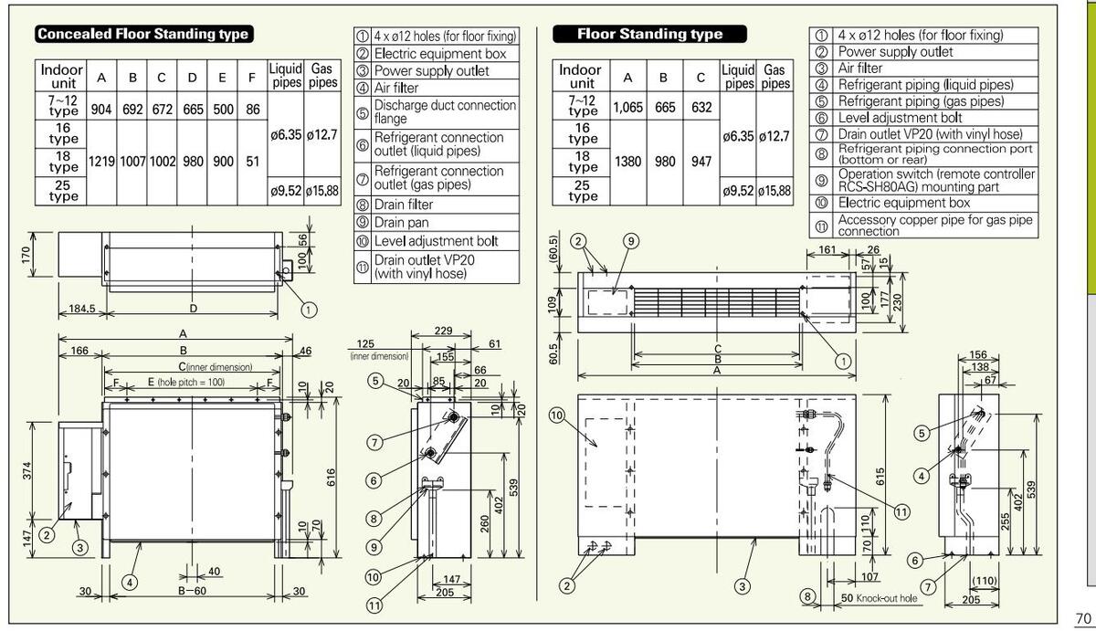
Downloaded from www.Manualslib.com manuals search engine
FR184GXH56B FR254GXH56E
TOTAL HEAT EXCHANGER WITH DX COIL
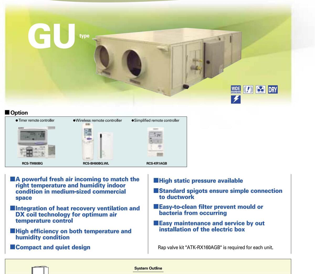
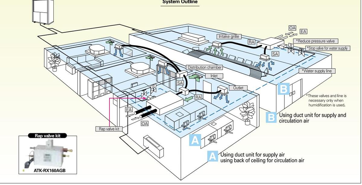
Indoor units specifications
| Mode | el name | (S | SPW-) | GU055XH | GU075XH | GU105XH |
|---|---|---|---|---|---|---|
| Air cir | culation (H) | m³/h | 500 | 750 | 1,000 | |
| Powe | r source | 220/230/240V, 1 phase-50Hz | ||||
| Fresh | Air Load | Cooling | kW | 5.3 (1.7)* 1 | 8.2 (2.6)*1 | 10.7 (3.4)* 1 |
| Treatm | nent Capacity | Heating | kW | 6.5 (2.3)* 1 | 9.8 (3.5)* 1 | 12.6 (4.6)* 1 |
| Enthal | py Exchange | Cooling | % | 59 | ||
| Efficier | ncy | Heating | % | 750 220/230/240V, 1 phase-50Hz 8.2 (2.6)*1 9.8 (3.5)*1 59 67 75 5.6 19,000 0.737/0.737 0.737/0.737 3.4/3.2/3.1 Sirocco fan 221 (188) 264 (218) 0.35 (4P)×2 58 (Cooling), 59 (Heating) 47 (Cooling), 48 (Heating) 1120 6.35 (1/4) 12.7 (1/2) VP-25 153 | ||
| Temp. | Exchange Effi | ciency | % | 75 | ||
| Equiva | lent cooling o | anacity | kW | 3.6 | 5.6 | 7.3 |
| Lquiva | арасну | BTU/h | 12,000 | 8.2 (2.6)*1 9.8 (3.5)*1 59 67 75 5.6 19,000 0.737/0.737 3.4/3.2/3.1 Sirocco fan 221 (188) 264 (218) 0.35 ( 58 (Cooling), 59 (Heating) 47 (Cooling), 48 (Heating) 47 19 1120 | 25,000 | |
| Power | input | Cooling | kW | 0.532/0.532/0.532 | 0.737/0.737/0.737 | 0.798/0.798/0.798 |
| TOWER | mput | Heating | kW | 0.532/0.532/0.532 | 0.737/0.737/0.737 | 0.798/0.798/0.798 |
| Ruppi | na amporoc | Cooling | А | 2.5/2.4/2.3 | 3.4/3.2/3.1 | 3.7/3.5/3.4 |
| numm | ng amperes | Heating | А | 2.5/2.4/2.3 | 3.4/3.2/3.1 | 3.7/3.5/3.4 |
| Туре | Sirocco fan | |||||
| Fan | External static | pressure-Returi | nair Pa | 183 (170) | 221 (188) | 135 (88) |
| motor | External static | pressure-Supp | yair Pa | 205 (182) | 264 (218) | 176 (137) |
| Output | kW | 0.28 (4P)×2 | 0.35 ( | 4P)×2 | ||
| Power | r sound level | (C/H) | dB(A) | 57 (Cooling), 58 (Heating) | 58 (Cooling), 59 (Heating) | 59 (Cooling), 60 (Heating) |
| Pressu | ure sound lev | el (C/H) | dB(A) | 46 (Cooling), 47 (Heating) | 47 (Cooling), 48 (Heating) | 48 (Cooling), 49 (Heating) |
| Height | mm | 425 | 4 | 50 | ||
| Power sound level ( Pressure sound leve Dimensions I | Width | mm | 1785 | 19 | 03 | |
| Depth | mm | 1000 | 1120 | 1220 | ||
| Liquid (Flare) | mm | 6.35 (1/4) | ||||
| Piping | connections | Gas (Flare) | mm | 12.7 (1/2) | ||
| Drain piping | VP-25 | |||||
| Conne | ction Duct Dia | imeter | mm | 25 | 50 | 300 |
| Net w | reight | kg | 134 | 153 | 168 | |
| Rated co | onditions | * The values in ( ) for the external static pressur | e and operating sound are for use of booster cable. |
Cooling: Indoor air temperature 27'C DB/19'C WB, outdoor air temperature 35'C DB Heating: Indoor air temperature 20'C DB, outdoor air temperature 7'C DB/6'C WB
xternal static pressure and operating sound are for use of booster cable. *1: Heat recovery capacity by heat exchanger. Data subject to change without notice.
Dimensional data
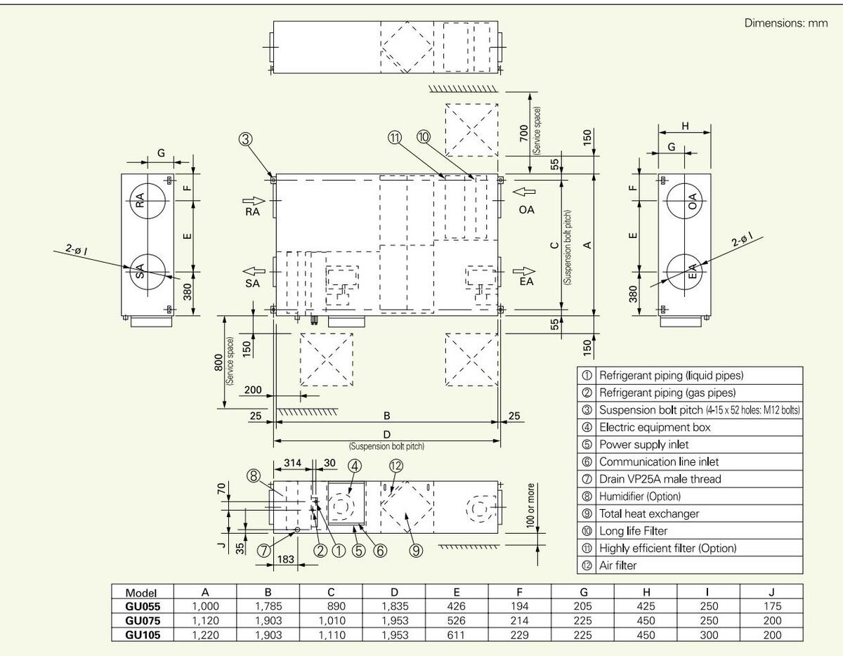
Sanyo control equipment meets the needs of various of customers.
| Operation system | Operation system Individual control systems | ||||||
|---|---|---|---|---|---|---|---|
| Needs | Normal operation |
Operation from
each seat |
Quick and
easy operation |
Daily and
weekly program |
|||
| External appearance | |||||||
| Type, model name |
Wired remote
controller RCS-TM80BG |
Wireless remote
controller RCS-XM18BG.WL RCS-SH80BG.WL RCS-SS80BG.WL RCS-BH80BG.WL RCS-TRP80BG.WL RCS-SH1BG |
Simplified remote
controller RCS-KR1AGB |
Schedule timer
SHA-TM64AGB |
|||
|
Number of indoor
units which can be controlled |
1 group, 8 units | 1 group, 8 units | 1 group, 8 units |
64 groups,
max. 64 units |
|||
| Use limitations | ●Up to 2 units can be connected per group. | ●Up to 2 units can be connected per group. | ●Up to 2 units can be connected per group. |
|
|||
|
Connectable
indoor unit |
4 & 5 series indoor unit | 4 & 5 series indoor unit | 4 & 5 series indoor unit | 4 & 5 series indoor unit | |||
| ON/OFF | 0 | 0 | 0 | ||||
| Mode setting | 0 | 0 | 0 | ||||
| Fan speed setting | 0 | 0 | 0 | — | |||
| Temperature setting | 0 | 0 | 0 | ||||
| Air flow direction | 0 | 0 | 0 | ||||
|
Permit/Prohibit
switching |
_ | _ | |||||
| Weekly program | 0 | — | 0 | ||||
*1 Select two of the following: "Fan speed", "Air flow direction", "Central/Individual", and "Filter sign". *2 Setting is not possible when a remote control unit is present. (Use the remote control for setting.)

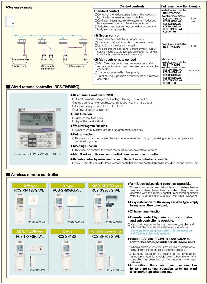
Remote controller (Wired remote controller/Wireless remote controller)
_____75
Simplified remote controller (RCS-KR1AGB)
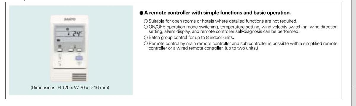
Schedule timer (SHA-TM64AGB)
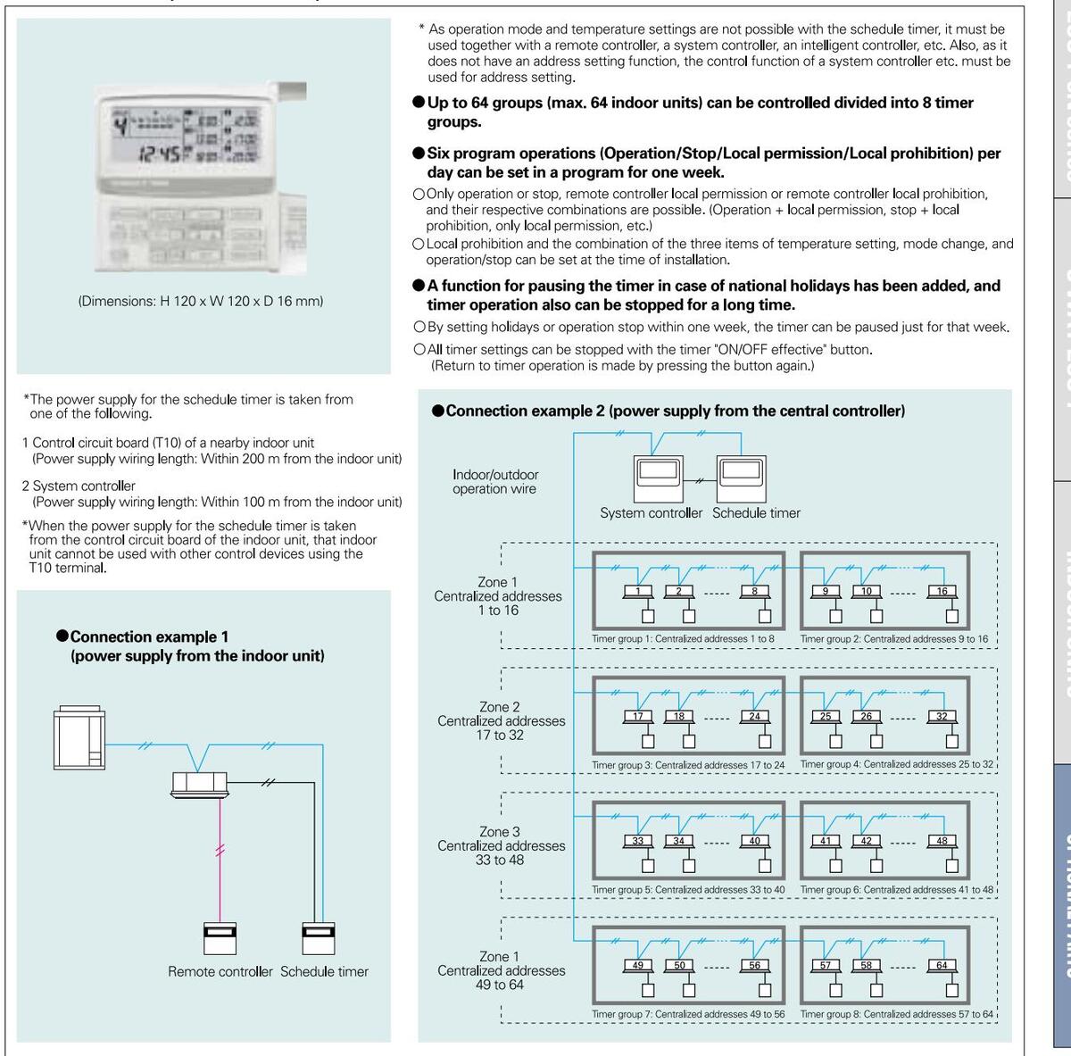
Downloaded from www.Manualslib.com manuals search engine
System controller (SHA-KC64AGB)
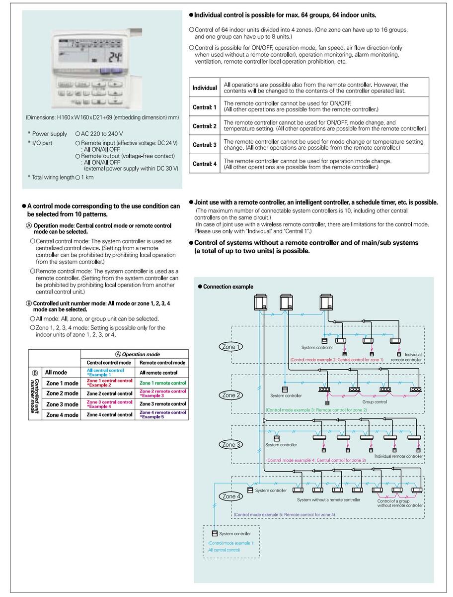
_____77
Intelligent controller (SHA-KT256EG)
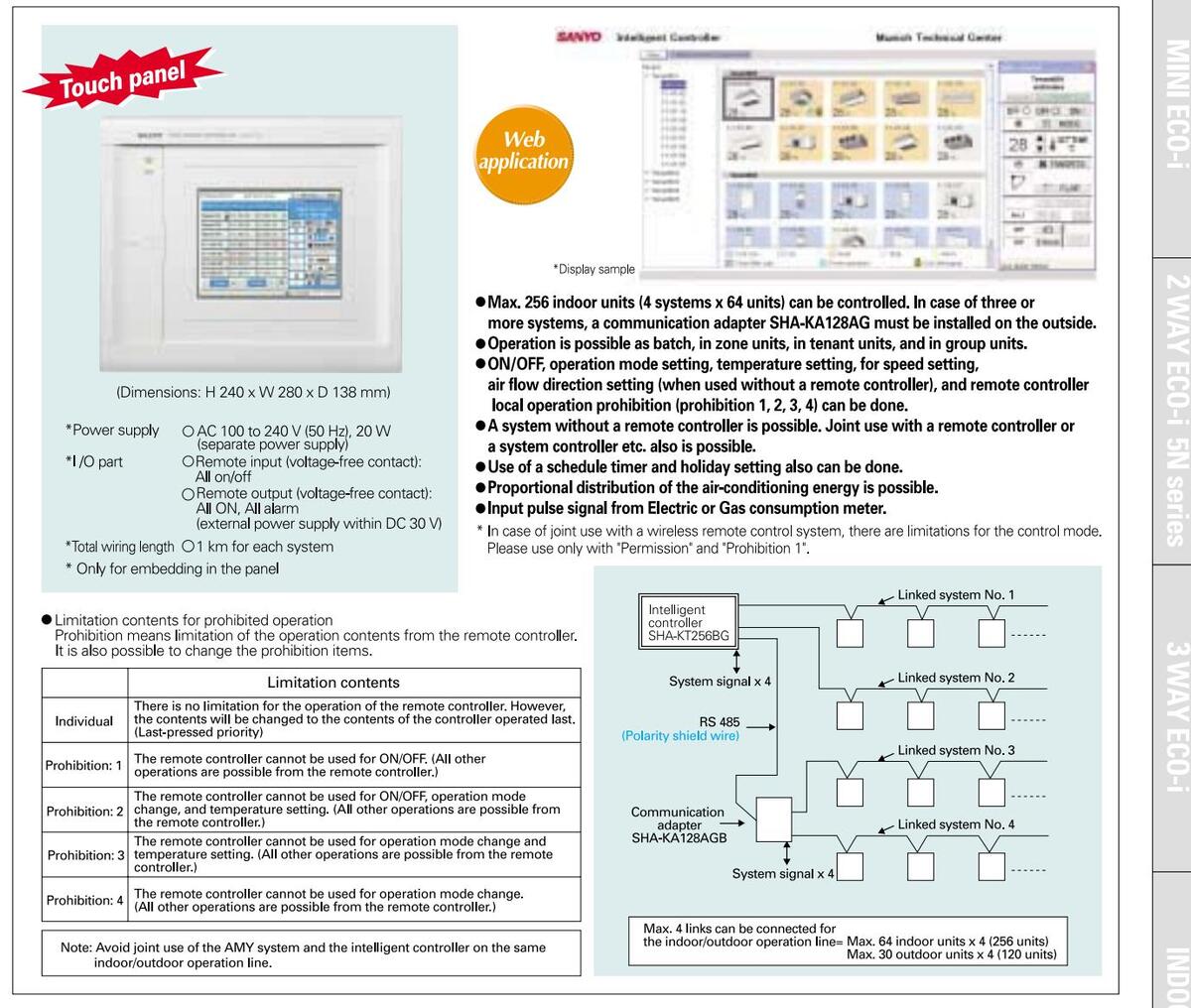
Communication adaptor (SHA-KA128AGB)
| Internet of | |
|---|---|
| - | |
|
(Dimensions
* Power sup |
s: H 260 x W 200 x D 68 mm)
ply: AC 100 to 240 V (50 Hz), |
- Required to connect three or more linked wiring systems (indoor/outdoor operation lines) to the intelligent controller.
- Also required for connection of the AMY software. * For more detail, please take a look at page 58.
-
Two linked wiring systems can be connected to one SHA-KA128AG, but max. 4 systems can be connected for the entire intelligent controllers.
- * As this is not a splash-proof design, it must be installed indoors or in the control panel etc.
ON/OFF controller (SHA-KC16KAGB)

Remote sensor (ART-K45AGB)
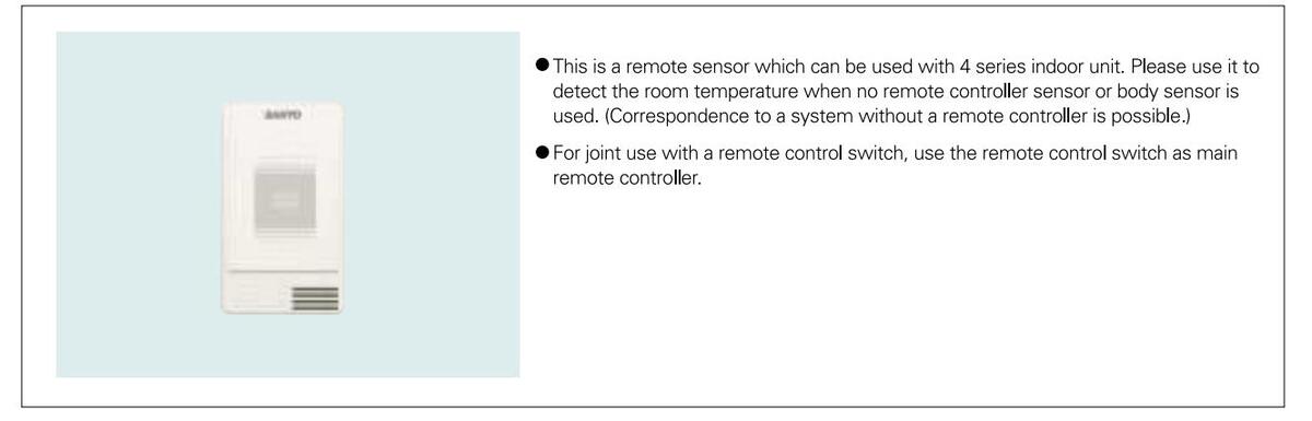
Signal output board (ACC-SG-AGB)
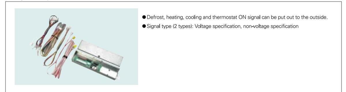
_____79
Seri-Para I/O Unit for indoor unit (ACC-SP16TAG)
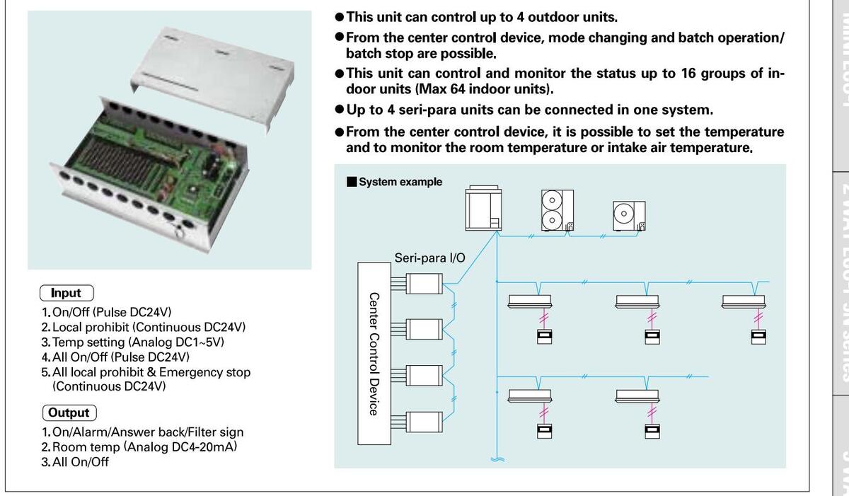
LonWorks Interface (SHA-LN16UGB)
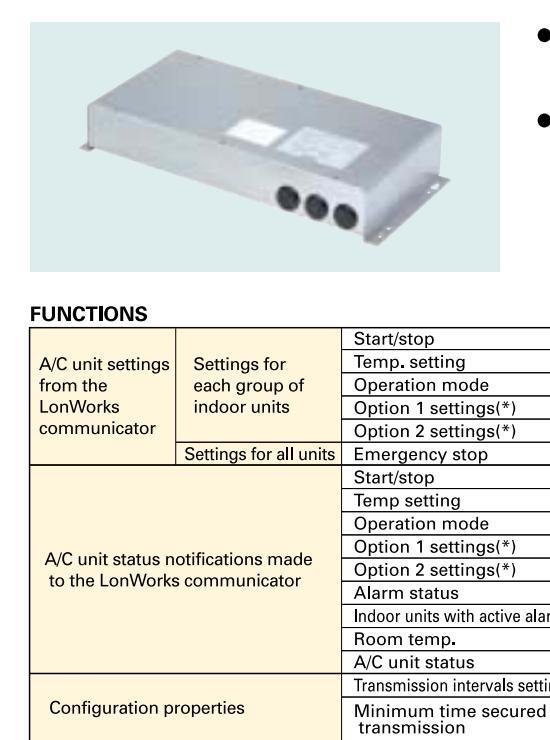
Select two of the following: remote controller prohibit, fan speed setting air direction setting, filter sign reset.
Downloaded from www.Manualslib.com manuals search engine

• From the host connected to LonWorks, basic settings and status monitoring is possible for up to 16 groups of A/C units.

MINI ECO-i
INDOOR UNITS
80
Convenient system control
Seri-Para I/O unit for outdoor unit (ACC-XSP4U1GB)
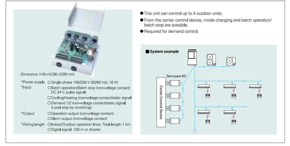
MINI Seri-Para I/O Unit (ACC-SP1AGB)
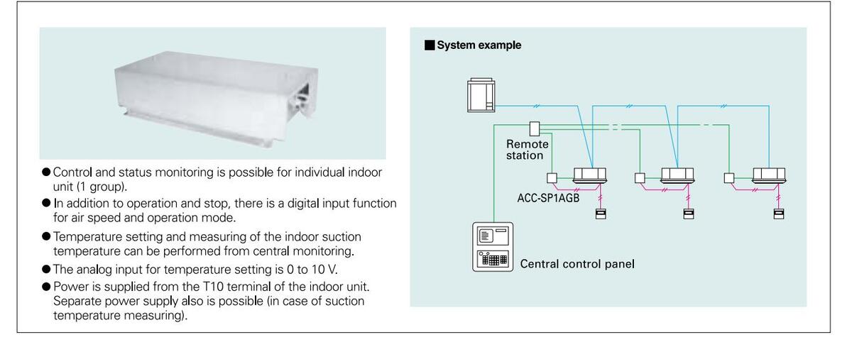
■Local adaptor for ON/OFF control (SHA-KL4UGB)
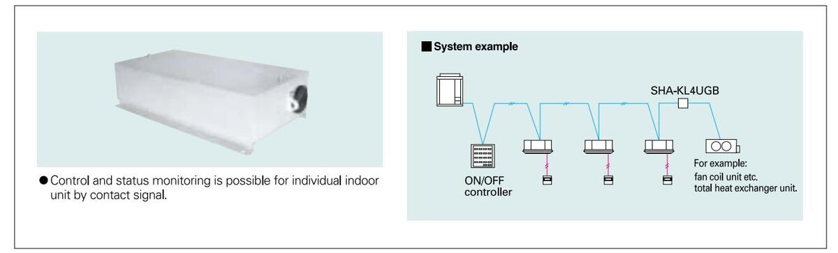
_____81
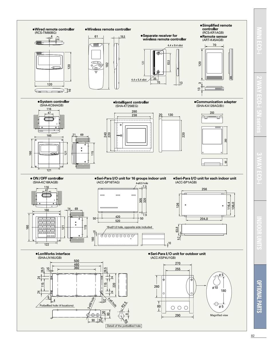
Sanyo Total Air Intelligent Management System

In regard to CFC regulations and substitute refrigerant (HFC-type refrigerant R407C, R410A)
Since depletion of the ozone layer from CFC refrigerant (R11, R12, etc.) has become a global issue, an Ozone Layer Protection Law was enacted in 1988. Accordingly, CFC refrigerant production was globally terminated in 1995. Since HCFC22 refrigerant contains chlorine, its production is also regulated and will be terminated by 2020. The HFC-type refrigerants R407C and R410A both cause no harm to the ozone layer, and it is expected that they will be safe substitute refrigerants.
New refrigerants
The new refrigerant R407 is a non-azeotropic refrigerant mixture of three types (R32, R125, and R134a), and R410A is a pseudo-azeotropic refrigerant mixture of two types (R32, R125). Both do not contain chlorine (ozone layer depletion potential = 0).
| Refrigerant | Ingredients |
Refrigerant ratio
(wt%) |
Ozone layer
depletion potential |
Combustibility | |||
|---|---|---|---|---|---|---|---|
| R407C HFC32/HFC125/HFC134a | 0 | None | |||||
| R410A | HFC32/HFC125 | 50/50 | Ū | None | |||
| Conventional refrigerant | HCFC (Hydro Chloro Fluoro Carbon) | R22 | HCFC22 | 100 | 0.05 | None | |
Precaution for the installation work
|
R407C, R410A applies higher pressure than R22 and
uses refrigeration oil different from R22. Therefore, piping works and tools are also different from those for |
Refrigerant |
Conventional refrigerant
R22 |
New ref |
rigerant
R410A |
|---|---|---|---|---|
| R22 refrigerants. | (single refrigerant) | (refrigerant mixture) | (refrigerant mixture) | |
| Refrigeration oil | Mineral oil (Suniso) | Synthetic (ether) oil | Synthetic (ether) oil | |
| Condensing pressure | 1.9MPa(100%) | 2.1MPa(110%) | 3.1MPa(160%) |
Additional Refrigerant Charge
Additional refrigerant charge amount is calculated from the narrow tubing total length as follows.
Tools specifically
• Please note that tools for new refrigerants R407C and R410A are different from those for R22.
Compatibility of representative tools for the installation
| Na | E muin mante na ma | Annliestion | Compatibility | ||
|---|---|---|---|---|---|
| INO | Equipment name | Application | R407C | R410A | |
| 1 | Gauge manifold charging hose | Vacuum drying, refrigerant additional charging | Only for R407C | Only for R410A | |
| 2 | Vacuum pump |
Vacuum drying
(Use is possible when a reverse-flow prevention adapter is attached.) |
Joint use with R22 | Joint use with R22 | |
| 3 | Reverse-flow prevention vacuum pump adapter | Must be used for vacuum drying. | Joint use with R22 |
Joint use with R22
(Use the accessory adapter.) |
|
| 4 |
Weighting scale for
refrigerant charging |
Measuring the refrigerant charging | Joint use with R22 | Joint use with R22 | |
| 5 | Torque wrench | For tightening of flare nuts | Joint use with R22 | Only for R410A (1/2, 5/8) | |
| 6 | Flaring tool (clutch type) | Piping flare processing |
Joint use with R22
(A specialized version also exists.) |
Joint use with R22
(A specialized version also exists.) |
|
| 7 | Adjustment tool for piping flare | Used when a conventional flaring tool is used for flare processing | Joint use with R22 | Only for R410A | |
| 8 | Charge port for refrigerant cylinder | For prevention of erroneous use | Only for R407C | Only for R410A | |
| 9 | Refrigerant cylinder |
Refrigerant filling.
(Refrigerant color application at the upper part of the cylinder) |
Only for R407C (brown) | Only for R410A (pink) | |
| 10 | Gas leakage detector | Gas leakage check (As the HFC-type refrigerants R407C and R410A do not contain chlorine, a detector for R22 cannot be used.) |
Only for HFC-type refrigerant
(joint use for R407C and R410A) |
Only for HFC-type refrigerant
(joint use for R407C and R410A) |
|
| 11 | Pipe cutter, pipe bender | Pipe cutting, pipe bending | Joint use with R22 | Joint use with R22 | |
| 12 | Welder, nitrogen cylinder | Pipe welding | Joint use with R22 | Joint use with R22 | |
MINI ECO-i
Optional parts/Distribution joint kit for 2 WAY ECO-i 5N series
Distribution joint kit
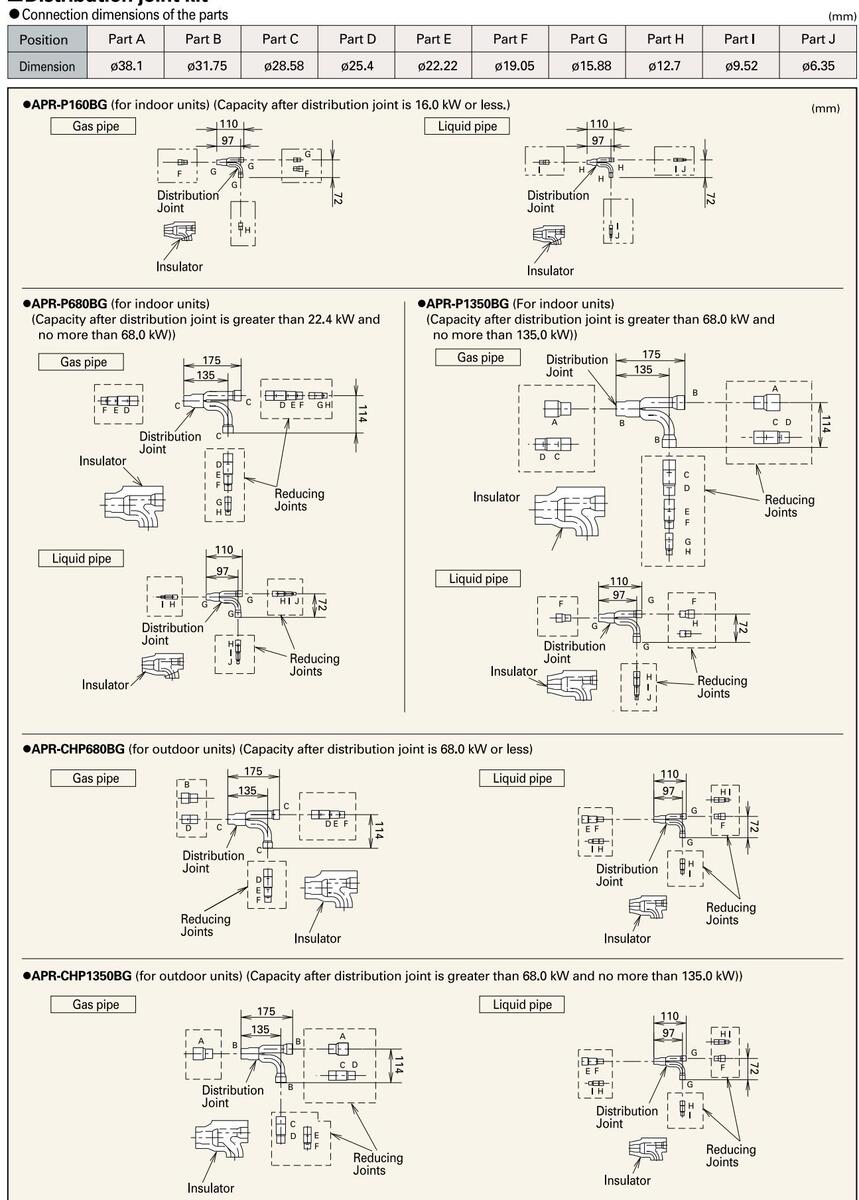
_____85
Optional parts/Distribution joint kit for 3 WAY ECO-I MULTI
Distribution joint kit on Part A Part B Part C Part F Part F Part I Part D Part G Part H Part J ø38.1 ø31.75 ø28.58 ø25.4 ø22.22 ø19.05 ø15.88 ø6.35 •APR-RZP224BGB (for indoor units) (Capacity after distribution ioint is 22.4 kW or less.) Liquid pipe iquid pipe •APR-RZP1350BGB (for indoor units) (Capacity after distribution joint is greater than 68.0 kW and no more than 135.0 kW)) Suction pipe Liquid pipe 105 •APR-CHRZP680BGB (for outdoor units) (Capacity after distribution joint is 68.0 kW or less.) •APR-CHRZP1350BGB (for outdoor units) (Capacity after distribution joint is greater than 68.0 kW and no more than 135.0 kW)) Suction pipe Inculato
SANYO reserves the right to make any variation in specifi cation to the equipment described or to withdraw or replace products without prior notification or public announcement. All descriptions, illustrations, drawings and specifi cations in this publication are given in good faith, but are intended to present only general particulars and shall not form any part of the contract. For full installation details, please contact your SANYO distributor.
REF: ECOSG08V1
Rating Conditions The cooling and heating capacities are based on the following conditions Cooling: Indoor temperature 27°C DB / 19°C WB, Outdoor temperature 35°C DB / 24° C WB. Heating: Indoor temperature 20°C DB, Outdoor Temperature 7°C DB 6°C WB.

Printed using paper produced from 50% recycled material and 50% from sustainable forestry.

SANYO Air Conditioners. The natural choice.

SANYO Electric Co., Ltd. SANYO Airconditioners Europe S.r.I. ©2008. 5 SANYO


 Loading...