

Page 1
Service Manual
Biomedical Freezer
MDF-U5412
FILE No.
SANYO Electric Co., Ltd.
Biomedical Business Division
SM9910214
Page 2

Effective models
This service manual is effective following models.
Model Product code Voltage and Frequency
MDF-U5412 823 018 53 220V 60Hz
823 018 54 230/240V 50Hz
823 018 56 220V 50Hz
Page 3

Contents
Page
Features ------------------------------------------- 1
Specifications ------------------------------------------- 2
- Structural specifications
- Control specifications
- Performance specifications
Dimensions ------------------------------------------- 4
Cooling unit parts ------------------------------------------- 5
Refrigeration circuit ------------------------------------------- 6
Electric components ------------------------------------------- 7
Components on PCB ------------------------------------------- 8
Specifications of sensor ------------------------------------------- 9
Control specifications ------------------------------------------- 10
Wiring diagram ------------------------------------------- 17
Circuit diagram ------------------------------------------- 18
Parts layout ------------------------------------------- 19
Test data ------------------------------------------- 22
- Pull-down characteristics
- Pull-up characteristics
- Pull-down pressure
- Pull-down power consumption & current
- Temperature uniformity
- Amount of power consumption
- Temperatures during cycle
Instruction manual ------------------------------------------- 27
Page 4

Features
䂓㩷 Temperature control
New cooling system realizes to set to -20㷄 which is suitable for reagent preservation
with ambient temperature at 30㷄.
䂓㩷 HFC refrigerant
Refrigerant circuit contains HFC refrigerant that effects to environment little.
Latest cooling system reduces negative factor to global environment. With ambient
temperature at 30㷄, while temperature of inside chamber maintains -40㷄.
䂓㩷 Specification unified
Unified specification for same categories, which also realized to unify performance for
high/low temperature alarm (the available setting range is between +5㷄 and +15㷄 for
high temperature alarm, -5㷄 and -15㷄 for low temperature alarm against the set
temperature), power failure alarm, remote alarm terminal, setting memorization by
non-volatile memory.
䂓㩷 Self diagnosis function
Abnormal condition for temperature sensor is indicated as E1/E2 by self-diagnosis
system.
䂓㩷 Storage box
Storage box makes easily to access and arrange for stores.
䂓㩷 Validation
Control panel enable Zero “0” adjust for validation.
䂓㩷 Door latch mechanism
Door latch prevents the door from being ajar to preserve reagent without damaged.
Individual lock can be arranged. (Consult to your sales representative)
- 1 -
Page 5
Specifications
Structural specifications
Item Specification
Name Biomedical freezer
Model MDF-U5412
Exterior dimensions
Interior dimensions
Effective capacity 482 liters
Exterior Painted steel
Interior cabinet Styrol resin
Outer door 2, Painted steel
Door latch 2
Door lock 1
Insulation Rigid polyurethane foamed-in place
Access port
Caster 4
Leveling legs 2
Weight 134 Kg
W 804 㬍 D 772 㬍 H 1802 mm
W 658 㬍 D 607 㬍 H 1272 mm
㱢30mm, 2 on back side
Evaporator Tube on sheet type (also used as a shelf)
Condenser Wire and tube type
Compressor Hermetic rotary type, 400W
Compressor oil Ze-NIUSL22SA
Refrigerant R-404A (HFC refrigerant)
Battery
Accessories
Power supply Single phase, local voltage
Optional components
For power failure alarm, Nickel hydrogen battery, DC6V
1100mAh, Automatic charge (5HR-AAC)
1 set of key, 1 scraper
6 small baskets for upper chamber (W290 x D536 x H136 mm)
4 large baskets for lower chamber (W290 x D536 x H238 mm)
Temperature recorder: MTR-4015LH, MTR-G85
Mounting kit for MTR-4015LH: MPR-S30
Mounting kit for MTR-G85: MPR-S7
Interface board: MTR-480, MTR-L03
- 2 -
Page 6
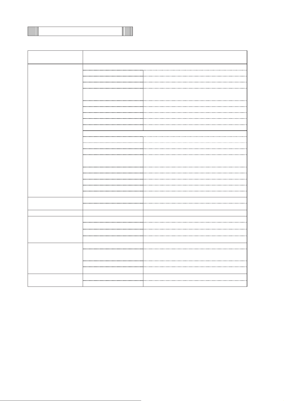
Control specifications
Item Specification
Microprocessor controlled system with non-volatilized memory.
Temperature controller
Temperature sensor Thermistor sensor (Type: 502AT)
Temperature display
High temp.
Low temp.
Remote alarm
Alarms
Control panel
Key lock function
Self diagnosis function
Compressor protection Overload relay (Internal)
Alarm resume
time
Battery age
Fan motor age
Power failure
Settable range : -18㷄䌾-45㷄 (unit:1㷄)
Memorized by Non-volatile memory
LED digital display (Unit: 1㷄)
Range : -50㷄䌾+50㷄
SV+5㷄䌾+15㷄, changeable (Initial:+10㷄)
ALARM lamp and LED display brink, buzzer beeps and remote alarm
activates with 15min. of delay
SV-5㷄䌾-15㷄, changeable (Initial:-10㷄)
ALARM lamp and LED display brink, buzzer beeps and remote alarm
activates with 15min. of delay
Remote alarm terminal 3P; contact capacity DC30V, 2A (Max)
Remote alarm activates when temp. alarm or power failure occur.
Buzzer beeps again after alarm resume time expires
Range; 10~60 min, changeable (Initial: 30min.) (Unit: 10min.)
000: Not resumed
When battery accumulation time reaches about 2.8 years, battery will
be recommended to replace by displaying chamber temperature and
‘F1’ alternately.
When fan motor accumulation time reaches about 5.6 years, fan motor
will be recommended to replace by displaying chamber temperature
and ‘F1’ alternately.
ALARM lamp brinks, buzzer beeps and LED display turns off.
Remote alarm activates.
ALARM lamp
BUZZER: Buzzer stop key
ALARM TEST: Alarm test key
SET: Setting key
䋾: Digit shift key
㺢: Numerical value shift key
DEF: Defrost key
Press 䋾key for 5 seconds to step in Key Lock mode.
L0: Unlocked L1: Locked
When a sensor is failed, error code and chamber temperature are
displayed alternately.
Remote alarm activates and buzzer beeps.
Performance specifications
Item Specification
Cooling performance
Temperature control range
Power source 220V, 50Hz 220V, 60Hz 230/240V, 50Hz
Rated power consumption 240W 285W 255/290W
Noise level
Maximum pressure 1.80MPa
-40㷄 (AT;30㷄, no load)
-20㷄䌾-40㷄
42dB [䌁] (background noise; 20 dB)
- 3 -
Page 7
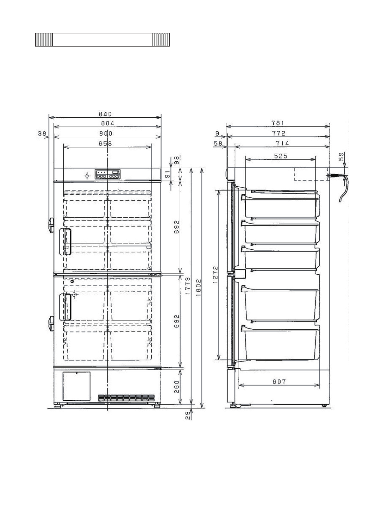
Dimensions
- 4 -
Page 8
Cooling unit parts
MDF-U5412
Parts name Specifications
Compressor
Dryer Type D-SM032T
Capillary tube
Condenser
Refrigerant
<For 220~240V, 50Hz>
Type C-1RN40L5C
Compressor cord 802 012 152
Rated power supply Single phase, 220~240V, 50Hz
Oil
Cooling method Air circulation by fan
Starting relay AMVL-300A
Overload relay Internal
Starting capacitor 40μF-300VAC
Running capacitor 12μF-370VAC
<For 220V, 60Hz>
Type C-1RN40L6A
Compressor cord 802 012 162
Rated power supply Single phase, 220V, 60Hz
Oil
Cooling method Air circulation by fan
PTC AMVL-300A
Overload relay Internal
Starting capacitor 40μF-300VAC
Running capacitor 10μF-400VAC
Type Direct cooling tube on sheet type Evaporator
Accumulator
Resistance 0.73MPaG
Length䋨L䋩
Outer diameter䋨OD䋩㱢1.8 mm
Inner diameter䋨ID䋩㱢0.7 mm
Type Natural convection
Condenser
Pre-condenser ----Frame pipe
Type
Oil additive n-pentane Charged q’ty: 11g (18cc)
Ze-NIUSL22SA
Charged q㵭ty: 230cc
Ze-NIUSL22SA
Charged q㵭ty: 230cc
㱢30 × L140 × T1.0 mm
4500 mm
Wire and tube type
1 line × 6 columns x P40mm × W480 mm
㱢4.0 x T0.5
R-404A Charged q㵭ty: 259g
- 5 -
Page 9
≧≧≧
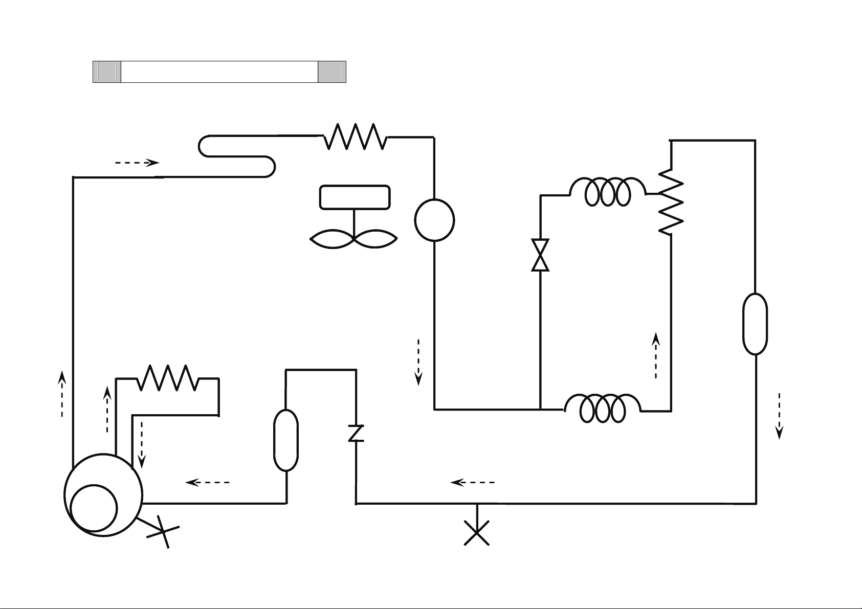
Refrigeration Circuit
- 6 -
Pre-condenser
Frame pipe
Condenser
Accumulator
Check valve
Dryer
Capillary tube
Solenoid valve
Capillary tube
Evaporator
Header
Compressor
X
• • • • •
Point to evacuate
Page 10
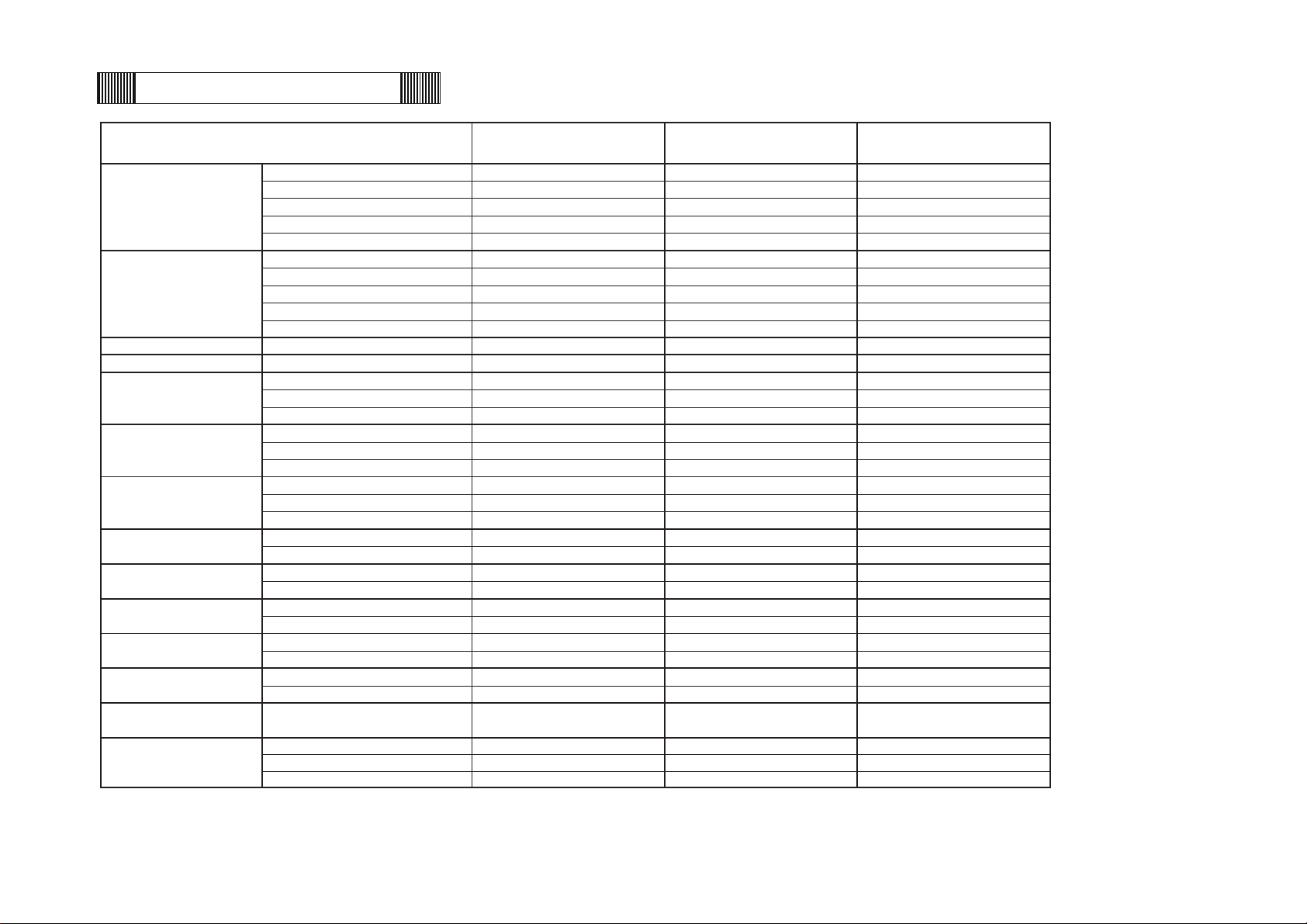
Compresso
r
Type C-1RN40L6
A
C-1RN4L5C C-1RN4L5C
Code 802 012 16 802 012 15 802 012 15
Rated voltage (50/60Hz) 220V, 60Hz 220~240V, 50Hz 220~240V, 50Hz
Winding resistance C-R(Main) 5.34㱅(25㷄)7.37㱅(25㷄)7.37㱅(25㷄)
C-S(Aux) 8.88㱅(25㷄) 15.76㱅(25㷄) 15.76㱅(25㷄)
Startin
g
rela
y
Type AMVL-300
A
AMVL-300
A
AMVL-300
A
Pick up voltage AC185V~217V AC185V~217V AC185V~217V
AC215V~232V AC215V~232V AC215V~232V
Drop out voltage AC60~120V AC60~120V AC60~120V
AC69~132V AC69~132V AC69~132V
Starting capacito
r
Rating 40㱘F, 300VAC 40㱘F, 300VAC 40㱘F, 300VAC
Running capacito
r
Rating 10㱘F, 400VAC 12㱘F, 370VAC 12㱘F, 370VAC
Temp. control rela
y
Type G4F-11123T G4F-11123T G4F-11123T
Contact capacit
y
AC220V, 20
A
AC220V, 20
A
AC220V, 20
A
Coil DC12V DC12V DC12V
Solenoid valve rela
y
Type G2R-1A-T G2R-1A-T G2R-1A-T
Contact capacit
y
AC250V, 10
A
AC250V, 10
A
AC250V, 10
A
Coil DC12V DC12V DC12V
Switching power suppl
y
Type ZWS10-12/J ZWS10-12/J ZWS10-12/J
Input AC100-240V 50-60Hz, 0.3
A
AC100-240V 50-60Hz, 0.3AAC100-240V 50-60Hz, 0.3
A
Rated outpu
t
DC12V, 0.85
A
DC12V, 0.85
A
DC12V, 0.85
A
Temp. senso
r
Type 502AT-1 502AT-1 502AT-1
Rating 5K㱅, 25㷄 5K㱅, 25㷄 5K㱅, 25㷄
Valve senso
r
Type 502AT-1 502AT-1 502AT-1
Rating 5K㱅, 25㷄 5K㱅, 25㷄 5K㱅, 25㷄
Batter
y
Type 5HR-AAC 5HR-AAC 5HR-AAC
Rating 6V 1100MAH 6V 1100MAH 6V 1100MAH
Batter
y
switch
Type SLE6A2-5 SLE6A2-5 SLE6A2-5
Rating AC250V 4
A
AC250V 4
A
AC250V 4
A
Breaker switch
Type BAM215131 BAM215131 BAM215131
Rating AC250V 15
A
AC250V 15
A
AC250V 15
A
Solenoid valve
Type NEVAC220V NEVAC220V NEVAC240V
Rating 220V 50/60Hz 220V 50/60Hz 240V 50/60Hz
Type FU2-C051B5MP FU2-C051B5MP FU2-O051B5MP
Rating AC220-240V 50/60H
z
AC220-240V 50/60H
z
AC220-240V 50/60H
z
Thermal fuse 130㷄 130㷄 130㷄
AC230V/240V, 50Hz
Condensing fan motor
MDF-U5412
AC220V, 60Hz AC220V, 50Hz
Electric components
- 7 -
Page 11
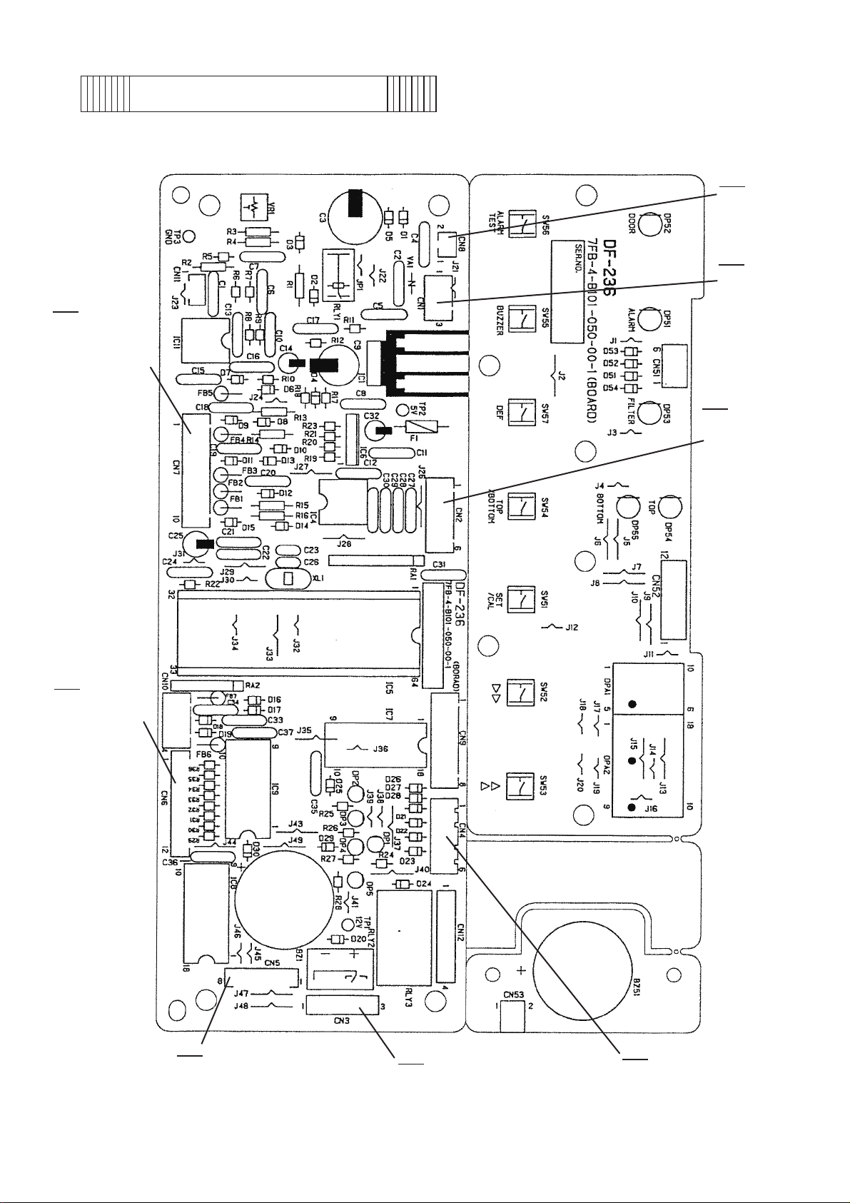
CN7
#3-#4
To Valve sensor
#9-#10
To Temp.sensor
Components on PCB
CN8
#1-#2
To Battery 6V
CN1
#1,#3
To Switching
power supply
CN2
#1-#6
To MTR-480
(Option)
CN6
#1-#12
To Display PCB
(CN52)
CN5
#1-#6
To Display PCB (CN51)
#7-#8
To Buzzer
CN3
#1-#3
To Remote alarm terminal
CN4
#1-#2
To Temp.control relay
#3-#4
To Solenoid valve relay
- 8 -
Page 12

Specifications of sensor
The following shows temperature and resistance characteristics on each thermistor sensor
(type 502AT-1).
Temperature
䋨㷄䋩
䋭50
䋭45
䋭40
䋭35
䋭30
䋭25
䋭20
䋭19
䋭18
䋭17
䋭16
䋭15
䋭14
Resistance
䋨k㱅䋩
154.50
116.50
88.85
68.15
52.84
41.19
32.43
30.92 0 13.29 19 6.24
29.50 1 12.74 20 6.01
28.14 2 12.22 25 5.00
26.87 3 11.72 30 4.18
25.65 4 11.25 35 3.51
24.51 5 10.80 40 2.96
Temperature
䋨㷄䋩
䋭7
䋭6
䋭5
䋭4
䋭3
䋭2
䋭1
Resistance
䋨k㱅䋩
17.92 12 8.17
17.16 13 7.85
16.43 14 7.55
15.74 15 7.27
15.08 16 6.99
14.45 17 6.73
13.86 18 6.48
Temperature
䋨㷄䋩
Resistance
䋨k㱅䋩
䋭13
䋭12
䋭11
䋭10
䋭9
䋭8
23.42 6 10.37 45 2.51
22.39 7 9.96 50 2.14
21.41 8 9.57 55 1.83
20.48 9 9.20 60 1.57
19.58 10 8.84
18.73 11 8.49
- 9 -
Page 13
Control specifications
㩷
1. Keys on control panel
BUZZER : When alarm lamp blinks and buzzer sounds, press this key to
stop buzzer and remote alarm operation.
When you set alarm resume time (except for 000) in F25, buzzer
will sound again after the time elapses.
: Buzzer does not activate during alarm test performs.
: When alarm lamp blinks and buzzer does not activate, buzzer
will not activate if you press BUZZER key.
: When you press this key during power failure, current chamber
temperature will be displayed for 5 seconds.
SET : Press this key to step to setting mode.
Press this key again to memorize setting value.
(It functions as ENTER key)
DEF : In chamber temperature displays, press this key for 5 seconds to
start defrosting with chamber temperature and ‘dF’ are displayed
alternately.
Press this key during defrost performs to come defrosting to end.
High/low temperature alarm will not activate during defrost
performs.
When sensor is failed during defrost performs, an error code and
chamber temperature are displayed alternately. (‘dF’ will be gone
off.)
During defrost performs, any keys but BUZZER are inoperative.
ALARM TEST : In chamber temperature displays, press this key to activate
alarm test mode.
Press the key again to stop ALARM TEST performing.
When BATTERY switch is ON position, press this key to blank
the display, ALARM lamp blinks and buzzer sounds.
When BATTERY switch is OFF position, press this key to display
“E09”, ALARM lamp blinks and buzzer sounds.
During alarm test performs, any keys but ALARM TEST key are
inoperative.
Digit shift key : Press this key is in setting mode that enables changeable digit to
shift. Press this key for 5 seconds to step to Key Lock mode. (‘L
0’ displays)
Numerical value
shift key :
Press this key in setting mode that enables numerical value to
shift. Press this key for 5 seconds to step to Key Lock mode. (‘L
0’ displays)
2. Temperature control, high & low temperature alarm
<Temperature control>
Setting range :
Display range :
How to set : Press SET key to set required value using with digit shift key and
-18㷄䌾-45㷄
-50㷄䌾+50㷄
numerical value shift key. Press SET key again to memorize the
value.
- 10 -
Page 14

Unacceptable setting : When you try to set value out of range and press SET key,
buzzer sounds for 1 second to inform the value is unacceptable
to set.
<Alarms>
High temperature alarm : When a chamber temperature is higher than setting temperature
+5㷄䌾+15㷄 (initial: +10㷄), ALARM lamp and digital display
blink. Buzzer sounds and remote alarm output activates with 15
minutes delay.
Low temperature alarm : When a chamber temperature is lower than setting temperature
-5㷄䌾-15㷄 (initial: -10㷄), ALARM lamp and digital display blink.
Buzzer sounds and remote alarm activates with 15 minutes
delay.
How to set : Press numerical value shift key for 5 seconds to step to Function
mode (“F00” displays). Set “ F01” by using numerical value shift
key for setting high temperature alarm, set “F02” for setting low
temperature alarm.
Press SET key and set a required value by numerical value shift
key and digit shift key.
Press SET key again to memorize the value.
Unacceptable setting : When you try to set value out of range and press SET key,
buzzer sounds for 1 second to inform the value is unacceptable
to set.
3. Defrosting
In chamber temperature display, press DEF key for 5 seconds to start defrosting.
Compressor and solenoid valve are inoperative during defrosting.
Press DEF key again to come defrosting to the end.
4. Error codes
Error code priority
High
Low
Note) “E09” and “Blank” are displayed during power failure.
E01 : Temperature sensor is disconnected.
“E01” and “-50㷄” are displayed alternately.
E02 : Temperature sensor is short circuited.
“E02” and “+50㷄” are displayed alternately.
E09 : BATTERY switch is off position.
“E09” is displayed if BATTERY switch is off poison when the
power is supplied.
E11 : Valve sensor is disconnected.
“E11” and “-50㷄” are displayed alternately.
E12 : Valve sensor is short circuited.
“E12” and “+50㷄” are displayed alternately.
- 11 -
Page 15

5. Key lock function
In chamber temperature display, press digit shift key for 5 seconds to step to Key Lock mode
with “L 0” displayed.
When you set to “1” by using numerical value shift key, Key Lock is ON.
Once Key Lock is ON, values are unchangeable, defrosting cannot be performed, while
Function mode is operative and ALARM test can be performed.
Press SET key to memorize value and unit returns to chamber temperature display.
When you set to “0” by using numerical value shift key, Key Lock is OFF.
Power failure alarm (buzzer and display are not operative without power supplied)
6.
When a power is failed, power failure alarm will be given by battery.
ALARM lamp will blink, digital display will go off, buzzer will sound intermittently and remote
alarm output will activate.
Buzzer will stop sounding if BUZZER key is pressed.
Press BUZZER key to show a current chamber temperature for 5 seconds.
Any keys but BUZZER key will be inoperative during power failure alarm.
7. Alarm test
This function is to ensure ALARM lamp, buzzer and remote alarm are workable.
In chamber temperature display, ALARM lamp will blink, buzzer will sound, remote alarm will
activate and digital display will go off when you press ALARM TEST key.
Any keys but ALARM TEST key will be inoperative during ALARM TEST is performed.
Note) E09 will be displayed even if other error code displays prior to perform alarm test.
8. Auto return function
If there are no key operations for 90 seconds in setting mode or key lock mode or function
mode, a value which will be set is not memorized and unit returns to chamber temperature
display.
9. Compressor delay time
In cycle operation, compressor will inactivate for 3 minutes since the compressor turns off.
When the power is supplied (micro computer is reset), compressor delay time is changeable
(3~15 minutes). See Function mode, ‘F05’ for details.
10. Function mode
F01: Setting of high temperature alarm
F02: Setting of low temperature alarm
F05: Setting of compressor delay time
F06: Setting of service code
F07: Zero calibration of temp. sensor
F12: Display of temperature of temp. sensor
F15: Display of temperature of valve sensor
F17: Check of model code
F21:
F22: Setting of communication mode
F25: Setting of alarm resume time
F32: Display of fan motor accumulation time
F45: Display of battery accumulation time
F46: Display of diagnosis value
Setting of communication ID (000䌾255)
- 12 -
Page 16

How to step to Function mode:
In chamber temperature display, press numerical value shift key for 5 seconds to step to
Function mode with “F00” displays. Input required function code by numerical value shift
key and press SET key.
F01: Setting of high temperature alarm
Setting range is +5㷄䌾+15㷄. (Initial: +10㷄)
F02: Setting of low temperature alarm
Setting range is -5㷄䌾-15㷄. (Initial: -10㷄)
F05: Setting of compressor delay time
This function is to reduce compressor start-up failure and breaker tripping which will be
caused after power failure.
Setting range is 3䌾15 minutes. (Initial: 3 minutes)
This function is active when the power is supplied (micro-computer is reset).
F06: Input service code ‘384’ by numerical value shift key and digit shift key, prior to perform
F07 or latter number function codes.
Press SET key to memorize the value.
You can change value for F21 and F22 without inputting service code.
Note) Service code will be memorized until you input “000” in F06 or the main power turns
off.
<Reset of battery accumulation time>
Input service code, ‘384’ then ‘409’ to reset battery accumulation time. Unit
automatically reverts to chamber temperature display.
<Reset of fan motor accumulation time>
Input service code, ‘384’ then ‘419’ to reset fan motor accmulation time. Unit
automatically reverts to chamber temperature display.
F07: Zero calibration of temp. sensor
Input service code “384” prior to use the function.
Setting range is -9.9㷄~+9.9㷄.
In “F07” display, press SET key to display “00.0” (initial value), and set temperature by
numerical value shift key and digit shift key.
Press SET key to memorize the value.
Zero calibration of temp. sensor is done by differential input.
Ex.)
When measured center temperature is –28.5㷄and display temperature is –30㷄, you
should add +1.5 to the value in F07. (Calculation: -28.5 – (-30))
F12: Display of temperature of temp. sensor
Input service code “384” prior to use the function.
Display range is -72.0~+83.0.
Decimal point is displayed but minus code, “-“ of a value which is equal or lower than
-20㷄 is not displayed.
Ex.)
Actual temperature: -35㷄 -> Displays as “35.0”
F15: Display of temperature of valve sensor
Input service code “384” prior to use the function.
Display range is -72.0~+163.
- 13 -
Page 17

F17: Check of model code
004: MDF-U5412
Input service code “384” prior to use the function.
In “F17” display, press SET key to display “001” (initial) and change the value by
numerical value shift key. Press SET key to memorize the value.
Initial setting values
Chamber temp
: -40㷄
Key lock mode : 0 (OFF)
High temp. alarm
Low temp. alarm
Zero calibration
: Set temperature +10㷄
: Set temperature -10㷄
: +0㷄 (for temp. sensor)
Compressor delay time : 0 minutes
Communication ID : 000
Communication mode : 000
Alarm resume time : 030 (30 minutes)
F21: Setting of serial communication ID
Settable range: 000䌾255 (000: No communication)
F22: Setting of serial communication mode
Control mode (The 3
1: Remote
Baud rate (The 2
rd
digit) 0: Local (Initial)
nd
digit) 0: 2400bps (Initial)
1: 4800bps
2: 9600bps
Note 1) The 1
st
digit is not used.
2) When you set mode in “Remote”, you cannot change chamber temperature and
perform defrosting in unit directly.
F25: Setting of alarm resume time
Settable range: 000, 010, 020, 030, 040, 050, 060 (000: Not resume)
F32: Display of condensing fan motor accumulation time
Input service code “384” prior to use the function.
Input F32 and press SET key to display F32 and “XX.X” (“00.0” will be displayed if the
accumulation time is less than a month) alternately.
Press SET key to return to chamber temperature display.
F45: Display of battery accumulation time
Input service code “384” prior to use the function.
Input F45 and press SET key to display F45 and “XX.X” (“00.0” will be displayed if the
accumulation time is less than a month) alternately.
Press SET key to return to chamber temperature display.
F46: Display of diagnosis temperature for valve control
Input service code “384” prior to use the function.
Input F46 and press SET key to display F46 and diagnosis temperature (-20.0~-40.0)
alternately.
Press SET key to return to chamber temperature display.
- 14 -
Page 18

11. Differential temperature
When chamber temperature is equal or higher than set temperature, it allows compressor to
activate.
When chamber temperature is equal or lower than set temperature – 0.6㷄, compressor will
be inoperative.
12. Remote alarm
In normal operation : Remote alarm contact is opened
In alarm or power failure : Remote alarm contact is closed
13. Solenoid valve
Solenoid valve is a magnetic valve which transfers gas to capillary tube that is located in the
center of evaporator.
(1) In condition that -18㷄҈SV (set temperature) 㻡-25㷄;
Solenoid valve will forcibly inactivate when PV (chamber temperature) - SV (set
temperature) +5㷄 ҈ 0
Ex. 1) SV(set temperature): -20㷄 PV(chamber temperature): -10㷄
(-10) – (-20) + 5 = 15 ……15 is higher than 0 => Solenoid valve inactivates forcibly
2) SV(set temperature): -20㷄 PV(chamber temperature): -30㷄
(-30) – (-20) + 5 = -5 …… -5 is lower than 0 => Solenoid valve activates
(2) Diagnosis value for valve operation
Solenoid valve is controlled with every 30 minutes by comparing diagnosis value with
SV(set temperature).
The comparison is done after 1 minute elapses since the unit was started.
In condition that AT(ambient temperature) 㻡18.0㷄, diagnosis value is -40.0㷄.
In condition that AT(ambient temperature) 䋾18.0㷄, diagnosis value is 0.6 x AT(ambient
temperature) – 51
In condition that AT(ambient temperature) 㻢 diagnosis value, solenoid valve is linked
with compressor. That is, solenoid valve transfers gas to the capillary tube when
compressor activates.
Ex. 1) AT(ambient temperature): 15㷄 SV(set temperature): -40㷄
Diagnosis value is -40.0㷄.
AT(ambient temperature) is higher than -40㷄(diagnosis value) so solenoid valve
links with compressor.
2) AT(ambient temperature): 20㷄 SV(set temperature): -35㷄
Diagnosis value is 0.6 x 20(AT) – 51 = -39
Diagnosis value (-39) is lower than -35(diagnosis value) so solenoid valve links
with compressor.
3) AT(ambient temperature): 35㷄 SV(set temperature): -35㷄
Diagnosis value is 0.6 x 35(AT) – 51 = -30
Diagnosis value (-30) is higher than -35(set temperature) so solenoid value does
not link with compressor. That is, solenoid valve does not transfer gas to the
capillary tube.
- 15 -
Page 19

(3) Summary
In condition of (1) (ambient temperature is equal or higher than set temperature + 6㷄),
solenoid valve forcibly activates.
In condition of (2), solenoid valve is controlled by diagnosis value to enable unit to reach
set temperature if both of capillary tube are used in high ambient temperature.
Solenoid valve is used to control chamber temperature uniformity in condition of higher
set temperature and to enable unit to reach set temperature in condition of higher
ambient temperature.
- 16 -
Page 20
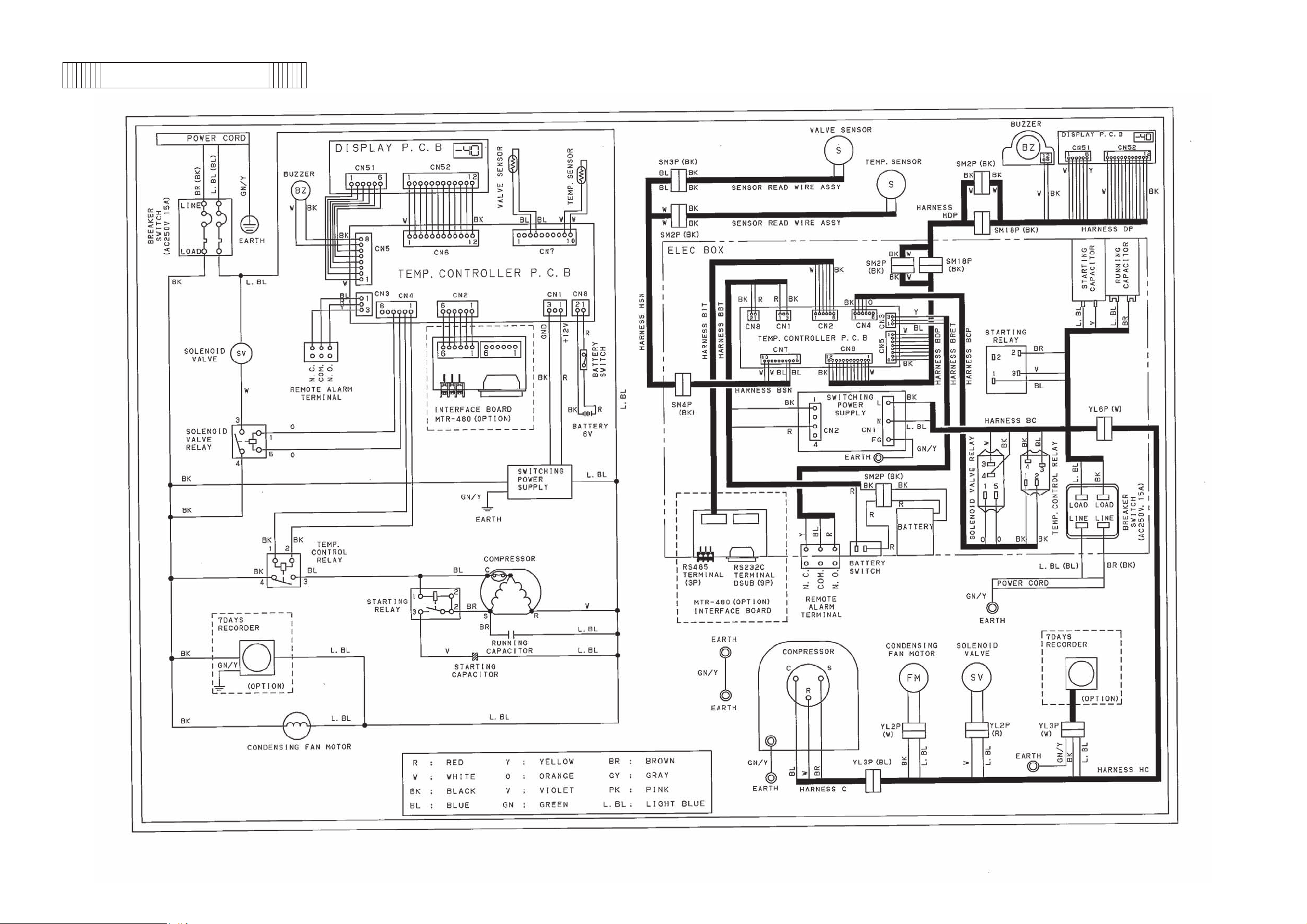
Wiring diagram
- 17 -
Page 21

Circuit diagram
- 18 -
Page 22

pp
g
(6p
)
ge(4p
)
>
Parts layout
<Front view>
<O
osite side of control panel>
Buzzer PCBDisplay PCB
<Screw holes to fix Temp. sensor>
e
Stora
container
small
cs.
Storage
container
lar
cs.
<Temp. sensor mounts on lowest shelf>
<Temp. sensor cover is removed
- 19 -
Page 23

Dry core ass'
y
p
(
)
y(
)
Solenoid valve Solenoid coil Condensing fan motor
ressor terminal
Com
<Back side bottom> <Terminal cover is removed>
Zoom-in
Compressor
Fan motor connection
Tube connect ass'
Check valve
- 20 -
Page 24

<Electric BOX on top of unit - Back side>
y
g
g
p
g
y
y
y
y
Remote alarm terminal Power cord
Batter
switch
Power switch
Startin
<Electric BOX> Runnin
.
Tem
controller
PCB Startin
Switchingpower suppl
Batter
Solenoid valve rela
<Temp. sensor wiring harness - Back side>
Temp. control relayBreaker switch
capacitor
capacitor
rela
- 21 -
Page 25

Test data
40.0
]
30.0
㷄
20.0
10.0
0.0
-10.0
-20.0
-30.0
1/2 chamber air temp.[
-40.0
-50.0
024681012
*All the data are the reference only.
Pull-down characteristics
AT 30㷄, no-load
50Hz230V
60Hz220V
Time scale[h]
Pull-up characteristics
AT30㷄, no-load
20
]
10
㷄
0
-10
-20
-30
-40
1/2 chamber air temp. [
-50
024681012
Time scale[h]
- 22 -
Page 26

Pull-down pressure
AT 30㷄, no-load
㪉
㪈㪅㪏
㪈㪅㪍
㪈㪅㪋
㪈㪅㪉
㪈
㪇㪅㪏
Pressure[MPa]
㪇㪅㪍
㪇㪅㪋
㪇㪅㪉
㪇
024681012
㪌㪇㪟㫑㪉㪊㪇㪭㩷㪧㪻㫀㫊 㪍㪇㪟㫑㪉㪉㪇㪭㩷㪧㪻㫀㫊
㪌㪇㪟㫑㪉㪊㪇㪭㩷㪧㫊㫌㪺 㪍㪇㪟㫑㪉㪉㪇㪭㩷㪧㫊㫌㪺
Time scale[h]
Pull-down power consumption & current
AT 30㷄, no-load
3.5
3
2.5
2
1.5
1
Current value[A]
0.5
0
50Hz230V A 60Hz220V A
50Hz230V W 60Hz220V W
0123467891011
Time scale[h]
350
300
250
200
150
100
Power consumption[W]
50
0
- 23 -
Page 27

Temperature uniformity (15 points measured)
㪁㪛㪸㫋㪸㩷㪸㫉㪼㩷㫋㪿㪼㩷㫉㪼㪽㪼㫉㪼㫅㪺㪼㩷㫆㫅㫃㫐㪅
㪓㪫㪼㫊㫋㩷㪺㫆㫅㪻㫀㫋㫀㫆㫅㫊㪕
T20㷄, No load
<Measured points>
50mm upper from bottom
of 3rd level container
50mm lower from top
edge of upper container
㩷㪈
㩷㪉
㩷㪊
㩷㪋
㩷㪌
㩷㪎
㩷㪍
㩷㪏
㩷㪐
㩷㪈㪇
㩷㪈㪈
㩷㪈㪉
㩷㪈㪊
㩷㪈㪋
㩷㪈㪌
<Measured points>
* Upper : 50mm lower from top of top container
䍃Center (㽴)
䍃Corner (㽲,㽳,㽵,㽶)
* Middle: 50mm upper from bottom of 3rd stage container
䍃Center, 1/2H (㽹)
䍃Corner (㽷,㽸,㽺,㽻)
*Lower: 50mm upper from bottom of bottom container
䍃Center (㽾)
䍃Corner (㽼,㽽,㽿,㾀)
50
50mm
10
50
50
50mm upper from bottom
of bottom container
Corner
Center
- 24 -
Page 28

<Temperature uniformity>
㷄
e
y
㷄
㷄
e
y
㷄
㫐
㫐
㫐
㫐
㫐
㫐
SV-30
㪌㪇㪟㫑 㪍㪇㪟㫑
㪤㪸㫏㫀㫄 㫌㫄 㪤㫀㫅㫀㫄㫌㫄
㽲 㪄㪉㪎㪅㪎 㪄㪊㪇㪅㪎 㪄㪉㪐㪅㪉 㫧㪈㪅㪌 㪄㪉㪎㪅㪌 㪄㪊㪇㪅㪋 㪄㪉㪐㪅㪇 㫧㪈㪅㪌
㽳 㪄㪉㪍㪅㪌 㪄㪊㪇㪅㪇 㪄㪉㪏㪅㪊 㫧㪈㪅㪏 㪄㪉㪍㪅㪎 㪄㪉㪐㪅㪎 㪄㪉㪏㪅㪉 㫧㪈㪅㪌
㽴 㪄㪉㪎㪅㪋 㪄㪉㪐㪅㪍 㪄㪉㪏㪅㪌 㫧㪈㪅㪈 㪄㪉㪎㪅㪍 㪄㪉㪐㪅㪍 㪄㪉㪏㪅㪍 㫧㪈㪅㪇
㽵 㪄㪉㪍㪅㪎 㪄㪉㪐㪅㪊 㪄㪉㪏㪅㪇 㫧㪈㪅㪊 㪄㪉㪍㪅㪉 㪄㪉㪏㪅㪎 㪄㪉㪎㪅㪌 㫧㪈㪅㪊
㽶 㪄㪉㪌㪅㪐 㪄㪉㪏㪅㪍 㪄㪉㪎㪅㪊 㫧㪈㪅㪋 㪄㪉㪍㪅㪇 㪄㪉㪏㪅㪎 㪄㪉㪎㪅㪋 㫧㪈㪅㪋
㽷 㪄㪉㪐㪅㪍 㪄㪊㪈㪅㪍 㪄㪊㪇㪅㪍 㫧㪈㪅㪇 㪄㪉㪐㪅㪏 㪄㪊㪈㪅㪍 㪄㪊㪇㪅㪎 㫧㪇㪅㪐
㽸 㪄㪉㪐㪅㪊 㪄㪊㪈㪅㪏 㪄㪊㪇㪅㪍 㫧㪈㪅㪊 㪄㪉㪐㪅㪌 㪄㪊㪈㪅㪎 㪄㪊㪇㪅㪍 㫧㪈㪅㪈
㽹 㪄㪊㪇㪅㪇 㪄㪊㪉㪅㪎 㪄㪊㪈㪅㪋 㫧㪈㪅㪋 㪄㪊㪇㪅㪋 㪄㪊㪉㪅㪉 㪄㪊㪈㪅㪊 㫧㪇㪅㪐
㽺 㪄㪉㪏㪅㪍 㪄㪊㪇㪅㪉 㪄㪉㪐㪅㪋 㫧㪇㪅㪏 㪄㪉㪐㪅㪇 㪄㪉㪐㪅㪉 㪄㪉㪐㪅㪈 㫧㪇㪅㪈
㽻 㪄㪉㪎㪅㪏 㪄㪉㪐㪅㪏 㪄㪉㪏㪅㪏 㫧㪈㪅㪇 㪄㪉㪐㪅㪈 㪄㪊㪇㪅㪍 㪄㪉㪐㪅㪐 㫧㪇㪅㪏
㽼 㪄㪉㪎㪅㪈 㪄㪉㪏㪅㪐 㪄㪉㪏㪅㪇 㫧㪇㪅㪐 㪄㪉㪎㪅㪌 㪄㪉㪐㪅㪈 㪄㪉㪏㪅㪊 㫧㪇㪅㪏
㽽 㪄㪉㪎㪅㪌 㪄㪉㪐㪅㪉 㪄㪉㪏㪅㪋 㫧㪇㪅㪐 㪄㪉㪎㪅㪉 㪄㪉㪐㪅㪇 㪄㪉㪏㪅㪈 㫧㪇㪅㪐
㽾 㪄㪉㪏㪅㪊 㪄㪊㪇㪅㪊 㪄㪉㪐㪅㪊 㫧㪈㪅㪇 㪄㪉㪏㪅㪇 㪄㪉㪐㪅㪎 㪄㪉㪏㪅㪐 㫧㪇㪅㪐
㽿 㪄㪉㪎㪅㪍 㪄㪉㪐㪅㪍 㪄㪉㪏㪅㪍 㫧㪈㪅㪇 㪄㪉㪎㪅㪇 㪄㪉㪏㪅㪌 㪄㪉㪎㪅㪏 㫧㪇㪅㪏
㾀 㪄㪉㪏㪅㪇 㪄㪊㪇㪅㪊 㪄㪉㪐㪅㪉 㫧㪈㪅㪉 㪄㪉㪎㪅㪏 㪄㪉㪐㪅㪐 㪄㪉㪏㪅㪐 㫧㪈㪅㪈
㪘㫍㪼㫉㪸㪾㪼 㪄 㪄 㪄㪉㪐㪅㪇 㪄 㪄 㪄 㪄㪉㪏㪅㪐 㪄
㪘㫄㪹㫀㪼㫅㫋㩷㫋㪼㫄㫇㪼㫉㪸㫋㫌㫉㪼㩷㪉㪇㷄
㪤㫀㪻㪻㫃㪼㩷㫆㪽
㪛㫀㪽㪽㪼㫉㪼㫅㫋㫀㪸㫃 㪤㪸㫏㫀㫄㫌㫄 㪤㫀㫅㫀㫄㫌㫄
㪺
㪺㫃㪼
(Unit䋺㷄䋩
㪤㫀㪻㪻 㫃㪼㩷㫆㪽
㪺㫐㪺㫃㪼
㪛㫀㪽㪽㪼㫉㪼㫅㫋㫀㪸㫃
䋼Amount of power consumption䋾
Amount of power consumption when driving at cycl
Unit䋺kWh/da
Ambient temperature 20㷄
SV-30㷄 SV-40㷄
50Hz 60Hz 50Hz 60Hz
220V 3.66 2.62 4.51 3.39
230V 3.74 - 4.84 240V 3.93 - 5.63 -
SV-40
(Unit䋺㷄䋩
㪘㫄㪹㫀㪼㫅㫋㩷㫋㪼㫄㫇㪼㫉㪸㫋㫌㫉㪼㩷㪉㪇㷄
㪌㪇㪟㫑 㪍㪇㪟㫑
㪤㪸㫏㫀㫄 㫌㫄 㪤㫀㫅㫀㫄㫌㫄
㽲 㪄㪊㪎㪅㪈 㪄㪊㪐㪅㪍 㪄㪊㪏㪅㪋 㫧㪈㪅㪊 㪄㪊㪍㪅㪐 㪄㪊㪐㪅㪎 㪄㪊㪏㪅㪊 㫧㪈㪅㪋
㪤㫀㪻㪻㫃㪼㩷㫆㪽
㪺
㪺㫃㪼
㪛㫀㪽㪽㪼㫉㪼㫅㫋㫀㪸㫃 㪤㪸㫏㫀㫄㫌㫄 㪤㫀㫅㫀㫄㫌㫄
㪤㫀㪻㪻 㫃㪼㩷㫆㪽
㪺㫐㪺㫃㪼
㪛㫀㪽㪽㪼㫉㪼㫅㫋㫀㪸㫃
㽳 㪄㪊㪌㪅㪎 㪄㪊㪏㪅㪋 㪄㪊㪎㪅㪈 㫧㪈㪅㪋 㪄㪊㪌㪅㪌 㪄㪊㪏㪅㪉 㪄㪊㪍㪅㪐 㫧㪈㪅㪋
㽴 㪄㪊㪍㪅㪎 㪄㪊㪏㪅㪍 㪄㪊㪎㪅㪎 㫧㪇㪅㪐 㪄㪊㪍㪅㪏 㪄㪊㪏㪅㪐 㪄㪊㪎㪅㪐 㫧㪈㪅㪈
㽵 㪄㪊㪍㪅㪈 㪄㪊㪏㪅㪋 㪄㪊㪎㪅㪊 㫧㪈㪅㪉 㪄㪊㪌㪅㪌 㪄㪊㪏㪅㪇 㪄㪊㪍㪅㪏 㫧㪈㪅㪊
㽶 㪄㪊㪋㪅㪐 㪄㪊㪎㪅㪉 㪄㪊㪍㪅㪈 㫧㪈㪅㪉 㪄㪊㪌㪅㪇 㪄㪊㪎㪅㪋 㪄㪊㪍㪅㪉 㫧㪈㪅㪉
㽷 㪄㪊㪐㪅㪊 㪄㪋㪈㪅㪋 㪄㪋㪇㪅㪋 㫧㪈㪅㪈 㪄㪊㪐㪅㪎 㪄㪋㪈㪅㪍 㪄㪋㪇㪅㪎 㫧㪇㪅㪐
㽸 㪄㪊㪐㪅㪇 㪄㪋㪈㪅㪋 㪄㪋㪇㪅㪉 㫧㪈㪅㪉 㪄㪊㪐㪅㪌 㪄㪋㪈㪅㪏 㪄㪋㪇㪅㪎 㫧㪈㪅㪉
㽹 㪄㪊㪐㪅㪐 㪄㪋㪉㪅㪋 㪄㪋㪈㪅㪉 㫧㪈㪅㪊 㪄㪋㪇㪅㪋 㪄㪋㪉㪅㪋 㪄㪋㪈㪅㪋 㫧㪈㪅㪇
㽺 㪄㪊㪎㪅㪐 㪄㪊㪏㪅㪍 㪄㪊㪏㪅㪊 㫧㪇㪅㪋 㪄㪊㪏㪅㪏 㪄㪊㪐㪅㪍 㪄㪊㪐㪅㪉 㫧㪇㪅㪋
㽻 㪄㪊㪎㪅㪌 㪄㪊㪐㪅㪍 㪄㪊㪏㪅㪍 㫧㪈㪅㪈 㪄㪊㪏㪅㪏 㪄㪋㪇㪅㪌 㪄㪊㪐㪅㪎 㫧㪇㪅㪐
㽼 㪄㪊㪍㪅㪈 㪄㪊㪎㪅㪍 㪄㪊㪍㪅㪐 㫧㪇㪅㪏 㪄㪊㪍㪅㪌 㪄㪊㪏㪅㪇 㪄㪊㪎㪅㪊 㫧㪇㪅㪏
㽽 㪄㪊㪍㪅㪏 㪄㪊㪏㪅㪊 㪄㪊㪎㪅㪍 㫧㪇㪅㪏 㪄㪊㪍㪅㪌 㪄㪊㪏㪅㪇 㪄㪊㪎㪅㪊 㫧㪇㪅㪏
㽾 㪄㪊㪎㪅㪍 㪄㪊㪐㪅㪈 㪄㪊㪏㪅㪋 㫧㪇㪅㪏 㪄㪊㪎㪅㪊 㪄㪊㪏㪅㪏 㪄㪊㪏㪅㪈 㫧㪇㪅㪏
㽿 㪄㪊㪎㪅㪇 㪄㪊㪏㪅㪏 㪄㪊㪎㪅㪐 㫧㪇㪅㪐 㪄㪊㪍㪅㪇 㪄㪊㪎㪅㪋 㪄㪊㪍㪅㪎 㫧㪇㪅㪎
㾀 㪄㪊㪎㪅㪋 㪄㪊㪐㪅㪉 㪄㪊㪏㪅㪊 㫧㪇㪅㪐 㪄㪊㪎㪅㪈 㪄㪊㪏㪅㪏 㪄㪊㪏㪅㪇 㫧㪇㪅㪏
㪘㫍㪼㫉㪸㪾㪼 㪄 㪄 㪄㪊㪏㪅㪊 㪄 㪄 㪄 㪄㪊㪏㪅㪊 㪄
SV-30
(Unit䋺㷄䋩
㪘㫄㪹㫀㪼㫅㫋㩷㫋㪼㫄㫇㪼㫉㪸㫋㫌㫉㪼㩷㪊㪇㷄
㪌㪇㪟㫑 㪍㪇㪟㫑
㪤㪸㫏㫀㫄㫌㫄 㪤㫀㫅㫀㫄㫌㫄
㽲 㪄㪉㪎㪅㪈 㪄㪊㪇㪅㪇 㪄㪉㪏㪅㪍 㫧㪈㪅㪌 㪄㪉㪎㪅㪇 㪄㪉㪐㪅㪏 㪄㪉㪏㪅㪋 㫧㪈㪅㪋
㪤㫀㪻 㪻㫃㪼㩷㫆㪽
㪺㫃㪼
㪺
㪛㫀㪽㪽㪼㫉㪼㫅㫋㫀㪸㫃 㪤㪸㫏 㫀㫄㫌㫄 㪤㫀㫅㫀㫄㫌㫄
㪤㫀㪻㪻㫃㪼㩷㫆㪽
㪺㫃㪼
㪺
㪛㫀㪽㪽㪼㫉㪼㫅㫋㫀㪸㫃
㽳 㪄㪉㪌㪅㪐 㪄㪉㪐㪅㪈 㪄㪉㪎㪅㪌 㫧㪈㪅㪍 㪄㪉㪍㪅㪈 㪄㪉㪐㪅㪈 㪄㪉㪎㪅㪍 㫧㪈㪅㪌
㽴 㪄㪉㪍㪅㪏 㪄㪉㪏㪅㪐 㪄㪉㪎㪅㪐 㫧㪈㪅㪈 㪄㪉㪎㪅㪉 㪄㪉㪐㪅㪈 㪄㪉㪏㪅㪉 㫧㪈㪅㪇
㽵 㪄㪉㪍㪅㪈 㪄㪉㪏㪅㪋 㪄㪉㪎㪅㪊 㫧㪈㪅㪉 㪄㪉㪌㪅㪎 㪄㪉㪏㪅㪊 㪄㪉㪎㪅㪇 㫧㪈㪅㪊
㽶 㪄㪉㪌㪅㪉 㪄㪉㪎㪅㪐 㪄㪉㪍㪅㪍 㫧㪈㪅㪋 㪄㪉㪌㪅㪌 㪄㪉㪏㪅㪉 㪄㪉㪍㪅㪐 㫧㪈㪅㪋
㽷 㪄㪉㪐㪅㪊 㪄㪊㪈㪅㪉 㪄㪊㪇㪅㪊 㫧㪇㪅㪐 㪄㪉㪐㪅㪏 㪄㪊㪈㪅㪌 㪄㪊㪇㪅㪎 㫧㪇㪅㪐
㽸 㪄㪉㪏㪅㪐 㪄㪊㪈㪅㪉 㪄㪊㪇㪅㪈 㫧㪈㪅㪉 㪄㪉㪐㪅㪋 㪄㪊㪈㪅㪌 㪄㪊㪇㪅㪌 㫧㪈㪅㪈
㽹 㪄㪉㪐㪅㪏 㪄㪊㪉㪅㪈 㪄㪊㪈㪅㪇 㫧㪈㪅㪉 㪄㪊㪇㪅㪋 㪄㪊㪉㪅㪊 㪄㪊㪈㪅㪋 㫧㪇㪅㪐
㽺 㪄㪉㪏㪅㪈 㪄㪉㪐㪅㪈 㪄㪉㪏㪅㪍 㫧㪇㪅㪌 㪄㪉㪏㪅㪏 㪄㪉㪏㪅㪐 㪄㪉㪏㪅㪐 㫧㪇㪅㪇
㽻 㪄㪉㪎㪅㪈 㪄㪉㪐㪅㪈 㪄㪉㪏㪅㪈 㫧㪈㪅㪇 㪄㪉㪐㪅㪇 㪄㪊㪇㪅㪌 㪄㪉㪐㪅㪏 㫧㪇㪅㪏
㽼 㪄㪉㪍㪅㪋 㪄㪉㪏㪅㪇 㪄㪉㪎㪅㪉 㫧㪇㪅㪏 㪄㪉㪍㪅㪏 㪄㪉㪏㪅㪊 㪄㪉㪎㪅㪍 㫧㪇㪅㪏
㽽 㪄㪉㪍㪅㪎 㪄㪉㪏㪅㪊 㪄㪉㪎㪅㪌 㫧㪇㪅㪏 㪄㪉㪍㪅㪌 㪄㪉㪏㪅㪉 㪄㪉㪎㪅㪋 㫧㪇㪅㪐
㽾 㪄㪉㪎㪅㪍 㪄㪉㪐㪅㪌 㪄㪉㪏㪅㪍 㫧㪇㪅㪐 㪄㪉㪎㪅㪌 㪄㪉㪐㪅㪉 㪄㪉㪏㪅㪋 㫧㪇㪅㪐
㽿 㪄㪉㪍㪅㪏 㪄㪉㪏㪅㪏 㪄㪉㪎㪅㪏 㫧㪈㪅㪇 㪄㪉㪍㪅㪉 㪄㪉㪎㪅㪏 㪄㪉㪎㪅㪇 㫧㪇㪅㪏
㾀 㪄㪉㪎㪅㪊 㪄㪉㪐㪅㪌 㪄㪉㪏㪅㪋 㫧㪈㪅㪈 㪄㪉㪎㪅㪈 㪄㪉㪐㪅㪉 㪄㪉㪏㪅㪉 㫧㪈㪅㪈
㪘㫍㪼㫉㪸㪾㪼 㪄 㪄 㪄㪉㪏㪅㪊 㪄 㪄 㪄 㪄㪉㪏㪅㪌 㪄
䋼Amount of power consumption䋾
Amount of power consumption when driving at cycl
Unit䋺kWh/da
㪘㫄㪹㫀㪼㫅㫋㩷㫋㪼㫄㫇㪼㫉㪸㫋㫌㫉㪼㩷㪊㪇㷄
㪪㪭㪄㪊㪇㷄 㪪㪭㪄㪋㪇㷄
㪌㪇㪟㫑 㪍㪇㪟㫑 㪌㪇㪟㫑 㪍㪇㪟㫑
㪉㪉㪇㪭 㪌㪅㪈㪋 㪊㪅㪊㪐 㪌㪅㪏㪐 㪋㪅㪌㪍
㪉㪊㪇㪭 㪌㪅㪊㪐 㪄 㪍㪅㪋㪉 㪄
㪉㪋㪇㪭 㪌㪅㪐㪈 㪄 㪍㪅㪐㪉 㪄
SV-40
(Unit䋺㷄䋩
㪘㫄㪹㫀㪼㫅㫋㩷㫋㪼㫄㫇㪼㫉㪸㫋㫌㫉㪼㩷㪊㪇㷄
㪌㪇㪟㫑 㪍㪇㪟㫑
㪤㪸㫏㫀㫄㫌㫄 㪤㫀㫅㫀㫄㫌㫄
㽲 㪄㪊㪍㪅㪌 㪄㪊㪏㪅㪏 㪄㪊㪎㪅㪎 㫧㪈㪅㪉 㪄㪊㪍㪅㪋 㪄㪊㪐㪅㪇 㪄㪊㪎㪅㪎 㫧㪈㪅㪊
㪤㫀㪻㪻㫃㪼㩷㫆㪽
㪺㫃㪼
㪺
㪛㫀㪽㪽㪼㫉㪼㫅㫋㫀㪸㫃 㪤 㪸㫏㫀㫄㫌㫄 㪤㫀㫅㫀㫄㫌㫄
㪤㫀㪻㪻 㫃㪼㩷㫆㪽
㪺㫃㪼
㪺
㪛㫀㪽㪽㪼㫉㪼㫅㫋㫀㪸㫃
㽳 㪄㪊㪋㪅㪏 㪄㪊㪎㪅㪍 㪄㪊㪍㪅㪉 㫧㪈㪅㪋 㪄㪊㪌㪅㪌 㪄㪊㪎㪅㪐 㪄㪊㪍㪅㪎 㫧㪈㪅㪉
㽴 㪄㪊㪍㪅㪇 㪄㪊㪎㪅㪐 㪄㪊㪎㪅㪇 㫧㪇㪅㪐 㪄㪊㪍㪅㪍 㪄㪊㪏㪅㪎 㪄㪊㪎㪅㪎 㫧㪈㪅㪈
㽵 㪄㪊㪌㪅㪊 㪄㪊㪎㪅㪍 㪄㪊㪍㪅㪌 㫧㪈㪅㪉 㪄㪊㪌㪅㪇 㪄㪊㪎㪅㪌 㪄㪊㪍㪅㪊 㫧㪈㪅㪊
㽶 㪄㪊㪋㪅㪈 㪄㪊㪍㪅㪌 㪄㪊㪌㪅㪊 㫧㪈㪅㪉 㪄㪊㪋㪅㪎 㪄㪊㪎㪅㪉 㪄㪊㪍㪅㪇 㫧㪈㪅㪊
㽷 㪄㪊㪐㪅㪈 㪄㪋㪈㪅㪊 㪄㪋㪇㪅㪉 㫧㪈㪅㪈 㪄㪊㪐㪅㪍 㪄㪋㪈㪅㪌 㪄㪋㪇㪅㪍 㫧㪇㪅㪐
㽸 㪄㪊㪏㪅㪐 㪄㪋㪈㪅㪈 㪄㪋㪇㪅㪇 㫧㪈㪅㪈 㪄㪊㪐㪅㪌 㪄㪋㪈㪅㪎 㪄㪋㪇㪅㪍 㫧㪈㪅㪈
㽹 㪄㪊㪐㪅㪐 㪄㪋㪉㪅㪈 㪄㪋㪈㪅㪇 㫧㪈㪅㪈 㪄㪋㪇㪅㪋 㪄㪋㪉㪅㪊 㪄㪋㪈㪅㪋 㫧㪇㪅㪐
㽺 㪄㪊㪎㪅㪏 㪄㪊㪏㪅㪈 㪄㪊㪏㪅㪇 㫧㪇㪅㪉 㪄㪊㪏㪅㪏 㪄㪋㪇㪅㪇 㪄㪊㪐㪅㪋 㫧㪇㪅㪍
㽻 㪄㪊㪎㪅㪊 㪄㪊㪐㪅㪌 㪄㪊㪏㪅㪋 㫧㪈㪅㪈 㪄㪊㪏㪅㪏 㪄㪋㪇㪅㪋 㪄㪊㪐㪅㪍 㫧㪇㪅㪏
㽼 㪄㪊㪌㪅㪍 㪄㪊㪎㪅㪇 㪄㪊㪍㪅㪊 㫧㪇㪅㪎 㪄㪊㪍㪅㪈 㪄㪊㪎㪅㪍 㪄㪊㪍㪅㪐 㫧㪇㪅㪏
㽽 㪄㪊㪍㪅㪍 㪄㪊㪏㪅㪈 㪄㪊㪎㪅㪋 㫧㪇㪅㪏 㪄㪊㪍㪅㪈 㪄㪊㪎㪅㪌 㪄㪊㪍㪅㪏 㫧㪇㪅㪎
㽾 㪄㪊㪎㪅㪋 㪄㪊㪏㪅㪐 㪄㪊㪏㪅㪉 㫧㪇㪅㪏 㪄㪊㪎㪅㪈 㪄㪊㪏㪅㪍 㪄㪊㪎㪅㪐 㫧㪇㪅㪏
㽿 㪄㪊㪍㪅㪐 㪄㪊㪏㪅㪍 㪄㪊㪎㪅㪏 㫧㪇㪅㪐 㪄㪊㪌㪅㪌 㪄㪊㪍㪅㪐 㪄㪊㪍㪅㪉 㫧㪇㪅㪎
㾀 㪄㪊㪎㪅㪉 㪄㪊㪏㪅㪏 㪄㪊㪏㪅㪇 㫧㪇㪅㪏 㪄㪊㪍㪅㪏 㪄㪊㪏㪅㪌 㪄㪊㪎㪅㪎 㫧㪇㪅㪐
㪘㫍㪼㫉㪸㪾㪼 㪄 㪄 㪄㪊㪎㪅㪏 㪄 㪄 㪄 㪄㪊㪏㪅㪈 㪄
Note:This data does not represent a guarantee of product performance.
- 25 -
Page 29

Temperatures during cycle 䋨50Hz230V䋩
AT 30㷄䋬No load
㪄㪉㪌
SV= -30㷄 SV= -35㷄 SV= -40㷄
㪄㪊㪇
]
㷄
㪄㪊㪌
Temperature[
㪄㪋㪇
㪄㪋㪌
0 20 40 60 80 100 120 140 160 180
Time [min]
Temperatures during cycle 䋨60Hz220V䋩
AT 30㷄䋬No load
-25
SV= -30㷄 SV= -35㷄 SV= -40㷄
-30
]
㷄
-35
Temperature [
-40
-45
0 20 40 60 80 100 120 140 160 180
Time [min]
Note:This data does not represent a guarantee of product performance.
- 26 -
Page 30

Instruction manual
䊶㩷This section is extracted and printed from Instruction Manual.
䊶㩷If you find out “Refer to page 䃂䃂” in them, this page means not page in Service manual
but page in the lower corner of each page in the extract from Instruction Manual.
This page number is not corresponded with serial number in Service manual.
䊶㩷Please note the extracted Instruction Manual which corresponds to the initial unit
production, so the contents may be revised in future.
- 27 -
Page 31

INSTRUCTION MANUAL
BIOMEDICAL FREEZER
MDF-U5412
- 28 -
Page 32

CONTENTS
INTRODUCTION P. 2
PRECAUTIONS FOR SAFE OPERATION P. 3
ENVIRONMENTAL CONDITIONS P. 7
FREEZER COMPONENTS P. 8
Control panel P.10
INSTALLATION SITE P.11
INSTALLATION P.12
START-UP OF UNIT P.13
TEMPERATURE SETTING P.14
Key lock function P.14
ALARM TEMPERATURE SETTING P.15
SETTING OF ALARM RESUME TIME P.16
REMOTE ALARM TERMINAL P.17
ALARMS & SAFETY FUNCTIONS P.18
ROUTINE MAINTENANCE
Cleaning of cabinet P.19
Defrosting P.19
REPLACEMENT OF BATTERY P.20
TROUBLESHOOTING P.21
DISPOSAL OF UNIT P.22
Recycle of battery P.22
TEMPERATURE RECORDER (OPTION)
Setting of MTR-4015LH P.27
Installation of MTR-4015LH P.29
Installation of MTR-G85 P.30
SPECIFICATIONS P.31
PERFORMANCE P.31
SAFETY CHECK SHEET P.32
1
- 29 -
Page 33

INTRODUCTION
Ŷ Read this manual carefully before using the appliance and follow the instructions for safety operation.
Ŷ Sanyo never guarantee any safety if the appliance is used for any objects other than intended use or
used by any procedures other than those mentioned in this manual.
Ŷ Keep this manual in an adequate place to refer to it as necessary.
Ŷ The contents of the manual will be subjected to change without notice due to the improvement of
performance or functions.
Ŷ Contact Sanyo sales representative or agent if any page of the manual is lost or page order is incorrect.
Ŷ Contact Sanyo sales representative or agent if any point in this manual is unclear or if there are any
inaccuracies.
Ŷ No part of this manual may be reproduced in any form without the expressed written permission of
Sanyo.
CAUTION
SANYO guarantees the product under certain warranty conditions. SANYO in no way shall be
responsible for any loss of content or damage of content.
- 30 -
2
Page 34

PRECAUTIONS FOR SAFE OPERATION
It is imperative that the user complies with this manual as it contains
important safety advice.
Items and procedures are described so that you can use this unit correctly and safely.
If the precautions advised are followed, this will prevent possible injury to the user and
any other person.
Precautions are illustrated in the following way:
WARNING
Failure to observe WARNING signs could result in a hazard to personnel
possibly resulting in serious injury or death.
CAUTION
Failure to observe CAUTION signs could result in injury to personnel and
damage to the unit and associated property.
Symbol shows;
this symbol means caution.
㩷
this symbol means an action is prohibited.
㩷
this symbol means an instruction must be followed.
㩷
Be sure to keep this manual in a place accessible to users of this unit.
< Label on the unit >
This mark is labeled on the cover in which the electrical components of high voltage are
enclosed to prevent the electric shock.
The cover should be removed by a qualified engineer or a service personnel only.
.
3
- 31 -
Page 35

PRECAUTIONS FOR SAFE OPERATION
WARNING
Do not use the unit outdoors. Current leakage or electric shock may result if the unit is exposed to
rain water.
Only qualified engineers or service personnel should install the unit. The installation by
unqualified personnel may cause electric shock or fire.
Install the unit on a sturdy floor and take an adequate precaution to prevent the unit from
turning over. If the floor is not strong enough or the installation site is not adequate, this may result
in injury from the unit falling or tipping over.
Never install the unit in a humid place or a place where it is likely to be splashed by water.
Deterioration of the insulation may result which could cause current leakage or electric shock.
Never install the unit in a flammable or volatile location. This may cause explosion or fire.
Never install the unit where acid or corrosive gases are present as current leakage or electric
shock may result due to corrosion.
Always ground (earth) the unit to prevent electric shock. If the power supply outlet is not
grounded, it will be necessary to install a ground by qualified engineers.
Never ground the unit through a gas pipe, water main, telephone line or lightning rod. Such
grounding may cause electric shock in the case of an incomplete circuit.
Connect the unit to a power source as indicated on the rating label attached to the unit. Use of
any other voltage or frequency other than that on the rating label may cause fire or electric shock.
Never store volatile or flammable substances in this unit if the container cannot be sealed. These
may cause explosion or fire.
Do not insert metal objects such as a pin or a wire into any vent, gap or any outlet on the unit.
This may cause electric shock or injury by accidental contact with moving parts.
Use this unit in safe area when treating the poison, harmful or radiate articles. Improper use
may cause bad effect on your health or environment.
Turn off the power switch (if provided) and disconnect the power supply to the unit prior to any
repair or maintenance of the unit in order to prevent electric shock or injury.
Do not touch any electrical parts (such as power supply plug) or operate switches with a wet
hand. This may cause electric shock.
- 32 -
4
Page 36

PRECAUTIONS FOR SAFE OPERATION
WARNING
Ensure you do not inhale or consume medication or aerosols from around the unit at the time of
maintenance. These may be harmful to your health.
Never splash water directly onto the unit as this may cause electric shock or short circuit.
Never put containers with liquid on the unit as this may cause electric shock or short circuit when
the liquid is spilled.
Never bind, process, or step on the power supply cord, or never damage or break the power
supply plug. A broken supply cord or plug may cause fire or electric shock.
Do not use the supply cord if its plug is loose. Such supply cord may cause fire or electric shock.
Never disassemble, repair, or modify the unit yourself. Any such work carried out by an
unauthorized person may result in fire, or electric shock or injury due to a malfunction.
Disconnect the power supply plug if there is something wrong with the unit. Continued
abnormal operation may cause electric shock or fire.
When removing the plug from the power supply outlet, grip the power supply plug, not the cord.
Pulling the cord may result in electric shock or fire by short circuit.
Disconnect the power supply plug before moving the unit. Take care not to damage the power
cord. A damaged cord may cause electric shock or fire.
Disconnect the power plug when the unit is not used for long periods. Keeping the connection
may cause electric shock, current leakage, or fire due to the deterioration of insulation.
If the unit is to be stored unused in an unsupervised area for an extended period, ensure that children
do not have access and that doors cannot be closed completely.
The disposal of the unit should be accomplished by appropriate personnel. Remove doors to
prevent accidents such as suffocation.
Do not put the packing plastic bag within reach of children as suffocation may result.
5
- 33 -
Page 37

PRECAUTIONS FOR SAFE OPERATION
CAUTION
Use a dedicated power source (a dedicated circuit with a breaker) as indicated on the rating label
attached to the unit. A branched circuit may cause fire resulting from abnormal heating.
Connect the power supply plug to the power source firmly after removing the dust on the plug.
A dusty plug or improper insertion may cause a heat or ignition.
Never store corrosive substances such as acid or alkali in this unit if the container cannot be
sealed. These may cause corrosion of inner components or electric parts.
Check the setting when starting up of operation after power failure or turning off of power
switch. The stored items may be damaged due to the change of setting.
Be careful not to tip over the unit during movement to prevent damage or injury.
Prepare a safety check sheet when you request any repair or maintenance for the safety of service
personnel.
- 34 -
- 34 -
6
Page 38

ENVIRONMENTAL CONDITIONS
This equipment is designed to be safe at least under the following conditions (based on the IEC 61010-1):
Ŷ Indoor use;
Ŷ Altitude up to 2000 m;
Ŷ Ambient temperature 5
Ŷ Maximum relative humidity 80% for temperature up to 31
o
at 40
C;
Ŷ Mains supply voltage fluctuations not to exceed ±10% of the nominal voltage;
Ŷ Other supply voltage fluctuations as stated by the manufacturer;
Ŷ Transient overvoltages according to Installation Categories (Overvoltage Categories) II; For mains
supply the minimum and normal category is II;
Ŷ Pollution degree 2 in accordance with IEC 60664.
o
C to 30oC
o
C decreasing linearly to 50% relative humidity
7
- 35 -
Page 39

FREEZER COMPONENTS
10
9
8
7
1
2
3
56
11
12
4
14
13
15
- 36 -
Back side
8
Page 40

FREEZER COMPONENTS
1. Door: To open the door, grip the handle. On closing, lock the door latch completely.
2. Handle: Always grip the handle to open the door.
3. Lock: Turn clockwise to 180
4. Defrost water vessel & storage container: The container can be used to collect the defrosted water
when defrosting.
5. Space for temperature recorder: An temperature recorder (optional component) can be attached
here. See page 27 “Temperature recorder”.
6. Leveling foot: The height of the freezer can be adjusted by this screw type foot. Keep the unit in
level at the installation. See page 12 “INSTALLATION”.
7. Caster: 4 casters are provided to facilitate moving of the cabinet. For the installation, adjust the
leveling foot so that the front 2 casters cannot contact with the floor.
8. Door latch: To lock the door, turn this latch downward. A padlock is also available.
9. Storage container: Made of styrol resin. Be careful not to damage the container by a scraper at the
time of defrosting.
10. Control panel: To display the temperature setting and running condition. See page 10 for details.
o
with a key and the door is securely locked.
11. Remote alarm terminal: Used to notify an alarm condition of the unit to remote location. See page
17 for details.
12. Battery switch: Switch for battery used for power failure alarm. Always keep “ON”. Turn the
switch “OFF” when the unit is in no use for a long period (more than 1 month).
13. Fixture (on back side): 2 fixtures are provided as spacers between the cabinet and wall and also
serve as hooks to fix the unit. See page 12 “Installation”.
14. Power switch: Switch for the freezer. This switch also activates as an over-current breaker (15 A).
15. Access port: This is used for leading a cable and sensor of a measuring equipment.
Note: The door does not open quickly because the inside of the chamber becomes negative pressure after
the door is closed.
9
- 37 -
Page 41

FREEZER COMPONENTS
Control panel
1 2
8 7 6 5 4 3
1. Alarm lamp (ALARM): This lamp is flashed when the audible alarm is activated.
2. Digital temperature indicator: This indicator shows the present chamber temperature or set
temperature.
3. Numerical value shift key ( ): Pressing this key in the setting mode causes the numerical value to
shift. ON-OFF of key lock can be selected by pressing this key in the key lock mode.
4. Digit shift key ( ): Pressing this key in the setting mode causes the changeable digit to shift. Key
lock is available by pressing this key for more than 5 seconds in the temperature display mode. Refer to
page 14 for the key lock.
5. Set key (SET): Temperature setting mode is led by pressing this key. Once the key is pressed, the
changeable digit is flashed. Pressing this key again after setting desired temperature, the setting is
stored into computer memory. If there is no key operation for 90 seconds during the setting mode, the
setting mode is invalid automatically. See page 14 for the details.
6. Defrost key (DEF): By pressing this key for 5 seconds, the refrigerating operation is stopped.
Pressing this key again after defrosting leads resumption of the refrigerating operation.
Note: The refrigerating operation never resumes automatically after defrosting.
7. Buzzer stop key (BUZZER): To silence the audible alarm, press this key. The remote alarm is also
stopped by pressing this key. (Buzzer cannot be stopped during remote alarm.)
8. Alarm test key (ALARM TEST): Test key for alarm device. By pressing this key, the alarm lamp is
flashed, remote alarm is activated and buzzer sounds. This means all alarm function operate correctly.
This key is available only during normal running.
- 38 -
10
Page 42

INSTALLATION SITE
To operate this unit properly and to obtain maximum performance, install the unit in a location with the
following conditions:
Ŷ A location not subjected to direct sunlight
Do not install the unit under direct sunlight. Installation in a location subjected to direct sunlight cannot
obtain the intended performance.
Ŷ A location with adequate ventilation
Leave at least 10 cm around the unit for ventilation. Poor ventilation will result in a reduction of the
performance and consequently the failure.
Ŷ A location away from heat generating sources
Avoid installing the unit near heat-emitting appliances such as a heater or a boiler etc. Heat can
decrease the intended performance of the unit.
Ŷ A location with little temperature change
Install the unit under stable ambient temperature. The allowable ambient temperature is between +5
and +30
o
C.
Ŷ A location with a sturdy and level floor
Always install the unit on a sturdy and level floor. The uneven floor or tilted installation may cause failure
or injury. Install the unit in stable condition to avoid the vibration or noise. Unstable condition may
cause vibration or noise.
WARNING
Install the unit on a sturdy floor. If the floor is not strong enough or the installation site is not adequate,
this may result in injury from the unit falling or tipping over.
Select a level and sturdy floor for installation. This precaution will prevent the unit from tipping.
Improper installation may result in water spillage or injury from the unit tipping over.
Ŷ A location not prone to high humidity
Install the unit in the ambient of 80% R.H. or less humidity. Installation under high humidity may cause
current leakage or electric shock.
WARNING
Do not use the unit outdoors. Current leakage or electric shock may result if the unit is exposed to rain
water.
Never install the unit in a humid place or a place where it is likely to be splashed by water.
Deterioration of the insulation may result which could cause current leakage or electric shock.
Ŷ A location without flammable or corrosive gas
Never install the unit in a flammable or volatile location. This may cause explosion or fire or may result in
the current leakage or electric shock by the corrosion of the electrical components.
Ŷ A location without the possibility of anything fall
Avoid installing the unit in the location where anything can fall down onto the unit. This may cause the
breakdown or failure of the unit.
- 39 -
11
Page 43

INSTALLATION
1. Removing the packaging materials and tapes
Remove all transportation packaging materials and tapes. Open the doors and ventilate the unit. If the
outside panels are dirty, clean them with a diluted neutral dishwashing detergent. (Undiluted detergent
can damage the plastic components. For the dilution, refer to the instruction of the detergent.) After the
cleaning with the diluted detergent, always wipe it off with a wet cloth. Then wipe off the panels with a dry
cloth.
2. Adjust the leveling feet
Extend the leveling feet by rotating them counterclockwise
to contact them to the floor. Ensure the unit is level.
(Fig.1)
Leveling foot
3. Fixing the unit
Two fixtures are attached to the rear of the frame. Fix the
frame to the wall with these fixtures and rope or chain. (Fig.
2)
Fixture
4. Ground (earth)
The ground (earth) is for preventing the electric shock in the case of the electrical insulation is somehow
degraded. Always ground the unit at the time of installation.
Fig.1
Fig. 2
WARNING
Use a power supply outlet with ground (earth) to prevent electric shock. If the power supply outlet is
not grounded, it is necessary to install a ground by qualified engineers.
Never ground the unit through a gas pipe, water main, telephone line or lightning rod. Such
grounding may cause electric shock in the case of an incomplete circuit.
- 40 -
12
Page 44

START-UP OF UNIT
Follow the procedures for the initial and consequent operations of the unit.
1. Connect the power cord to the dedicated outlet having appropriate rating with the chamber empty, and
turn on the power switch on the freezer.
2. Check that the battery switch is on.
3. Set the desired chamber temperature. See page 14 for the temperature setting.
4. Check that the chamber temperature reaches the desired temperature.
5. Make sure that the alarm lamp blinks and the buzzer sounds by pressing the alarm test key (ALARM
TEST). The remote alarm is also operated. E09 is displayed on the control panel and buzzer sounds if
the battery switch is off. Make sure to turn on the battery switch.
6. After confirming the above, you can put articles into the freezer chamber in a small batch to prevent the
temperature rise.
Note:
ŶWhen starting the operation of the freezer for the first time, the alarm lamp (ALARM) lights after the start
of operation. When the chamber temperature reaches around the set temperature, then the alarm lamp
goes out (The remote alarm is not activated).
ŶIf the buttery switch is turned on before turning on the power of the freezer, the temperature alarm is
activated and the buzzer sounds and the remote alarm is also activated after the start of operation.
Check that the buttery switch is off before turning on the freezer.
Operation after power failure
The set value is memorized by nonvolatile memory. Accordingly, the freezer resumes the operation with
setting before power failure.
When the freezer is recovered from power failure with the chamber temperature higher than the preset
temperature during a power failure, then the high temperature alarm is activated and the buzzer sounds
and the remote alarm is also activated. Please push the buzzer stop key (BUZZER) to silence buzzer
and take appropriate actions if needed.
13
- 41 -
Page 45

TEMPERATURE SETTING
Table 1 shows the basic procedure for setting the chamber temperature. Perform key operations in the
sequence indicated in the table. The example in the table is based on the assumption that the desired
temperature is -25
Note: The unit is set at the factory that the chamber temperature -40
Table 1. Basic operation sequence (Example: Chamber temperature -25oC)
Description of operation Key operated Indication after operation
Turn the power switch ON.
1
2 Press set key. SET
Set to -25 with the numerical value
3
shift key and digit shift key.
4 Press set key. SET
Note:
• The temperature set mode returns to the temperature display mode automatically when 90 seconds has
passed without any key operation.
• Although the value of the chamber temperature setting can range from -18
temperature with no load is -40
o
C.
----
o
C when the ambient temperature is 30oC.
The current chamber temperature is
displayed.
The second digit is flashed.
When pressed, the figure of settable
digit changes.
When pressed, the settable digit
is shifted.
Set temperature is memorized and the
current chamber temperature is
displayed.
o
C.
o
C to -45oC, the guaranteed
Key lock function
This unit is provided with the key lock function. When the key lock is ON, change of temperature setting
through the key pad is not possible. The key lock is set to OFF at the factory.
Display Mode Function
L 0 Key lock is OFF Enable to change temperature setting
L 1 Key lock is ON Disable to change temperature setting
Table 2. Procedure for key lock setting (change from key lock OFF to key lock ON)
Description of operation Key operated Indication after operation
1 ----
2 Press digit shift key for 5 seconds. The first digit is flashed.
Press numerical value shift key
3
and scroll the figure to 1.
4 Press set key. SET
The current chamber temperature is
displayed.
When pressed, the figure of settable
digit changes.
The key lock is set to ON.
The current chamber temperature is
displayed.
- 42 -
14
Page 46
ALARM TEMPERATURE SETTING
This unit is provided with both high and low temperature alarms. The temperature at which the alarm is
activated can be changed.
The available set range for high temperature alarm is between +5
low temperature alarm against the set temperature.
Note: The temperature alarm is set at r10
Display Mode Function
High temperature alarm set See Table 6 on page 18
Low temperature alarm set See Table 6 on page 18
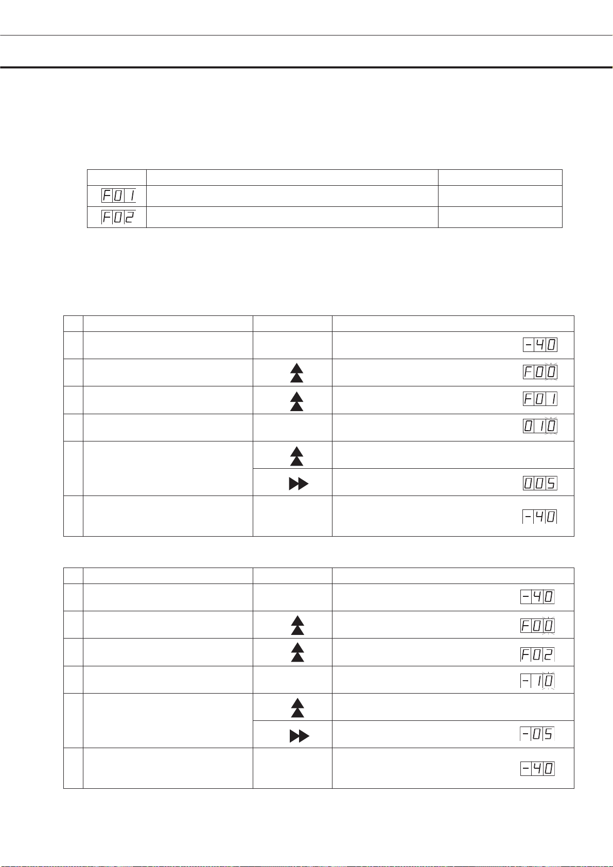
As an example, Table 3 shows the procedure to set the high temperature alarm so that the alarm can
activate when the chamber temperature is 5
Table 4 shows the procedure to set the low temperature alarm so that the alarm can activate when the
chamber temperature is 5
Table 3. Procedure for setting high temperature alarm
Description of operation Key operated Indication after operation
1 ----
Press numerical value shift key for
2
about 5 seconds.
Press numerical value shift key
3
and scroll the figure to 1.
o
C lower than the set temperature.
o
C of the set temperature at the factory.
o
C higher than the set temperature.
The current chamber temperature is
displayed.
The first digit is flashed.
The first digit is flashed.
o
C and +15oC, and -5oC and -15oC for
4 Press set key. SET The first digit is flashed.
Scroll the figure to 005 by using
5
digit shift key and numerical value
shift key
6 Press set key. SET
Table 4. Procedure for setting low temperature alarm
Description of operation Key operated Indication after operation
1 ----
Press numerical value shift key for
2
about 5 seconds.
Press numerical value shift key
3
and scroll the figure to 2.
4 Press set key. SET The first digit is flashed.
Scroll the figure to -05 by using
5
digit shift key and numerical value
shift key
6 Press set key. SET
• The temperature set mode returns to the temperature display mode automatically when 90 seconds has
passed without any key operation.
The first digit is flashed.
When pressed, the figure of settable
digit changes.
When pressed, the changeable digit
moves.
Alarm temperature is memorized and
the current chamber temperature is
displayed.
The current chamber temperature is
displayed.
The first digit is flashed.
When pressed, the figure of settable
digit changes.
When pressed, the changeable digit
moves.
Alarm temperature is memorized and
the current chamber temperature is
displayed.
15
- 43 -
Page 47

SETTING OF ALARM RESUME TIME
The buzzer and remote alarm are silenced by pressing buzzer stop key (BUZZER) on the control panel
during alarm condition. The buzzer and remote alarm will be activated again after certain suspension if
the alarm condition is continued. The suspension time can be set by following the procedure shown in
the Table 5 below.
The example in the table is based on the assumption that the desired duration is 20 minutes.
Note: The duration is set in 30 minutes at the factory.
Table 5. Setting procedure for alarm resuming time (change from 30 minutes to 20 minutes)
Description of operation Key operated Indication after operation
1 ----
2 Press digit shift key for 5 seconds. The first digit is flashed.
The current chamber temperature is
displayed.
Set the figure to F25 with the digit
shift key and numerical value shift
3
key.
4 Press set key. SET
Set the figure to 020 with the
5
numerical value shift key.
6 Press set key. SET
• The settable alarm resume time are 10, 20, 30, 40, 50, or 60 minutes. The buzzer and remote alarm
would not reset if the resume time is set in 000.
• The setting of alarm reset time cannot be changed during the defrosting.
• The buzzer and remote alarm during power failure or alarm testing cannot be silenced.
• The temperature set mode returns to the temperature display mode automatically when 90 seconds has
passed without any key operation.
When pressed, the figure of settable
The settable digit is shifted.
digit changes.
The current reset time is displayed.
The middle digit is flashed.
When pressed, the figure of settable
digit changes.
The setting is memorized and
the current chamber temperature is
displayed.
- 44 -
16
Page 48

REMOTE ALARM TERMINAL
WARNING
Always disconnect the power supply cord before connecting an alarm device to the remote alarm
terminal.
The remote alarm terminal is installed at the back of the unit. The alarm is outputted from this terminal.
Contact capacity is DC 30 V, 2 A.
Contact output:
between COM. and N.O. between COM. and N.C.
At normal Open Close
At abnormal Close Open
Note: The remote alarm is silenced by pressing the buzzer stop key (BUZZER) as the remote alarm is
operated in conjunction with the buzzer except for the power failure alarm and alarm test.
• It is the same condition with being abnormal at the time of the power failure.
17
- 45 -
Page 49

ALARMS & SAFETY FUNCTIONS
This unit has the alarms and safety functions shown in Table 6, and also self diagnostic functions.
Table 6 Alarms and safety functions
Alarm & Safety Situation Indication Buzzer Safety operation
High temperature
alarm
Low temperature
alarm
Power failure
alarm
Auto-return
Key lock When the key lock is ON. ----- -----
Thermal sensor
Abnormality
Battery switch
check
Temperature
control
sensor abnormality
Battery check
Fan motor check
If the chamber temperature is higher
than the temperature at which the
high temperature alarm is activated.
If the chamber temperature is lower
than the temperature at which the
low temperature alarm is activated.
In the case of power failure.
When power switch is turned OFF.
When the power to the unit is
disconnected.
When there is no key pressing in
each setting mode for 90 seconds.
If the thermal sensor is disconnected.
If the thermal sensor is short-circuited.
When battery switch is OFF at the time
of alarm test.
If the sensor is disconnected.
If the thermal sensor is short-circuited.
When about 3 years has passed with
power switch ON.
When about 6 years has passed with
power switch ON.
Alarm lamp is flashed.
Temperature indicator is
flashed.
Alarm lamp is flashed.
Temperature indicator is
flashed.
Alarm lamp is flashed. Intermittent tone Remote alarm.
Chamber temperature is
displayed.
Alarm lamp is flashed.
E01 and chamber temp.
are displayed alternately.
Alarm lamp is flashed.
E02 and chamber temp.
are displayed alternately.
Alarm lamp is flashed.
E09 is flashed.
Alarm lamp is flashed.
E11 and chamber temp.
are displayed alternately.
Alarm lamp is flashed.
E12 and chamber temp.
are displayed alternately.
_F01 and chamber temp.
are displayed alternately.
_F02 and chamber temp.
are displayed alternately.
Intermittent tone with
15 minutes delay.
Intermittent tone with
15 minutes delay.
Intermittent tone
Intermittent tone
Intermittent tone Remote alarm.
Intermittent tone
----- -----
----- -----
Remote alarm with 15
minutes delay.
Remote alarm with 15
minutes delay.
----- Finishing of each
Setting mode.
Change of setting is
disable.
Remote alarm.
Continuous running.
Remote alarm.
Continuous running.
Remote alarm.
Normal operation.
Note:
• The above power failure alarm is available when the battery switch is on and the battery is charged. If
the battery switch is off or the battery is discharged, only the remote alarm is activated.
• The power failure alarm can be kept about 12 hours with the battery charged fully. A two-day operation
of the freezer is needed to charge the battery full.
• The chamber temperature is displayed for 5 seconds if the buzzer stop key (BUZZER) key is depressed
during the power failure alarm. At the same time, the alarm stops.
• The remote alarm is silenced by pressing buzzer stop key (BUZZER) as the remote alarm is operated in
conjunction with the buzzer, except for the power failure alarm.
• After power failure, the operation is resumed with the condition before power failure since the
temperature setting and alarm temperature setting are memorized in a nonvolatile memory.
- 46 -
18
Page 50

ROUTINE MAINTENANCE
WARNING
Always disconnect the power supply to the unit prior to any repair or maintenance of the unit in
order to prevent electric shock or injury.
Ensure you do not inhale or consume medication or aerosols from around the unit at the time of
maintenance. These may be harmful to your health.
Cleaning of cabinet
• Clean the unit once a month. Regular cleaning keeps the unit looking new.
• Use a dry cloth to wipe off small amounts of dirt on the outside and inside of the unit and all accessories.
If the outside panels are dirty, clean them with a diluted neutral dishwashing detergent. (Undiluted
detergent can damage the plastic components. For the dilution, refer to the instruction of the detergent.)
After the cleaning with the diluted detergent, always wipe it off with a wet cloth. Then wipe off the cabinet
or accessories with a dry cloth.
• Never pour water onto or into the unit. Doing so can damage the electric insulation and cause failure.
• The compressor and other mechanical parts are completely sealed. This unit requires absolutely no
lubrication.
• Remove the frost or ice on the chamber wall and clean the condenser filter once a month.
Defrosting
This product is refrigerated by the direct cooling. When it uses for a long time, frost appears on the
chamber wall side. It cannot be cooled down when there is much amount of frost. The defroster is
mentioned in the following.
Use the scraper provided for removing the frost if the freezer operation must be continued. Pay attention
not to impact or damage the inner wall.
1. When defrosting, temporarily move all the contents of containers in the freezer to another
low-temperature freezer.
2. Place the empty defrost/storage container inside the freezer.
3. Press defrost key (DEF) for 5 seconds to stop the refrigerating operation. While the refrigerating
operation is stopped, the current chamber temperature and dF is displayed on the control panel
alternately.
4. After a several hours, check visually that all frost was removed completely.
5. Throw out the water that has accumulated in the defrost/storage containers, then wipe the inside of the
freezer.
6. Press defrost key (DEF) so that the refrigerating operation can be started.
7. Once the chamber temperature has dropped to the desired temperature, place the original contents
back in the freezer chamber.
Note:
After the defrosting, the refrigerating operation is never resumed automatically. Make sure to press
defrost key (DEF) to start the refrigerating operation after defrosting.
19
- 47 -
Page 51

REPLACEMENT OF BATTERY
x
Location of a nickel-metal-hydride battery
This unit is provided a nickel-metal-hydride battery for the power failure warning device. The battery is
located in the battery mounting plate inside the cover on the upper side. (Fig. 1)
The high voltage components are enclosed in the electrical box. The cover should be removed
by a qualified engineer or a service personnel only to prevent the electric shock.
Removal of nickel-metal-hydride battery
1. Turn off the power switch and disconnect the power supply plug.
2. Remove 6 screws fixing the top cover with a screw driver and remove the top cover. (Fig. 2)
3. Disconnect the battery connector and remove 2 screws fixing the battery mounting plate. (Fig. 3)
4. Take out the battery. (Fig. 4)
5. Follow the procedure for recycling or proper disposal.
Handling of battery
Cover the battery terminal with an insulating tape to avoid the short circuit. Then follow the procedure for
recycling or proper disposal.
Electrical bo
Battery㩷
Top cover
䂯
䂯
Fig. 1
䂯
䂯
Fig. 2
Battery connector
Battery
Battery㩷
mounting plate
Fig. 3 Fig. 4
- 48 -
20
Page 52

TROUBLE SHOOTING
If the unit malfunctions, check out the following before calling for service.
Malfunction Check/Remedy
The chamber is not cooled
at all
The cooling is poor
Noise
㩵 The circuit breaker of power source is active
㩵 The voltage is too low. (In this case, call an electrician.)
㩵 The power switch is not ON.
㩵 The large amount of articles (load) is stored in the chamber at
one time.
㩵 The freezer is in defrost condition.
㩵 The ambient temperature is too high.
㩵 The door is not closed firmly.
㩵 The large amount of frost is built on the chamber wall.
㩵 The air intake vent is blocked.
㩵 The set temperature is not inputted properly.
㩵 The freezer is in the direct sunlight.
㩵 There is any heating source near the freezer.
㩵 A rubber cap and insulation for the access port are not set
correctly.
㩵 You put too many unfrozen articles into the freezer compartment.
㩵 The freezer is not installed on the sturdy floor.
㩵 The freezer is not leveled with the leveling feet.
㩵 There is anything touching the frame.
㩵 The freezer is in the status immediately after start up.
The unit sometimes causes a noise when the chamber temperature
is high due to the large load. The noise gets less and less
accompanying with the cooling of the chamber.
Note:
If the malfunction is not eliminated after checking the above items, or the malfunction is not shown in the
above table, contact Sanyo sales representative or agent.
21
- 49 -
Page 53

DISPOSAL OF UNIT
WARNING
If the unit is to be stored unused in an unsupervised area for an extended period ensure that children do
not have access and doors cannot be closed completely.
The disposal of the unit should be accomplished by appropriate personnel. Always remove doors
to prevent accidents such as suffocation.
Recycle of battery
The unit contains a rechargeable battery. The battery is recyclable. At the end
of it’s useful life, check with you local solid officials option or proper disposal.
䋪Label indication is obliged to comply with Taiwanese battery regulation.
ᑜ㔚ᳰ㩷
⺧࿁ᡴ㩷
- 50 -
22
Page 54

DISPOSAL OF UNIT
(English)
FOR EU USERS
The symbol mark and recycling systems described below apply to EU countries and do not apply to
countries in other areas of the world.
Your SANYO product is designed and manufactured with high quality materials and components which
can be recycled and/or reused.
The symbol mark means that electrical and electronic equipment, batteries and accumulators, at their
end-of-life, should be disposed of separately from your household waste.
Note:
If a chemical symbol is printed beneath the symbol mark, this chemical symbol means that the battery or
accumulator contains a heavy metal at a certain concentration. This will be indicated as follows: Hg:
mercury, Cd: cadmium, Pb: lead
In the European Union there are separate collection systems for used electrical and electronic equipment,
batteries and accumulators.
Please, dispose of them correctly at your local community waste collection/recycling centre.
Please, help us to conserve the environment we live in!
(German)
Für EU-Staaten
Das Symbol und das erwähnte Wiederverwertungssystem gelten nur für die Länder der EU und nicht für
andere Länder oder Gebiete in der Welt.
Die Produkte von SANYO werden aus hochwertigen Materialien und Komponenten gefertigt, die sich
wieder verwenden lassen.
Das Symbol bedeutet, dass elektrische oder elektronische Geräte, Batterien und Akkus am Ende ihrer
Lebensdauer nicht im Haushaltmüll entsorgt werden dürfen.
Hinweis:
Ein chemisches Zeichen unter dem Symbol bedeutet, dass die Batterie bzw. der Akku Schwermetalle in
gewissen Konzentrationen enthält. Die Metalle werden wie folgt bezeichnet: Hg: Quecksilber, Cd:
Kadmium, Pb: Blei
In der Europäischen Union gibt es separate Sammelstellen für elektrische und elektronische Geräte,
Batterien und Akkus.
Entsorgen Sie solche Geräte bitte richtig in der kommunalen Sammelstelle bzw. im Recyclingzentrum.
Helfen Sie mit, die Umwelt in der wir leben, zu schützen.
23
- 51 -
Page 55

DISPOSAL OF UNIT
(French)
POUR LES UTILISATEURS DE UE
Le symbole et les systèmes de recyclage évoqués ci-dessous s'appliquent uniquement aux pays de UE.
Votre produit SANYO est conçu et fabriqué avec des composants et des matériaux de hautes qualités qui
peuvent être recyclés et/ou réutilisés.
Le symbole signifie que les équipements électriques et électroniques, les batteries et les accumulateurs
ne doivent pas être mis au rebut avec les déchets domestiques à l'issue de leur durée de vie.
Remarque:
Si un symbole chimique est imprimé sous le symbole, le symbole chimique indique que la batterie ou
l'accumulateur contient une certaine concentration de métaux lourds. Les métaux sont indiqués de la
manière suivante: Hg: mercure, Cd: cadmium, Pb: plomb.
Il existe différents systèmes de collecte pour les équipements électriques et électroniques, les batteries et
les accumulateurs usagés au sein de l'Union européenne.
Veuillez mettre les équipements au rebut de manière correcte, auprès de votre centre de recyclage/de
collecte des déchets local.
Aidez-nous à préserver l'environnement dans lequel nous vivons!
Les machines ou appareils électriques et électroniques contiennent fréquemment des matières qui, si
elles sont traitées ou éliminées de manière inappropriée, peuvent s’avérer potentiellement dangereuses
pour la santé humaine et pour l’environnement.
Cependant, ces matières sont nécessaires au bon fonctionnement de votre appareil ou de votre machine.
Pour cette raison, il vous est demandé de ne pas vous débarrasser de votre appareil ou machine usagé
avec vos ordures ménagères.
(Spanish)
PARA USUARIOS DE LA UNION EUROPEA
El símbolo y los sistemas de reciclado descriptos a continuación se aplican para países de la Unión
Europea y no se aplica para países en otras áreas del mundo.
Su producto SANYO fue diseñado y fabricado con materiales de alta calidad y componentes que pueden
ser reciclados y/o vueltos a usar.
El símbolo significa que los equipos eléctricos y electrónicos, baterías y acumuladores, al final de su vida
útil, debe ser desechados separadamente de sus residuos domiciliarios.
Nota:
Si hay un símbolo químico impreso debajo del símbolo, este símbolo químico significa que la batería o
acumulador contiene una cierta concentración de un metal pesado. Esto es indicado de la siguiente
manera: Hg: mercurio, Cd: cadmio, Pb: plomo
En la Unión Europea hay sistemas de recolección separados para equipos eléctricos y electrónicos,
baterías y acumuladores usados.
Por favor, disponga de ellos correctamente en el centro de recolección de residuos/reciclado de la
comunidad de su localidad.
Por favor, ayúdenos a proteger el medio ambiente en que vivimos!
- 52 -
24
Page 56

DISPOSAL OF UNIT
(Portuguese)
PARA UTILIZADORES DA UE
O símbolo e os sistemas de reciclagem descritos abaixo aplicam-se aos países da UE e não se aplicam
aos países noutras áreas do mundo.
O seu produto SANYO foi concebido e fabricado com materiais e componentes de elevada qualidade que
podem ser reciclados e/ou reutilizados.
O símbolo significa que o equipamento eléctrico e electrónico, baterias e acumuladores, em final de vida,
não devem ser deitados fora juntamente com o lixo doméstico.
Atenção:
Se estiver impresso um símbolo químico debaixo do símbolo de , este símbolo químico significa que a
bateria ou acumulador contém um metal pesado numa determinada concentração. Estará indicado da
seguinte forma: Hg: mercúrio, Cd: cádmio, Pb: chumbo
Na União Europeia existem sistemas de recolha separados para equipamento eléctrico e electrónico,
baterias e acumuladores.
Por favor, entregue-os no seu centro de reciclagem/recolha de lixo local.
Por favor, ajude-nos a conservar o ambiente!
(Italian)
PER UTENTI UE
Il simbolo e i sistemi di riciclaggio descritti di seguito si applicano esclusivamente ai paesi dell’UE.
Questo prodotto SANYO è stato progettato e realizzato con materiali e componenti di elevata qualità che
possono essere riciclati e/o riutilizzati.
Il simbolo di riciclaggio mostrato di seguito indica che i dispositivi elettrici ed elettronici, le batterie e gli
accumulatori, una volta esauriti, devono essere smaltiti separatamente rispetto ai rifiuti domestici.
Nota:
Se sotto il simbolo di riciclaggio appare un simbolo chimico, esso sta ad indicare che la batteria o
l’accumulatore contengono metalli pesanti a determinate concentrazioni. Questo viene specificato come
segue: Hg: mercurio, Cd: cadmio, Pb: piombo.
Nell’Unione europea esistono diversi sistemi per la raccolta dei rifiuti speciali quali i dispositivi elettrici ed
elettronici, le batterie e gli accumulatori.
Si raccomanda di provvedere allo smaltimento di tali rifiuti secondo quanto previsto dalle normative vigenti
in materia.
Aiutaci a conservare l’ambiente!
25
- 53 -
Page 57

DISPOSAL OF UNIT
(Dutch)
VOOR GEBRUIKERS IN DE EU
Het symbool en de recycleersystemen die hieronder beschreven worden, zijn van toepassing op de
landen in de EU en zijn niet van toepassing op landen in andere delen van de wereld.
Uw SANYO product is ontworpen en gemaakt met materialen en onderdelen van hoge kwaliteit, die
gerecycleerd en opnieuw gebruikt kunnen worden.
Het symbool betekent dat elektrische en elektronische apparatuur, batterijen en accu's aan het eind van
hun leven apart van uw huisafval weggegooid moeten worden.
Let op:
Indien een chemisch symbool afgedrukt staat onder het symbool, betekent dit chemisch symbool dat de
batterij of accu een zwaar metaal met een bepaalde concentratie bevat. Dit wordt als volgt aangegeven:
Hg: kwik, Cd: cadmium, Pb: lood
In de Europese Unie zijn afzonderlijke inzamelingssystemen voor gebruikte elektrische en elektronische
apparatuur, batterijen en accu's.
Wilt u deze op de juiste manier weggooien bij uw plaatselijk afvalinzameling-/recyclingcentrum in uw
buurt?
Help ons het milieu waarin wij leven in stand te houden!
(Swedish)
FÖR ANVÄNDARE INOM EU
Den symbolmärkning och de återvinningssystem som beskrivs här nedan gäller länder inom EU och gäller
inte länder i någon annan del av världen.
Din SANYO-produkt har konstruerats och tillverkats med delar och material av hög kvalitet, som kan
återvinnas och/eller återanvändas.
Symbolmärkningen innebär att elektrisk och elektronisk utrustning, batterier och ackumulatorer, vid slutet
av deras livslängd, inte får slängas som hushållsavfall utan skall slängas separat.
Observera:
Om en kemisk symbol finns tryckt under denna symbolmärkning, betyder denna kemiska symbol att
batteriet eller ackumulatorn innehåller en tungmetall med en viss koncentration. Detta indikeras på
följande sätt: Hg: kvicksilver, Cd: kadmium, Pb: bly
I den Europeiska Unionen finns det separata uppsamlingssystem för använd elektrisk och elektronisk
utrustning, batterier och ackumulatorer.
Gör dig av med sådana saker på rätt sätt på den speciella lokala platsen för återsamling/återanvändning.
Hjälp oss att bevara den miljö vi lever i!
- 54 -
26
Page 58

TEMPERATURE RECORDER (OPTION)
WARNING
Always disconnect the power supply to the unit prior to attachment of a temperature recorder in
order to prevent electric shock or injury.
An automatic temperature recorders is available for the freezer as the optional component. The type of
the temperature recorder is MTR-G85 and MTR-4015LH. For the attachment, the mounting kit is
necessary. Following shows the combination of recorder with the mounting kit. Contact Sanyo sales
representative or agent for the attachment of an automatic temperature recorder. :
Temperature recorder Mounting kit
MTR-4015LH
MTR-G85 (circular chart type)
Setting of MTR-4015LH
Pull the knob on the upper part of the temperature recorder
forward to change the recording chart or battery.
MPR-S30
MPR-S7
Setting of recording chart
1. The information on the temperature recording chart is
shown in Fig. 1.
2. Pull the cartridge up after opening the top lid. The lid
can be opened by turning the knob counterclockwise.
See Fig. 2.
3. As shown in Fig. 3, insert the recording chart with the
“begin” tab placed in the cartridge. Check that the printed
side is facing out.
4. Place the recording chart beneath the arm and between
the plate spring and guide plate in the direction of the
arrow.
Note:
Ŷ Do not scratch or put pressure on the recording chart.
Ŷ Do no bend the recording chart.
Ŷ Do not reverse the recording chart manually.
Fig. 1
Fig. 2
Fig. 3
The used paper left in the used recording chart
compartment can cause a malfunction. Be sure to
remove it. See Fig. 4.
27
- 55 -
Fig. 4
Page 59

TEMPERATURE RECORDER (OPTION)
5. Place the recording chart between the guide and the
guide plate. Slide the recording chart along the guide plate
so that the recording chart will not be forced out of the
date/hour slot. See Fig. 5.
6. After ascertaining that the holes on the side of the chart
are locked into the teeth of the sprocket, turn the gear and
send the chart into the used chart compartment.
Setting of time
1. Turn the gear on the date/hour slot to the desired time.
2. After properly folding the recording chart in the used or
unused chart compartment, replace the cartridge.
Removing of the used recording chart
After recording, take out the cartridge and remove the
recording chart from the recording chart outlet. If not all of
the recording chart has been fed into the used recording
chart compartment, send all the recording chart in the
compartment first turning the gear.
Battery replacement
To replace the battery, turn the knob counterclockwise to open the lid. Place the battery in the battery
case according to the plus-minus indications on the bottom of the battery case. See Fig. 6. At the time
of the first use the battery.
Note :
This temperature recorder is designed for the manganese dry cell and the alkaline dry cell.
Do not use a rechargeable battery because the initial voltage of such battery is low. The rechargeable
battery may cause the malfunction of temperature recorder or shorten the battery life significantly.
Fig. 5
Fig. 6
Start-up
1. The quartz motor is started by placing a “R14” or size “C” dry cell battery in the battery case.
2. Check the operation of the recorder using the quartz motor rotation check gear.
3. Replace the battery once a year.
Stopping
The temperature recorder is stopped by taking the battery out of the battery case.
- 56 -
28
Page 60

TEMPERATURE RECORDER (OPTION)
Installation of MTR-4015LH
The temperature recorder is installed on the left lower front
of the freezer.
1. Remove the screw on the cover for the temperature
recorder space on the lower front of the freezer. Open the
cover and push the shaft on the both sides outward to
remove the cover. Fig. 7
2. Remove the wire grille on the back bottom of the freezer.
See Fig.9
3. Set the automatic temperature recorder (MTR-4015LH)
to the recorder fixture (MPR-S30:option) referring to a
manual enclosed with the recorder fixture. (Fig.8)
4. Install the temperature recorder in the temperature
recorder space.
5. Route the capillary tube of the temperature recorder to
the back of the freezer through the unit compartment.
6. Remove 2 rubber caps (outside and inside) on the
access port on the back of the freezer and also remove the
insulation in the port.
7. Pass the temperature recorder sensor into the chamber
through the access port. Fig. 10
8. After covering the temperature recorder sensor with the
cover provided, fix the recorder sensor under the 3rd shelf
by using 2 enclosed binders. See Fig. 11.
9. Make a small cut on the rubber caps for capillary to pass.
10. Replace the insulation into the access port and cover
the port completely with the rubber caps.
11. Replace the wire grille on the back bottom of the
freezer.
12. Operate the freezer until the chamber temperature gets
to the set temperature. Check the recorded temperature
and chamber temperature displayed on the control panel.
Adjust the zero adjustment volume on the temperature
recorder so that the recorded temperature can corresponds
with the displayed temperature if they are not compliance
each other
Recorder
fixture
Shaft
Fig. 7
Fig.8
Fig. 9
Access port
Fig. 10
29
Temperature recorder
sensor
Fig. 11
- 57 -
Page 61

TEMPERATURE RECORDER (OPTION)
Installation of MTR-G85
The temperature recorder is installed on the left lower
front of the freezer.
1. Attach the temperature recorder to the mounting kit
(MPR-S7) by following the procedure shown in the
manual enclosed with the mounting kit.
2. Remove the screw on the cover for the temperature
recorder space on the lower front of the freezer.
Open the cover and push the shaft on the both sides
outward to remove the cover. Fig. 12
3. Install the temperature recorder in the temperature
recorder space.
4. Join the wire in the unit compartment with the
temperature recorder wire by each wire connector.
See Fig. 13
5. Remove the wire grille on the back bottom of the
freezer. See Fig.14
6. Route the capillary tube of the temperature recorder
to the back of the freezer through the unit compartment
7. Remove 2 rubber caps (outside and inside) on the
access port on the back of the freezer and also remove
the insulation in the port.
8. Pass the temperature recorder sensor into the
chamber through the access port. Fig. 15
9. After covering the temperature recorder sensor with
the cover provided, fix the temperature recorder sensor
under the 3rd shelf by using 2 enclosed binders. See
Fig. 16.
10. Make a small cut on the rubber caps for capillary to
pass.
11. Replace the insulation into the access port and
cover the port completely with the rubber caps.
12. Replace the wire grille on the back bottom of the
freezer.
13. Operate the freezer until the chamber temperature
gets to the set temperature. Check the recorded
temperature and chamber temperature displayed on
the control panel. Adjust the zero adjustment volume
on the temperature recorder so that the recorded
temperature can corresponds with the displayed
temperature if they are not compliance each other
Shaft
Fig. 12
Fig. 13
Fig.
Access port
Fig. 15
- 58 -
Temperature
recorder sensor
Fig. 16
30
Page 62

SPECIFICATIONS
Name Biomedical Freezer
Model MDF-U5412
External dimensions W804 x D772 x H1802 (mm)
Internal dimensions W658 x D607 x H1272 (mm)
Effective capacity 482 L
Exterior Painted steel
Interior Styrol resin
Insulation Rigid polyurethane foamed-in place
Outer door Painted steel
Lock 1
Caster 4
Leveling leg 2
Evaporator Tube on sheet type (also used as a shelf)
Access port Diameter 30 mm, 2 on back side
Condenser Wire and tube type
Compressor Hermetic rotary type, 400 W
Refrigerant R-404A
Temperature controller Microcomputer control system
Temperature display Digital display (between -50 and +50
Temperature sensor Thermistor sensor
Temperature alarm Flash of digital indicator and alarm lamp, Buzzer, (Remote alarm)
Accessories
Weight 134 kg
Battery
Optional component
NoteDesign or specifications will be subject to change without notice.
• The battery for power failure alarm is an article for consumption. It is recommended that the battery will
be replaced about every 3 years. Contact Sanyo sales representative or agent at the time of replacement
of the battery for recycling.
• Fan motors are expendable supplies. Exchange it for about every 6 years. Contact Sanyo sales
representative or agent at the time of replacement of the fan motor.
6 small baskets for upper chamber; W290 x D536 x H136 (mm)
4 large baskets for lower chamber; W290 x D536 x H238 (mm)
Mounting kit for temperature recorder (MPR-S30, MPR-S7)
o
C)
1 set of key, 1 scraper
For power failure alarm, Nickel-metal-hydride battery,
DC 6 V, 1100 mAh, Automatic charge (5HR-AAC)
Temperature recorder (MTR-4015LH, MTR-G85)
Interface board (MTR-480, MTR-L03)
PERFORMANCE
Cooling performance -40oC (ambient temperature; 30oC, no load)
o
Temperature control range -20
Power source
Rated power consumption 240 W 285 W 255 W 290 W
Noise level 42 dB [A] (background noise; 20 dB)
Maximum pressure 1.80 MPa
Note The unit with CE mark complies with EC directives.
220 V
50 Hz
220 V
60 Hz
- 59 -
31
C to -40oC
230 V
50 Hz
240 V
50 Hz
Page 63

CAUTION
Please fill in this form before servicing.
Hand over this form to the service engineer to keep for his and your safety.
Safety check sheet
1. Freezer contents :
Risk of infection:
Risk of toxicity:
Risk from radioactive sources:
(List all potentially hazardous materials that have been stored in this unit.)
Notes :
2.
Contamination of the unit
Unit interior
No contamination
Decontaminated
Contaminated
Others:
غYes غNo
غYes غNo
غYes غNo
غYes غNo
غYes غNo
غYes غNo
غYes غNo
غYes غNo
3. Instructions for safe repair/maintenance of the unit
a) The unit is safe to work on
b) There is some danger (see below)
Procedure to be adhered to in order to reduce safety risk indicated in b) below.
Date :
Signature :
Address, Division :
Telephone :
Product name: Model: Serial number: Date of installation:
Biomedical Freezer MDF-U5412
㩷
Please decontaminate the unit yourself before calling the service engineer.
غYes غNo
غYes غNo
- 60 -
32
Page 64

SANYO Electric Co., Ltd
Printed in Japan
 Loading...