

Page 1
RoHS
This product does not contain any hazardous substances prohibited by the RoHS Directive.
(You will find ‘RSF’ mark near the rating plate on the RoHS compliant product.)
WARNING
* You are requested to use RoHS compliant parts for maintenance or repair.
* You are requested to use lead-free solder.
SM9910073
SANYO Electric Co., Ltd.
Biomedical Business Unit
Service Manual
Ultra-Low Temperature Freezer
MDF-U53V
MDF-U53VC
FILE No.
Page 2
Effective models
Following units are effective in this manual.
Model name Product code Voltage and Frequency
MDF-U53V 823 190 51 220V 50Hz
823 190 52 220V 60Hz
823 190 53 220V 60Hz
823 190 54 230/240V 50Hz
823 190 55 220V 50Hz
MDF-U53VC 823 190 80 220V 60Hz
Page 3

Contents
㩷㩷㩷㩷㩷㩷㩷㩷㩷㩷㩷㩷㩷㩷㩷㩷㩷㩷㩷㩷㩷㩷㩷㩷㩷㩷㩷㩷㩷㩷㩷㩷㩷㩷㩷㩷㩷㩷㩷㩷㩷㩷㩷㩷㩷㩷㩷㩷㩷㩷㩷㩷㩷
Page
Comparison MDF-U53V with MDF-U52V --------------------------------------- 1
Specifications --------------------------------------------- 2
* Structural specifications
* Control specifications
* Performance specifications
Dimensions ---------------------------------------------- 5
Refrigeration circuit
---------------------------------------------------
6
Refrigeration circuit welding points ---------------------------------------------- 7
Cooling unit parts ---------------------------------------------- 8
Components on PCB ---------------------------------------------- 9
Electrical parts ---------------------------------------------- 10
Specifications of sensor ---------------------------------------------- 11
Connections on PCB ---------------------------------------------- 12
Wiring diagram ---------------------------------------------- 13
Circuit diagram ---------------------------------------------- 15
Control specifications
---------------------------------------------------
16
Parts layout
---------------------------------------------------
25
Test data ---------------------------------------------- 27
* Pull-down data
* Pull-up data
* H/L EVA out data
* Unit pressure data
* Power consumption data
* Temperature uniformity
* Sample load test
Instruction Manual ---------------------------------------------- 32
Page 4

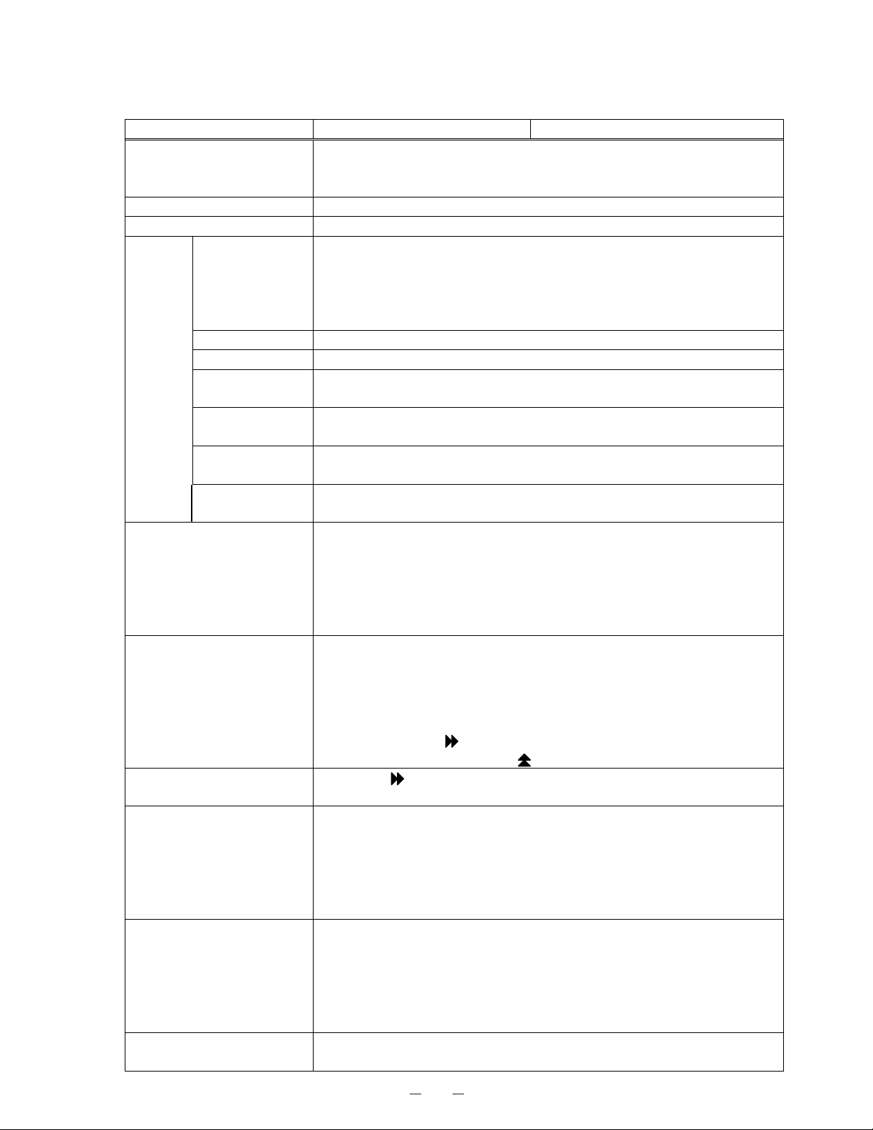
1
Comparison MDF-U53V with MDF-U52V
Item MDF-U52V MDF-U53V Remarks
Compressor Sanyo Toshiba career Toshiba compressor has
been cooperated
development.
H stage side 1100W 1100W
L stage side 1100W 1100W
Filter alarm FILTER lamp is lit FILTER lamp is lit and buzzer
sounds intermittently
2.8yrs, battery accumulating
time
䋨BATTERY lamp is lit䋩
2.8yrs, battery accumulating
time
䋨BATTERY lamp is lit䋩
Input code ‘409’ in F06 to
turn BATTERY lamp off.
You can see accumulation
time in F03.
Notification of
parts change
Fan motor accumulation time,
none
5.6yrs, fan motor accumulating
time
䋨BATTERY lamp is blinking䋩
Input code ‘419’ in F06 to
stop BATTERY lamp
blinking.
You can see accumulation
time in F32.
Overload relay Overload relay
Compressor
protection
䊶H stage side compressor is
ceased when it detects 70C
higher than filter sensor
temperature.
䊶E10 and PV are displayed
alternately.
䋨Buzzer sounds and remote
alarm terminal turns over䋩
䊶 H stage side compressor is
ceased when it detects 60C
higher than filter sensor
temperature.
䊶 E10 and PV are displayed
alternately.
䋨 Buzzer sounds and remote
alarm terminal turns over䋩
When it detects 10C lower
than AT sensor
temperature, H stage side
compressor turns on.
Status 3 Adding test value, SV and AT
makes the compared value.
Compared value = 95䋦䋨fixed䋩
Page 5
2
㩷 Specifications 㩷
ŶStructural specifications
Item MDF-U53V MDF-U53VC
Name Ultra-low Temperature Freezer
External dimensions W770 × D875 × H1990 (mm)
Internal dimensions W630 × D600 × H1400 (mm)
Effective capacity 519 L
Outer door 1door, painted steel
Inner door 2doors, ABS resin panel with stainless frame
Insulation Vacuum insulation panel + rigid polyurethane foamed-in place
Exterior Painted steel
Interior Painted steel
Shelf
3shelves, stainless steel
Inner dimensions; W608 x D533 (mm) Load; 50kg/shelf
Outer door latch 1pc
Outer door lock 1pc
Caster 4pcs (leveling leg:2pcs)
Monitoring hole 3places inner diameter; ij17mm
Refrigeration circuit Secondary cooling system
Compressor High stage side; Hermetic type, Output; 1100W
Low stage side; Hermetic type, Output; 1100W
Evaporator High stage side; Cascade condenser
Low stage side; Tube on sheet (Sharing with interior)
Condenser High stage side; Fin and Tube type
Low stage side; Cascade condenser
Refrigerant High stage side; R-407D (HFC refrigerant)
Low stage side; R-508 (HFC refrigerant)
Refrigerant oil Ze-NIUS32SA
Power supply Local voltage
Weight 305 Kg 310 Kg
Accessories 1 set of key, 1 scraper
Optional component Automatic temperature recorder(MTR-G85)
Back-up system (CVK-UB2, CVK-UB2(I)); LCO2
Inventory rack (IR-220, IR-224U)
Independent inner door (MDF-5ID)
Page 6
3
ŶControl specifications
Item MDF-U53V MDF-U53VC
Temp. controller Microcomputer control system
Temperature setting range: -50°C∼-90°C
Non-volatile memory
Thermal sensor Pt.1000ȍ
Temperature display Digital display
Temperature
+5°C~+20°C for High temperature alarm (Initial; +10°C)
-5°C~-20°C for Low temperature alarm (Initial; -10°C)
ALARM lamp blinks and buzzer sounds intermittently with 15min. delay
Remote alarm contact; Normal Open, Normal Close
Allowable contact capacity; 30VDC, 2A
Door DOOR lamp is list with 2min. delay
Filter check FILTER lamp is lit and buzzer sounds intermittently
Power failure
ALARM lamp blinks, buzzer sounds intermittently and remote alarm is
output.
Remote alarm
Remote alarm terminal 3P; DC30V, 2A
NC-COM, NO-COM
Alarm
Battery check
When approx. 2.8yrs has passed with power switch is on, BATTERY lamp
is lit.
Fan motor check When approx. 5.5yrs has passed with power switch ON, BATTERY lamp
is flashed.
Freezer status monitor
・ Abnormal low voltage (When the power source voltage is 15% less
than the rated voltage)
・ Abnormal ambient temperature (When the ambient temperature is
over 35°C or lower than 0°C)
・ Overloaded run (When the running rate of compressor (L) is over
90%)
Control panel
Lamps: ALARM, BATTERY, STATUS, DOOR, FILTER
Buzzer key: BUZZER
Alarm test key: ALARM TEST
Status key: STATUS
Set key: SET
Digit shift key:
Numerical value shift key:
Key lock function
Press key for 5 seconds to display;
L0: Key lock is off L1: Key lock is on
Sensor abnormality
When any failure is occurred in sensor among temp. sensor, filter sensor,
cascade sensor and AT sensor;
zError code is displayed
zALARM lamp blinks
zRemote alarm is on
zBuzzer sounds intermittently
Compressor protection
When the cascade sensor temperature is lower than -34°C, Compressor
L is turned on.
When the cascade sensor temperature is higher than -12°C, Compressor
L is turned off.
When the overload relay and/or filter sensor is higher than +60°C,
Compressor H is turned off.
Compressor delay time
You can change the delay time both of Compressor L & H as;
2∼15min.
Page 7
4
㩷
ŶPerformance specifications
Cooling performance
-86°C at the center of the chamber (AT30°C, no load)
Temperature control range
-50°C~-86°C(AT30°C, no load)
Power source 220V, 50Hz 220V, 60Hz 230V, 50Hz 240V, 50Hz
Rated power consumption 1020W 1180W 1070W 1150W
Noise level 49 dB {A} (background noise 20dB)
Maximum pressure 2600 kPa
Usable conditions
AT; +5°C~+30°C Humidity: Less than 80%RH
* Design or specifications will be subject to change without notice.
Page 8
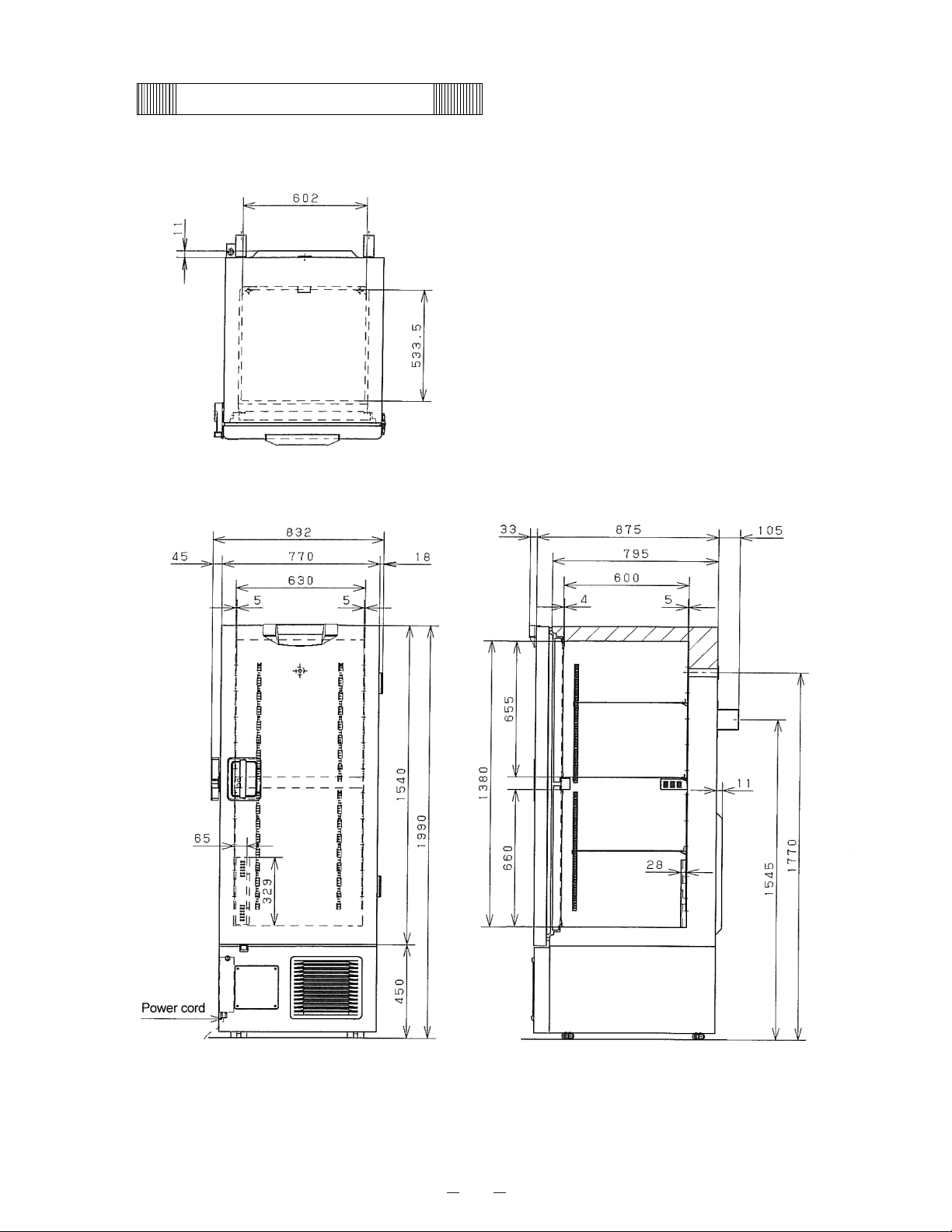
5
Dimensions
Page 9
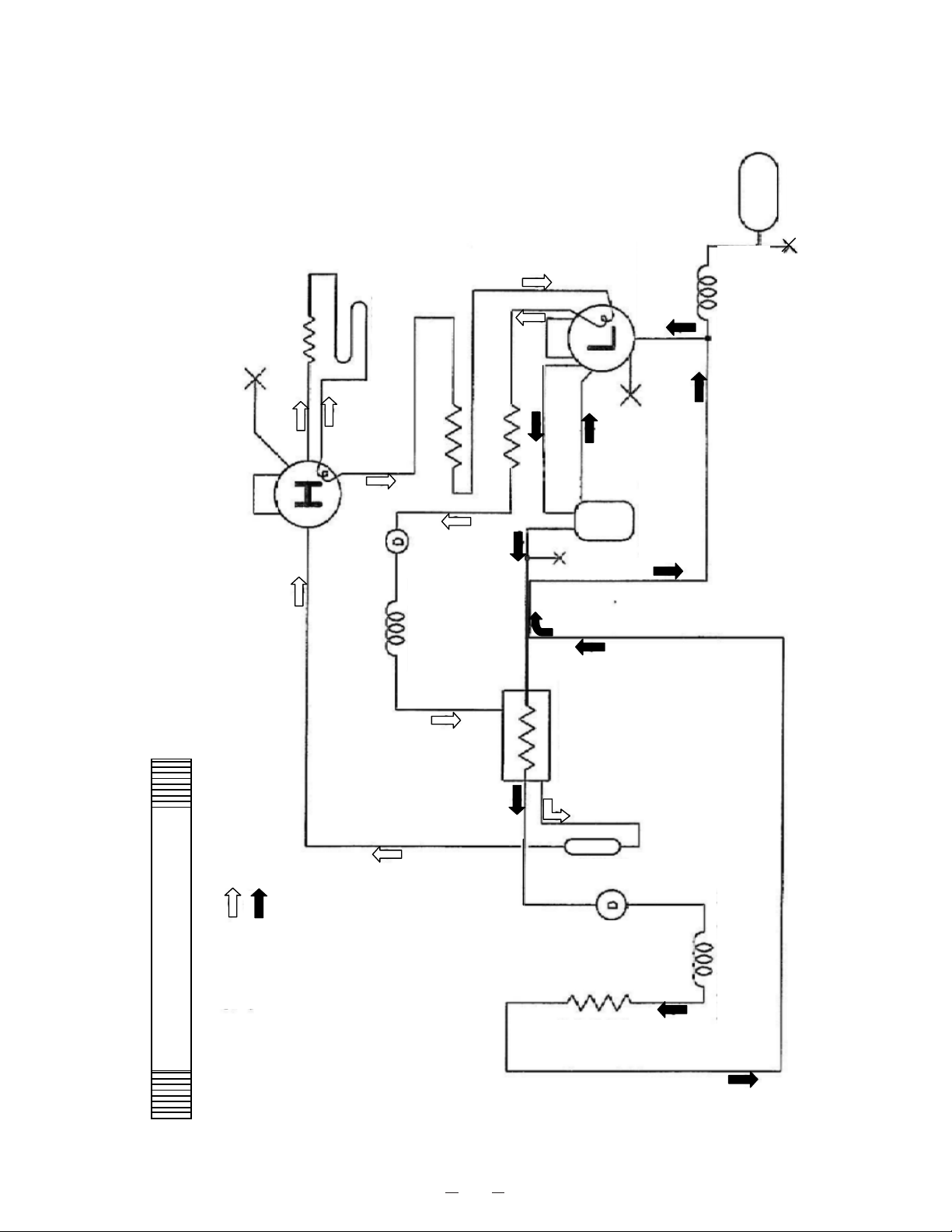
6
Refrigeration circuit
H side
L side
Compressor H
Pre-condenser
Frame pipe
Pre-condenser
Condenser
Dryer H
Capillary tube H
Compressor L
Oil separator
Capillary tube
EX
EX tank
Heat exchanger
Cascade condenser
Capillary tube L
Header
Dryer L
Evaporator
Page 10
7
Refrigeration circuit welding points
< Unit Base Ass’y >
䌈䌄䌉㩷
䌈䌄㪦㩷
䌈䌄䌁㩷
䌈䌄䌂㩷
䌌䌓䋲
䌈䌃䌉㩷
䌈䌍䌏㩷
䌈䌍䌉㩷
䌈䌃䌏
䌈䌅䌏㩷
䌆䌉㩷
䌆䌏㩷
䌈䌏䌁
䌈䌏䌏䌈䌏䌉㩷
䌈䌏䌂
䌌䌄䌄
䌈䌏䌑
䌈䌏䌐
䌌䌏䌁
䌌䌏䌏㩷
䌌䌏䌉㩷
䌌䌏䌂
䌌䌄䌂
䌈䌏䌓㩷
䌈䌏䌒
䌈䌓䌂
䌈䌓䌁
䌌䌒䌂
䌌䌒䌁
䌈䌃䌃
䌈䌃䌂
䌈䌃䌁
䌏䌒㩷
䌏䌏㩷
䌏䌉㩷
䌌䌋䌉㩷
䌌䌋䌏
䌔䋳㩷
䌔䋲㩷
䌔䋱㩷
䌌䌓䋱
䌌䌓䌂
䌌䌓䌁
䌌䌓䋳
䌌䌂䌃㩷
䌌䌂䌂
䌌䌂䌁㩷
䌌䌃䌃
䌏䌒䋳
䌏䌒䋲
䌏䌒䋱
䌌䌂䌚㩷
䌌䌂䌙㩷
䌅䌘䌏
㪚㪉㩷
㪚㪊㩷
㪚㪋㩷
㪚㪌㩷
㪚㪍㩷
㪚㪎㩷
㪚㪏㩷
㪚㪐㩷
㪚㪈㪇㩷
㪚㪈㪈㩷
㪚㪈㪉㩷
㪚㪈㪊㩷
䌅䌘䌉㩷
䌅㩷
D
䌆㩷
Compressor L
Compressor H
Ex. tank L
Condenser
Dryer H
Oil separator
Page 11
8
Cooling unit parts
<MDF-U53V/U53VC>
Specifications
Item
H side L side
Compressor 220V, 60Hz 220V, 50Hz 230/240V, 50Hz
Code 7FB-0-M101-001-06 7FB-0-M101-001-04 7FB-0-M101-001-05
Type KS370J1NS-7A KS370J1NS-4A KS370J1NS-4A1
Refrigerant oil
Ze-NIUS32SA
Charged q’ty: 850cc
Ze-NIUS32SA
Charged q’ty: 850cc
Cooling system
Forced air cooling(partially)
Oil cooler
Forced air cooling(partially)
Oil cooler
Condenser
Type Fin and tube Cascade condenser
Condenser 12 columns x 4 lines P6.35mm
Fin 88pcs.
Coil pipeφ6.35mm
Pre-condenser W 250mm
ʊ
Frame pipe
φ4.76mm
ʊ
Evaporator
Type
Cascade condenser
Shell and tubeφ80mm
Tube on sheet
φ9.52mm
Capillary tube Ex. capillary
Resistance
PSI・kg/cm
2
94 PSI/G 98 PSI/G 34 PSI/G
Length 1800mm 1200mm 500mm
Outer diameter
φ2.0mm φ2.0mm φ2.4mm
Inner diameter
φ1.0mm (φ0.9mm) φ1.2mm
Refrigerant R-407D Charged q’ty: 564g R-508 Charged q’ty: 260g
Oil additive
n-Pentane
Charged-q’ty: 60cc (36g)
n-Pentane
Charged q’ty: 58cc (36.8g)
Dryer 4A-XH-9 Charged q’ty: 18g 4A-XH-6 Charged q’ty: 58g
Condensing fan
φ230 mm、4 blades
Material: ABS
Condensing fan
motor Type SE4-E11L3P (high stage side)
Oil separator
ʊ
SPK-0S02S2
(810-4-2008)
<Compressor terminals layout>
C
S
R
Page 12
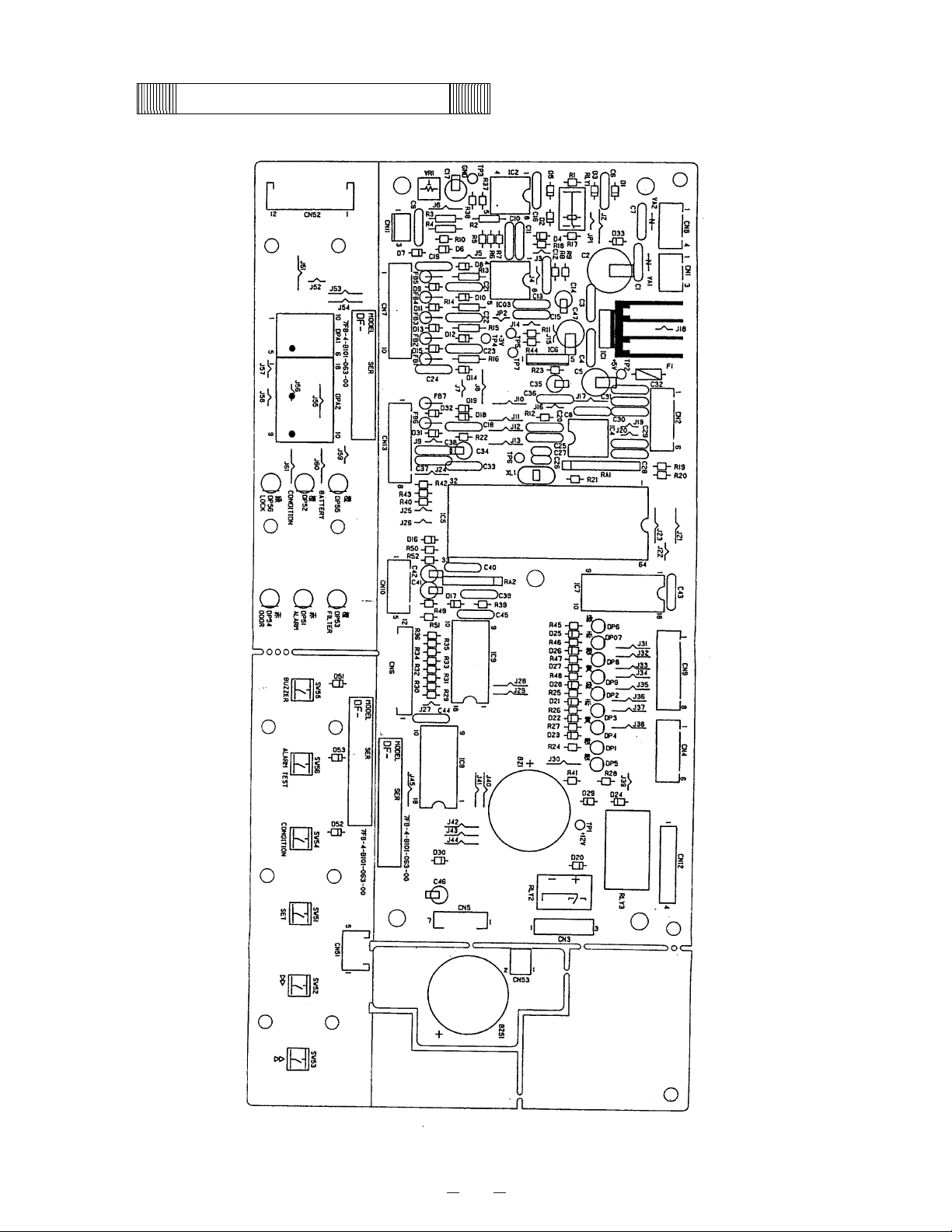
9
Components on PCB
Page 13
10
Compressor (H),(L)
Type KS370J1NS-7
A
KS370J1NS-4
A
KS370J1NS-4AI
Code 7FB-0-M101-001-06 7FB-0-M101-001-04 7FB-0-M101-001-05
Rated voltage (50/60Hz) 220V, 60Hz 220/230V, 50Hz 230/240V, 50Hz
Winding resistance C-S(Aux) 1.64㱅 2.53㱅 2.53㱅
C-R(Main) 3.35㱅 4.8㱅 4.8㱅
Starting relay(H), (L)
Type AMVL-300
A
AMVL-300
A
AMVL-300
A
Pick up voltage 215~247VAC(60Hz) 185~217VAC(50Hz) 185~217VAC(50Hz)
Drop out voltage 69~132VAC(60Hz) 60~120VAC(50Hz) 60~120VAC(50Hz)
Parts code 626 100 1503 626 100 1503 626 100 1503
Overload relay (H), (L)
Type MRA999549201 MRA999539201 MRA999539201
Action to the temp. (no current) ON:69±11㷄 OFF:135±5㷄 ON:69±11㷄 OFF:135±5㷄 ON:69±11㷄 OFF:135±5㷄
Action to the current (AT25℃) 29.5A 22.5A 22.5A
Operation time 6~16sec. 6~16sec. 6~16sec.
Parts code 624 226 3173 624 226 3166 624 226 3166
Starting capacitor(H),(L) Rating 250VAC, 10MF 250VAC, 10MF 250VAC, 10MF
Running capacitor (H),(L
)
Rating 400VAC, 25MF 400VAC, 25MF 400VAC, 25MF
Condensing fan moto
r
Type SE4-E11L5P SE4-E11L5P SE4-E11L5P
Rating 220-240VAC 220-240VAC 220-240VAC
Parts code 624 224 0167 624 224 0167 624 224 0167
Cap.tube heater
Rating 230V, 12W 230V, 12W 230V, 12W
Parts code 624 200 0280 624 200 0280 624 200 0280
H Comp. rela
y
Type G4F-11123T G4F-11123T G4F-11123T
Contact capacit
y
20A, 250VAC 20A, 250VAC 20A, 250VAC
Coil 12VDC 12VDC 12VDC
Parts code 624 173 2397 624 173 2397 624 173 2397
Heater rela
y
Type G2R-1A-T G2R-1A-T G2R-1A-T
Contact capacit
y
10A, 250VAC 10A, 250VAC 10A, 250VAC
Coil 12VDC 12VDC 12VDC
Parts code 624 188 9299 624 188 9299 624 188 9299
Temp. control rela
y
Type G4F-11123T G4F-11123T G4F-11123T
Contact capacit
y
20A, 250VAC 20A, 250VAC 20A, 250VAC
Coil 12VDC 12VDC 12VDC
Parts code 624 173 2397 624 173 2397 624 173 2397
Switching power suppl
y
Type LDA10F-12 LDA10F-12 LDA10F-12
Rated output 12VDC, 0.9
A
12VDC, 0.9
A
12VDC, 0.9
A
Parts code 624 226 2053 624 226 2053 624 226 2053
Temperature sensor
Type SS-12-T SS-12-T SS-12-T
Rating 1000㱅 1000㱅 1000㱅
AT senso
r
Type 502AT 502AT 502AT
Rating 5K㱅, 25㷄 5K㱅, 25㷄 5K㱅, 25㷄
Filter sensor
Type 502AT 502AT 502AT
Rating 5K㱅, 25㷄 5K㱅, 25㷄 5K㱅, 25㷄
Cascade senso
r
Type 502AT 502AT 502AT
Rating 5K㱅, 25㷄 5K㱅, 25㷄 5K㱅, 25㷄
Door switch
Type SDKNA20700 SDKNA20700 SDKNA20700
Rating 5V, 5MA 5V, 5MA 5V, 5MA
Noise filte
r
Type ZAC2220-11 ZAC2220-11 ZAC2220-11
Rating 250VAC, 20
A
250VAC, 20
A
250VAC, 20
A
Power cord
Type GTVD-2,3 GTVD-2,3 GTVD-2,3
Battery switch
Type SLE6A2-5 SLE6A2-5 SLE6A2-5
Rating 250VAC, 4
A
250VAC, 4
A
250VAC, 4
A
Type 5HR-AAC 5HR-AAC 5HR-AAC
Rating 6V, 1100mAH 6V, 1100mAH 6V, 1100mAH
Parts code 624 209 9284 624 209 9284 624 209 9284
Handle heate
r
Rating 9VAC, 0.83W 9VAC, 0.83W 9VAC, 0.83W
Transformer
Type S41-RN97P
V
S41-RN97P
V
S41-RN97P
V
Primar
y
115V 115V 115V
Secondar
y
230V 230V 230V
Parts code 624 226 7645 624 226 7645 624 226 7645
Breaker switch
Type BAM215131 BAM215131 BAM215131
Rating 250V, 15A 250V, 15A 250V, 15A
Boost rela
y
Type G7L-1A-TUB
(MDF-U53VC only)
Rating 30A, 220V, DC24V
Power rela
y
Type DS1E-M-DC12V
(MDF-U53VC only)
Rating 12V, 0.4A, 125V
Breaker switch
Type IR11A2E201
R
(MDF-U53VC only)
Rating 250VAC, 20
A
Power transformer
Type ATR-HJ61TC-1
(MDF-U53VC only)
Rating 200, 225, 240V
Power transformer
Type ATR-D35003
(MDF-U53VC only)
Rating P;208V, S;230V
* For the compressor specified for China;
Type: KS370J1NS-4A (CCC authorized)
230/240VAC, 50Hz
220VAC, 50Hz
Battery
220VAC, 60Hz
MDF-U53V/U53VC
Electrical Parts
Page 14
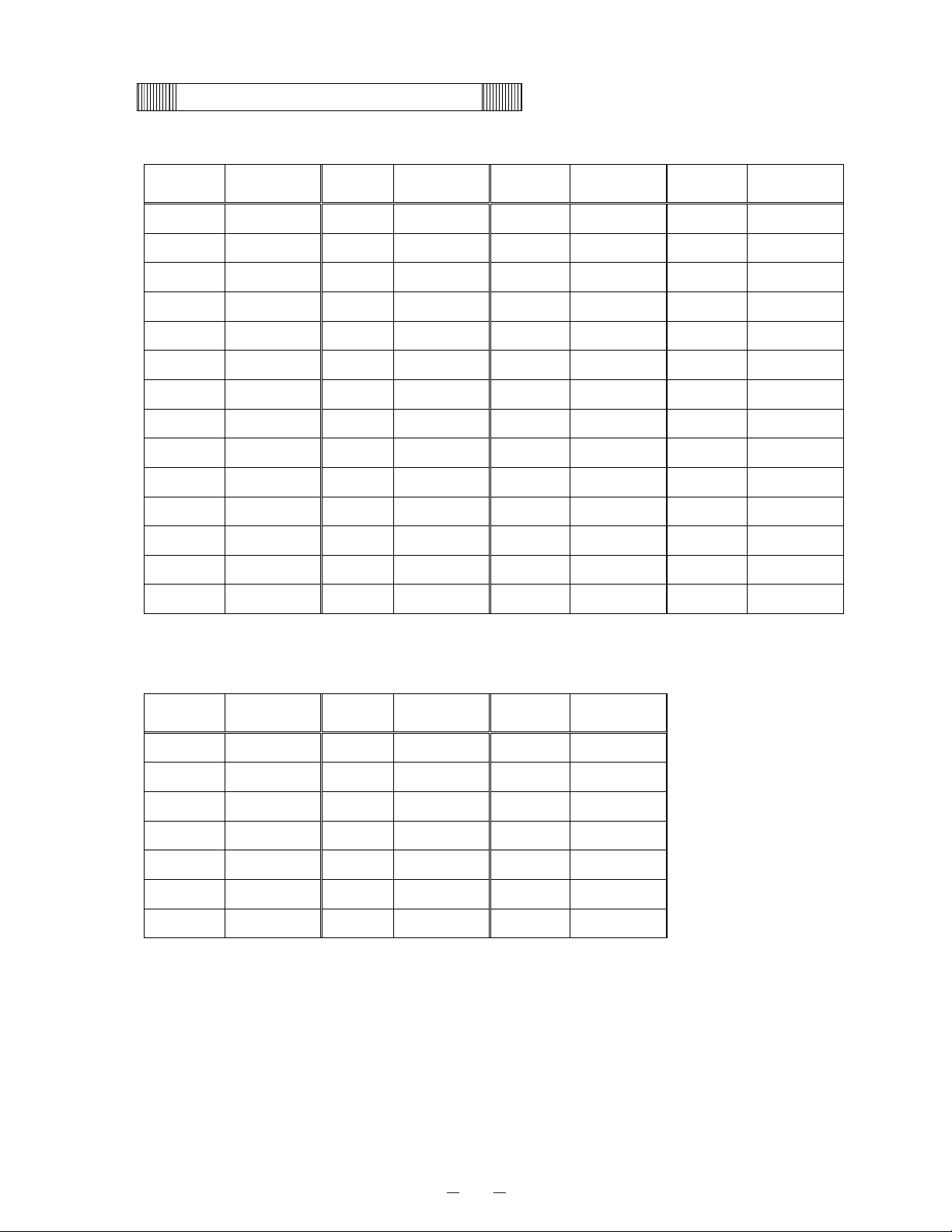
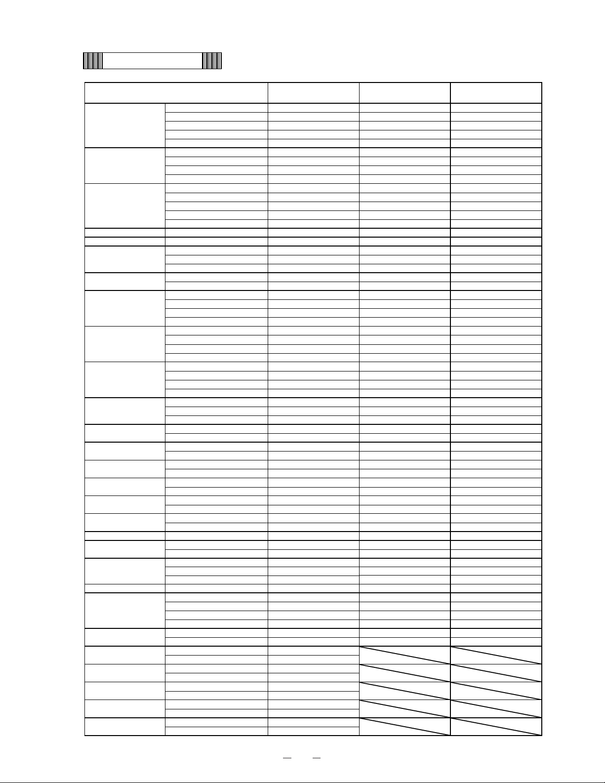
11
Specifications of sensor
The following shows the temperature in thermal sensor (502AT-1) and its resistance value.
Temp.
(C)
Resistance
Value (kΩ)
Temp.
(C)
Resistance
Value (kΩ)
Temp.
(C)
Resistance
Value (kΩ)
Temp.
(C)
Resistance
Value (kΩ)
−50
154.5
−36
71.80
−22
35.65 0 13.29
−49
145.9
−35
68.15
−21
33.99 5 10.80
−48
137.8
−34
64.71
−20
32.43 10 8.84
−47
130.2
−33
61.48
−19
30.92 15 7.20
−46
123.1
−32
58.43
−18
29.50 20 6.01
−45
116.5
−31
55.55
−17
28.14 25 5.00
−44
110.2
−30
52.84
−16
26.87 30 4.17
−43
104.4
−29
50.23
−15
25.65 35 3.50
−42
98.87
−28
47.77
−14
24.51 40 2.96
−41
93.70
−27
45.45
−13
23.42 45 2.51
−40
88.85
−26
43.26
−12
22.39 50 2.13
−39
84.18
−25
41.19
−11
21.41 55 1.82
−38
79.80
−24
39.24
−10
20.48 60 1.56
−37
75.67
−23
37.39
−5
16.43 65 1.35
The following shows the temperature in thermal sensor (PT1000ȍ) and its resistance value.
Temp.
(C)
Resistance
Value (Ω)
Temp.
(C)
Resistance
Value (Ω)
Temp.
(C)
Resistance
Value (Ω)
−140
450.83
−70
729.99 0 1000.0
−130
491.47
−60
769.02 10 1038.0
−120
531.83
−50
807.87 20 1076.0
−110
571.92
−40
846.58 30 1113.8
−100
611.76
−30
885.13 40 1151.4
−90
651.38
−20
923.55 50 1189.0
−80
690.78
−10
961.84 60 1226.4
Page 15

12
Connections on PCB
The following shows the connections of connectors on the Temp. controller PCB.
Connector Connects to Usage
CN1 Switching power supply To supply the power to PCB.
CN2 Network interface To connect to MTR-480(option)
CN3
Remote alarm terminal
#1: COM.
#2: N.O.
#3: N.C.
Remote alarm contact outputs.
In normal condition, open for #1-#2 and
closed for #1-#3.
CN4
#1-#2:Temp. control relay
#3-#4:Heater relay
To control internal temperature (12VDC)
To supply the power to Cap. tube heater
(12VDC)
CN5
#1-#5: Switch PCB
#6-#7: Buzzer
To connect to each switch
CN6 Display PCB To connect to each LED
CN7
#1-#2: Door switch
#5-#6: AT sensor
#7-#8: Filter sensor
#9-#10: Cascade sensor
To control the door switch
To detect the ambient temperature
To detect the temperature in condenser outlet pipe.
To detect the temperature in cascade.
CN8
#1-#2: Battery
(#1:6V #2:Battery switch)
#3-#4: Transformer
To supply the power during power failure
To supply the power to PCB.
CN9 #1-#2: H. Comp. relay To control compressor H ON/OFF (12VDC)
CN10 Unused
CN11 #1-#3: Temp. sensor To detect the internal temperature.
Page 16

13
㩷 Wiring Diagram 㩷
Page 17

14
Page 18
15
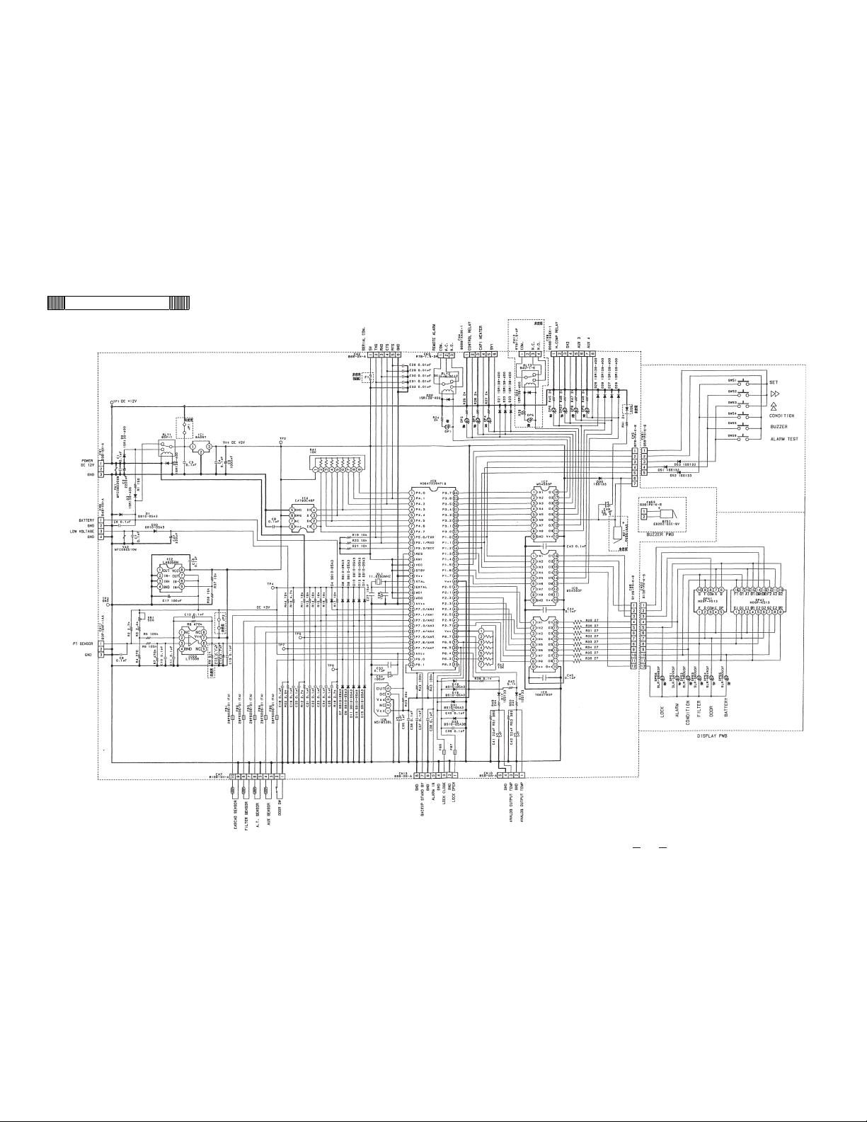
㩷 Circuit Diagram 㩷
Page 19
16
㩷 Control specification
1. Key and Switch
BUZZER : In alarm condition, buzzer stops sounding with this key pressed.
Remote alarm output and alarm message would not be off.
During the power failure (battery back-up), press the key to show the
present temperature of PT sensor.
ALARM TEST : With this key pressed to activate alarm test mode to be forcibly step into
alarm condition (ALARM lamp blinks, intermittent buzzer beeps, digital LED
goes off and remote alarm inputs).
After approx. 90seconds then, normal condition retrieves with Auto Return
function.
With the battery switch turns off, “E09” blinks on the display.
SET : Press this key once to activate set mode (2
nd
digit in LED blinks), press the
key again to store the value to be changed.
With Key Lock setting mode (“L 0” or “L 1” is displayed), press the key to
store the value to be changed.
STATUS : During STATUS lamp is lit, press this key to display status code among ‘- -
1’, ‘- - 2’ and ‘- - 3’.
During setting mode, the blinking digit shifts among the 1
st
digit or the 2nd
digit or 3
rd
digit.
During setting mode, count the blinking digit up. In PV display, press the
key over 5 seconds to enter the function mode. (“F00” is displayed)
2. Temperature control
Setting range :
-50㷄~-90㷄
Display range :
-180㷄~+50㷄
Setting procedure : Press SET key and set the required value with key and key.
Press SET key to store the set value.
Out of setting range : If you try to set the value which is out of temperature setting range, it is
unacceptable with buzzer beeps for 1second.
3. Temperature alarm
Setting range :
High temperature alarm … +5㷄~+20㷄 (Initial setting: 10㷄)
Low temperature alarm …. -5㷄~-20㷄 (initial setting: -10㷄)
Setting procedure : Keep pressing key over 5 seconds to enter function mode (F00).
Input “F01” for high temperature alarm or “F02” for low temperature
alarm. Press SET key to set the value to be changed with the 1
st
digit
blinks. Press SET key again to store the value in the non-volatile
memory.
Out of setting range : If you try to set the value which is out of alarm setting range, it is
unacceptable with buzzer beeps for 1 second.
4. Key Lock mode and Function mode
A) Key Lock mode
Setting range : 0, 1
Setting procedure: In PV display, keep pressing key over 5 seconds to enter into Key
Lock mode. (“L_0” or “L_1” is displayed. initial: L_0) with “0” or “1” blinks.
Change the value with key and press SET key to store the value in
the non-volatile memory.
Page 20

17
B) Function mode
Setting range : 00~32
Display range : 00~39
00, 16 and 33~39 are unavailable.
Setting procedure : In PV display, keep pressing key over 5 seconds to enter function
mode (F00 is displayed). Change the blinking 1
st
digit to desired function
code with key and key. Press SET key to be function code
available.
If you input 00 and 16 then press SET key, automatically revert to PV
display.
Out of setting range : If you try to input F33~F39, it is unacceptable to change with
automatically revert to PV display.
5. Warning function
Door alarm : Leave the outer door open and DP54 (red lamp) is lit. Buzzer beeps
intermittently after 1~15 min. (Door alarm setting time) has passed. Initial
setting time is 2 min. Buzzer does not activate simultaneously with
remote alarm terminal output. Once press BUZZER key to stop buzzer
beeping, buzzer does not beep again unless alarming condition get
backs.
High temp. alarm : When PV is reached at SV+SV
H
(high temp. alarm SV) +1 or higher,
ALARM lamp and LED display blinks, intermittent buzzer beeps with
approx. 15 minutes of delay and remote alarm output turns on.
When PV is reached at SV+ SV
H
or lower, ALARM lamp and LED display
go off, buzzer stops beeping and remote alarm output turns off.
If you press BUZZER key, the buzzer stops beeping instead remote
alarm output does not turn off.
Low temp. alarm : When PV is reached at SV-SV
L
(low temp. alarm SV) -1 or lower, ALARM
lamp and LED display blinks, intermittent buzzer beeps with approx. 15
minutes of delay and remote alarm output turns on.
When PV is reached at SV- SV
L
or lower, ALARM lamp and LED display
go off, buzzer stops beeping and remote alarm output turns off.
If you press BUZZER key, the buzzer stops beeping instead remote
alarm output does not turn off.
Filter blockage :
With the filter sensor temperature is reached at 48.0㷄 or higher, FILTER
lamp is lit with buzzer beeps intermittently.
With the filter sensor temperature is reached at 43.0㷄 or lower, FILTER
lamp goes off and buzzer stops beeping.
6. Other function
Cascade control : Compressor (L) is allowed to turn on when the cascade sensor
temperature is reached at -34.1㷄 or lower during pull-down.
Compressor (L) is allowed to turn off when the cascade sensor
temperature is reached at -12.0㷄 or higher during pull-up.
Auto Return : If there is not any key operation for 90 seconds in each setting mode,
Key Lock mode and Function mode, automatically reverts to PV mode.
Note) Auto Return is not worked in F09 and F10.
Sensor temperature : F12: Temperature of temp. sensor is displayed
(Ex. -80.2㷄㩷 㸢㩷 displayed as ‘80.2’)
F13: Temperature of cascade sensor is displayed.
(Ex. -34㷄㩷 㸢㩷 displayed as ‘-34㷄’)
F14: Temperature of filter sensor is displayed.
(Ex. 67㷄㩷 㸢㩷 displayed as ‘067’)
F15: Temperature of AT sensor is displayed.
(Ex. 30㷄㩷 㸢㩷 displayed as ‘030’)
Page 21

18
Battery accumulating
time :
F03: Battery accumulating time is displayed.
(Ex. 2years and 6months consumed 㸢㩷 displayed as ‘02.5’)
The display shows ’02.8’ to inform the battery exhaustion.
Replace with new battery.
<Reset of accumulating time>
Step into F06. Input ‘409’ and press SET key to turn the display
to ’00.0’ with BATTERY lamp goes off.
Condensing fan
motor accumulating
time :
F32: Condensing fan motor accumulating time is displayed.
(Ex. 5years and 6months consumed 㸢 displayed as ’05.5’)
<Reset of accumulating time>
Step into F06. Input ‘419’ and press SET key to turn the display
to ’00.0’ with DP55 lamp goes off.
Note) Notice of condensing fan motor accumulating time is prior to
notice of battery accumulating time.
ROM version :
F30: ROM version is displayed (Ex. Ver. 1.00 㸢㩷 displayed as “1.00”)
Monitor of status : DP52 (orange lamp) is lit in the following status;
Status 1; When the ambient temperature is over 35.0C or lower than
0C. Press STATUS key once to display ‘- - 1’.
Status 2; When the power source voltage is less than 2.01 VDC
between TP7 and TP3. Press STATUS key once to display
‘- - 2’,
Status 3; When running rate of refrigerating circuit is higher than
usual.
When diagnose value of running rate is 95% or higher, the display
shows ‘- - 3’.
Display on temperature indicator:
Status code displayed is changed every few seconds if two or three
status shown at the same time.
order: (‘- - 1’ 㸢 ‘- - 2’ 㸢㩷 ‘- - 3’ 㸢 ‘- - 1’ …… )
7. Function mode
F00 Automatically revert to PV display
F01 SV
H
(high temp. alarm SV) setting
F02 SV
L
(low temp. alarm SV) setting
F03 Battery accumulating time display
F04 Door alarm delay time setting
F05 Compressor (H)/(L) delay time setting
F06 Service code input (code: 384)
F07 * Temperature Zero Adjustment
F08 * Cascade sensor Zero Adjustment
F09 Factory test mode …… Unavailable
F10 Factory test mode …… Unavailable
F11 Factory test mode …… Unavailable
F12 * Display of temperature of temp. sensor
F13 * Display of temperature of cascade sensor
F14 * Display of temperature of filter sensor
F15 * Display of temperature of AT sensor
F16 Automatically revert to PV display
F17 * Model code setting (Initialization of non-volatile ROM and memory)
F18 * Capillary heater is forcibly turned on/off
F19 Factory test mode …… Unavailable
F20 * Setting for Diagnose value of running rate …… Unavailable
F21 Communication ID set
F22 Communication mode set
F23 * Display of power supply voltage
F24 Remote alarm terminal output
F25 Ring-back time set
Page 22

19
F26 * Display of actual operation rate
F27 * Display of calculated running rate
F28 * Display of delay time of permission for measuring running rate (2 hrs timer)
F29 * Display of delay time of permission for measuring running rate (8 hrs timer)
F30 * ROM version is displayed
F31 * Filter alarm
F32 Display of condensing fan motor accumulating time
F33~F39 Unused
Setting
procedure:
In PV display, keep pressing key over 5seconds to display “F00”.
Input the desired function code with key and key.
Press SET key to be function mode available.
* … You should input service code in F06 beforehand.
To cancel service code, input “000” in F06 or turn the power off.
F00: <Purpose> Simply passing through if entered by mistake.
<Operation> Press SET key in “F00” displayed to revert to PV display.
F01: <Purpose> SV
H
(high temp. alarm SV) setting
<Operation> Input F01 and press SET key to display “010” (initial value).
Set the value in the range “005”~“020” with key. Press SET key
to store the value and revert to PV display.
F02: <Purpose> SV
L
(low temp. alarm SV) setting
<Operation> Input F02 and press SET key to display “-10” (initial value).
Set the value in the range “-05”~“-20” with key. Press SET key to
store the value and revert to PV display.
F03: <Purpose> Battery accumulating time is displayed
<Operation> Input F03 and press SET key to display alternately F03 with “00.0”
(in case battery used for a month or less). Press SET key to revert to
PV display.
F04: <Purpose> Door alarm delay time is set
<Operation> Press SET key in “F04” displayed to display ‘002’ (initial setting).
Change your desired value among ‘001’~’015’ with key and
key and press SET key to store the value and revert to PV
display.
F05: <Purpose> Compressor (H) / (L) is turned on with forcibly delayed (by minute
increment) when the power retrieves from the power failure.
<Operation> Input “F05” and press SET key to display “002” (initial).
Change the value in the range “002”~”015” with key and key.
Press SET key to store the value and revert to PV display.
F06: <Purpose> Dividing F-code for customer used from service
<Operation> Input F06 and press SET key to display “000” (initial value).
Set to “384” with key and key. Press SET key to store the
value and revert to PV display.
<Cancel> Input F06 and press SET key to display “384”.
Change to “000” with key and key. Press SET key to store
the value and revert to PV display.
Turn the power off then on to revert to “000”. (not stored in
non-volatile memory)
Note) “384” is storied in non-volatile memory during battery back-up.
(battery SW is ON)
F07: <Purpose> To match temperature of temp. sensor with temperature of center at
the chamber.
<Operation> Input service code in F06 prior to use this mode.
Input F07 and press SET key to display “00.0” (initial value).
Page 23

20
Change to the desired value in the range “-4.9”~”04.9” with key
and key.
Press SET key to store the value and revert to PV display.
F08: <Purpose> To calibrate temperature of cascade sensor
<Operation> Input service code in F06 prior to use this mode.
Input F08 and press SET key to display “00.0” (initial value).
Change to the desire value in the range “-9.9”~”09.9” with key
and key.
Press SET key to store the value and revert to PV display.
F12: <Purpose> To display the temperature of temp. sensor
<Operation> Input service code in F06 prior to use this mode.
Input F12 and press SET key to display alternately F12 and “XX.X”
(present internal temperature). Press SET key to revert to PV
display. 3 digits indication. Minus “-“ is not indicated.
Ex) “-85.5㷄” 㸢㩷 indicated as “85.5”
F13: <Purpose> To display the temperature of cascade sensor
<Operation> Input service code in F06 prior to use this mode.
Input F13 and press SET key to display alternately F13 and “XX.X”
(present temperature of cascade sensor). Press SET key to revert to
PV display.
F14: <Purpose> To display the temperature of filter sensor
<Operation> Input service code in F06 prior to use this mode.
Input F14 and press SET key to display alternately F14 and “XX.X”
(present temperature of filter sensor). Press SET key to revert to PV
display.
F15: <Purpose> To display the temperature of AT sensor
<Operation> Input service code in F06 prior to use this mode.
Input F15 and press SET key to display alternately F15 and “XX.X”
(present temperature of AT sensor). Press SET key to revert to PV
display.
F16: <Purpose> Simply passing through if entered by mistake.
<Operation> Press SET key in “F16” displayed to revert to PV display.
F17: <Purpose> Non-volatile memory initialization, model code change
<Operation> Service code should be input in F06 prior to use this mode.
Input F17 and press SET key to display “001”. Change the value
with key and key. Press SET key to store and revert to PV
display.
Model code ‘007’: MDF-U53V/U53VC
F18: <Purpose> To turn capillary heater forcibly on (or off)
<Operation> Service code should be input in F06 prior to use this mode.
Input F18 and Press SET key to display “000” (initial).
Change to desire value “000” or “001” with key and key.
Press SET key to store the value and revert to PV display.
000: Capillary heater is turned on to off, or turned off to on
001: Capillary heater is forcibly turned off
F21: <Purpose> Serial communication ID setting
<Operation> Input F21 and press SET key to display “000” (initial).
Change the value in the range “001”~”255” with key and key.
F22: <Purpose> Serial communication mode setting
<Operation> input F22 and press SET key to display “000” (initial value)
Change the value with key and key.
Page 24

21
Press SET key to store the value and revert to PV display.
Control mode (the 3
rd
digit)
0: Local (initial)
1: Remote
Baud rate (the 2
nd
digit)
0: 2400bps (initial)
1: 4800bps
2: 9600bps
Note) You cannot be changed SV if control mode is set in “Remote”.
F23: <Purpose> To display the power supply voltage (Unit: %)
<Operation> Service code should be input in F06 prior to use this mode.
Input F23 and press SET key to display F23 and ‘xxx’ (present
power supply voltage) alternately. Press SET key to revert to PV
display.
F24: <Purpose> To control remote alarm output
<Operation> Input F24 and Press SET key to display “000” (initial).
Change to the desired value with key and key.
Press SET key to store the value and revert to PV display.
000: Remote alarm is outputted simultaneously with buzzer
001: Remote alarm is not outputted simultaneously with buzzer
F25: <Purpose> Alarm auto recovery time setting
<Operation> Input F25 and press SET key to display “030” (initial).
Change to the desired value with key and key.
Press SET key to store the value and revert to PV display.
000: Auto recovery OFF
010: Recovers after 10min. passed
020: Recovers after 20min. passed
030: Recovers after 30min. passed
(initial)
040: Recovers after 40min. passed
050: Recovers after 50min. passed
060: Recovers after 60min. passed
F26: <Purpose> Actual running rate is displayed (unit: %)
<Operation> Service code should be input in F06 prior to use this mode.
Input F26 and press SET key to display alternately F26 with “XXX”
(present actual running rate).
Press SET key to revert to PV display.
F27: <Purpose> Calculated running rate is displayed
<Operation> Service code should be input in F06 prior to use this mode.
Input F27 and press SET key to display alternately F27 with “XXX”
(present calculated running rate).
Press SET key to revert to PV display.
F28: <Purpose> To display delay time of permission of measuring running rate
(2hrs timer; 000~120 min)
<Operation> Service code should be input in F06 prior to use this mode.
Input F28 and press SET key to display F28 and ‘xxx’ (present count
value) alternately. Press SET key to revert to PV.
F29: <Purpose> To display delay time of permission of measuring running rate
(8hrs timer; 000~480 min)
<Operation> Service code should be input in F06 prior to use this mode.
Input F29 and press SET key to display F29 and ‘xxx’ (present count
value) alternately. Press SET key to revert to PV.
F30: <Purpose> ROM version is displayed
<Operation> Service code should be input in F06 prior to use this mode.
Input F30 and press SET key to display alternately F30 with “X.XX”
(present ROM version).
Press SET key to revert to PV display.
Page 25

22
F31: <Purpose> Buzzer setting during filter alarm
<Operation> Input F31 and press SET key to display “001” (initial).
Change to the desired value with key and key.
Press SET key to revert to PV display.
000: Buzzer off
001: Buzzer on
F32: <Purpose> To display accumulation time of condensing fan motor
<Operation> Input F32 and press SET key to display F32 and ‘xx.x’ (accumulation
time) alternately. Press SET key to revert to PV display.
8. Differential (The point of compressor ON and OFF )
COMP ON:
COMP OFF:
SV +0.4㷄
SV -2.2㷄 (for SV is -90㷄~-60㷄), SV -0.5 (for SV is -59㷄~-50㷄)
9. Offset value
1) PV+0.5㷄 is the offset value to adjust the difference between temperature of temp. sensor
and the center of internal chamber.
2) PVat + (-3.0C) is the offset value to correct the ambient temperature.
*Note) PVat = Temperature of AT sensor
10. Remote alarm terminal
In normal condition:
㸣
In alarm condition &
power failure :
Remote alarm contact is N.O. N.C.
㸣
Remote alarm contact is N.C. N.O.
11. Cycling of High stage compressor
If the filter sensor is higher than or equal to 60㷄, the High stage compressor will be turned off.
When the filter sensor is within 10㷄 of the ambient temperature sensor, the High stage
compressor will be allowed to turn back on.
12. Sensor failure
(1) Temp. sensor
Open circuit:
E01 and 50㷄 are displayed alternately, the buzzer beeps intermittently
and remote alarm contact outputs.
The compressor would be allowed to turn on.
Press BUZZER key to stop the buzzer beeping.
Short circuit:
E02 and -170㷄>PV>-180㷄 are displayed alternately, the buzzer beeps
intermittently and remote alarm contact outputs.
The compressor would be allowed to turn on.
Press BUZZER key to stop the buzzer beeping.
(2) Cascade sensor
Open circuited: E03 and PV are displayed alternately, the buzzer beeps intermittently
and remote alarm contact outputs.
The resistance value would be 㺙㱅 and temperature would be -34.1㷄
or lower. Compressor (L) is not forcibly turned off.
Press BUZZER key to stop the buzzer beeping.
Short circuited: E04 and PV are displayed alternately, the buzzer beeps intermittently
and remote alarm contact outputs.
Press BUZZER key to stop the buzzer beeping.
The resistance value would be 0㱅 and temperature would be -12㷄 or
higher that causes to be compressor (L) failure. Compressor (L) is
forcibly turned off.
Page 26

23
(3) Filter sensor
Open circuited: E05 and PV are displayed alternately, the buzzer beeps intermittently
and remote alarm contact outputs.
Press BUZZER key to stop the buzzer beeping.
Short circuited: E06 and PV are displayed alternately, the buzzer beeps intermittently
and remote alarm contact outputs.
Press BUZZER key to stop the buzzer beeping.
(4) AT sensor
Open circuited: E07 and PV are displayed alternately, the buzzer beeps intermittently
and remote alarm contact outputs.
Press BUZZER key to stop the buzzer beeping.
Short circuited: E08 and PV are displayed alternately, the buzzer beeps intermittently
and remote alarm contact outputs.
Press BUZZER key to stop the buzzer beeping.
(5) Abnormal
condenser temp.
E10 and PV are displayed alternately, the buzzer beeps intermittently
and remote alarm contact outputs.
Press BUZZER key to stop the buzzer beeping.
When E10 is shown on the display, the compressor (H) is forcibly turned
off. When E10 is not shown, the compressor (H) is permitted to turn on.
(6) Error code priority
No.1: Temp. sensor failure (E01 or E02)
No.2: Cascade sensor failure (E03 or E04)
No.3: Filter sensor failure (E05 or E06)
No.4:
No.5:
AT sensor failure (E07 or E08)
Abnormal condenser temperature (E10)
(7) Standard to judge sensor failure
PT sensor:
49.9㷄 or higher with E01 displayed (open circuited)
-170㷄 or lower with E02 displayed (short circuited)
Cascade sensor:
-60㷄 or lower with E03 displayed (open circuited)
60㷄 or higher with E04 displayed (short circuited)
Filter sensor:
-60㷄 or lower with E05 displayed (open circuited)
130㷄 or higher with E06 displayed (short circuited)
AT sensor:
-60㷄 or lower with E07 displayed (open circuited)
60㷄 or higher with E08 displayed (short circuited)
Filter sensor: 60㷄 or higher with E10 displayed
13. Cycle to turn capillary heater on
Cycle: Every 18 hours
Period to turn on: 8 minutes (For factory use, unnecessary to change)
Capillary heater is permitted to turn on after 9seconds later since
compressor L was switched to turn off.
With the compressor L keeps turning on for 60minutes, the compressor L
turns off after 1minute passed then and capillary heater is forcibly turned
on.
14. When the power is supplied (without battery)
Compressor H: Compressor H turns on with 2minutes (initial value) of delay after the
power was supplied. Compressor H runs with regardless of PV.
Compressor L:
In PV䋾SV (when the cascade sensor temperature is -34.1㷄 or lower),
compressor L turns on with 2minutes (initial value) of delay after the
power was supplied.
In PV䋾SV (when the cascade sensor temperature is -34.0㷄 or higher),
compressor L turns on with 2minutes (initial value) of delay after the
power was supplied and cascade temperature is reached at -34.1㷄.
*Note) Delay time of both compressor H and L cannot be set individually.
Setting data: The setting data initialized in F17 is retrieved in non-volatile memory.
Page 27

24
15. Other specifications
(1) Lamp specifications:
<Control PCB>
DP1: Orange lamp
Goes off: High/low temp. alarm, sensor failure, power failure
Lit : Not in alert condition
DP2: Green lamp
Goes off: Compressor L turns off. (normal condition)
Lit : Compressor L turns on.
DP3: Red lamp
Goes off: Capillary heater turns off. (normal condition)
Lit : Capillary heater turns on.
DP4: Yellow lamp
Goes off: Inoperative
Lit: Inoperative
DP6: Green lamp
Goes off: Compressor H turns off. (normal condition)
Lit : Compressor H turns on.
<Display PCB>
DP51: Red lamp
Goes off: Not in alarm condition (normal condition)
Blinks : High/low temp. alarm (without delay), or sensor failure,
or power failure
DP52: Orange lamp
Goes off: Inoperative
Lit : Inoperative
Blinks : In F11 performed
DP53: Orange lamp
Goes off: Not in filter alarm (normal condition)
Lit : In filter alarm
Blinks : In F11 performed
DP54: Red lamp
Goes off: Inoperative
Lit : Inoperative
Blinks : In F11 performed
DP55: Orange lamp
Goes off: Length of battery used is 2.8yrs or less (normal condition)
Fan motor accumulation time is less than 5.6yrs
Lit : Length of battery used is 2.8yrs or over
Blinks : In F11 performed
Fan motor accumulation time is equal or more than 5.6yrs
DP56: Green lamp
Goes off: Inoperative
Lit : Inoperative
Blinks : In F11 performed
(2) Buzzer specifications:
High/low temp. alarm: Intermittent tone emitted with delay
Sensor failure: Intermittent tone emitted when EXX (XX=01~08) displayed
Power failure: Intermittent tone emitted with DPA1 and DPA2 go off
Key quick: Short tone emitted if available
Input out of range: 1second continuous tone emitted
Filter alarm: Intermittent tone emitted with DP53 lit (in F31:001, initial setting)
Compressor abnormal
warming up :
Intermittent tone emitted with E10 displayed
Page 28

25
Control panel
Latch 'O
p
en'
Inner door handle
Boost BOX
(
MDF-U53VC onl
y)
Power transformer
(
MDF-U53VC onl
y)
Parts layout
Door latch
Handle
Fan motor
Filter sensor
Page 29

26
<Grille> Filte
r
A
T sensor
Power switch
<Electrical BOX>
Remote alarm
Main PCB
Switchin
g p
ower suppl
y
Running capacitor H
Startin
g
capacitor H
Runnin
g
capacitor L Starting capacitor L
12P terminal
Page 30

27
Test data
㪤㪛㪝㪄㪬㪌㪊㪭㩷㪫㪼㫄㫇㪼㫉㪸㫋㫌㫉㪼㩷㪺㪿㪸㫉㪸㪺㫋㪼㫉㫀㫊㫋㫀㪺㫊
㪄㪈㪇㪇
㪄㪏㪇
㪄㪍㪇
㪄㪋㪇
㪄㪉㪇
㪇
㪉㪇
㪋㪇
㪇 㪌 㪈㪇 㪈㪌
䌔䌩䌭䌥䋨䌨䌯䌵䌲䋩
㪫㪼㫄㫄㫇㪼㫉㪸㫋㫌㫉㪼㩿㷄㪀
㪧㫌㫃㫃㪄㪛㫆㫎㫅
㪧㫌㫃㫃㪄㪬㫇
㪘㪫
㪤㪛㪝㪄㪬㪌㪊㪭㩷㪟㪆㪣㩷㪜㪭㪘㩷㪦㪬㪫㩷㪫㪼㫄㫇㪼㫉㪸㫋㫌㫉㪼㩷㫀㫅㩷㫇㫌㫃㫃
㪄㪈㪇㪇
㪄㪏㪇
㪄㪍㪇
㪄㪋㪇
㪄㪉㪇
㪇
㪉㪇
㪋㪇
㪇 㪌 㪈㪇 㪈㪌
㪫㫀㫄㪼㩿㪿㫆㫌㫉㪀
㪫㪼㫄㫇㪼㫉㪸㫋㫌㫉㪼㩿㷄㪀
㪟㪜㪭㪘㪦㪬㪫
䌌㪜㪭㪘㪦㪬㪫
㪧㫌㫃㫃㪄㪛㫆㫎㫅
㪘㪫
㪘㪫
㪧㫌㫃㫃㪄㪬㫇
㪧㫌㫃㫃㪄㪛㫆㫎㫅
㪘㪫
㪟㩷㪜㪭㪘㩷㪦㪬㪫
㪣㩷㪜㪭㪘㩷㪦㪬㪫
㪧㫌㫃㫃㪄㪛㫆㫎㫅
Page 31

28
㪤㪛㪝㪄㪬㪌㪊㪭㩷㪬㫅㫀㫋㩷㫇㫉㪼㫊㫊㫌㫉㪼
㪇㪅㪇
㪇㪅㪌
㪈㪅㪇
㪈㪅㪌
㪉㪅㪇
㪉㪅㪌
㪇㪊㪍㪐㪈㪉㪈㪌
㪫㫀㫄㪼㩿㪿㫆㫌㫉㪀
㪧㫉㪼㫊㫊㫌㫉㪼㩿㪤㪧㪸㪀
㪍㪇㪟㫑㪃㪘㪫㪊㪌㷄
㪤㪛㪝㪄㪬㪌㪊㪭㩷㪧㫆㫎㪼㫉㩷㪺㫆㫅㫊㫌㫄㫇㫋㫀㫆㫅
㪇㪅㪇
㪈㪅㪇
㪉㪅㪇
㪊㪅㪇
㪋㪅㪇
㪌㪅㪇
㪍㪅㪇
㪎㪅㪇
㪏㪅㪇
㪇㪊㪍㪐㪈㪉㪈㪌
㪫㫀㫄㪼㩿㪿㫆㫌㫉㪀
㪚㫌㫉㫉㪼㫅㫋㩿㪘㪀
㪇㪅㪇
㪇㪅㪌
㪈㪅㪇
㪈㪅㪌
㪉㪅㪇
㪉㪅㪌
㪊㪅㪇
㪧㫆㫎㪼㫉㩷㪺㫆㫅㫊㫌㫄㫇㫋㫀㫆㫅㩷㩿㫂㪮㪀
㫂㪮
㪟㪄㫇㪻
㪣㪄㫇㪻
㪟㪄㫇㫊
㪣㪄㫇㫊
Page 32

29
Temperature Uniformity 䊶 䊶 䊶 MDF-U53V
䌾Reference䌾
Condition: SV-80㷄
A
T30㷄
Load: No load
Measuring point: Center
䋪䋺1/2䌈䌡䌩䌲
㪄㪎㪐㪅㪉㷄
㪄㪏㪇㪅㪎㷄
㪁㪄㪎㪐㪅㪐㷄
㪄㪎㪎㪅㪉㷄
㪄㪎㪍㪅㪊㷄
Page 33

30
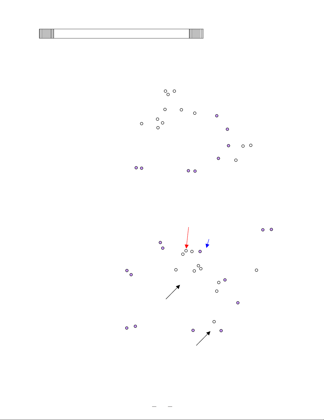
<Sample load test>
Test conditions: 500ml water x 60 bottles (30L in total)
Measuring point: a, b, c and d as figure shows
Bottom: 500ml x 15bottles
Lower: 500ml x 15bottles
Middle: 500ml x 15bottles
Upper: 500ml x 15bottles
(Front view)
500ml x 60bottles (30L in total)
䌡
䌢
㪺
䌤
㪤㪛㪝㪄㪬㪌㪊㪭㩷㪪㪸㫄㫇㫃㪼㩷㫃㫆㪸㪻㩷㫋㪼㫊㫋㩷䋨㪪㪭㪄㪏㪇㪀
㪄㪐㪇
㪄㪎㪇
㪄㪌㪇
㪄㪊㪇
㪄㪈㪇
㪈㪇
㪊㪇
㪇 㪍 㪈㪉 㪈㪏 㪉㪋 㪊㪇 㪊㪍
䌔䌩䌭䌥䋨䌨䌲䋩
䌴䌥䌭䌰䋨㷄䋩
㪟㪜㫍㪸㩷䌯䌵䌴
䌌㪜㫍㪸㩷䌯䌵䌴
㪣䌯䌡䌤䇭䌡
㪣䌯䌡䌤䇭䌢
㪣䌯䌡䌤䇭䌣
㪣䌯䌡䌤䇭䌤
Page 34

31
MDF-U53V䇭Temperature after the unit reaches at -80㷄
㪄㪐㪇
㪄㪏㪇
㪄㪎㪇
㪄㪍㪇
㪄㪌㪇
㪄㪋㪇
㪄㪊㪇
㪄㪉㪇
㪇 㪍㪇 㪈㪉㪇 㪈㪏㪇 㪉㪋㪇 㪊㪇㪇 㪊㪍㪇
time(min)
㪫㪼㫄㫇㪅䋨㷄䋩
䌬䌯䌡䌤 䌤
䌬䌯䌡䌤 䌡
䌬䌯䌡䌤 䌢
䌬䌯䌡䌤 䌣
Leva out
Heva out
㪤㪛㪝㪄㪬㪌㪊㪭 Sample load test (SV-50)
㪄㪐㪇
㪄㪏㪇
㪄㪎㪇
㪄㪍㪇
㪄㪌㪇
㪄㪋㪇
㪄㪊㪇
㪄㪉㪇
㪇㪉㪋㪍㪏㪈㪇
䌔䌩䌭䌥䋨䌨䌲䋩
㫋㪼㫄㫇䋨㷄䋩
Heva out
Leva out
䌬䌯䌡䌤 䌡
䌬䌯䌡䌤 䌤
䌬䌯䌡䌤 䌣
䌬䌯䌡䌤 䌢
Page 35

32
Instruction manual
x This section is extracted and printed from Instruction Manual.
x If you find out “Refer to page
ƔƔ
” in them, this page means not page in Service manual
but page in the lower corner of each page in the extract from Instruction manual.
This page number is not corresponded with serial number in Service manual.
Page 36

33
MDF-U73V
MDF-U73VC
MDF-U53V
MDF-U53VC
Ultra-Low Temperature Freezer
INSTRUCTION MANUAL
MDF-U73V/MDF-U73VC
Page 37

34
1
CONTENTS
INTRODUCTION P. 2
PRECAUTIONS FOR SAFE OPERATION P. 3
ENVIRONMENTAL CONDITIONS P. 7
FREEZER COMPONENTS P. 8
Control panel P.10
INSTALLATION SITE P.11
INSTALLATION P.12
START-UP OF UNIT P.13
CHAMBER TEMPERATURE SETTING P.14
KEY LOCK FUNCTION P.14
ALARM TEMPERATURE SETTING P.15
SETTING OF ALARM RESUME TIME P.16
REMOTE ALARM TERMINAL P.17
MONITOR OF FREEZER STATUS P.18
CHANGE OF COMPRESSOR DELAY TIME P.19
CHANGE OF DOOR ALARM DELAY TIME P.20
ALARMS & SAFETY FUNCTIONS P.21
ROUTINE MAINTENANCE
Cleaning of cabinet P.22
Cleaning of condenser filter P.22
Defrosting of inside wall P.23
TROUBLESHOOTING P.24
REPLACEMENT OF BATTERY P.25
DISPOSAL OF UNIT P.26
Recycle of battery P.26
TEMPERATURE RECORDER (OPTION) P.31
BACK-UP SYSTEM (OPTION) P.32
INVENTORY RACK (OPTION) P.33
SPECIFICATIONS P.34
PERFORMANCE P.36
SAFETY CHECK SHEET P.37
Page 38

35
2
INTRODUCTION
Ŷ Read this manual carefully before using the appliance and follow the instructions for safety operation.
Ŷ Sanyo never guarantee any safety if the appliance is used for any objects other than intended use or
used by any procedures other than those mentioned in this manual.
Ŷ Keep this manual in an adequate place to refer to it as necessary.
Ŷ The contents of the manual will be subjected to change without notice due to the improvement of
performance or functions.
Ŷ Contact Sanyo sales representative or agent if any page of the manual is lost or page order is incorrect.
Ŷ Contact Sanyo sales representative or agent if any point in this manual is unclear or if there are any
inaccuracies.
Ŷ No part of this manual may be reproduced in any form without the expressed written permission of
Sanyo.
Page 39

36
3
PRECAUTIONS FOR SAFE OPERATION
It is imperative that the user complies with this manual as it contains
important safety advice.
Items and procedures are described so that you can use this unit correctly and safely.
If the precautions advised are followed, this will prevent possible injury to the user and
any other person.
Precautions are illustrated in the following way:
WARNING
Failure to observe WARNING signs could result in a hazard to personnel
possibly resulting in serious injury or death.
CAUTION
Failure to observe CAUTION signs could result in injury to personnel and
damage to the unit and associated property.
Symbol shows;
㩷
this symbol means caution.
㩷
this symbol means an action is prohibited.
㩷
this symbol means an instruction must be followed.
Be sure to keep this manual in a place accessible to users of this unit.
< Label on the unit >
This mark is labeled on the cover in which the electrical components of high voltage
are enclosed to prevent the electric shock.
The cover should be removed by a qualified engineer or a service personnel only.
WARNING
As with any equipment that uses CO2 gas, there is a likelihood of oxygen depletion in the vicinity
of the equipment. It is important that you assess the work site to ensure there is suitable and
sufficient ventilation. If restricted ventilation is suspected, then other methods of ensuring a
safe environment must be considered. These may include atmosphere monitoring and warning
devices.
Page 40

37
4
PRECAUTIONS FOR SAFE OPERATION
Do not use the unit outdoors. Current leakage or electric shock may result if the unit is exposed to
rain water.
Only qualified engineers or service personnel should install the unit. The installation by
unqualified personnel may cause electric shock or fire.
Install the unit on a sturdy floor and take an adequate precaution to prevent the unit from
turning over. If the floor is not strong enough or the installation site is not adequate, this may result
in injury from the unit falling or tipping over.
Never install the unit in a humid place or a place where it is likely to be splashed by water.
Deterioration of the insulation may result which could cause current leakage or electric shock.
Never install the unit in a flammable or volatile location. This may cause explosion or fire.
Never install the unit where acid or corrosive gases are present as current leakage or electric
shock may result due to corrosion.
Always ground (earth) the unit to prevent electric shock. If the power supply outlet is not
grounded, it will be necessary to install a ground by qualified engineers.
Never ground the unit through a gas pipe, water main, telephone line or lightning rod. Such
grounding may cause electric shock in the case of an incomplete circuit.
Connect the unit to a power source as indicated on the rating label attached to the unit. Use
of any other voltage or frequency other than that on the rating label may cause fire or electric shock.
Never store volatile or flammable substances in this unit if the container cannot be sealed. These
may cause explosion or fire.
Do not insert metal objects such as a pin or a wire into any vent, gap or any outlet on the unit.
This may cause electric shock or injury by accidental contact with moving parts.
Use this unit in safe area when treating the poison, harmful or radiate articles. Improper use
may cause bad effect on your health or environment.
Turn off the power switch (if provided) and disconnect the power supply to the unit prior to
any repair or maintenance of the unit in order to prevent electric shock or injury.
Do not touch any electrical parts (such as power supply plug) or operate switches with a wet
hand. This may cause electric shock.
WARNING
Page 41

38
5
PRECAUTIONS FOR SAFE OPERATION
Ensure you do not inhale or consume medication or aerosols from around the unit at the time of
maintenance. These may be harmful to your health.
Never splash water directly onto the unit as this may cause electric shock or short circuit.
Never put containers with liquid on the unit as this may cause electric shock or short circuit when
the liquid is spilled.
Never bind, process, or step on the power supply cord, or never damage or break the power
supply plug. A broken supply cord or plug may cause fire or electric shock.
Do not use the supply cord if its plug is loose. Such supply cord may cause fire or electric shock.
Never disassemble, repair, or modify the unit yourself. Any such work carried out by an
unauthorized person may result in fire, or electric shock or injury due to a malfunction.
Disconnect the power supply plug if there is something wrong with the unit. Continued
abnormal operation may cause electric shock or fire.
When removing the plug from the power supply outlet, grip the power supply plug, not the cord.
Pulling the cord may result in electric shock or fire by short circuit.
Disconnect the power supply plug before moving the unit. Take care not to damage the power
cord. A damaged cord may cause electric shock or fire.
Disconnect the power plug when the unit is not used for long periods. Keeping the connection
may cause electric shock, current leakage, or fire due to the deterioration of insulation.
If the unit is to be stored unused in an unsupervised area for an extended period, ensure that
children do not have access and that doors cannot be closed completely.
The disposal of the unit should be accomplished by appropriate personnel. Remove doors to
prevent accidents such as suffocation.
Do not put the packing plastic bag within reach of children as suffocation may result.
WARNING
Page 42

39
6
PRECAUTIONS FOR SAFE OPERATION
Use a dedicated power source (a dedicated circuit with a breaker) as indicated on the rating label
attached to the unit. A branched circuit may cause fire resulting from abnormal heating.
Connect the power supply plug to the power source firmly after removing the dust on the plug.
A dusty plug or improper insertion may cause a heat or ignition.
Never store corrosive substances such as acid or alkali in this unit if the container cannot be
sealed. These may cause corrosion of inner components or electric parts.
Check the setting when starting up of operation after power failure or turning off of power
switch. The stored items may be damaged due to the change of setting.
Be careful not to tip over the unit during movement to prevent damage or injury.
Prepare a safety check sheet when you request any repair or maintenance for the safety of service
personnel.
CAUTION
Page 43

40
7
ENVIRONMENTAL CONDITIONS
This equipment is designed to be safe at least under the following conditions (based on the IEC-1010-1):
Ŷ Indoor use;
Ŷ Altitude up to 2000 m;
Ŷ Ambient temperature 5
o
C to 40oC
Ŷ Maximum relative humidity 80% for temperature up to 31
o
C decreasing linearly to 50% relative humidity
at 40
o
C;
Ŷ Mains supply voltage fluctuations not to exceed 㫧10% of the nominal voltage;
Ŷ Other supply voltage fluctuations as stated by the manufacturer;
Ŷ Transient overvoltages according to Installation Categories (Overvoltage Categories) II; For mains
supply the minimum and normal category is II;
Ŷ Pollution degree 2 in accordance with IEC 664.
Page 44

41
8
FREEZER COMPONENTS
8
1
6
2
4
12
15 (inside)
14
5
3
11
9
10
7
5 (inside)
17
1816
13
19
Page 45

42
9
FREEZER COMPONENTS
1. Outer door: To open the door, grip the handle. On closing, lock the door latch completely.
2. Handle: Always grip this handle to open and close the outer door.
3. Door latch: Always lock the latch when the outer door is closed.
4. Magnetic door gasket: This provides a tight door seal and prevents cold air leak. Keep clean.
5. Access port (rear and bottom): This is used for leading a cable and sensor of a measuring
equipment, or nozzle of back-up system to chamber.
6. Inner door: The operation of the inner door should be quick to minimize the temperature rise in
chamber. Lock the door latch completely when the door is closed. The door is removable for cleaning
or defrosting. See page 23 “Routine maintenance”.
7. Lock: Turn clockwise to 180
o
with a key and the outer door is securely locked.
8. Control panel (on the upper front of the door): Used for temperature setting and indication of
operating status is displayed on the panel. See page 10 for details.
9. Caster: 4 casters are provided to facilitate moving of the cabinet. For the installation, adjust the
leveling foot so that the front 2 casters cannot contact with the floor.
10. Leveling foot: The height of the freezer can be adjusted by this screw type foot. Keep the unit in
level at the installation.
11. Fixture (on back side): 2 fixtures are provided as spacers between the cabinet and wall and also
serve as hooks to fix the unit. See page 12 “Installation”.
12. Air intake vent (grille): Do not block this vent to keep the proper cooling performance.
13. Power switch: This is for turning ON/OFF the power to the unit. ON – “I” OFF – “○”
14. Space for temperature recorder: An automatic temperature recorder (optional component) can be
attached here. See page 31“Temperature recorder (Option)”.
15. Condenser filter (behind the grille): This filter prevents the dust from accumulating on the
condenser. The dusty filter may cause failure of refrigerating device. Clean the filter once a month.
See page 22 “Routine maintenance” for the cleaning.
16. Battery switch: This is a switch for a battery for power failure alarm. Normally, turn on this switch.
Be sure to turn off this switch if the freezer is not in operating for the long period (over one month).
17. Remote alarm terminal: This is used to notice an alarm condition of the unit to remote location.
Refer to page 18 “Remote alarm terminal”.
18. Space for optional component:
19. Door switch: This switch detects the open/close status of outer door.
Page 46

43
10
FREEZER COMPONENTS
Control panel
1. Buzzer stop key (BUZZER): To silence the audible alarm under alarm condition, press this key.
The buzzer during alarm test cannot be silenced by this key.
2. Set key (SET): Temperature setting mode is led by pressing this key and the changeable digit is
flashed. By pressing this key again, the setting is memorized. The set mode returns to the
temperature display mode automatically when 90 seconds has passed without any key operation. Refer
to page 14 for details.
3. Digit shift key ( ): Pressing this key in the setting mode causes the changeable digit to shift. Key
lock is available by pressing this key for more than 5 seconds in the temperature display mode. Refer to
page 14 for details.
4. Numerical value shift key ( ): Pressing this key in the setting mode causes the numerical value to
shift. ON-OFF of key lock can be selected by pressing this key in the key lock mode. By pressing this
key for more than 5 seconds in the temperature display mode leads setting mode for alarm temperature
and alarm resume time. Refer to page 14 and 15 for details respectively.
5. Digital temperature indicator: This indicator shows the present chamber temperature or set
temperature.
6. Alarm lamp (ALARM): This lamp is flashed during alarm condition.
7. Alarm test key (ALARM TEST): To check the alarm system during freezer operation. Pressing this
key with the battery switch ON gets the alarm lamp to flash, the remote alarm to operate, and the buzzer
to sound.
8. Door check lamp (DOOR): This lamp lights when the door is open.
9. Filter check lamp (FILTER): This lamp lights when the excessive dust is accumulated on the
condenser filter. When this lamp lights, clean the condenser filter following the procedure on page 22.
10. Battery check lamp (BATTERY): This lamp lights to recommend the battery replacement. This
lamp blinks when a fan motor is maintained. For the replacement, consult Sanyo sales representative or
agent.
11. Status monitor lamp (STATUS): This lamp lights when environmental condition or status gets
worse or the unit is out of normal operation.
12. Status key (STATUS): By pressing this key in the event of the status monitor lamp ON, the status
code is displayed on the temperature indicator. This key is not effective when the freezer is running
normally. See page 19 for details.
1
ULTRA LOW
BATTERY
STATUS
FILTER
A
LARM
DOOR
TEMPERATURE
BUZZER
ALARM
TEST
STATUS SET
7 12 2 3
4
5 1011 9 68
Page 47

44
11
INSTALLATION SITE
To operate this unit properly and to obtain maximum performance, install the unit in a location with the
following conditions:
1. A location not subjected to direct sunlight
Installation in a location subjected to direct sunlight may lead to inadequate cooling.
2. A location with adequate ventilation
Leave at least 10 cm around the unit for ventilation. Poor ventilation will result in a reduction of the
refrigeration capacity.
3. A location away from heat generating sources
Avoid installing the unit near heat-emitting appliances such as gas ranges or stoves. Heat can cause
inefficient refrigeration.
4. A location not prone to high humidity
WARNING
Install the unit on a sturdy floor. If the floor is not strong enough or the installation site is not
adequate, this may result in injury from the unit falling or tipping over.
Select a level and sturdy floor for installation. This precaution will prevent the unit from tipping.
Improper installation may result in water spillage or injury from the unit tipping over.
㩵 A location not prone to high humidity
WARNING
Do not use the unit outdoors. Current leakage or electric shock may result if the unit is exposed to
rain water.
Never install the unit in a humid place or a place where it is likely to be splashed by water.
Deterioration of the insulation may result which could cause current leakage or electric shock.
㩵 A location without flammable or corrosive gas
WARNING
Never install the unit in a flammable or volatile location. This may cause explosion or fire.
Never install the unit where acid or corrosive gases are present as current leakage or electric shock
may result due to corrosion.
Page 48
45
12
INSTALLATION
1. Remove the packaging materials and tapes
Remove all transportation packaging materials and tapes. Open the doors and ventilate the unit. If the
outside panels are dirty, clean them with a diluted neutral dishwashing detergent. (Undiluted detergent
can damage the plastic components. For the dilution, refer to the instruction of the detergent.) After
the cleaning with the diluted detergent, always wipe it off with a wet cloth. Then wipe off the panels with
a dry cloth.
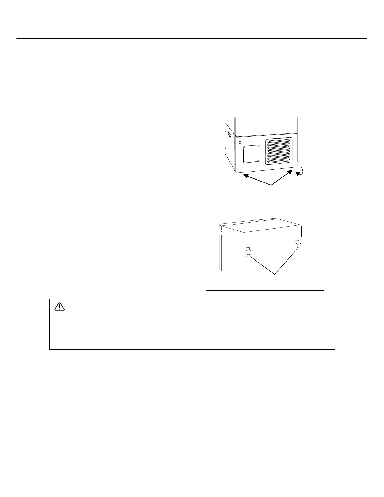
2. Adjust the leveling foot
Extend the leveling feet by rotating them
counterclockwise to contact them to the floor.
Ensure the unit is level. (Fig.1)
3. Fix the unit
Two fixtures are attached to the rear of the frame.
Fix the frame to the wall with these fixtures and rope
or chain. (Fig. 2)
4. Ground (earth)
WARNING
Use a power supply outlet with ground (earth) to prevent electric shock. If the power supply outlet
is not grounded, it is necessary to install a ground by qualified engineers.
Never ground the unit through a gas pipe, water main, telephone line or lightning rod. Such
grounding may cause electric shock in the case of an incomplete circuit.
Fixture
Leveling foot
Fig.1
Fig. 2
Page 49

46
13
START-UP OF UNIT
Follow the procedures for the initial and consequent operations of the unit.
1. Connect the power cord to the dedicated outlet having appropriate rating with the chamber empty, and
turn on the power switch on the freezer.
2. Turn off the switch of the back-up system (optional component) if it is installed.
3. Check that the battery switch is ON.
4. The audible alarm may activated. In this case, press the buzzer stop key (BUZZER) to silence the
alarm.
5. Set the desired chamber temperature. See page 14 for the temperature setting.
6. Check that the chamber temperature reaches the desired temperature.
7. Turn on the switch of back-up system (optional component) if it is installed.
8. Check that the alarm lamp lights and the buzzer sounds by pressing the alarm test key.
9. After confirming the above, you can put articles into the freezer chamber in a small batch to prevent the
temperature rise.
Page 50

47
14
CHAMBER TEMPERATURE SETTING
Table 1 shows the basic procedure for setting the chamber temperature. Perform key operations in the
sequence indicated in the table. The example in the table is based on the assumption that the desired
temperature is -75
o
C.
Note: The unit is set at the factory that the chamber temperature -80
o
C.
Table 1. Basic operation sequence (Example: Chamber temperature -75
o
C)
Description of operation Key operated Indication after operation
1 Turn the power switch ON.
----
The current chamber temperature is
displayed.
2 Press set key. SET
The second digit is flashed.
When pressed, the figure of settable
digit changes.
3
Set to -75 with the numerical value
shift key and digit shift key.
When pressed, the settable digit
is shifted.
4 Press set key. SET
Set temperature is memorized and the
current chamber temperature is
displayed.
Note:
• The temperature set mode returns to the temperature display mode automatically when 90 seconds has
passed without any key operation.
• Although the value of the chamber temperature setting can range from -50
o
C to -90oC, the guaranteed
temperature when there is no load is -85
o
C when the ambient temperature is 30oC.
KEY LOCK FUNCTION
This unit is provided with the key lock function. When the key lock is ON, change of temperature setting
through the key pad is not available. The key lock is set in OFF at the factory.
Display Mode Function
L 0 Key lock is OFF Enable to change of temperature setting
L 1 Key lock is ON Disable to change of temperature setting
Table 2. Procedure for key lock setting (change from key lock OFF to key lock ON)
Description of operation Key operated Indication after operation
1 ----
The current chamber temperature is
displayed.
2 Press digit shift key for 5 seconds.
The first digit is flashed.
3
Press numerical value shift key
and scroll the figure to 1.
When pressed, the figure of settable
digit changes.
4 Press set key. SET
The key lock is set to ON.
The current chamber temperature is
displayed.
Page 51

48
15
ALARM TEMPERATURE SETTING
This unit is provided with the high and low temperature alarm and the temperature at which the alarm is
activated is changeable.
The following procedure shows the setting of alarm temperature according to the condition below:
High temperature alarm: activates at the temperature 5
o
C higher than the set temperature
Low temperature alarm: activates at the temperature 5
o
C lower than the set temperature
Note:
The alarm temperature is set at the factory 10
o
C higher and lower than the set temperature.
The available range of alarm temperature is between 5
o
C and 20oC higher or lower than the set
temperature.
Table 3. Procedure for setting high temperature alarm
Description of operation Key operated Indication after operation
1 ----
The current chamber temperature is
displayed.
2
Press numerical value shift key for
about 5 seconds.
The first digit is flashed.
3
Press numerical value shift key
and scroll the figure to 1.
The first digit is flashed.
4 Press set key. SET The first digit is flashed.
When pressed, the figure of settable
digit changes.
5
Scroll the figure to 005 by using
digit shift key and numerical value
shift key
When pressed, the changeable digit
moves.
6 Press set key. SET
Alarm temperature is memorized and
the current chamber temperature is
displayed.
Table 4. Procedure for setting low temperature alarm
Description of operation Key operated Indication after operation
1 ----
The current chamber temperature is
displayed.
2
Press numerical value shift key for
about 5 seconds.
The first digit is flashed.
3
Press numerical value shift key
and scroll the figure to 2..
The first digit is flashed.
4 Press set key. SET
The first digit is flashed.
When pressed, the figure of settable
digit changes.
5
Scroll the figure to -05 by using
digit shift key and numerical value
shift key
When pressed, the changeable digit
moves.
6 Press set key. SET
Alarm temperature is memorized and
the current chamber temperature is
displayed.
Page 52

49
16
SETTING OF ALARM RESUME TIME
The alarm buzzer is silenced by pressing buzzer stop key (BUZZER) on the control panel during alarm
condition (The remote alarm is not silenced).
The buzzer will be activated again after certain suspension if the alarm condition is continued. The
suspension time can be set by following the procedure shown in the Table 6 below.
The example in the table is based on the assumption that the desired duration is 20 minutes.
Note: The duration is set in 30 minutes at the factory.
Table 6. Setting procedure for alarm resuming time (change from 30 minutes to 20 minutes)
Description of operation Key operated Indication after operation
1 ----
The current chamber temperature is
displayed.
2 Press digit shift key for 5 seconds.
The first digit is flashed.
The settable digit is shifted.
3
Set the figure to F25 with the digit
shift key and numerical value shift
key.
When pressed, the figure of settable
digit changes.
4 Press set key. SET
The current reset time is displayed.
The middle digit is flashed.
5
Set the figure to 020 with the
numerical value shift key.
When pressed, the figure of settable
digit changes.
6 Press set key. SET
The setting is memorized and
the current chamber temperature is
displayed.
• The settable alarm resume time is 10, 20, 30, 40, 50, or 60 minutes (The setting is 010, 020, 030, 040,
050, or 060). The buzzer would not reset if the reset time is set in 000.
• It is recommended to set the alarm resume time when the freezer is not under alarm condition. The
setting during alarm condition is effective on the next alarm condition.
• The setting cannot be changed during power failure.
• The remote alarm during power failure or buzzer and remote alarm during alarm test cannot be
silenced.
• The set mode returns to the temperature display mode automatically when 90 seconds has passed
without any key operation. In this case, any setting before pressing set key (SET) is not memorized.
Page 53

50
17
REMOTE ALARM TERMINAL
The terminal of the remote alarm is installed at the lower left side of the unit. The alarm is outputted
from this terminal. Contact capacity is DC 30 V, 2 A.
Contact output:
between COM. and N.O. between COM. and N.C.
At normal Open Close
At abnormal Close Open
Note:
The alarm is actuated when the power cord is disconnected from the outlet or the power switch is OFF.
REMOTE ALARM
N.C. COM N.O.
MAX DC30V 2A
Page 54

51
18
MONITOR OF FREEZER STATUS
The freezer has a function to monitor the running status of the unit as shown in table 7 below. This is to
notice the running status getting worse (not failure).
1. The status monitor lamp is lit when one of the running status shown in table 7 is detected.
2. The S code (--X, X: 1 to 3) is displayed on the temperature indicator by pressing STATUS key when
the STATUS lamp is lit.
3. Pressing the STATUS key again returns to current chamber temperature on the temperature indicator.
(The indication returns to the chamber temperature display automatically when no key is operated for 90
seconds.)
Table 7. Monitor of running status
Kind of
function
Status Indication
If this status
continues
Remedy
Notice of
abnormal
ambient
temperature
When the ambient
temp. is over approx.
35
o
C or lower than
about 0
o
C.
STATUS lamp
lights.
“--1” is displayed.
Decrease of cooling
performance or
durability of
refrigerating circuit.
Recheck airconditioning of
installed site.
Notice of low
voltage
When the power
source voltage is
less than approx.
195V when the rated
voltage is between
220 and 240V.
STATUS lamp
lights.
“--2” is displayed.
Abnormal heat at
power supply outlet
or degrade of
starting performance
of refrigerating
circuit
Use dedicated
power source.
Notice of
overload
condition
When the running
rate of refrigerating
Circuit is higher than
usual.
STATUS lamp
lights.
“--3” is displayed.
Decrease of cooling
performance or
durability of
refrigerating circuit.
1. This is likely to
happen when a
large amount of
materials is stored.
2. Check ambient
temp., voltage, and
sealing of
outer/inner door.
Note:
• The S code displayed on the temperature indicator is changed every few seconds if two or three status
shown in the above table are detected at the same time. (--1 ⇒ --2 ⇒ --3 ⇒ --1 repeated)
• The monitoring function does not trigger a buzzer or conduct a safety operation.
the case of multiple indication of S code, follow the remedy for each status.
• The status monitor lamp (STATUS) may be lit under normal running condition when the independent
inner door (MDF-7ID or MDF-5ID) is installed because of less cooling performance. In this case, adjust
the air conditioning so that the ambient temperature is around 23
o
C, or set the chamber temperature
10
o
C higher than the current setting.
Page 55

52
19
CHANGE OF COMPRESSOR DELAY TIME
The delay time of high and low stage side compressor can be changed to reduce the load on the power
line and to facilitate the start-up (reset) of the freezer after power failure.
The example in the table is based on the assumption that the delay time is changed to 4 minutes.
(The delay time is set in 2 minutes at the factory.)
Note:
• The delay time should be the same for high stage side and low stage side compressors.
• The setting range for delay time is between 2 and 15 minutes. The cool down of chamber temperature
may be slow when the setting of delay time is over 5 minutes, depending on the installation environment.
There is no need of changing the delay time when the capacity of power source is adequate.
Table 8. Changing procedure for delay time (change from 2 minutes to 4 minutes)
Description of operation Key operated Indication after operation
1 ----
The current chamber temperature is
displayed.
2
Press numerical value shift key for
5 seconds.
The first digit is flashed.
3
Set the figure to F05 with the
numerical value shift key.
When pressed, the figure of settable
digit changes.
4 Press set key. SET
The current delay time is displayed.
The first digit is flashed.
5
Set the figure to 004 with the
numerical value shift key.
When pressed, the figure of the first
digit changes.
6 Press set key. SET
The delay time is memorized and
the current chamber temperature is
displayed.
• The compressor starts to operate with the delay time set by the above procedure at the time of power
on or after power failure. However, the start up of the low stage side compressor is affected by the
chamber temperature and the cascade condenser temperature. The delay time varies depending on
how they meet the start up conditions.
Page 56

53
20
CHANGE OF DOOR ALARM DELAY TIME
The buzzer of door alarm is activated with 2 minutes delay when the door is open. The delay time is
changeable.
Follow the procedure in table 9 below to change the setting of delay time. The procedure assumes that
the delay time is changed from 2 minutes to 3 minutes.
(The delay time is set in 2 minutes at the factory.)
Table 9. Changing procedure for delay time (change from 2 minutes to 3 minutes)
Description of operation Key operated Indication after operation
1 ----
The current chamber temperature is
displayed.
2
Press numerical value shift key for
5 seconds.
The first digit is flashed.
3
Set the figure to F04 with the
numerical value shift key.
When pressed, the figure of settable
digit changes.
4 Press set key. SET
The current delay time is displayed.
The first digit is flashed.
5
Set the figure to 003 with the
numerical value shift key.
When pressed, the figure of the first
digit changes.
6 Press set key. SET
The delay time is memorized and
the current chamber temperature is
displayed.
Note:
• The setting range for delay time is between 1 and 15 minutes.
Page 57

54
21
ALARMS & SAFETY FUNCTIONS
This unit has the alarms and safety functions shown in Table 5, and also self diagnostic functions.
Table 5. Alarms and safety functions
Alarm & Safety Situation Indication Buzzer Safety operation
High temperature
alarm
If the chamber temperature is higher
than the temperature at which the
high temperature alarm is activated.
Low temperature
alarm
If the chamber temperature is lower
than the temperature at which the
low temperature alarm is activated.
ALARM lamp is flashed.
Temperature indicator is
flashed.
Intermittent tone with
15 minutes delay.
Remote alarm with 15
minutes delay.
Power failure alarm
When the power to the unit is
disconnected.
ALARM lamp is flashed. Intermittent tone Remote alarm.
Door alarm When the door is open. Door check lamp lights.
Intermittent tone with
2minutes delay.
-----
Filter check When the condenser filter is clogged. Filter check lamp lights. Intermittent tone -----
Battery check
When about 3 years has passed with
power switch ON.
Battery check lamp lights. ----- -----
Fan motor check
When about 5.5 years has passed with
power switch ON.
Battery check lamp
flashed.
----- -----
Auto-return
When there is no key pressing in
each setting mode for 90 seconds.
Chamber temperature is
displayed.
-----
Finishing of each
setting mode.
Key lock When the key lock is ON. ----- -----
Change of setting is
disable.
If the thermal sensor is disconnected.
ALARM lamp is flashed.
E01 and chamber temp.
are displayed alternately.
Intermittent tone
Remote alarm.
Unit keeps continuous
running.
If the thermal sensor is short-circuited.
ALARM lamp is flashed.
E02 and chamber temp.
are displayed alternately.
Intermittent tone
Remote alarm.
Unit keeps continuous
running.
If the cascade sensor is disconnected.
ALARM lamp is flashed.
E03 and chamber temp.
are displayed alternately.
Intermittent tone Remote alarm.
If the cascade sensor is short
circuited.
ALARM lamp is flashed.
E04 and chamber temp.
are displayed alternately.
Intermittent tone Remote alarm.
If the filter sensor is disconnected.
ALARM lamp is flashed.
E05 and chamber temp.
are displayed alternately.
Intermittent tone Remote alarm.
Sensor abnormality
If the filter sensor is short-circuited.
ALARM lamp is flashed.
E06 and chamber temp.
are displayed alternately.
Intermittent tone Remote alarm.
Battery switch
check
When the battery switch is OFF during
alarm test.
ALARM lamp is flashed.
E09 is flashed.
----- -----
Condenser temp.
abnormality
In the event of failure of fan motor for
cooling the compressor
E10 and chamber temp.
are displayed alternately.
Intermittent tone
Remote alarm.
Compressor of high
stage side stops.
Note:
• When the operation is started in high ambient temperature, the filter check lamp is sometimes flashed.
In this case, the lamp is off automatically when the chamber temperature is getting lower.
• The freezer resumes the operation after power failure with the temperature setting before power failure
as the chamber temperature setting and alarm temperature setting are memorized in the volatile memory.
• The chamber temperature is displayed for 5 seconds by pressing buzzer stop key (BUZZER) during
power failure alarm. Then the buzzer is silenced. The alarm lamp keeps flashing.
Page 58

55
22
ROUTINE MAINTENANCE
WARNING
Always disconnect the power supply to the unit prior to any repair or maintenance of the unit in
order to prevent electric shock or injury.
Ensure you do not inhale or consume medication or aerosols from around the unit at the time of
maintenance. These may be harmful to your health.
Cleaning of cabinet
㩵 Clean the unit once a month. Regular cleaning keeps the unit looking new.
㩵 Use a dry cloth to wipe off small amounts of dirt on the outside and inside of the unit and all
accessories. If the outside panels are dirty, clean them with a diluted neutral dishwashing detergent..
(Undiluted detergent can damage the plastic components. For the dilution, refer to the instruction of the
detergent.)
After the cleaning with the diluted detergent, always wipe it off with a wet cloth. Then wipe off the
cabinet or accessories with a dry cloth.
㩵 Never pour water onto or into the unit. Doing so can damage the electric insulation and cause failure.
㩵 The compressor and other mechanical part are completely sealed. This unit requires absolutely no
lubrication.
㩵 There is a fan behind the compressor, so be very careful if you stick your hand into this part of the unit.
Cleaning of condenser filter
This unit is provided with the filter check lamp on the control panel. Clean the filter when this lamp lights.
Clean the filter once a month even if the check lamp is not on since a clogged filter may cause shorter
compressor life as well as the poor cooling.
Clean the filter by the procedure below.
1. Open the grille by pulling it to you as shown in the
figure.
2. Take out the condenser filter.
3. Wash the filter with water.
4. Replace the filter and the grille.
5. Check that the filter check lamp is off in the event the
check lamp was ON.
WARNING
Do not touch the condenser directly when the filter is removed for cleaning. This may cause injury by
hot surface.
Page 59

56
23
ROUTINE MAINTENANCE
Defrosting of inside wall
The frost is built at the upper portion of the chamber and inner door. The excessive frost possibly make
some gap between the cabinet and door gasket, which may cause poor cooling. Remove the frost on
the inner door with a scraper enclosed with the unit. Following shows the procedure for removing the
chamber frost.
Note: For removing the frost, do not use a tool with sharp edge such as a knife or a screw driver.
1. Turn off the back-up system if applicable.
2. Take out and transfer all the contents to another freezer or a container which is refrigerated by liquid
carbon dioxide or dry ice.
3. Turn off the power switch of the freezer.
4. Open the outer door and inner door. Remove the
inner door by lifting up as shown in the figure.
5. Leave the freezer as it is.
6. The water accumulated on the bottom of the
chamber should be wiped up with a dry cloth.
7. After cleaning the chamber and inner door, replace
the inner door and start up the unit according to the
procedure on page 14.
8. Put back the articles into the sufficiently cooled
freezer compartment.
9. Turn on the back-up system if it is provided.
Page 60

57
24
TROUBLE SHOOTING
If the unit malfunctions, check out the following before calling for service.
Malfunction Check/Remedy
The chamber is not cooled
at all
㩵 The circuit breaker of power source is active.
㩵 The voltage is too low (In this case, call an electrician).
㩵 The power is not supplied.
㩵 The breaker is free.
㩵 The large amount of articles (load) is stored in the chamber at one
time.
The cooling is poor
㩵 The ambient temperature is too high.
㩵 The latch of inner door is not closed completely. The outer door
is not closed firmly. (The frost or ice between the cabinet and door
gasket possibly prevents door seal.)
㩵 The air intake vent is blocked.
㩵 The condenser filter is clogged. Always clean the filter when the
filter check lamp is lit.
㩵 The door is not shut tightly.
㩵 The inner door is not installed correctly.
㩵 The set temperature in the controller is not set properly.
㩵 The grille is blocked out.
㩵 The filter is clogged.
㩵 The freezer is in the direct sunlight.
㩵 There is any heating source near the freezer.
㩵 A rubber cap and insulation are not set correctly.
㩵 You put too many unfrozen articles into the chamber.
Alarm test key cannot
actuate the alarm
㩵 The alarm is activated only when the power switch is ON.
㩵 When only the buzzer or only the alarm is actuated by the alarm test
key, the unactuated part is out of order, and must be replaced.
Note:
If the malfunction is not eliminated after checking the above items, or the malfunction is not shown in the
above table, contact Sanyo sales representative or agent.
Page 61
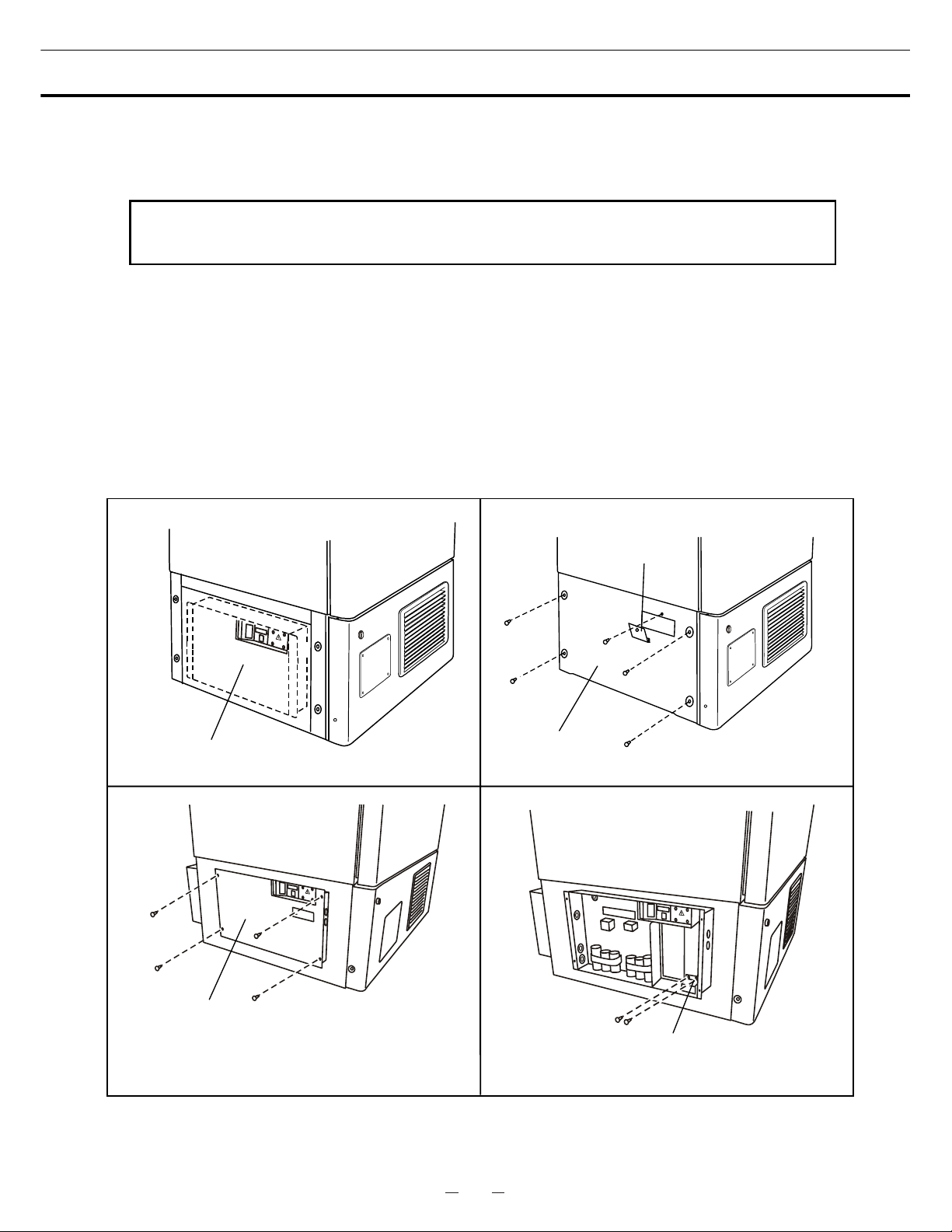
58
25
REPLACEMENT OF BATTERY
Location of a nickel-metal-hydride battery
This unit is provided a nickel-metal-hydride battery for the power failure warning device. The battery is
located in the electrical box inside the cover on the lower left side. (Fig. 1)
The high voltage components are enclosed in the electrical box. The cover should be removed
by a qualified engineer or a service personnel only to prevent the electric shock..
Removal of nickel-metal-hydride battery
1. Turn off the power switch and disconnect the power supply plug.
2. As shown in the Fig. 2, remove 4 screws fixing the side cover with a screw driver and remove the side
cover..
3. Remove 4 screws fixing the electrical box cover with a screw driver. (Fig. 3)
4. Disconnect the battery connector and remove 2 screws fixing the battery mounting plate. (Fig. 4)
5. Take out the battery.
6. Follow the procedure for recycling or proper disposal.
Fig. 4
Battery
mounting plate
Electrical box cover
Fig. 3
Fig. 1
Electrical box
Fig. 2
Switch cover
Side cover
Page 62
59
26
DISPOSAL OF UNIT
WARNING
If the unit is to be stored unused in an unsupervised area for an extended period ensure that children
do not have access and doors cannot be closed completely.
The disposal of the unit should be accomplished by appropriate personnel. Always remove
doors to prevent accidents such as suffocation.
Recycle of battery
The unit contains a rechargeable battery. The battery is recyclable. At the end
of it’s useful life, check with you local solid officials option or proper disposal.
䋪Label indication is obliged to comply with Taiwanese battery regulation.
ᑜ㔚ᳰ㩷
⺧࿁ᡴ㩷
Page 63

60
27
DISPOSAL OF UNIT
Waste Electrical and Electronic Equipment (WEEE) Directive-2002/96/EC
(English)
Your SANYO product is designed and manufactured with high quality materials and components which
can be recycled and reused.
This symbol means that electrical and electronic equipment, at their end-of-life, should be disposed of
separately from your household waste.
Please dispose of this equipment at your local community waste collection/recycling centre.
In the European Union there are separate collection systems for used electrical and electronic products.
Please help us to conserve the environment we live in!
(German)
Ihr SANYO Produkt wurde entworfen und hergestellt mit qualitativ hochwertigen Materialien und
Komponenten, die recycelt und wiederverwendet werden können.
Dieses Symbol bedeutet, daß elektrische und elektronische Geräte am Ende ihrer Nutzungsdauer von
Hausmüll getrennt entsorgt werden sollen.
Bitte entsorgen Sie dieses Gerät bei Ihrer örtlichen kommunalen Sammelstelle oder im Recycling Centre.
In der Europäischen Union gibt es unterschiedliche Sammelsysteme für Elektrik- und Elektronikgeräte.
Helfen Sie uns bitte, die Umwelt zu erhalten, in der wir leben!
Note:
This symbol mark and recycle system are applied only to EU countries
and not applied to the countries in the other area of the world.
Page 64

61
28
DISPOSAL OF UNIT
(French)
Votre produit Sanyo est conçu et fabriqué avec des matèriels et des composants de qualité supérieure qui
peuvent être recyclés et réutilisés.
Ce symbole signifie que les équipements électriques et électroniques en fin de vie doivent être éliminés
séparément des ordures ménagères.
Nous vous prions donc de confier cet équipement à votre centre local de collecte/recyclage.
Dans l’Union Européenne, il existe des systèmes sélectifs de collecte pour les produits électriques et
électroniques usagés.
Aidez-nous à conserver l’environnement dans lequel nous vivons !
Les machines ou appareils électriques et électroniques contiennent fréquemment des matières qui, si
elles sont traitées ou éliminées de manière inappropriée, peuvent s’avérer potentiellement dangereuses
pour la santé humaine et pour l’environnement.
Cependant, ces matières sont nécessaires au bon fonctionnement de votre appareil ou de votre machine.
Pour cette raison, il vous est demandé de ne pas vous débarrasser de votre appareil ou machine usagé
avec vos ordures ménagères.
(Spanish)
Los productos SANYO están diseñados y fabricados con materiales y componentes de alta calidad, que
pueden ser reciclados y reutilizados.
Este símbolo significa que el equipo eléctrico y electrónico, al final de su ciclo de vida, no se debe
desechar con el resto de residuos domésticos.
Por favor, deposite su viejo “televisor” en el punto de recogida de residuos o contacte con su
administración local.
En la Unión Europea existen sistemas de recogida específicos para residuos de aparatos eléctricos y
electrónicos.
Por favor, ayúdenos a conservar el medio ambiente!
Page 65

62
29
DISPOSAL OF UNIT
(Portuguese)
O seu produto SANYO foi concebido e produzido com materiais e componentes de alta qualidade que
podem ser reciclados e reutilizados.
Este símbolo significa que o equipamento eléctrico e electrónico no final da sua vida útil deverá ser
descartado separadamente do seu lixo doméstico.
Por favor, entregue este equipamento no seu ponto local de recolha/reciclagem.
Na União Europeia existem sistemas de recolha separados para produtos eléctricos e electrónicos
usados.
Por favor, ajude-nos a conservar o ambiente em que vivemos!
(Italian)
Il vostro prodotto SANYO è stato costruito da materiali e componenti di alta qualità, che sono riutilizzabili o
riciclabili.
Prodotti elettrici ed elettronici portando questo simbolo alla fine dell’uso devono essere smaltiti
separatamente dai rifiuti casalinghi.
Vi preghiamo di smaltire questo apparecchio al deposito comunale.
Nell’Unione Europea esistono sistemi di raccolta differenziata per prodotti elettrici ed elettronici.
Aiutateci a conservare l’ambiente in cui viviamo!
Page 66

63
30
DISPOSAL OF UNIT
(Dutch)
Sanyo producten zijn ontwikkeld en gefabriceerd uit eerste kwaliteit materialen, de onderdelen kunnen
worden gerecycled en weer worden gebruikt.
Het symbool betekent dat de elektrische en elektronische onderdelen wanneer deze vernietigd gaan
worden , dit separaat gebeurt van het normale huisafval.
Zorg ervoor dat het verwijderen van de apparatuur bij de lokaal erkende instanties gaat gebeuren.
In de Europese Unie wordt de gebruikte elektrische en elektronische apparatuur bij de daarvoor wettelijke
instanties aangeboden.
Alstublieft help allen mee om het milieu te beschermen.
(Swedish)
Din SANYO produkt är designad och tillverkad av material och komponenter med hög kvalitet som kan
återvinnas och återanvändas.
Denna symbol betyder att elektriska och elektroniska produkter, efter slutanvändande, skall sorteras och
lämnas separat från Ditt hushållsavfall.
Vänligen, lämna denna produkt hos Din lokala mottagningstation för avfall/återvinningsstation.
Inom den Europeiska Unionen finns det separata återvinningssystem för begagnade elektriska och
elektroniska produkter.
Vänligen, hjälp oss att bevara miljön vi lever i!
Page 67

64
31
TEMPERATURE RECORDER (OPTION)
An automatic temperature recorders is available for this freezer as the optional component. The type of
the recorder is MTR-G85.
Following shows the attachment procedure.
1. Remove four screws on the front panel and take it off.
By removing four screws, take off the left side panel.
Then take off the cover for the recorder mounting space
by removing four screws. (Fig. 1)
2. As shown in the Fig. 2, insert the temperature
recorder to the mounting space and fix it to the back
side of the front panel by using the recorder fixture
enclosed with the recorder.
3. Take off the recorder sensor cover in the chamber
(bottom left side) by removing two screws. Then
remove the rubber cap and insulation covering the
sensor port. (Fig. 3)
4. As shown in the Fig. 4, pass the recorder sensor
through the sensor guide pipe from the front to the back.
The sensor guide pipe is provided on the upper left side
of the base compartment.
5. Take out the recorder sensor from the guide pipe at
the back side and pass the sensor to the chamber
through the access port. (Fig. 5)
6. Attach the recorder sensor on the sensor cover with
the enclosed clips. Seal the sensor port with a silicon
and replace the recorder sensor cover. Fix the cover
to the inside wall. (Fig. 6)
7. Remove the connector cover. Connect the recorder
connector at the end of the power cord with the white
connector on the left of the base compartment. Bind
the extra lead wire of the sensor with a nylon clip on the
back of the recorder. (Fig. 7)
8. Replace the left side panel and front panel and fix them with screws.
9. Operate the freezer until the chamber temperature gets to the set temperature. Check the recorded
temperature and chamber temperature displayed on the control panel. Adjust the zero adjustment
volume on the temperature recorder so that the recorded temperature can corresponds with the
displayed temperature if they are not compliance each other
Fig. 2
Fig. 3
Fig. 4
Fig. 5
Fig. 6
Fig. 7
connector
Sensor guide pipe
Fig. 1
Recorder
sensor
Silicon
Page 68

65
32
BACK-UP SYSTEM (OPTION)
WARNING
As with any equipment that uses CO
2
gas, there is a likelihood of oxygen depletion in the vicinity
of the equipment. It is important that you assess the work site to endure there is suitable and
sufficient ventilation. If restricted ventilation is suspected, then other methods of ensuring a
safe environment must be considered. These may include atmosphere monitoring and warning
devices.
This freezer can be provided with a back-up system (CVK-UB2) which is available as an optional
component. For the installation, refer to the instruction manual enclosed with the system.
1. Switch of back-up system (BACKUP)
When turning on the system, the lamp is brightened.
This means that the system is ready. To stop the
operation of the system, turn off this switch.
2. Test switch (TEST)
This switch is for checking the operation of back-up
system. Pressing this switch is resulted in the release
of liquid carbon dioxide without system operation.
3. Temperature setting knob (TEMP. SET)
With this knob, set the temperature at which the system
is operated. The effective set temperature range is
between -50
o
C and -70oC.
1
2
3
 Loading...