

Page 1
INSTRUCTION MANUAL
MDF-136
BIOMEDICAL FREEZER
MDF-236
MDF-436
MDF-236
Page 2

Note:
1. No part of this manual may be reproduced in any form without the expressed written
permission of SANYO.
2. The contents of this manual are subject to change without notice.
3. Please contact SANYO if any point in this manual is unclear or if there are any
inaccuracies.
SANYO Electric Biomedical Co., Ltd. All rights reserved. Printed in Japan.
Page 3

CONTENTS
PRECAUTIONS FOR SAFE OPERATION P. 2
CAUTIONS FOR USAGE P. 6
ENVIRONMENTAL CONDITIONS P. 7
FREEZER COMPONENTS P. 8
INSTALLATION P. 11
OPTIONAL COMPONENTS P. 13
START-UP OF UNIT P. 15
REMOTE ALARM TERMINAL P. 15
TEMPERATURE SETTING P. 16
ALARMS & SAFETY FUNCTIONS P. 18
SETTING OF ALARM RESUME TIME P. 19
ROUTINE MAINTENANCE P. 20
TROUBLESHOOTING P. 21
DISPOSAL OF UNIT P. 21
SPECIFICATIONS P. 22
PERFORMANCE P. 23
SAFETY CHECK SHEET P. 24
1
Page 4
PRECAUTIONS FOR SAFE OPERATION
It is imperative that the user complies with this manual as it contains
important safety advice.
Items and procedures are described so that you can use this unit correctly and safely.
If the precautions advised are followed, this will prevent possible injury to the user and
any other person.
Precautions are illustrated in the following way:
WARNING
Failure to observe WARNING signs could result in a hazard to personnel
possibly resulting in serious injury or death.
CAUTION
Failure to observe CAUTION signs could result in injury to personnel and
damage to the unit and associated property.
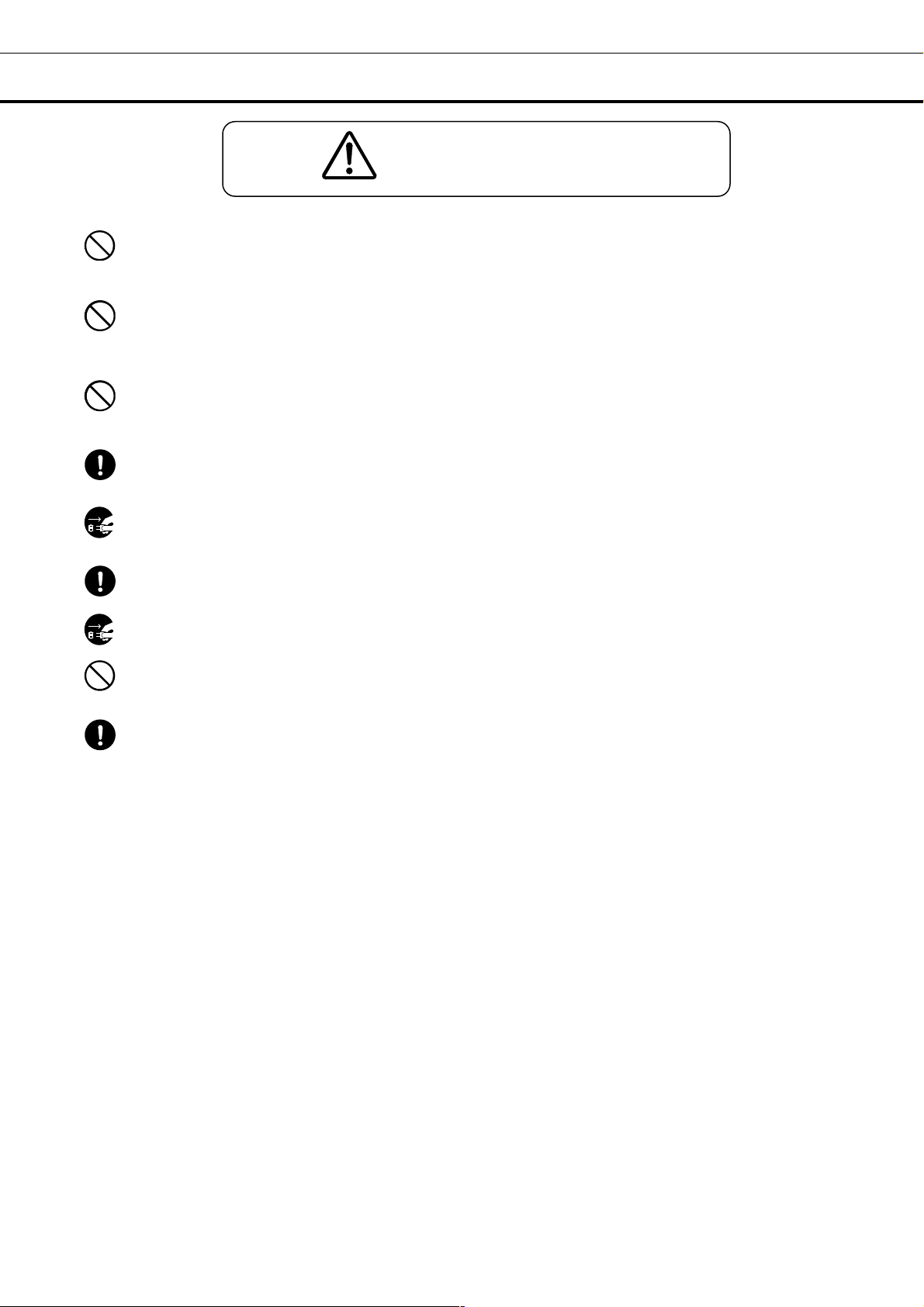
Symbol shows;
this symbol means caution.
this symbol means an action is prohibited.
this symbol means an instruction must be followed.
Be sure to keep this manual in a place accessible to users of this unit.
< Label on the unit >
This mark is labeled on the cover in which the electrical components of high voltage are
enclosed to prevent the electric shock.
The cover should be removed by a qualified engineer or a service personnel only.
2
Page 5
PRECAUTIONS FOR SAFE OPERATION
Do not use the unit outdoors. Current leakage or electric shock may result if the unit is exposed to
rain water.
Only qualified engineers or service personnel should install the unit. The installation by
unqualified personnel may cause electric shock or fire.
Install the unit on a sturdy floor. If the floor is not strong enough or the installation site is not
adequate, this may result in injury from the unit falling or tipping over.
Never install the unit in a humid place or a place where it is likely to be splashed by water.
Deterioration of the insulation may result which could cause current leakage or electric shock.
Never install the unit in a flammable or volatile location. This may cause explosion or fire.
Never install the unit where acid or corrosive gases are present as current leakage or electric
shock may result due to corrosion.
Use a dedicated power source as indicated on the rating label attached to the unit.
Remove dust from the power supply plug before inserting in a power source. A dusty plug or
improper insertion may pose a hazard.
Use a power supply outlet with ground (earth) to prevent electric shock. If the power supply
outlet is not grounded, it will be necessary to install a ground by qualified engineers.
Never ground the unit through a gas pipe, water main, telephone line or lightning rod. Such
grounding may cause electric shock in the case of an incomplete circuit.
Do not insert metal objects such as a pin or a wire into any vent, gap or any outlet for inner air
circulation. This may cause electric shock or injury by accidental contact with moving parts.
Never store volatile or flammable substances in this unit. This may cause explosion or fire.
Never store corrosive substances in this unit. This may lead to damage to the inner components
or electric parts.
Use this unit in safe area when treating the poison, harmful or radiate articles. Improper use
may cause bad effect on your health or environment.
Disconnect the power supply to the unit prior to any repair or maintenance of the unit in order to
prevent electric shock or injury.
Ensure you do not inhale or consume medication or aerosols from around the unit at the time of
maintenance. These may be harmful to your health.
WARNING
3
Page 6
PRECAUTIONS FOR SAFE OPERATION
Never splash water directly onto the unit as this may cause electric shock or short circuit.
Never disassemble, repair, or modify the unit yourself. Any such work carried out by an
unauthorized person may result in fire or injury due to a malfunction.
Disconnect the power supply plug if there is something wrong with the unit. Continued
abnormal operation may cause electric shock or fire.
If the unit is to be stored unused in an unsupervised area for an extended period, ensure that
children do not have access and that doors cannot be closed completely.
The disposal of the unit should be accomplished by appropriate personnel. Remove doors to
prevent accidents such as suffocation.
Prepare a safety check sheet when you request any repair or maintenance for the safety of service
personnel.
Select a level and sturdy floor for installation. This precaution will prevent the unit from tipping.
Improper installation may result in water spillage or injury from the unit tipping over.
Connect the unit to a power source as indicated on the rating label attached to the unit. Use
of any other voltage or frequency other than that on the rating label may cause fire or electric shock.
When removing the plug from the power supply outlet, grip the power supply plug, not the cord.
Pulling the cord may result in electric shock or fire by short circuit.
Never damage or break the power supply plug or cord. Do not use the supply plug if its cord
is loose. This may cause fire or electric shock.
Do not touch any electrical parts such as the power supply plug or any switches with a wet hand.
This may cause electric shock.
Do not put a container with water or heavy articles on the unit. It may cause injury if the articles
fall. Current leakage or electric shock may be resulted form the deterioration of insulation by spilled
water.
WARNING
CAUTION
4
Page 7
PRECAUTIONS FOR SAFE OPERATION
Do not climb onto the unit or do not put articles on the unit. This may cause injury by tipping or
damage to the unit.
Put on dry gloves when you take out refrigerated articles from the freezer. Handing frozen
contents or the inside walls with naked hands may cause frostbite.
Do not defrost inside walls using a knife or ice pick. There are pipelines for cooling behind the
walls. Be careful not to damage the lines as this could cause a breakdown. Also, do not make a
hole in the wall for installation of attachments.
Hold the handle when closing the door. This will reduce the likelihood of a trapped finger.
Disconnect the power supply plug before moving the unit. Take care not to damage the power
cord. A damaged cord may cause electric shock or fire.
Be careful not to tip over the unit during movement to prevent damage or injury.
Disconnect the power plug when the unit is not used for long periods.
Do not put the packing plastic bag within reach of children as suffocation may result
Remove dust and clean the power supply plug periodically. The operation with a dusty plug may
cause fire.
CAUTION
5
Page 8

CAUTIONS FOR USAGE
1. Sometimes the alarm may not operate at the time of first start-up. This does not mean malfunction.
It is due to the complete discharge of incorporated battery. 2-day continuous operation of the freezer is
necessary to charge the battery fully.
2. The digital thermometer of medical freezer is designed to display the temperature of the center part of
the freezing compartment. Although the thermometer sometimes displays a temperature a little bit
higher than the actual temperature of the center part, it gradually approaches the real temperature.
3. An access port to take out the measuring cable in the case is provided on the back wall of the freezer.
Be sure to replace the cap and heat insulator after take out cable or, the inside temperature cannot
complete down, and frost may accumulate outside the port surroundings.
4. Do not use brushes, acids, benzine, thinners, powdered soap. Polishing powders, or hot water for
cleaning, as they can deteriorate the painted surfaces and parts made of plastic and rubber. Be
especially careful not to wipe plastic or rubber parts with volatile solvents such as benzine. Wipe up the
neutral detergents with a wet cloth when used.
5. Frost will accumulate on the inside walls of the freezer during use. Then remove the frost with the
spatula provided or a similar tool. Do not defrost inside walls using a knife or ice pick. There are
pipelines for cooling behind the walls. Be careful not to damage the lines as this could cause a
breakdown. Also, do not make a hole in the wall for installation of attachments.
6. The freezing temperature is different at each position inside the case of this freezer. The set
temperature represents the temperature at the center of the inside case. The refrigerated articles put on
the highest position part, are refrigerated higher than the set temperature, while those put on the lowest
part are refrigerated lower.
7. Do not put too many worm articles into a freezer compartment before enough operating. Put items in
a few at a time after the freezer compartment temperature has cooled to at least -20
8. In the case of high ambient temperature, the cabinet front may heat up after the freezer starts to
operate first. However, this does not denote a malfunction. It is due to heater or hot gas piped around
the unit frame to prevent frost and ice sticking around the cabinet.
o
C.
6
Page 9

ENVIRONMENTAL CONDITIONS
This equipment is designed to be safe at least under the following conditions (based on the IEC 1010-1):
1. Indoor use;
2. Altitude up to 2000 m;
3. Ambient temperature 5
4. Maximum relative humidity 80% for temperature up to 31oC decreasing linearly to 50% relative
humidity at 40oC;
5. Mains supply voltage fluctuations not to exceed ±10% of the nominal voltage;
6. Other supply voltage fluctuations as stated by the manufacturer;
7. Transient overvoltages according to Installation Categories (Overvoltage Categories) II; For mains
supply the minimum and normal category is II;
8. Pollution degree 2 in accordance with IEC 664.
o
C to 40oC
7
Page 10

FREEZER COMPONENTS
6
7
8
12
13
14
1
9 10
MDF-236
52
3
4
11
8
Page 11

FREEZER COMPONENTS
1. Door: To open the door, grip the handle.
2. Handle: Always grip this handle to open and close the outer door.
3. Door gasket: This provides a tight door seal and prevents cold air leak. Keep clean.
4. Access port: This is used for leading the measuring cable from the freezing chamber to the outside.
5. Lock: Turn counterclockwise to 180
6. Control panel: Temperature set key, buzzer key and alarm lamp etc. are installed on the panel.
Digital temperature display is also provided on it. See page 10 for the details.
7. Caster: 4 casters are provided to facilitate moving of the cabinet. At the time of installation, make
sure that the front 2 casters are not contact with the floor, by adjusting the leveling legs.
8. Leveling foot: 2 feet are provided on the front side (right and left). Keep the unit in level by
adjusting these legs at the installation.
9. Space for temperature recorder: An automatic temperature recorder (optional part) can be
attached here. See page 13 “Temperature recorder”.
10. Drain port: The water accumulated on the bottom of the chamber can be drained through this port.
11. Basket: Used for storing the materials in the chamber.
12. Remote alarm terminal (on back side): This is used to notice an alarm condition of the unit to
remote location. Refer to page 15 “Remote alarm terminal”.
13. Battery switch: This is a switch for power failure. Always set the switch in ON position. Be sure
to turn off this switch to save the battery if the freezer is not in operating for the long period (more than 1
month).
14. Power switch: This is for turning ON/OFF the power to the unit. ON – “I” OFF – “○”. This has
a function as an over-current protection breaker (15A).
o
with a key and the outer door is securely locked.
9
Page 12

FREEZER COMPONENTS
Control panel and keypad
1. Alarm test key (ALARM TEST): Test key for alarm device. By pressing this key, the alarm lamp is
flashed, remote alarm is activated and buzzer sound. This means all alarm function operate correctly.
2. Buzzer stop key (BUZZER): To silence the audible alarm, press this key. The remote alarm is also
silenced by pressing this key. (The buzzer cannot be stopped during remote alarm testing.)
3. Defrost key (DEF): By pressing this key for 5 seconds, the refrigerating operation is stopped.
Pressing this key again after defrosting leads resumption of the operation.
Note: The refrigerating operation never resume automatically after defrosting.
4. Set key (SET): Temperature setting mode is led by pressing this key. Once the key is pressed, the
changeable digit is flashed. Pressing this key again after setting desired temperature, the setting is
stored into computer memory. If there is no key operation for 90 seconds during the temperature setting
mode, the temperature setting mode is invalid automatically. See page 16 for the details.
5. Digit shift key ( ): Pressing this key in the setting mode causes the changeable digit to shift. Key
lock is available by pressing this key for more than 5 seconds in the temperature display mode. Refer to
page 16 for the key lock.
6. Numerical value shift key ( ): Pressing this key in the setting mode causes the numerical value to
shift. “ON-OFF” of key lock can be selected by pressing this key in the key lock mode.
7. Alarm lamp (ALARM): This lamp is flashed when the audible alarm is activated.
8. Digital temperature indicator: This indicator shows the present chamber temperature or set
temperature.
1 2 3 4 5 6
7 8
10
Page 13

INSTALLATION
Installation site
To operate this unit properly and to obtain maximum performance, install the unit in a location with the
following conditions:
1. A location not subjected to direct sunlight
Installation in a location subjected to direct sunlight may lead to inadequate cooling.
2. A location with adequate ventilation
Leave at least 10 cm around the unit for ventilation. Poor ventilation will result in a reduction of the
refrigeration capacity.
3. A location away from heat generating sources
Avoid installing the unit near heat-emitting appliances such as gas ranges or stoves. Heat can cause
inefficient refrigeration.
4. A location with a sturdy and level floor
WARNING
Install the unit on a sturdy floor. If the floor is not strong enough or the installation site is not
adequate, this may result in injury from the unit falling or tipping over.
Select a level and sturdy floor for installation. This precaution will prevent the unit from tipping.
Improper installation may result in water spillage or injury from the unit tipping over.
5. A location without flammable or corrosive gas
WARNING
Never install the unit in a flammable or volatile location. This may cause explosion or fire.
Never install the unit where acid or corrosive gases are present as current leakage or electric shock
may result due to corrosion.
6. A location not prone to high humidity
WARNING
Do not use the unit outdoors. Current leakage or electric shock may result if the unit is exposed to
rain water.
Never install the unit in a humid place or a place where it is likely to be splashed by water.
Deterioration of the insulation may result which could cause current leakage or electric shock.
11
Page 14

INSTALLATION
Installation
1. Remove the packaging materials and tapes
Remove all transportation packaging materials and tapes. Open the doors and ventilate the unit. If the
outside panels are dirty, clean them with a neutral detergent and wipe it up with a wet cloth.
2. Adjust the leveling feet
Extend the leveling feet by rotating them
counterclockwise to contact them to the floor.
Ensure the unit is level.
3. Fix the unit
Two fixtures are attached to the rear of the frame.
Fix the frame to the wall with these fixtures and rope
or chain.
4. Ground (earth)
Leveling foot
WARNING
Use a power supply outlet with ground (earth) to prevent electric shock. If the power supply outlet is
not grounded, it is necessary to install a ground by qualified engineers.
Never ground the unit through a gas pipe, water main, telephone line or lightning rod. Such
grounding may cause electric shock in the case of an incomplete circuit.
12
Page 15

OPTIONAL COMPONENTS
Temperature recorder
WARNING
Always disconnect the power supply to the unit prior to attachment of a temperature recorder in
order to prevent electric shock or injury.
An automatic temperature recorders is available for this freezer as the optional component. The type of
the recorder is MTR-G85. For the attachment, the mounting kit (MDF-S740) is necessary.
Following shows the attachment procedure.
1. Remove four screws on the cover for the recorder
mounting space and take off the cover. (Fig. 1)
2. Fix temperature recorder to the mounting by using 2
screws and fixture enclosed with the mounting kit.
(Fig. 2)
3. Connect the power cord of the recorder with the
coupler in the unit compartment of the freezer.
4. Remove the caps and insulation covering the access
port on the chamber side and unit compartment side.
(Fig. 3)
Then pass the recorder sensor through this port to go
into the freezer chamber.
5. Insert the recorder sensor into the tube enclosed with
the mounting kit.
Cap
Door
Chamber
Insulation
Front view
Fixture
Fig. 1
Fig.2
Fig. 3
13
Page 16

OPTIONAL COMPONENTS
6. As shown in the Fig. 4, fix the recorder sensor on the
chamber wall by using 2 clips with a 10mm spacer
located between the wall and the clip. The clips and
spacers are enclosed with the mounting kit.
7. Cover the gap of the access port on the chamber
side completely by a silicon sealant after pushing the
insulation into the gap.
8. After binding the lead wire on the back of the
recorder and fix the recorder to the freezer with 4
screws removed in procedure 1. (Fig. 5)
Spacer
Clip
Sensor
Fig. 4
Fig. 5
14
Page 17

START-UP OF UNIT
Follow the procedures for the initial and consequent operations of the unit.
1. Turn the power switch ON with the chamber empty.
2. Turn ON the battery switch.
3. The alarm sometimes may operate. In this case, silence the alarm by pressing BUZZER key.
4. Set the chamber temperature to a desired value.
5. Allow the unit to achieve the desired chamber temperature.
6. Check that the alarm lamp is flashed and the buzzer is activated by pressing ALARM TEST key. The
remote alarm is also operated. E09 is displayed on the control panel if the battery switch is OFF. Make
sure to turn on the battery switch.
7. Now you can put articles into the freezer chamber gradually to minimize the temperature rise.
REMOTE ALARM TERMINAL
WARNING
Always disconnect the power supply cord before connecting an alarm device to the remote alarm
terminal.
The terminal of the remote alarm is installed at the back
of the unit. The alarm is outputted from this terminal.
Contact capacity is DC 30V, 2 A.
Contact output: At normal condition “Open”
At abnormal condition “Close”
Note:
The remote alarm is silenced by pressing the BUZZER
key as the remote alarm is operated in conjunction with
the buzzer except for the power failure alarm and alarm
test.
The contact is closed in the case of power failure.
Terminal
15
Page 18

TEMPERATURE SETTING
Chamber temperature
Table 1 shows the basic procedure for setting the chamber temperature. Perform key operations in the
sequence indicated in the table. The example in the table is based on the assumption that the desired
temperature is -35
Note: The unit is set at the factory that the chamber temperature -30oC.
Table 1. Basic operation sequence (Example: Chamber temperature -35oC)
Description of operation Key operated Indication after operation
1 Switch ON the freezer. ----
2 Press SET key. SET
3 Press key.
Press key and scroll the figure
4
to 5.
5 Press SET key. SET
Note:
The temperature set mode returns to the temperature display mode automatically when 90 seconds has
passed without any key operation.
Although the value of the chamber temperature setting can range between -18
guaranteed temperature without load is -35
o
C.
The current chamber temperature is
displayed.
The second digit is flashed.
When pressed, the settable
digit moves.
When pressed, the figure of settable
digit increases.
Set temperature is memorized and the
current chamber temperature is
displayed.
o
C at ambient temperature of 35oC.
o
C and -40oC, the
Key lock function
This unit is provided with the key lock function. When the key lock is ON, change of temperature setting
through the key pad is not available. The key lock is set in OFF at the factory.
Display Mode Function
Key lock is OFF Enable to change of temperature setting
Key lock is ON Disable to change of temperature setting
Table 2. Procedure for key lock setting (change from key lock OFF to key lock ON)
Description of operation Key operated Indication after operation
---- The current chamber temperature is
1
2 Press key for 5 seconds.
Press key and scroll the figure
4
to 1.
5 Press SET key. SET
The right digit is flashed.
When pressed, the figure of settable
displayed.
digit increases.
The key lock is set to ON.
The current chamber temperature is
displayed.
16
Page 19

TEMPERATURE SETTING
Alarm temperature setting
This unit is provided with both high and low temperature alarms. The temperature at which the alarm is
activated may be changed.
The available set range for high temperature alarm is between +5
low temperature alarm against the chamber temperature.
Note: The temperature alarm is set at 10
Display Mode Function
High temperature alarm set See Table 5 on page 18
Low temperature alarm set See Table 5 on page 18
As an example, Table 3 shows the procedure to set the high temperature alarm so that the alarm can
activate when the chamber temperature is 5oC higher than the set temperature.
Table 4 shows the procedure to set the low temperature alarm so that the alarm can activate when the
chamber temperature is 5
Table 3. Procedure for setting high temperature alarm
Description of operation Key operated Indication after operation
1
2 Press key for 5 seconds.
Press key and scroll the figure
3
to 1.
4 Press SET key. SET
Set the temperature to 005 with the
5
key and key.
6 Press SET key. SET
o
C lower than the set temperature.
o
C of the set temperature at the factory.
---- The current chamber temperature is
displayed.
The first digit is flashed.
When pressed, the figure of settable
digit increases.
The right digit is flashed.
Pressing the key shifts the digit which can be set.
When pressed, the figure of settable
digit increases.
Alarm temperature is memorized and
the current chamber temperature is
displayed.
o
C and +15oC, and -5oC and -15oC for
Table 4. Procedure for setting low temperature alarm
Description of operation Key operated Indication after operation
1
2 Press key for 5 seconds.
Press key and scroll the figure
3
to 2.
4 Press SET key. SET
Set the temperature to -05 with the
5
key and key.
6 Press SET key. SET
---- The current chamber temperature is
displayed.
The right digit is flashed.
When pressed, the figure of settable
digit increases.
The right digit is flashed.
Pressing the key shifts the digit which can be set.
When pressed, the figure of settable
digit increases.
Alarm temperature is memorized and
the current chamber temperature is
displayed.
17
Page 20

ALARMS & SAFETY FUNCTIONS
This unit has the alarms and safety functions shown in Table 5, and also self diagnostic functions.
Table 5 Alarms and safety functions
Alarm & Safety Situation Indication Buzzer Safety operation
High temperature
alarm
Low temperature
alarm
Power failure alarm
Auto-return
Key lock When the key lock is “ON”. ----- -----
Thermal sensor
abnormality
Thermal sensor
abnormality
(MDF-436 only)
Battery switch
check
Compressor temp.
abnormality
(MDF-436 only)
If the chamber temperature is higher
than the temperature at which the
high temperature alarm is activated.
If the chamber temperature is lower
than the temperature at which the
low temperature alarm is activated.
In the case of power failure.
When power switch is turned OFF.
When the power to the unit is
disconnected.
When there is no key pressing in
each setting mode for 90 seconds.
If the thermal sensor is disconnected.
If the thermal sensor is short-circuited.
If the protective sensor for compressor
is disconnected.
If the protective sensor for compressor
is short-circuited.
When the battery switch is OFF at the
time of alarm test.
In the case of failure of compressor
cooling fan motor.
In the case of abnormal high
temperature due to the dust on the
condenser.
In the case of abnormal high ambient
temperature.
Note:
1. The above power failure alarm is available when the battery switch is ON and the battery is charged.
If the battery switch is OFF or the battery is discharged, only the remote alarm is activated.
2. The power failure alarm can be kept about 12 hours with the battery charged completely. 2-day
operation of the freezer is needed to charge the battery full.
3. The chamber temperature is displayed for 5 seconds if the BUZZER key is depressed during the power
failure alarm. After that, the alarm stops and the alarm lamp blinks.
4. The remote alarm is silenced by pressing BUZZER key as the remote alarm is operated in conjunction
with the buzzer, except for the power failure alarm.
5. After power failure, the operation is resumed with the condition before power failure since the
temperature setting and alarm temperature setting are memorized in a nonvolatile memory.
ALARM lamp is flashed.
Temperature indicator is
flashed.
ALARM lamp is flashed.
Temperature indicator is
flashed.
ALARM lamp is flashed. Intermittent tone Remote alarm.
Chamber temperature is
displayed.
ALARM lamp is flashed.
E01 and chamber temp. are
displayed alternately.
ALARM lamp is flashed.
E02 and chamber temp. are
displayed alternately.
ALARM lamp is flashed.
E03 and chamber temp. are
displayed alternately.
ALARM lamp is flashed.
E04 and chamber temp. are
displayed alternately.
E09 is flashed. Intermittent tone Remote alarm.
E10 is flashed. Intermittent tone
Intermittent tone with
15 minutes delay.
Intermittent tone with
15 minutes delay.
Intermittent tone
Intermittent tone
Intermittent tone
Intermittent tone
-----
Remote alarm with 15
minutes delay.
Remote alarm with 15
minutes delay.
Finishing of each
Setting mode.
Change of setting is
disable.
Remote alarm.
Continuous running.
Remote alarm.
Continuous running.
Remote alarm.
Normal operation.
Remote alarm.
Normal operation.
Remote alarm.
Compressor stops
running.
18
Page 21

SETTING OF ALARM RESUME TIME
The alarm buzzer and remote alarm are silenced by pressing BUZZER key on the control panel during
alarm condition. The buzzer and remote alarm will be activated again after certain suspension if the
alarm condition is continued. The suspension time can be set by following the procedure shown in the
Table 6 below.
The example in the table is based on the assumption that the desired duration is 20 minutes.
Note: The duration is set in 30 minutes at the factory.
Table 6. Setting procedure for alarm resuming time (change from 30 minutes to 20 minutes)
Description of operation Key operated Indication after operation
1 ----
2 Press key for 5 seconds.
Set the figure to F25 with the
3
key and key.
4 Press SET key. SET
Set the figure to 020 with the
5
key.
6 Press SET key. SET
• The settable alarm resume time are 10, 20, 30, 40, 50, or 60 minutes. The buzzer and remote alarm
would not reset if the reset time is set in 000.
• The setting of alarm reset time cannot be changed during the defrosting.
• The buzzer and remote alarm during power failure or alarm testing cannot be silenced.
• The set mode returns to the temperature display mode automatically when 90 seconds has passed
without any key operation. In this case, any setting before pressing SET key is not memorized.
The first digit is flashed.
When pressed, the figure of settable
The current chamber temperature is
displayed.
Pressing the key shifts the digit which can be set.
digit increases.
The current reset time is displayed.
The middle digit is flashed.
When pressed, the figure of settable
digit increases.
Alarm temperature is memorized and
the current chamber temperature is
displayed.
19
Page 22

ROUTINE MAINTENANCE
WARNING
Always disconnect the power supply to the unit prior to any repair or maintenance of the unit in
order to prevent electric shock or injury.
Ensure you do not inhale or consume medication or aerosols from around the unit at the time of
maintenance. These may be harmful to your health.
CAUTION
Always put on the dry gloves to protect the hands at the time of maintenance. No gloves may cause
cut of the finger by the edge or corner.
Cleaning of cabinet
1. Clean the unit once a month. Regular cleaning keeps the unit looking new.
2. Use a dry cloth to wipe off small amounts of dirt on the outside and inside of the unit and all
accessories. If the unit is very dirty, use a neutral detergent.
3. After cleaning, wipe away the cleaner completely with a cloth washed in clean water.
4. Never pour water onto or into the unit. Doing so can damage the electric insulation and cause failure.
・The compressor and other mechanical parts are completely sealed. This unit requires absolutely no
lubrication.
・Remove dust from the power supply plug periodically.
Defrosting
This freezer is direct-cooling type and the frost is built on the chamber wall during long term operation.
The excessive frost possibly make some gap between the cabinet and door gasket, which may cause
poor cooling. Remove the frost inside the chamber once a month. Following shows the procedure for
removing the chamber frost.
1. Temporarily move all the contents of freezer chamber to another freezer.
2. Press DEF key for 5 seconds to stop the refrigerating operation. While the refrigerating operation is
stopped, the current chamber temperature and dF is displayed on the control panel alternatively.
3. After a several hours, check visually that all defrost was removed completely.
4. Remove the cap of drain port on the bottom of the chamber and drain the accumulated water.
5. Wipe up the water remaining in the freezer chamber and then replace the cap of drain port.
6. Press DEF key so that the refrigerating operation can be started.
7. Once the chamber temperature has dropped to the desired temperature, place the original contents
back in the freezer chamber.
Note:
After the defrosting, the refrigerating operation is never resumed automatically. Make sure to press DEF
key to start the freezer operation after defrosting.
While the freezer stops refrigerating operation for defrosting, neither high temperature alarm nor low
temperature alarm is effective.
20
Page 23

TROUBLE SHOOTING
If the unit malfunctions, check out the following before calling for service.
The chamber is not cooled at all
1. The circuit breaker of power source is active.
2. The voltage is too low. (In this case, call an electrician.)
3. The power switch is not ON.
4. The large amount of articles (load) is stored in the chamber at one time.
5. The freezer is in defrost condition.
The cooling is poor
1. The ambient temperature is too high.
2. The door is not closed firmly.
3. The large amount of frost is built on the chamber wall.
4. The air intake vent is blocked.
5. The set temperature is not inputted properly.
6. The freezer is in the direct sunlight.
7. There is any heating source near the freezer.
8. A rubber cap and insulation for the access port are not set correctly.
9. You put too many unfrozen articles into the freezer compartment.
When the unit does not accept changes of set-point temperature
1. The key lock is set in “ON” mode.
Noise
1. The freezer is not installed on the sturdy floor.
2. The freezer is not leveled with the leveling feet.
3. There is anything touching the frame.
4. The freezer is in the status immediately after start up.
The unit sometimes causes a noise when the chamber temperature is high due to the large load. The
noise gets less and less accompanying with the cooling of the chamber.
DISPOSAL OF UNIT
WARNING
If the unit is to be stored unused in an unsupervised area for an extended period ensure that children
do not have access and doors cannot be closed completely.
The disposal of the unit should be accomplished by appropriate personnel. Always remove
doors to prevent accidents such as suffocation.
21
Page 24

SPECIFICATIONS
Name Biomedical Freezer
Model MDF-136 MDF-236 MDF-436
External dimensions W640 x D687 x H881 (mm) W905 x D687 x H881 (mm) W1265 x D807 x H905 (mm)
Internal dimensions W525 x D440 x H715 (mm) W790 x D440 x H715 (mm) W1140 x D550 x H735 (mm)
Effective capacity 138 L 221 L 426 L
Exterior Polyester finish baked on zinc galvanized steel
Interior Colored aluminum plate
Door Polyester finish baked on zinc galvanized steel
Insulation Rigid polyurethane foamed-in place (CFC-FREE)
Baskets Polyethylene coated steel wire
Access port Diameter 17 mm, Right side and bottom left
Compressor Hermetic type, 175 W Hermetic type, 350 W
Condenser Wire and tube type
Evaporator Aluminum tube on sheet type
Refrigerant R-404A
Temperature controller Electronics controller (between -18 and -40oC)
Temperature display Digital display (between -50 and +50oC)
Temperature sensor Thermister sensor
Temperature alarm Flash of digital indicator and alarm lamp, Buzzer, (Remote alarm)
Accessories Key 1 set, Scraper 1, Basket 2 (MDF-136), 3 (MDF-236), 4 (MDF-436)
Weight 45 kg 54 kg 71 kg
Battery
Optional component
Note:Design or specifications will be subject to change without notice.
For power failure alarm, Nickel hydrogen battery, DC 6V, 1100mAh, Automatic charge
Mounting kit for automatic temperature recorder (MDF-S740)
Fin & tube + wire & tube type
Fan motor 2W
Automatic temperature recorder (MTR-G85)
Baskets
22
Page 25

PERFORMANCE
MDF-136
Cooling performance -35
Temperature control range -20oC to -35oC
Rated voltage AC 110 V AC 115 V AC 220 V AC 220 to 240 V
Rated frequency 60 Hz 60 Hz 60 Hz 50 Hz
Rated power consumption 140 W 140 W 150 W 145 W
Noise level 37 dB [A] (background noise; 20 dB)
Maximum pressure 2570 kPa
MDF-236
Cooling performance -35
Temperature control range -20oC to -35oC
Rated voltage AC 110 V AC 115 V AC 220 V AC 220 to 240 V
Rated frequency 60 Hz 60 Hz 60 Hz 50 Hz
Rated power consumption 140 W 140 W 170 W 160 W
Noise level 36 dB [A] (background noise; 20 dB)
Maximum pressure 2260 kPa
MDF-436
Cooling performance -35
Temperature control range -20oC to -35oC
Rated voltage AC 110 V AC 115 V AC 220 V AC 220 to 240 V
Rated frequency 60 Hz 60 Hz 60 Hz 50 Hz
Rated power consumption 230 W 230 W 220 W 220 W
Noise level 40 dB [A] (background noise; 20 dB)
Maximum pressure 2180 kPa
Note :The unit with CE mark complies with EC directives 89/336/EEC, 93/68/EEC and 73/23/EEC.
o
C (ambient temperature; 35oC, no load)
o
C (ambient temperature; 35oC, no load)
o
C (ambient temperature; 35oC, no load)
23
Page 26

CAUTION
Please fill in this form before servicing.
Hand over this form to the service engineer to keep for his and your safety.
Safety check sheet
1. Refrigerator contents :
Risk of infection:
Risk of toxicity:
Risk from radioactive sources:
(List all potentially hazardous materials that have been stored in this unit.)
Notes :
2.
Contamination of the unit
Unit interior
No contamination
Decontaminated
Contaminated
Others:
3. Instructions for safe repair/maintenance of the unit
a) The unit is safe to work on
b) There is some danger (see below)
Procedure to be adhered to in order to reduce safety risk indicated in b) below.
Date :
Signature :
Address, Division :
Telephone :
□Yes □No
□Yes □No
□Yes □No
□Yes □No
□Yes □No
□Yes □No
□Yes □No
□Yes □No
□Yes □No
□Yes □No
Product name :
Biomedical Freezer
Please decontaminate the unit yourself before calling the service engineer.
Model :
MDF-136/236/436
Serial number : Date of Installation :
24
Page 27

7FB6P101279004
Recycled paper
CEM
SANYO Electric Biomedical Co., Ltd.
5-5, Keihan-Hondori 2-Chome
Moriguchi City, Osaka 570-8677 Japan
Printed in Japan
 Loading...