

SANYO LC7535M Datasheet

Overview
The LC7535M is an electronic volume and loudness
control IC that provides volume, balance, and loudness
functions with a minimal number of external components
and that can be controlled electronically.
Functions
• Volume: Provides 81 positions from 0 dB to –79 dB in
1-dB steps and –∞. A balance function can be
implemented by controlling the left and right volume
levels independently.
• Loudness: A loudness function can be implemented by
attaching external capacitors at the output tap provided
at the –20-dB position in the 5-dB step volume control.
• S (select) pin: Up to two LC7535M chips can be used on
the same bus.
• Serial data input: The LC7535M supports
communication with the controller in the CCB format.
Feature
• High voltage-handling capacity: ±16 V.
Package Dimensions
unit: mm
3216A-MFP30S
CMOS IC
53098RM (OT) No. 5760-1/9
SANYO: MFP30S
[LC7535M]
SANYO Electric Co.,Ltd. Semiconductor Bussiness Headquarters
TOKYO OFFICE Tokyo Bldg., 1-10, 1 Chome, Ueno, Taito-ku, TOKYO, 110-8534 JAPAN
Electronic Volume/Loudness Control with Serial Data
Control and High Voltage-Handling Capacity
LC7535M
Ordering number : EN5760
• CCB is a trademark of SANYO ELECTRIC CO., LTD.
• CCB is SANYO’s original bus format and all the bus
addresses are controlled by SANYO.
Parameter Symbol Conditions Ratings Unit
V
DD
max VEE≤ VSS< VCC< V
DD
VSSto VSS+ 18 V
Maximum supply voltage V
EE
max VEE≤ VSS< VCC< V
DD
VSS– 18 to V
SS
V
V
CC
max VEE≤ VSS< VCC< V
DD
VSSto VSS+ 7 V
V
IN
max1 CL, DI, CE 0 to VCC+ 0.3 V
Maximum input voltage V
IN
max2 L5dBIN, R5dBIN, L1dBIN, R1dBIN VEE– 0.3 to VDD+ 0.3 V
V
IN
max3 S VCC– 0.3 to VDD+ 0.3 V
Allowable power dissipation Pd max Ta ≤ 75°C 250 mW
Operating temperature Topr –30 to +75 °C
Storage temperature Tstg –40 to +125 °C
Specifications
Absolute Maximum Ratings at Ta = 25°C, VSS= 0 V
Parameter Symbol Conditions
Ratings
Unit
min typ max
V
DDVDD
VCC+ 4.5 16 V
Supply voltage V
EE
V
EE
–16 0 V
V
CCVCC
4.5 5 5.5 V
Input high-level voltage
V
IH
1 CL, DI, CE 0.8 V
CC
V
CC
V
V
IH
2 S 0.8 × (VDD– VCC) + V
CC
V
DD
V
Input low-level voltage
V
IL
1 CL, DI, CE V
SS
0.2 V
CC
V
V
IL
2S V
CC
0.2 × (VDD– VCC) + V
CC
V
Allowable Operating Ranges at Ta = 25°C, VSS= 0 V
Continued on next page.
No. 5760-2/9
LC7535M
Continued from preceding page.
Parameter Symbol Conditions
Ratings
Unit
min typ max
Input voltage amplitude V
IN
L5dBIN, R5dBIN, L1dBIN, R1dBIN V
EE
V
DD
Vp-p
Input pulse width t
øw
CL 1 µs
Setup time t
set up
CL, DI, CE 1 µs
Hold time t
hold
CL, DI, CE 1 µs
Operating frequency t
opg
CL 500 kHz
Parameter Symbol Conditions
Ratings
Unit
min typ max
Total harmonic distortion THD
V
IN
= 1 Vrms, f = 1 kHz,
0.002 %
With all tone control settings flat, V
DD
– VEE= 30 V
V
IN
= 1 Vrms, f = 1 kHz,
Crosstalk C
T
With all tone control settings flat, RG = 1 kΩ, 70 dB
V
DD
– VEE= 30 V
Output at maximum attenuation V
Omin
VIN= 1 V rms, f = 1 kHz, with the volume set at –∞,
–95 dB
V
DD
– VEE= 30 V
Output noise voltage V
N
With all tone control settings flat, Rg = 1 kΩ
2 10 µV
IHF-A, V
DD
– VEE= 30 V
Total resistance
Rvol1 5-dB volume control block 75 kΩ
Rvol2 1-dB volume control block 20 kΩ
L5dBIN, R5dBIN, LCT1, RCT1, LCT2, RCT2, L5dBOUT,
Output off leakage current I
OFF
R5dBOUT, L1dBIN, R1dBIN, L1dBOUT, R1dBOUT, LVM, –10 +10 µA
RVM
Input high-level current I
IH
CL, DI, CE : VIN= V
CC
10 µA
Input low-level current I
IL
CL, DI, CE : VIN= V
SS
–10 µA
Current drain
I
DD
VDD= 16 V 1 mA
I
CC
VCC= 5.5 V 1 mA
Electrical Characteristics at Ta = 25°C, VSS= 0 V
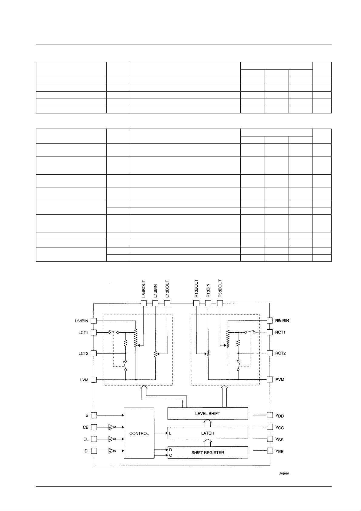
Equivalent Circuit

Sample Application Circuit
No. 5760-3/9
LC7535M
Test Circuit
Total Harmonic Distortion
With an identical circuit for the right channel
 Loading...