

SANYO LA4601 Datasheet
Ordering number : EN6013
LA4601
Monolithic Linear IC
LA4601
Audio Power Amplifier for
Radio Cassette Recorders
Overview
This is a different-package version of the power
amplifier LA4600 with ultralow peripheral
component count. Basic power supply spec is Vcc
= 15V, but a 9V spec for operation without
heatsink is also possible. BS capacitor, NF
capacitor, and oscillation-stopping CR components
are incorporated into the IC circuitry .
Functions
• Pin compatible with the LA4600
• Heatsink not required for 9V version
• Output power VCC =15V/3Ω....7.0W X 2
• Built-in stanby switching
• Built-in overheat protection (TSD)
Specifications
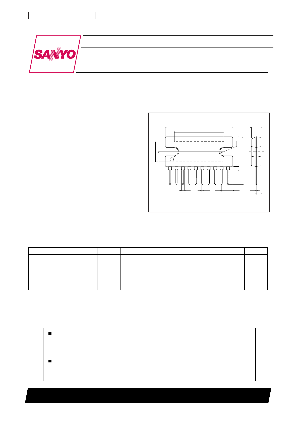
Package Dimensions
unit: mm
3024-SIP10H
[LA4601]
27.0
20.0
8.4
7.0
1.4
0.5
101
2.54
SANYO : SIP10H
2.07
R1.7
11.8
1.0min
13.2max
6.0
0.4
4.0
2.0
Maximum Ratings at Ta = 25°C
Parameter Symbol Conditions Ratings Unit
Maximum supply voltage Vcc
Allowable power dissipation Pd max With an arbitrary large heatsink 25.0 W
Thermal resistance
Operating temperature Topr °C
Storage temperature Tstg °C
Any and all SANYO products described or contained herein do not have specifications that can handle
applications that require extremely high levels of reliability, such as life-support systems, aircraft's
control systems, or other applications whose failure can be reasonably expected to result in serious
physical and/or material damage. Consult with your SANYO representative nearest you before using
any SANYO products described or contained herein in such applications.
SANYO assumes no responsibility for equipment failures that result from using products at values that
exceed, even momentarily, rated values (such as maximum ratings, operating condition ranges, or other
parameters) listed in products specifications of any and all SANYO products described or contained
herein.
max Rg=0 (No signal) 24 V
θ j-c
– 40 to +150
3.0 °C/W
– 20 to +75
SANYO Electric Co., Ltd. Semiconductor Business Headquarters
TOKYO OFFICE Tokyo Bldg., 1-10, 1 Chome, Ueno, Taito-ku, TOKYO, 110-8534 JAPAN
N1298RM(KI)
No. 6013-1/7
LA4601
Operating Conditions at Ta = 25°C
Parameter Symbol Conditions Ratings Unit
Recommended supply voltage
Recommended load resistance
Operating supply voltage range
Operating load resistance range Ω
V
cc
R
L
Vcc op
Within maximum ratings V
Electrical Characteristics at Ta = 25°C, VCC = 15V, RL = 3Ω , f = 1 kHz
15 V
3 Ω
5.0 to 22
2.7 to 8
Parameter
Standby current Ist Standby pin -> GND 1.0 10
Quiescent current Icco R g= 0 20 35 70 m A
Voltage gain VG Vo=0 dBm 43.0 45.0 47.0 dB
Total harmonic distortion THD Po=1w 0.2 0.8 %
Output noise voltage Vno Rg=0, DIN AUDIO 0.15 0.5 mV
Output voltage Po1 THD=10% 6.0 7. 0 W
Channel separation Chsep Vo=0 dBm, Rg=0, DIN AUDIO 50 60 dB
Ripple suppression SVRR Vr=0 dBm, Rg=0, fr=100 Hz DIN AUDIO 45 55 dB
Stanby ON voltage
Input resistance Ri 20 30 40 kΩ
Symbol
Po2 Vcc=9V, RL=4Ω , THD=10% 1.5 2.0 W
V
st
Conditions Unit
min typ max
Ratings
1.5 5.0 V
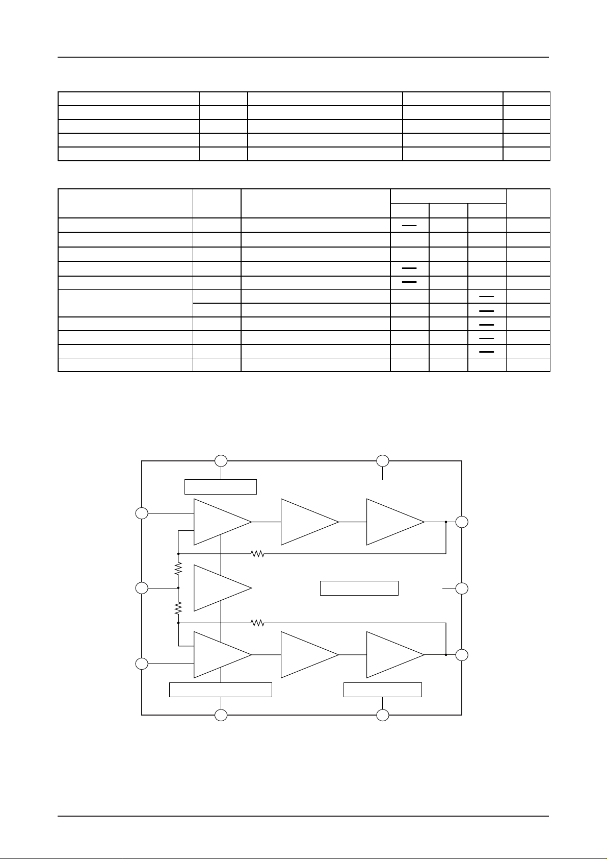
Block Diagram
Standby
7
Standby switching
V
CC
4
µA
CH1 input
Small signal
GND
CH2 input
10
CH1 input
amplifier
R
R
Nf1
9
R
Nf2
REF
amplifier
R
CH2 input
8
amplifier
Pop noise prevention block
Predrive
amplifier
f1
TSD protector
f2
Predrive
amplifier
Output
amplifier
Output
amplifier
Ripple filter
CH1 output
1
Large signal
2
GND
CH2 output
3
6 5
P.P
Filter
No. 6013-2/7
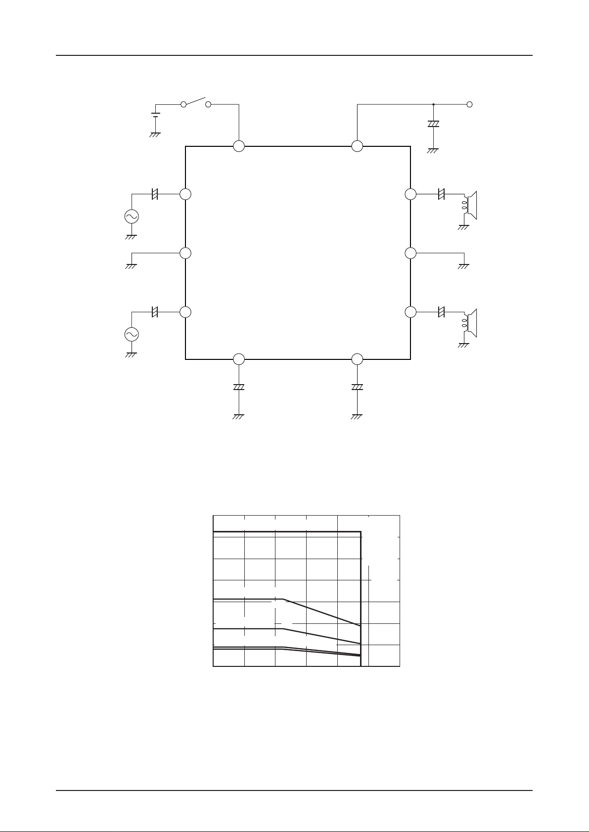
Sample Application
LA4601
+5V
0.22µF
0.22µF
+
1000µF
7
STANDBY
+
ch1
10
Input
PRE GND
9
+
ch2
8
Input
LA4601
4
V
CC
Output
POWER GND
Output
ch1
ch2
+
1
1000µF
4Ω
2
+
3
1000µF
4Ω
P.P Filter
6
+
5
+
4.7µF 100µF
28
With an arbitrary large heatsink
25
24
20
16
100X100X1.5mm
12
50X50X1.5mm
8
With recommended substrate
4
IC only
Allowable power dissipation, Pd max – W
0
–20 0 20 40 60 80 100
Pd max – Ta
3
12.5
3
7.0
3.2
AI heatsink
fastening
torque
39N•cm
3.6
Ambient temperature, Ta – ˚C
Apply
silicone
grease
No. 6013-3/7
 Loading...