

SANYO LA4555 Datasheet
Any and all SANYO products described or contained herein do not have specifications that can handle
applications that require extremely high levels of reliability, such as life-support systems, aircraft’s
control systems, or other applications whose failure can be reasonably expected to result in serious
physical and/or material damage. Consult with your SANYO representative nearest you before using
any SANYO products described or contained herein in such applications.
SANYO assumes no responsibility for equipment failures that result from using products at values that
exceed, even momentarily, rated values (such as maximum ratings, operating condition ranges,or other
parameters) listed in products specifications of any and all SANYO products described or contained
herein.
Monolithic Linear IC
2-Channel AF Power Amplifier
for Radio, Tape Recorder Use
Ordering number:ENN1697B
LA4555
SANYO Electric Co.,Ltd. Semiconductor Company
TOKYO OFFICE Tokyo Bldg., 1-10, 1 Chome, Ueno, Taito-ku, TOKYO, 110-8534 JAPAN
Features
• Low quiescent current.
• On-chip 2 channels permitting use in stereo and bridge
amplifier applications.
• High output.
• Minimum number of external parts required.
(9 pcs. munimum)
• Good ripple rejection (at steady state).
• Soft tone at the output saturation mode.
• Good channel separation.
• Easy thermal design.
• Small pop noise at the time of power supply ON/OFF.
Specifications
Absolute Maximum Ratings at Ta = 25˚C
retemaraPlobmySsnoitidnoCsgnitaRtinU
egatlovylppusmumixaMV
noitapissidrewopelbawollAxamdP
erutarepmetgnitarepOrpoT 57+ot02–
erutarepmetegarotSgtsT 051+ot55–
xam 31V
CC
).nrettap
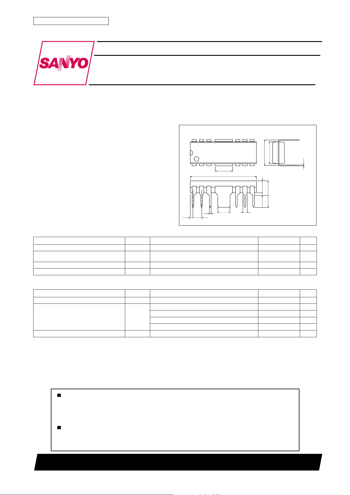
Package Dimensions
unit:mm
3022A-DIP12F
[LA4555]
12
1
0.81
0.5
2.54
5.12
19.4
3.6
1.3
tiucricdetnirpelpmaseeS(BCPdednemmocerhtiW
7
7.62
6.45
0.4
6
3.46
4.26max
3.5
0.51min
SANYO : DIP12F
4W
˚C
˚C
Operating Conditions at Ta = 25˚C
retemaraPlobmySsnoitidnoCsgnitaRtinU
egatlovylppusdednemmoceRV
ecnatsiserdaoLR
egnaregatlovgnitarepOV
CC
L
po 21ot6.3V
CC
V6oeretS 8ot2
V6LTB 8ot4
V9oeretS 8ot4
V9LTB 8
21800TN (KT)/90196RM/O147KI/5275MW, TS No.1697–1/10
9,6V
Ω
Ω
Ω
Ω
LA4555
Operating Characteristics at Ta = 25˚C, VCC=9V, f=1kHz, Rg=600Ω, RL=4Ω, ( ) : RL=8Ω,
See specified Test Circuit.
retemaraPlobmySsnoitidnoC
tnerructnecseiuQoccI
niagegatloVGVV,0=fR
ecnereffidniagegatloV
rewoptuptuOP
noitrotsidcinomrahlatoTDHTPOWm052=3.05.1%
ecnatsisertupnIir1203kΩ
egatlovesiontuptuOV
noitcejerelppiRrRV,zH001=f,0=gR
klatssorCTCk01=gR Ω mBd0=oV,zHk1=f,0485Bd
∆ GV
O
ON
V9oeretS5103Am
V6oeretS31Am
mBd15–=941535Bd
NI
V,0=fR
0=gR5.00.1Vm
k01=gR Ω 8.00.2Vm
mBd15–=1±Bd
NI
oeretS,V6,%01=DHT7.00.1W
LTB,%01=DHT8.2W
oeretS,V9,%01=DHT7.13.2W
LTB,%01=DHT)5.4(W
Vm051=0484Bd
R
nimpytxam
sgnitaR
tinU
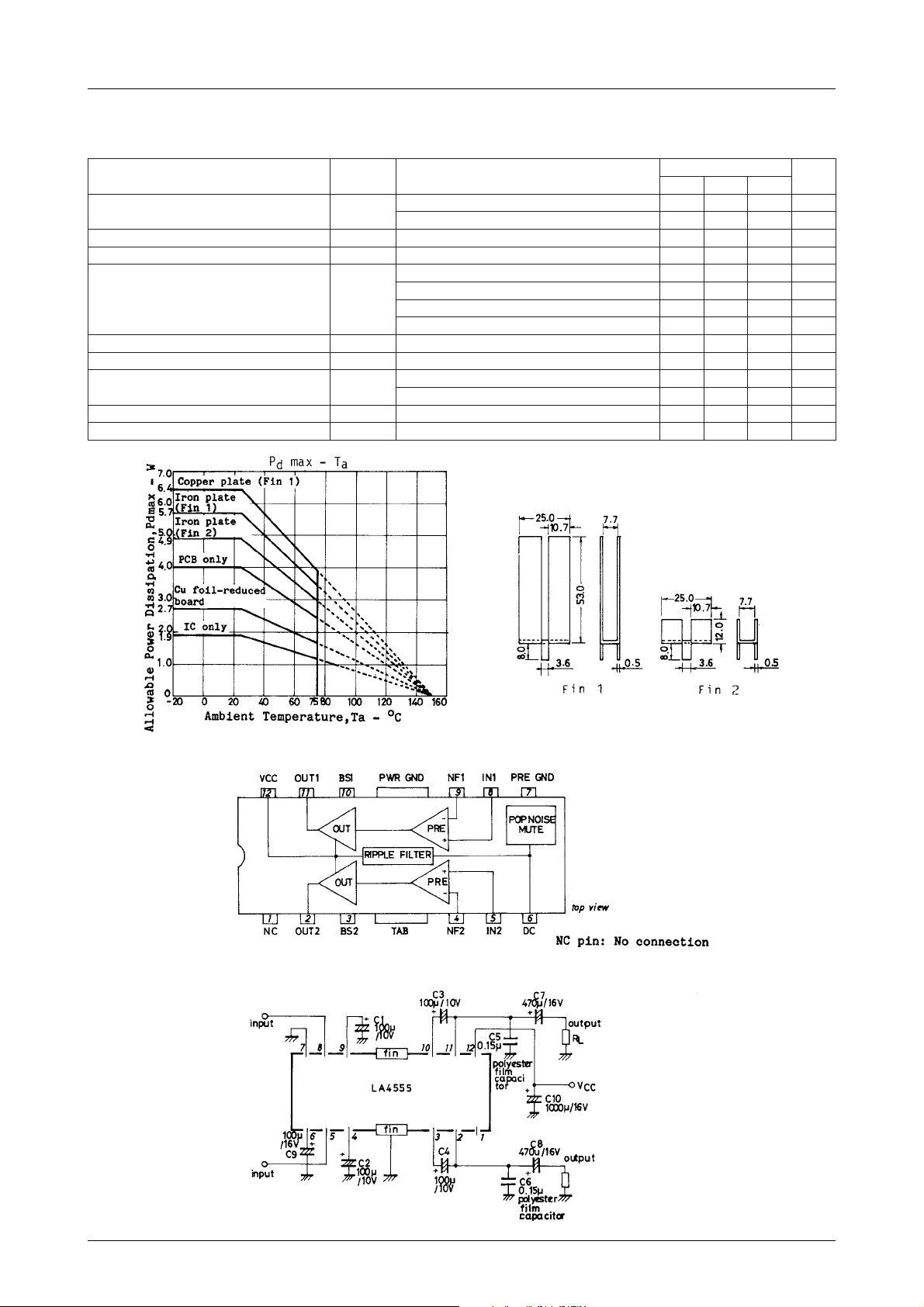
Equivalent Circuit Block Diagram
Sample Application Circuit : Stereo Use
No.1697–2/10
LA4555
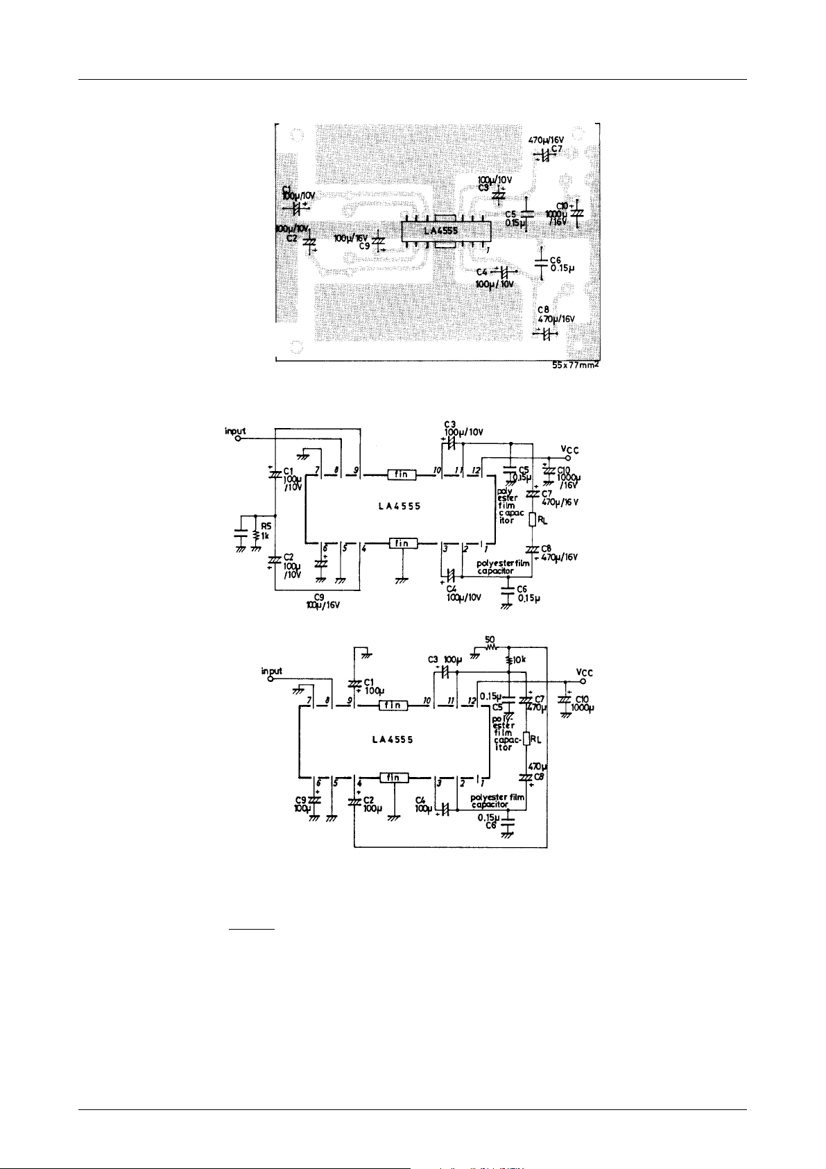
Sample Printed Circuit Pattern (Cu-foiled side)
Sample Application Circuit : Bridge Amplifier Use 1
Sample Application Circuit : Bridge Amplifier Use 2
Description of External Parts
C1 (C2) : Feedback capacitor. The low cutoff frequency is determined by the following formula.
fL=
Since this capacitor as well as decoupling capacitor affects the starting time, the capacitor value must be f ix ed
with the necessary low frequency band fully considered.
C3 (C4) : Bootstrap capacitor. The output at low frequencies depends on this capacitor. Decreasing the capacitor value
lowers the output at low frequencies. A capacitor value of 47µF or more is required.
C5 (C6) : Oscillation blocking capacitor. Use a polyester film capacitor that is good in high frequency response and
temperature characteristic. The use of an electrolytic capacitor, ceramic capacitor may cause oscillation to
occur at low temperatures.
1
2πC1Rf
fL : Low cutoff frequency
Rf : Feedback resistance
Continued on next page.
No.1697–3/10
 Loading...