

Page 1

SU4H/UF2 (FVH-T619 GB) Tue. Mar. 09/1999
Language Contents
OPERATING INSTRUCTIONS
FVH-T619
Video Cassette Recorder
®
Only cassettes marked w can be used with this video cassette recorder.
NERGY STAR
®
Partner,
®
guidelines for
As an E
FISHER has determined that this
product or product model meets
the E
NERGY STAR
energy efficiency.
Please read this manual and accompanying “IMPORTANT SAFETY INSTRUCTIONS” sheet carefully before
connecting your VCR and operating it for the first time.
Be sure to read carefully and follow all the PRECAUTIONS on page 2.
Keep the manual in a safe place for future reference.
NOTE: Locate serial number (shown on rear panel of unit) and recor d it here ➡
(CA)
Page 2

SU4H/UF2 (FVH-T619 GB) Tue. Mar. 09/1999
PRECAUTIONS
CAUTION
RISK OF ELECTRIC SHOCK
DO NOT OPEN
CAUTION: TO REDUCE THE RISK OF ELECTRIC SHOCK,
REFER SERVICING TO QUALIFIED SERVICE PERSONNEL.
DO NOT REMOVE COVER (OR BACK).
NO USER-SERVICEABLE PARTS INSIDE.
The lightning flash with arrowhead symbol, within an
equilateral triangle, is intended to alert the user to the
presence of uninsulated “dangerous voltage” within the
product’s enclosure that may be of sufficient magnitude
to constitute a risk of electric shock to persons.
The exclamation point within an equilateral triangle is
intended to alert the user to the presence of important
operating and maintenance (servicing) instructions in
the literature accompanying the product.
WARNING: To reduce the risk of fire or electric
shock, do not expose this appliance to rain or
moisture.
CAUTION: To prevent electric shock, match wide
blade of plug to wide slot of electrical outlet and
insert fully.
CAUTION: Changes or modifications not expressly
approved by the manufacturer may void the user’s
authority to operate this VCR.
Location
For safe operation and satisfactory performance of your
VCR, keep the following in mind when selecting a place
for its installation:
œ Shield it from direct sunlight and keep it away from
sources of intense heat.
œ Avoid dusty or humid places.
œ Avoid places with insufficient ventilation for proper heat
dissipation. Do not block the ventilation holes of the
VCR. Do not place the unit on a carpet because this
will block the ventilation holes.
œ Install the VCR in a horizontal position only.
œ Avoid locations subject to strong vibrations.
œ Avoid moving the VCR between cold and hot locations
(see “Moisture Condensation Problems”, this page).
œ Do not place the VCR directly on top of the TV, as this
may cause playback or recording problems.
WARNING: Unauthorized recording or use of
television broadcast, video tape, film or other
copyrighted material may violate applicable
copyright laws. The manufacturer assumes no
responsibility for unauthorized duplication, use or
other acts that infringe upon the rights of copyright
owners.
Declaration of Conformity
Model Number : FVH-T619
Trade Name : Fisher
Responsible party : SANYO FISHER COMPANY
Address : 21605 Plummer Street,
Chatsworth, California 91311
Telephone No. : (818) 998-7322
œ This device complies with Part 15 of the FCC Rules.
Operation is subject to the following two conditions:
(1) this device may not cause harmful interference,
and
(2) this device must accept any interference
received, including interference that may cause
undesired operation.
Moisture Condensation Problems
Cause:
When the VCR is first installed, moved from a cold area
to a warm area or placed in a location with high humidity,
dew (moisture) may form inside the unit. If you operate
the VCR with dew inside, damage may result.
Avoiding Electric Shock or Fire
œ Do not handle the power cord with wet hands.
œ Do not pull on the power cord when disconnecting it
from an AC wall outlet. Grasp it by the plug.
œ If any liquid is spilled on the VCR, unplug the power
cord immediately and have the unit inspected at a
factory-authorized service center.
œ Do not place anything directly on top of the VCR.
Prevention:
1 Make all necessary connections.
2 Plug the power cord into a 120 V AC wall outlet.
3 Turn on the power.
4 Do not operate the VCR or insert a cassette for
approximately 2 hours.
This allows the VCR to warm up to the temperature of the
room where it will be used.
Technology licensed by
Laboratories Inc.
This VCR has a Y/C filtering
technique incorporated under license
from Faroudja Laboratories Inc.
2
Page 3

SU4H/UF2 (FVH-T619 GB) Tue. Mar. 09/1999
FEATURES
TIMER/CLOCK
œ Selectable standard/daylight saving time
œ 1-year/8-event program timer with daily/weekly settings
œ Smart Time Record function
œ Smart Speed Record function
œ Remaining tape duration display
œ Quick timer recording (QTR)
œ Off timer (up to 6 hours)
AUDIO/VIDEO
œ VHS Hi-Fi stereo audio recording and playback
œ MTS stereo/second audio program (SAP) recording and
playback
œ Digitally-adjusted clean playback
SPECIAL PLAYBACK/SEARCH
œ Ad JUMP™
œ Recording contents on-screen list (Rec. List Super)
œ Double-Azimuth 4-head video recording/playback system for
clean special playback:
Forward/reverse search, double-speed playback, clean still
image, frame advance, variable-speed slow motion
œ High-speed fast forward/rewind
œ Zero search
œ Index search
AUTOMATIC FUNCTIONS
œ Automatic clock setting and adjustment
œ Endless playback
œ Automatic digital tracking
œ Automatic channel programming
œ Full auto playback functions: power-on, rewind, eject, record
auto cancel, power-off eject
GENERAL
œ Multilanguage, multicolor on-screen menu
œ Multibrand universal remote control with Moonlight™ buttons
œ Vibration-suppressing mid-mount design
œ Child lock
œ Front/rear audio/video inputs
ACCESSORIES
Make sure that all the accessories listed below have been
included with your VCR.
Power cord Multibrand universal
remote control
CONTENTS
Precautions . . . . . . . . . . . . . . . . . . . . . . . . . . . . . . . . . . . 2
Features . . . . . . . . . . . . . . . . . . . . . . . . . . . . . . . . . . . . . 3
Accessories . . . . . . . . . . . . . . . . . . . . . . . . . . . . . . . . . . . 3
DESCRIPTION
VHS video cassette tapes . . . . . . . . . . . . . . . . . . . . 4
Locations of controls and indicators . . . . . . . . . . . . . 5
Multibrand universal remote control . . . . . . . . . . . . . 8
CONNECTIONS
Basic antenna/cable connections . . . . . . . . . . . . . . 11
Alternative cable TV connections . . . . . . . . . . . . . . 12
Audio/video connections . . . . . . . . . . . . . . . . . . . . 14
BASIC OPERATION
Initial setup . . . . . . . . . . . . . . . . . . . . . . . . . . . . . . . 15
Multifunction on-screen displays . . . . . . . . . . . . . . 17
On-screen menu . . . . . . . . . . . . . . . . . . . . . . . . . . . 18
Setting the clock . . . . . . . . . . . . . . . . . . . . . . . . . . . 20
Changing the menu language . . . . . . . . . . . . . . . . 22
Programming channels . . . . . . . . . . . . . . . . . . . . . 22
Viewing TV only . . . . . . . . . . . . . . . . . . . . . . . . . . . 23
Playing a rental tape . . . . . . . . . . . . . . . . . . . . . . . . 23
Normal playback . . . . . . . . . . . . . . . . . . . . . . . . . . . 24
Tracking control . . . . . . . . . . . . . . . . . . . . . . . . . . . 24
Recording . . . . . . . . . . . . . . . . . . . . . . . . . . . . . . . . 25
Rec. List super . . . . . . . . . . . . . . . . . . . . . . . . . . . . 26
ADVANCED USE
VHS Hi-Fi audio and MTS broadcasts . . . . . . . . . . 28
Audio output mode . . . . . . . . . . . . . . . . . . . . . . . . . 29
Special playback . . . . . . . . . . . . . . . . . . . . . . . . . . 30
Zero search . . . . . . . . . . . . . . . . . . . . . . . . . . . . . . 32
Index search . . . . . . . . . . . . . . . . . . . . . . . . . . . . . . 32
Program timer recording . . . . . . . . . . . . . . . . . . . . . 33
Quick timer recording (QTR) . . . . . . . . . . . . . . . . . 37
Child lock . . . . . . . . . . . . . . . . . . . . . . . . . . . . . . . . 38
Ad JUMP™ . . . . . . . . . . . . . . . . . . . . . . . . . . . . . . . 38
Copying a tape . . . . . . . . . . . . . . . . . . . . . . . . . . . . 39
75-ohm coaxial cable
Two AA batteri e s (1 .5 vo lt)
Remote control code label
XXXX: XXXXXXXX
XXXX: XXXXXXXX
XXXX: XXXXXXXX
XXXX: XXXXXXXX
Quick Start Guide
Q
u
ic
x
x
x
x
x
x
x
x
x
x
x
x
x
x
x
x
x
x
x
x
x
x
x
x
x
x
x
x
x
x
x
x
x
x
x
x
x
x
x
x
x
x
x
x
x
x
x
x
x
x
x
x
x
x
x
x
x
x
x
x
x
x
x
x
x
x
x
x
x
x
x
x
x
x
x
x
x
x
x
x
x
x
x
x
x
x
x
x
x
x
x
x
x
x
x
x
x
x
x
x
x
x
x
x
x
x
x
x
x
x
x
x
x
x
x
x
x
x
x
x
x
x
x
x
x
x
x
x
x
x
x
x
x
x
x
x
x
x
x
x
x
x
x
x
x
x
x
x
x
x
x
x
x
x
x
x
x
x
x
x
x
x
x
x
x
x
x
x
x
x
x
x
x
x
x
x
x
x
x
x
x
x
x
x
x
x
x
x
x
x
x
x
x
x
x
G
u
k
S
x
x
x
x
x
x
x
x
x
x
x
x
x
x
x
x
x
x
x
x
x
x
x
x
ía
rá
x
x
t
x
a
rt G
x
x
x
x
x
x
x
x
x
x
x
x
x
x
x
x
x
x
x
x
x
x
x
x
x
x
x
x
x
p
x
x
id
x
x
x
x
x
x
a
x
x
x
x
x
x
u
x
x
x
x
x
x
id
x
x
x
x
x
x
x
x
e
x
x
x
x
x
x
x
x
x
x
x
x
x
x
x
x
x
x
x
x
x
x
x
x
x
x
x
x
x
x
x
x
x
x
x
x
x
x
x
x
x
x
x
x
x
x
x
x
x
x
x
x
x
x
x
x
x
x
x
x
x
x
x
x
x
x
x
x
x
x
x
x
x
x
x
x
x
x
x
x
x
x
x
x
x
x
x
x
x
x
x
x
x
x
x
x
x
x
x
x
x
x
x
x
x
x
x
x
x
x
x
x
x
x
x
x
x
x
x
x
x
x
x
x
x
x
x
x
x
x
x
x
x
x
x
x
x
x
x
x
x
x
x
x
x
x
x
x
x
x
x
x
x
x
x
x
x
x
x
x
x
x
x
x
x
x
x
x
x
x
x
x
x
x
x
x
x
x
x
x
x
x
x
x
x
x
x
x
x
x
x
x
x
x
x
x
x
x
x
x
x
x
x
x
x
x
x
x
x
x
x
x
x
x
x
x
x
x
x
x
x
x
x
x
x
Maintenance . . . . . . . . . . . . . . . . . . . . . . . . . . . . . . . . . 39
Troubleshooting guide . . . . . . . . . . . . . . . . . . . . . . . . . 40
Specifications . . . . . . . . . . . . . . . . . . . . . . . . . . . . . . . . 41
3
Page 4
SU4H/UF2 (FVH-T619 GB) Tue. Mar. 09/1999
VHS VIDEO CASSETTE TAPES
Record/Play Times
Tape Length T-60 T-120 T-160
SP Mode 1 hour
LP Mode
(playback only)
Tape Speed
EP Mode 3 hours
(60 minutes)
2 hours
(120 minutes)
(180 minutes)
2 hours
(120 minutes)
4 hours
(240 minutes)
6 hours
(360 minutes)
NOTE: This unit cannot record in LP mode.
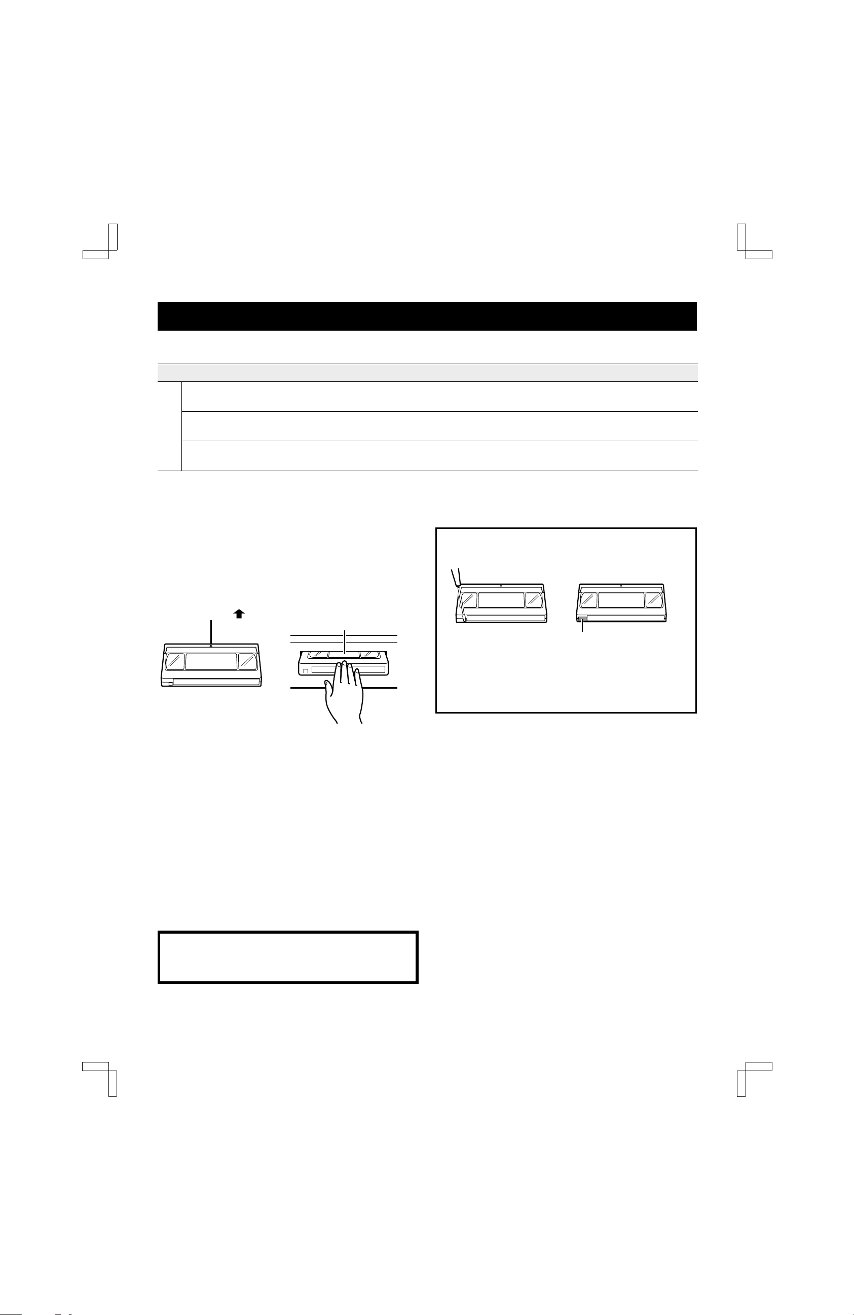
When Handling Video Cassettes
œ Do not expose video cassettes to extreme heat, high
humidity or strong magnetic fields.
œ Do not tamper with the cassette mechanism.
œ Do not touch the tape with your fingers.
œ Always store an unused cassette in its case.
Arrow mark ( ) Label side up
(Arrow pointing toward slot)
2-2⁄3 hours
(160 minutes)
5-1⁄3 hours
(320 minutes)
8 hours
(480 minutes)
Safety Tab
To prevent accidental
erasure, remove the
tab after recording.
highest video quality
excellent video quality
good video quality (longest
recording time)
To record again, cover
the hole with vinyl tape.
Loading
1 Gently push the center of the cassette until it is drawn
in automatically.
The clock display changes to the tape counter
display automatically and the Tape-In icon
lights.
NOTES:
œ If the cassette is not inserted correctly, it will be ejected
in approximately 3 seconds.
œ Do not try to pull the cassette out once automatic
loading starts.
œ Do not force the cassette into the VCR.
CAUTION: To avoid possible injury or accident, keep
children away from this unit. Do not put your hand or
other objects into the cassette loading slot.
(o)
Unloading
1 When in the STOP mode, press the STOP/EJECT
button on the front panel. In any other mode, press
the button twice.
The tape counter display changes to the clock
display automatically.
2 After the cassette appears in the loading slot, gently
pull it out.
AUTO POWER-OFF/EJECT: The cassette is ejected
when the STOP/EJECT button on the front panel is
pressed, even if the VCR’s power is off. (The power cord
must be connected to an AC wall outlet.)
4
Page 5

SU4H/UF2 (FVH-T619 GB) Tue. Mar. 09/1999
LOCATIONS OF CONTROLS AND INDICATORS
Front Panel
21 3 54
hPAUSE/STILL
POWER
f
c
REW
PLAY
e
FF
AV INPUT
CHANNEL
L-AUDIO-RVIDEO
H
Reference pages are shown in square brackets.
G
1 POWER button
2 Cassette loading slot
3 REW (rewind) button [30]
This button is used both for rewind and reverse
picture search.
4 PAUSE/STILL button [25, 30]
œ Press this button in the record mode to
temporarily stop a recording (PAUSE).
œ Press this button in the playback mode to view a
still frame (STILL).
œ Press this button repeatedly in the still mode to
advance the picture one frame at a time.
5 FF (fast forward) button [30]
This button is used both for fast forward and
forward picture search.
6 PLAY button [24]
7 STOP/EJECT button [4, 24]
aREC
bSTOP/iEJECT
9 8 7 6F
8 REC (record) button [25, 37]
9 Indicator panel [6]
F Remote control sensor
G CHANNEL selection buttons (l and j) [16, 24, 37]
H Front-panel AUDIO/VIDEO input jacks [25, 39]
Connect the audio and video outputs from an
external unit (i.e. a video camera, second VCR) to
these jacks. To record the signals coming from the
external unit, press the INPUT button on the
remote control to display “L2” instead of a channel
number (see page 25). If only one audio jack is to
be used, connect it to the L (left) jack.
Auto A/V Selection
There is no need to unplug the VCR from the TV to
view another video source on-screen. When the
VCR power is off and the output cable from an
external unit is connected to these front A/V input
jacks, the signal from the external unit is
automatically sent to the connected TV screen.
NOTE: The POWER, STOP/EJECT, REC,
PAUSE/STILL, FF, PLAY and REW buttons illuminate
according to each VCR mode.
5
Page 6

SU4H/UF2 (FVH-T619 GB) Tue. Mar. 09/1999
LOCATIONS OF CONTROLS AND INDICATORS
Indicator Panel
1234
C
SAP
ST
8F9G
REC
OFF
AM LR
VCR
PM
SP LP EP
567
Operation Icons
Play,
Forward
Search, Slow
Reverse
Search
Fast
forward
Rewind
JKLM
(blinking) (blinking)
Record Record pause
1 Operation Icons (see below).
2 VCR indicator
Use the TV/VCR button on the remote control to turn
this indicator ON or OFF.
ON: for playback, VCR programming or watching
TV programs through the VCR tuner
OFF: for watching TV programs through TV tuner
3 Audio output indicators (Left and Right)
4 Tape-In icon
5 Tape Speed indicators
6 Clock/ Tape Counter/ QTR (Quick Timer Recording)
indicators
7 Timer icon
8 ST (stereo) indicator
9 Input source indicator:
Channel number or audio/video input (L1 or L2)
F SAP (Second Audio Program) indicator
G CATV indicator
PP and O
(blinking)
Still Frame advance
J and OJ and N
(blinking)
Example of Indications
POWER OFF POWER ON
CATV
indicator
Channel indicator
Clock Audio output
indicators
AM
Tape speed indicator
CATV
indicator
C AM LR
Channel indicator
Clock Audio output
indicators
SP
Tape speed indicator
6
Page 7

SU4H/UF2 (FVH-T619 GB) Tue. Mar. 09/1999
LOCATIONS OF CONTROLS AND INDICATORS
Back Panel
13
AC IN
AC power input
1
2 Rear-panel AUDIO/VIDEO input jacks
Connect the audio and video outputs from an
external unit (i.e. a video camera, second VCR) to
these jacks. To record the signals coming from the
external unit, press the INPUT button on the
remote control to display “L1” instead of a channel
number (see page 25). If only one audio jack is to
be used, connect it to the L (left) jack.
2
VHF/UHF
FROM ANT.
56
IN
TO TV
OUT
4
RF
CHANNEL
34
7
IN OUT
VIDEO
L
AUDIO
R
4 VHF/UHF antenna output jack
5 VIDEO output jack (yellow)
6 AUDIO output jacks (Red for right and white for left)
7 RF CHANNEL switch
3 VHF/UHF antenna input jack
7
Page 8

SU4H/UF2 (FVH-T619 GB) Tue. Mar. 09/1999
MULTIBRAND UNIVERSAL REMOTE CONTROL
This universal remote control will operate the basic functions of TVs and cable (CATV) converters/decoders matching
the brands shown on pages 9 and 10.
Locations of Controls
1
2
123
3
4
456
789
100/ENTER
POWER
0
CH/TRACK
5
6
7
8
9
PAUSE/STILL
REW FFPLAY
STOP
CLEARTV/VCRMENU
N
SET
O
REC
P
Q
R
Reference pages are shown in square brackets.
1 TV/VCR mode button [15]
Lets you select TV or VCR mode. When VCR mode
is selected, the VCR indicator lights on the front panel.
2 MENU button [18]
3 Number buttons (0 – 9) [16, 21]
4 100/ENTER button [16]
5 POWER button
6 CH (channel) selection/TRACK (tracking) buttons
(l and j) [15, 16, 24, 37]
7 PAUSE/STILL button [25, 30]
8 REW (rewind) button [30]
9 STOP button [24]
F VCR, CATV/DSS and TV remote control mode
buttons [9, 10, 15]
Lets you select the unit to be operated (VCR, TV or
cable converter/DSS receiver).
G TYPE button [27]
H SLOW button [30]
CATV/DSS
TVVCR
F
TYPE
SLOW VOL+
x2
G
H
I
J
K
L
M
NOTE: The shaded buttons are used for VCR operation
only.
SP/EP
DISPLAY
INPUT RESET
Ad JUMP
INDEX VOL–
Ö0Ü
S
T
U
V
I SP/EP button [25]
J DISPLAY button [17, 32]
K INPUT button [25]
L Tape counter RESET button [32]
M Ad JUMP button [38]
N CLEAR button [16, 21]
O SET button [15, 16, 19]
P REC (record) button [25, 37]
Q PLAY button [24]
R FF (fast forward) button [30]
S x2 button [30]
T VOL (volume) buttons [9]
Increases (+) or decreases (–) TV volume.
U INDEX button [32]
V →0← (Zero Search) button [32]
8
Page 9
SU4H/UF2 (FVH-T619 GB) Tue. Mar. 09/1999
MULTIBRAND UNIVERSAL REMOTE CONTROL
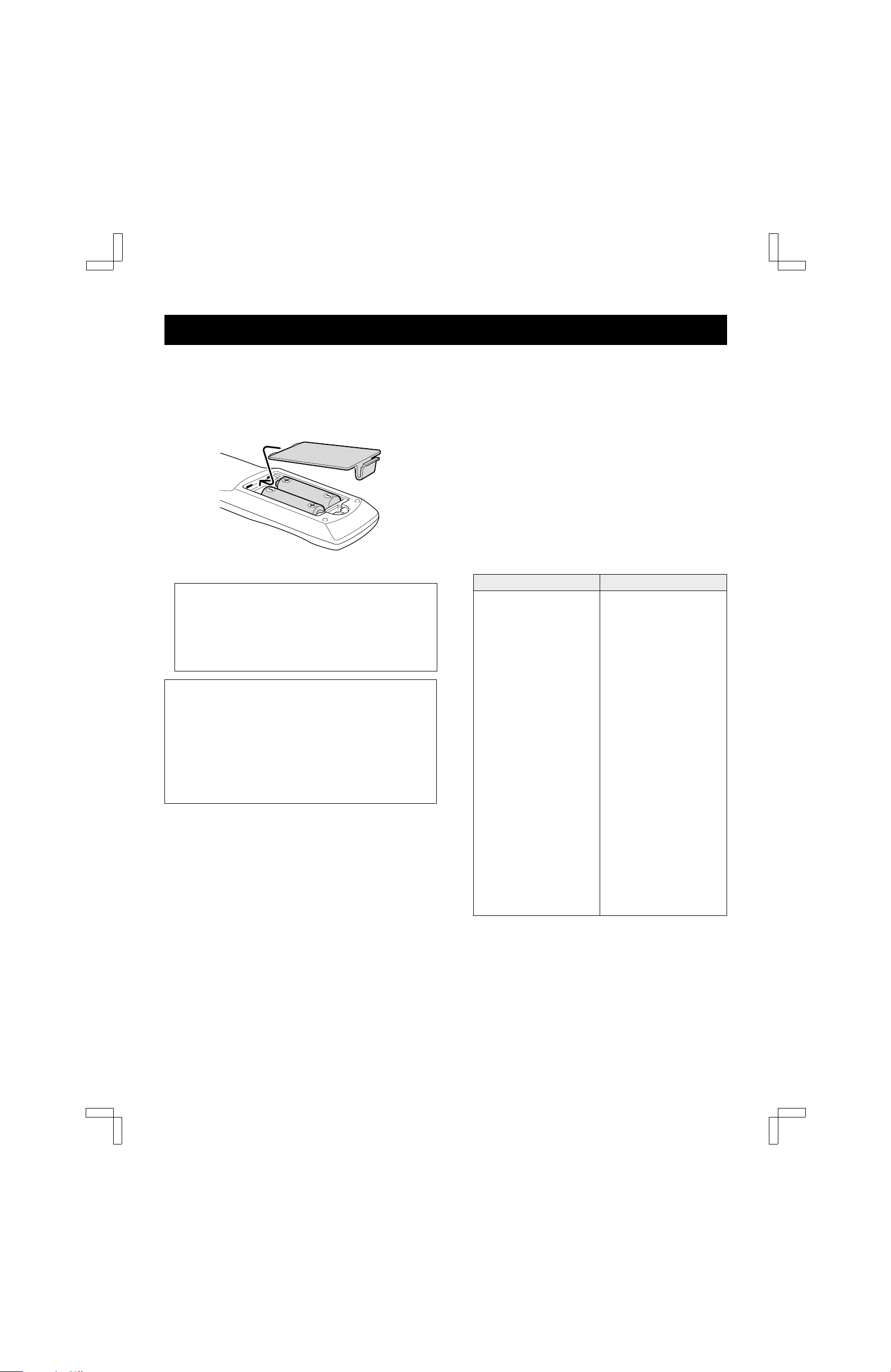
Battery Installation and Operation
1 Install the two supplied AA batteries as shown.
2 Aim the remote control at the VCR and press the
desired buttons to operate.
IMPORTANT NOTE:
SPENT OR DISCHARGED BATTERIES MUST BE
RECYCLED OR DISPOSED OF IN A SAFE
MANNER IN COMPLIANCE WITH ALL
APPLICABLE LAWS.
FOR DETAILED INFORMATION, CONTACT YOUR
LOCAL COUNTY SOLID WASTE AUTHORITY.
Using the remote control
1 Before using the remote control, press the VCR,
TV or CATV/DSS button to select the device to be
operated.
2 To switch the remote control mode (to operate a
different device), be sure to press the VCR, TV or
CATV/DSS button first.
NOTES:
œ The remote control will not operate properly if
something comes between the VCR and the remote
control.
œ The POWER, 0 – 9, 100/ENTER, INPUT and
CH/TRACK l and j buttons are used to operate the
VCR, TV, cable box and DSS receiver.
œ VOL buttons operate TV volume regardless of the
remote control mode selected.
Setting the remote control code
The multibrand universal remote control can operate the
basic functions of TVs and cable (CATV)
converters/decoders made by the manufacturers listed
below.
To enter the remote control code for your brand of TV or
cable converter/decoder, follow the steps below.
For TV operation
1 In the chart below, find the code corresponding to
your brand of TV.
2 While holding down the TV button, enter the 2-digit
code using the number buttons (0 – 9).
The remote control is now set to operate your TV.
TV brands Code
ADMIRAL 05, 10, 13
EMERSON 17
FISHER 03
GE 07
GOLDSTAR 01
HITACHI 02
JVC 15
MAGNAVOX 08
MATSUSHITA 12, 18
MITSUBISHI 14
PANASONIC 12, 18
QUASAR 12, 18
RCA 06
SAMSUNG 16
SANYO 03
SHARP 00, 13
SONY 11
TECHNOL ACE 05
TOSHIBA 04
ZENITH 09, 10
NOTE: There may be some older TV models that
cannot be operated with this remote control. If this is
the case, use the original remote control supplied with
the TV.
9
Page 10

SU4H/UF2 (FVH-T619 GB) Tue. Mar. 09/1999
MULTIBRAND UNIVERSAL REMOTE CONTROL
For cable (CATV) converter/decoder or DSS
(Digital Satellite System) receiver operation
1 In the chart, find the code corresponding to your
brand of cable converter/decoder or DSS receiver.
2 While holding down the CATV/DSS button, press
2 number buttons (0 – 9) to enter the code.
The remote control is now set to operate your
converter/decoder or DSS receiver.
Cable converter/decoder
brands
ARCHER 00, 01, 06, 11, 23, 29
CABLEVIEW 00, 05, 11, 24, 29
CABLETENNA 00, 01
CENTURY 00
CITIZEN 00, 05, 11, 24, 29
CURTIS 19, 25, 32
DIAMOND 00, 01, 29
EAGLE 14, 15, 20
GC BRAND 00, 05, 11, 24, 29
GEMINI 05
GENERAL ELECTRIC 01, 18
GENERAL INSTRUMENT 01, 05, 07, 09, 16, 28, 33
HAMLIN 12, 17
HITACHI 13
JASCO 05
JERROLD 01, 05, 07, 09, 16, 28, 33
MACOM 13
MAGNAVOX 14
MATSUSHITA 08, 21, 41
MOVIETIME 00, 11, 20
NEC 20
NOVAVISION 19, 32
NSC 20
OAK/OAK SIGMA 04
PANASONIC 06, 08, 21, 41
PHILIPS 02, 03, 14, 31
PIONEER 06, 23
PULSER 00, 05, 11, 24, 29
QUEST 06, 23
RADIO SHACK 00
RCA 06, 08, 21, 41
REALISTIC 00
RECOTON 00
REGAL 12, 14, 17
REMBRANDT 00, 01, 11
SAMSUNG 05, 06, 11, 20, 22, 23
SCIENTIFIC ATLANTA 19, 25, 32
SL MARX 00, 05, 06, 11, 20, 22, 24, 27
SPRUCER 06, 08, 21, 41
STANDARD COMPONENTS 00, 11
Code
Cable converter/decoder
brands
STARGATE 00, 05, 06, 11, 20, 22, 24, 29
TEKNIKA 30
TELECAPTION 26
TELEVIEW 05, 06, 11, 20, 22
TOCOM 01, 11, 07, 10
UNIKA 00, 01, 11, 29
UNIVERSAL 00, 11, 24, 27
VIDEOWAY 02, 03, 14
VIEWSTAR 14, 15, 20
ZENITH 02, 03, 14
DSS receiver brands Code
PANASONIC 43
RCA 41
SANYO 40
SONY 42
Code
NOTES:
œ Only remote-controlled products can be operated using
this remote control. (Refer to the instruction manuals
for your TV, CATV converter/decoder or DSS receiver
instruction manual for more details.)
œ There may be some TV, CATV converter/decoder or
DSS receiver models that cannot be operated with this
remote control. If this is the case, use the original
remote control supplied with your equipment.
œ Cable companies may charge an extra monthly fee to
activate the remote control feature of a rented CATV
converter/decoder. If this is the case, this remote
control will not operate the cable converter/decoder
unless such arrangements are made with the cable
company.
IMPORTANT NOTE: If the batteries in the remote
control are replaced, the codes for the TV , CATV
converter/decoder and DSS receiver must be reset.
Write your code numbers below for future reference.
TV: ______ CATV: ______ DSS: ______
Place the supplied label on the back of the remote control.
10
Page 11

SU4H/UF2 (FVH-T619 GB) Tue. Mar. 09/1999
BASIC ANTENNA/CABLE CONNECTIONS
Antenna
75 ohm
antenna
cable
or
AC Wall
1
outlet
CABLE TV
4
5
1 Connect an antenna (or a cable TV system) to the
VCR.
2 Set the RF CHANNEL switch on the back of the VCR
to 3 or 4.
3 Connect the VCR to the TV with the 75 ohm coaxial
cable (supplied).
4 Plug the power cord (supplied) into the AC power
input (AC IN ~) on the VCR back panel. Insert the
plug firmly.
VCR
(Back panel)
RF
CHANNEL
AC IN
2
VHF/UHF
FROM ANT.
TO TV
43
IN
OUT
(supplied)
TV
(Back panel)
VHF/UHF
ANTENNA
IN
3
Channel Switch Setting
Set your TV to either channel 3 or channel 4. Then set
the VCR’s RF CHANNEL switch to channel 3 or 4 to
match the channel selected on the TV. This is your VCR
channel. The TV must be set to this channel whenever
the VCR is used for playing a tape or watching a TV
program. If in doubt, check with your local cable company.
5 Insert the plug end of this power cord into a wall
outlet.
NOTES:
œ If you have a cable converter connected to your TV,
see “ALTERNATIVE CABLE TV CONNECTIONS”,
next page.
œ If your antenna has a twin-lead cable or your TV has
screw-type antenna terminals, use a matching
transformer (not supplied).
300 ohm
Twin-lead Cable
Matching Transformer
(not supplied)
11
Page 12

SU4H/UF2 (FVH-T619 GB) Tue. Mar. 09/1999
ALTERNATIVE CABLE TV CONNECTIONS
Your VCR can receive all unscrambled cable channels
without the use of an external converter. If you wish to
view and record scrambled cable channels, you must
connect a converter/decoder as described below.
Your local cable TV company will advise you of the
channels available in your area.
We recommend that you consult your cable TV company
to make sure that the cable is properly connected.
When the TV does not have a built-in cable converter
Connect the cable TV converter between the VCR and
the TV so that you can watch a cable TV program while
recording another program.
VCR
CATV
(Back panel)
75 ohm
coaxial
cable
AC IN
RF
CHANNEL
VHF/UHF
FROM ANT.
TO TV
43
IN
OUT
(supplied)
NOTE: Set the TV channel to the cable converter output
channel (CH02 ~ 07).
Cable
converter
IN OUT
TV
(Back panel)
VHF/UHF
ANTENNA
IN
(not supplied)
When you have both cable and pay TV (scrambled channels)
NOTES:
œ With this method the TV and VCR receive the same
channel. Recording one program while watching
another is not possible.
Cable
converter/
VCR
(Back panel)
Decoder
CATV
75 ohm
coaxial cable
NOTE TO CATV SYSTEM INSTALLER (USA only): This
reminder is provided to call the CATV system installer’s
attention to Article 820-40 of the NEC that provides
guidelines for proper grounding and, in particular,
AC IN
CHANNEL
œ With this connection, the VCR must be set to the cable
converter/decoder output channel. (See next page.)
VHF/UHF
FROM ANT.
IN
RF
TO TV
43
OUT
(supplied)
specifies that the cable ground shall be connected to the
grounding system of the building, as close to the point of
cable entry as practicable.
TV
(Back panel)
VHF/UHF
ANTENNA
IN
12
Page 13

SU4H/UF2 (FVH-T619 GB) Tue. Mar. 09/1999
ALTERNATIVE CABLE TV CONNECTIONS
Cable converter/decoder output channel setup
1 Be sure the cable connections are correct.
(See page 12.)
2 Turn on the TV, VCR and cable converter/decoder.
3 Set the TV to channel 3 or 4.
4 Press the VCR button on the remote control to select
the VCR operation mode.
5 If the VCR indicator is off, press the TV/VCR button
on the remote control.
The VCR indicator lights.
NOTE: If the initial setup has not yet been
completed, the “Auto Setup” message will appear. In
that case, first follow steps 5 – 7 under “INITIAL
SETUP” on page 15.
6 Press the MENU button on the remote control.
The main MENU appears.
@@@@@@@@@MENU
Timer@program
VCR@setup
Clock@set
Language@select
Rec.List@super
Auto@tuning@memory
[CH§‡]†Select
[SET]†OK@@@@@@[MENU]†TV
7 Press the CH/TRACK l (or j) button to select the
VCR setup option, then press the SET button.
The VCR setup menu appears.
CATV/TV@@@@@@@…CATV@TV
Cable@box@@@@@…No@@@Ch02
MTS@@@@@@@@@…ST@SAP@Mono
Audio@out@@@…ST@L@R@Mono
Child@Lock@@@@@On@@…Off
Off@timer@@@…Off@2Hr@6Hr
Auto@AV@Select@On@@…Off
8 Press the CH/TRACK l (or j) button to select the
Cable box option.
9 Press the SET button to set your cable
converter/decoder output channel. The output
channel should be indicated on the cable
converter/decoder back panel. If not, please refer to
the cable converter/decoder instruction manual for
details.
Press the
press the button, the selection changes:
No → Ch02 → Ch03 ... Ch07.
The selection is indicated by the “ z” next to it.
SET
button repeatedly. Each time you
NOTE: Select “No” if you are not using the cable box.
F When finished, press the MENU button to exit the
menu display.
IMPORTANT NOTES:
When the cable converter/decoder output channel is
selected as described above,
œ The VCR tuner remains set to receive the same
channel as the output channel of the cable
converter/decoder. Auto channel programming and
manual channel selection using the VCR tuner are
not possible.
œ If you turn on the cable converter/decoder after
turning on the VCR, no image will appear on the TV
screen. In this case, turn off the VCR, then turn it on
again.
œ Leave the cable converter/decoder on until timer
recording is complete.
œ For timer recordings, you must select the channel to
be recorded using the channel selector on the cable
converter/decoder.
[CH§‡]†Option
[SET]†Select@@[MENU]†TV
13
Page 14

SU4H/UF2 (FVH-T619 GB) Tue. Mar. 09/1999
AUDIO/VIDEO CONNECTIONS
Stereo Connections
Connecting your VCR to your stereo TV through
audio/video jacks usually provides better picture and
sound quality. It also enables you to play back stereo
broadcast programs in stereo.
When you have a stereo monitor TV
VCR
(Back panel)
AUDIO OUTPUT
L: White
R: Red
VIDEO
AUDIO
VHF/UHF
OUT
FROM ANT.
L
TO TV
R
VIDEO OUTPUT
Yellow
IN
75 ohm coaxial cable (supplied)
OUT
3-wire monitor cable (not supplied)
When you have a monitor TV and a stereo system
Be sure to turn the TV volume all the way down and set
the TV speaker selector switch to EXTERNAL or OFF (to
disconnect the TV speakers). Adjust the volume with the
volume control on the stereo system.
VCR
(Back panel)
VIDEO
L
AUDIO
R
VHF/UHF
OUT
FROM ANT.
IN
TO TV
OUT
75 ohm coaxial cable
(supplied)
Stereo monitor TV
(Back panel)
VIDEO AUDIO IN
VIDEO INPUT
Yellow
VHF/UHF
ANTENNA
IN
LR
IN
AUDIO INPUT
R: Red
L: White
Monitor TV
(Back panel)
VHF/UHF
ANTENNA
VIDEOINAUDIO
Audio receiver
(Back panel)
IN
IN
AUDIO OUTPUT
R: Red
L: White
VIDEO
OUTPUT
Yellow
Video connection cable (not supplied)
Audio connection cable (not supplied)
NOTES:
œ Even when audio/video connections are made, always
make the antenna connection between the VHF/UHF
OUT (VCR) and the VHF/UHF IN (TV) using the
supplied 75-ohm coaxial cable.
VIDEO
INPUT
Yellow
AUDIO INPUT
LR
AUDIO INPUT
L: White R: Red
œ If video and/or audio connections are made between
the VCR and the TV, set the source selector on the
television to A/V input.
14
Page 15

SU4H/UF2 (FVH-T619 GB) Tue. Mar. 09/1999
INITIAL SETUP
When you are setting up the VCR for the first time, or
after the power has failed for more than 5 seconds, follow
the steps below. This AUTO SETUP operation
automatically enters all available channels in your area
into the VCR tuner memory and sets its internal clock.
Many TV stations transmit a signal called Extended Data
Services (XDS). This VCR uses the XDS signal to
automatically set the clock. If no XDS signal is available
in your area, the VCR prompts you to set the clock
manually.
AUTO SETUP
Before starting
œ Be sure the antenna or cable connections are correct.
(See pages 11 and 12.)
1 Turn on the power (TV and VCR).
2 Set the TV to channel 3 or 4.
3 Press the VCR button on the remote control to select
the VCR operation mode.
4 If the VCR indicator is off, press the TV/VCR button
on the remote control.
The VCR indicator lights.
The “Auto Setup” message appears.
@@@@@@@Auto@Setup
5 Press the SET button.
The Language select menu appears.
7 When Auto Tuning is completed, the VCR will select
the channel that carries the XDS signal and proceed
to Auto Clock setting.
@@@@@@@Clock@set
The Auto Clock setting normally takes about
3 minutes. During this time, the VCR’s front panel
shows the channel number that is sending the XDS
signal for Auto Clock setting. Make a note of this
number, which you may need to refer to for
readjusting the clock later (see page 20).
If the Auto Clock setting entered the incorrect date
and/or time, correct it by following the steps under
Automatic Clock Adjustment on page 20.
If no XDS signal is available in your area:
“Clock set” will not appear on the screen when the
Auto Tuning operation is completed. Instead, the TV
program on the lowest channel that the VCR
memorized will appear on screen. In this case, you
must set the clock manually. Follow the steps under
Manual Clock Setting on page 21.
NOTES:
œ During AUTO SETUP, do not press any buttons other
than the ones indicated here.
œ The VCR will search for and memorize channels in the
CATV (cable TV) mode and TV mode. If you are not
using a cable converter/decoder, follow steps 1 – 4
under “PROGRAMMING CHANNELS” on page 22.
œ If the AC power to the VCR is interrupted for more than
5 seconds, the memorized channels may be erased.
BASIC OPERATION
@@@@Language@select
@@@@@@@@English
@@@@@@@@Español
@@@@@@@@Français
6 Press the CH/TRACK l (or j) button to move down
or up the list and highlight the language of your
choice. Press the SET button.
The menu language is selected.
“Auto tuning memory” appears on screen. The VCR
scans all 125 channels and memorizes each active
channel in your area in succession. It takes about
4-6 minutes.
15
Page 16

SU4H/UF2 (FVH-T619 GB) Tue. Mar. 09/1999
INITIAL SETUP
Channel Selection Convenience
You can select a channel on your VCR by using one of
the two methods shown below:
10-KEY RANDOM ACCESS TUNING
Select the desired channel number by using the number
buttons and 100/ENTER button on the remote control.
For single-digit numbers, press 0 first. For channel
numbers higher than 99, press the 100/ENTER button
first.
UP/DOWN SELECTION
Press and hold the CH/TRACK down (l) or up (j) (or
CHANNEL on the front panel) button until the desired
channel is received.
NOTE: When an inactive TV channel is selected on the
VCR, the “No Signal” message appears and the sound is
muted.
Manual Erase
You can eliminate unwanted channels or channels with
weak or scrambled signals from the memorized channel
sequence.
1 Select the channel you want to erase.
2 Press the CLEAR button for about 2 seconds.
“Erase” is displayed on-screen for about 3 seconds.
The channel is now erased from the memory.
Manual Programming
You can add channels to the memorized channel
sequence by manually adding them to the tuner memory.
1 Select the channel you want to add using the number
buttons on the remote control.
2 Press the SET button for about 2 seconds.
“Add” is displayed on-screen for about 3 seconds.
The channel is now added to the memory.
BASIC OPERATION
16
Page 17

SU4H/UF2 (FVH-T619 GB) Tue. Mar. 09/1999
MULTIFUNCTION ON-SCREEN DISPLAYS
Various displays appear, superimposed over the screen
image, indicating the operation mode and features in use.
Operation mode
QTR end time
p QTR10:30PM SAP ST C 10
SPORTS DIGEST
SP 0:00:00 LR 09:30PM
Recording
tape speed
Counter
MTS mode
Channel/AV
Audio output
Program title
Clock
Operation Mode Display
When an operation button is pressed, the corresponding
operation mode icon is displayed in the top left corner of
the screen for about 3 seconds.
NOTE: The recording pause mode icon will remain
displayed until recording is resumed or stopped.
Operation Icon Operation Icon
Play c Record a
Fast-forward c c Record pause a h
Rewind d d
Status display
1 Press the DISPLAY button on the remote control.
The status display appears.
SAP ST C 10
SP 0:00:00 LR 09:30PM
2 To remove the status display, press the DISPLAY
button (press the button twice if a tape is loaded in
the VCR).
NOTE: The status display will not appear if a menu is
displayed on screen, or during special playback.
Remaining Tape Duration Display
1 Press the DISPLAY button twice.
The remaining tape duration appears at the bottom
of the screen. It is calculated in hours and minutes
from the current position to the end of the tape.
BASIC OPERATION
Channel Number and MTS Mode
Displays
The channel number and the MTS mode displays appear
for about 3 seconds when a channel is selected.
Program Title Display
When a channel is tuned or when normal playback is
started, the program title (maximum 24 characters) will be
displayed for about 4 seconds.
NOTES:
œ The program title is only displayed if the broadcast
carries the title information or if it has been recorded on
the tape.
œ Depending on the TV signal or tape condition the
program title may not be displayed even if it is available.
SP Tape remain 2:30
If “
--:--
” is displayed, the remaining tape
duration has not been calculated.
2 To remove the remaining tape duration display, press
the DISPLAY button again.
NOTES:
œ The remaining tape duration display will not appear if a
menu is displayed on screen or during special playback.
œ This feature will not work properly on T-140 tapes or
tapes longer than T-160. (The feature will work on
T-160 tapes.)
œ Depending on the condition and type of tape used, the
VCR may not accurately detect the remaining tape
duration.
17
Page 18

SU4H/UF2 (FVH-T619 GB) Tue. Mar. 09/1999
ON-SCREEN MENU
Your new VCR is designed with user-friendly on-screen
menus to help you operate its many features.
Color-coded menus prompt you step-by-step through
operations by highlighting the sections awaiting your
entries.
Displaying the On-Screen Menus
1 Turn on the power (TV and VCR).
2 Set the TV to channel 3 or 4.
3 Press the VCR button on the remote control to select
the VCR operation mode.
4 If the VCR indicator is off, press the TV/VCR button
on the remote control.
The VCR indicator lights.
NOTE: If the initial setup has not yet been
completed, the “Auto Setup” message will appear.
Follow steps 5 – 7 under “INITIAL SETUP” on page
15.
5 Press the MENU button on the remote control.
The main MENU appears.
Main Menu Options
Reference pages are shown in square brackets.
Timer program [33 – 36]
œ Select this to program, check or cancel a timer
recording setting.
VCR setup [19]
œ Select this to set the VCR functions.
Clock set [20, 21]
œ Select this to set the clock or change the clock
setting.
Language select [22]
œ Select this to change the on-screen language.
Rec. List super [26, 27]
œ Select this to list the recordings on the tape
inserted in the VCR.
Auto tuning memory [22]
œ Select this to program the channels into the VCR’s
tuner memory.
BASIC OPERATION
@@@@@@@@@MENU
Timer@program
VCR@setup
Clock@set
Language@select
Rec.List@super
Auto@tuning@memory
[CH§‡]†Select
[SET]†OK@@@@@@[MENU]†TV
The menu items are color-coded as shown below:
œ Menu title: On magenta background
œ Option selected: Highlighted in green
œ Operations indications: On blue background
œ Others: On gray background
NOTE: If the clock has not yet been set, the Clock
set menu appears. To set the clock, see “SETTING
THE CLOCK” on page 20.
Press the
desired option, then press the
CH/TRACK l
(or j) button to select the
6 Press the MENU button to exit the menu.
SET
Menu title
Option
selected
Operations
indications
button.
18
Page 19

SU4H/UF2 (FVH-T619 GB) Tue. Mar. 09/1999
ON-SCREEN MENU
Displaying the VCR Setup Menus
Before starting
œ Turn on the power (TV and VCR).
œ Set the TV to channel 3 or 4.
œ Press the VCR button on the remote control to select
the VCR operation mode.
œ If the VCR indicator is off, press the TV/VCR button
on the remote control.
The VCR indicator lights.
1 Press the MENU button on the remote control.
The main MENU appears.
2 Press the CH/TRACK l (or j) button to select the
VCR setup option, then press the SET button.
The VCR setup menu appears.
CATV/TV@@@@@@@…CATV@TV
Cable@box@@@@@…No@@@Ch02
MTS@@@@@@@@@…ST@SAP@Mono
Audio@out@@@…ST@L@R@Mono
Child@Lock@@@@@On@@…Off
Off@timer@@@…Off@2Hr@6Hr
Auto@AV@Select@On@@…Off
[CH§‡]†Option
[SET]†Select@@[MENU]†TV
3 Press the CH/TRACK l (or j) button to highlight the
desired option.
4 Press the SET button once or more to move the “ z”
indicator in front of your selection.
5 When finished, press the MENU button to save the
settings.
VCR Setup Menu Options
Reference pages are shown in square brackets.
CATV/TV [22]
œ Indicate whether you subscribe to cable TV or use
antenna.
Cable box [13, step 9]
œ If you use a cable converter/decoder (cable box),
set the output channel.
MTS [28]
œ Select the MTS (Multichannel TV Sound) mode -
stereo, SAP or mono.
Audio out [29]
œ Select the audio output mode.
Child Lock [38]
œ Select this to block picture and sound.
Off timer
œ Select this to set the VCR to automatically shut off
after a specified period of non-operation.
Off: The power will not be turned off automatically.
2Hr: The power is turned off after 2 hours.
6Hr: The power is turned off after 6 hours.
NOTE: The Off timer begins counting down after the
last VCR activity. Approximately 5 minutes before the
power is turned off, the “Your VCR will be off shortly”
message is displayed.
Auto AV Select [5]
œ Turn on and off the A/V output on the rear panel
when the VCR power is off.
On: The input signal at the front A/V input jacks is
sent to the rear A/V output jacks.
Off: No output signal when the VCR power is off.
BASIC OPERATION
19
Page 20

SU4H/UF2 (FVH-T619 GB) Tue. Mar. 09/1999
SETTING THE CLOCK
Generally, during the initial setup, your VCR will
automatically set the clock by detecting a channel that is
transmitting the XDS (Extended Data Services) signal.
However, if the XDS signal necessary for Automatic
Clock Setting was poor or unavailable at the time,
Automatic Clock Setting may not have been possible.
Follow the steps below to set the clock.
Before starting
œ Turn on the power (TV and VCR).
œ Set the TV to channel 3 or 4.
œ Press the VCR button on the remote control to select
the VCR operation mode.
œ If the VCR indicator is off, press the TV/VCR button
on the remote control.
The VCR indicator lights.
1 Press the STOP button, then enter the channel
number that you have made note of during Automatic
Clock Setting (see page 15).
2 Press and hold the PAUSE/STILL button for more
BASIC OPERATION
than 2 seconds.
If the channel is transmitting the XDS signal,
“Clock set” starts blinking on screen after
approximately 4 seconds.
When Automatic Clock Setting is completed, the
screen shows the current TV program.
If the screen returns to the current TV program
immediately, the XDS signal for clock setting is not
available in your area. Use the Manual Clock
Setting procedure on page 21.
Automatic Clock Adjustment
1 Press the MENU button.
The main MENU appears.
2 Press the CH/TRACK l (or j) button to select the
Clock set option, then press the SET button.
The Clock set menu appears.
@@@@@@@Clock@set
@03/07[Tue]2000@09:30PM
Clock@adjust@@…Auto@Off
[DISPLAY]†Clock@adjust
[CH§‡]†Day/STD@shift
[100]†AM/PM
[CLEAR]†Cancel
[SET]†OK
3 Press the DISPLAY button to set the Clock adjust
option to Off.
4 Press the CLEAR button until the wrong clock setting
is erased, then enter the correct time.
5 When finished, press the SET button to exit from the
menu.
When you set the Clock adjust option to Auto, the
time will automatically be adjusted twice a week
(every Sunday at 3:00 AM and 6:00 AM) according
to the XDS signal.
If the automatic clock setup procedure enters the
wrong time, make sure to select Off for the Clock
adjust option. If set to Auto, an incorrect time will
be entered again at the next automatic clock
adjustment.
NOTE: If the Automatic Clock Setting procedure set the
wrong clock time, follow the steps under Automatic Clock
Adjustment.
NOTES:
œ The Clock adjust option appears only when the clock
has been set automatically.
œ The automatic clock adjustment will not be performed if
the power is on, or if a program timer recording is set to
start within 5 minutes of the automatic clock adjustment
times (2:55 AM - 3:05 AM and 5:55 AM - 6:05 AM).
œ If using a cable converter/decoder, the automatic clock
adjustment may not function properly.
20
Page 21

SU4H/UF2 (FVH-T619 GB) Tue. Mar. 09/1999
SETTING THE CLOCK
Manual Clock Setting
1 Follow the steps in Before starting.
2 Press the MENU button.
The main MENU appears.
If the clock has not yet been set, the Clock set
menu appears.
3 Press the CH/TRACK l (or j) button to select the
Clock set option, then press the SET button.
The Clock set menu appears.
@@@@@@@Clock@set
@MM/DD[@@@]@@YY@HH:MM
[CLEAR]†Cancel
[MENU]†Back@to@TV
4 Press the number buttons (0 – 9) to set the date and
time.
œ EXAMPLE: Setting the clock to standard time.
March 7, 2000, 9:30 PM (03/07/00, 9:30 PM).
œ Date March 7: Press 0 – 3 – 0 – 7
Year ’00: Press 0 – 0
Time 9:30: Press 0 – 9 – 3 – 0
Select standard
(or daylight
saving time): Press CH/TRACK l or j
PM: Press 100/ENTER
Standard/Daylight Time Adjustment
The clock time can be easily changed to daylight saving
time (by adding one hour) or standard time (by
subtracting one hour).
1 Press the MENU button.
The main MENU appears.
2 Press the CH/TRACK l (or j) button to select the
Clock set option, then press the SET button.
3 Press the CH/TRACK l (or j) button.
Every time the
pressed, 1 hour is subtracted (or added) to the
displayed time.
4 When finished, press the SET button to save the
settings.
CH/TRACK l
(or j) button is
BASIC OPERATION
@@@@@@@Clock@set
@03/07[Tue]2000@09:30PM
[CH§‡]†Day/STD@shift
[100]†AM/PM
[CLEAR]†Cancel
[SET]†OK
NOTES:
œ When entering the year, press the two number
buttons that correspond to the last two digits of the
year (i.e. 99 for 1999, 05 for 2005 or 25 for 2025).
œ If you press the wrong button, press the CLEAR
button to erase the wrong number. Then press the
correct button to continue.
5 When finished, press the SET button to save the
settings.
21
Page 22

SU4H/UF2 (FVH-T619 GB) Tue. Mar. 09/1999
CHANGING THE MENU LANGUAGE
English, Spanish or French can be selected by the user.
Before starting
œ Turn on the power (TV and VCR).
œ Set the TV to channel 3 or 4.
œ Press the VCR button on the remote control to select
the VCR operation mode.
œ If the VCR indicator is off, press the TV/VCR button
on the remote control.
The VCR indicator lights.
PROGRAMMING CHANNELS
Once the initial setup is completed, the channels can be
programmed again. This may be necessary if you are
switching from cable service to antenna reception.
NOTES:
œ Make sure the antenna or cable connections are
correct. (See pages 11 and 12.)
BASIC OPERATION
œ If the input source is set to L1 or L2, press the INPUT
button on the remote control until the indicator panel
shows a channel number.
Channel Programming
1 Follow the steps in Before starting above.
2 Press the MENU button.
The main MENU appears.
3 Press the CH/TRACK l (or j) button to select the
VCR setup option, then press the SET button.
The VCR setup menu appears.
1 Press the MENU button.
The main MENU appears.
2 Press the CH/TRACK l (or j) button to select the
Language select option, then press the SET button.
3 Press the CH/TRACK l (or j) button to select the
language of your choice, then press the SET button.
The Language select menu disappears, and the
on-screen menu language has been selected.
4 Press the CH/TRACK l (or j) button to select the
CATV/TV option, then press the SET button to select
“CATV” (if you subscribe to a cable TV service) or
“TV” (for normal broadcast reception through an
antenna).
The CATV indicator “C” displayed on the indicator
panel means that the cable TV system is selected.
5 Press the MENU button twice.
The main MENU appears.
6 Press the CH/TRACK l (or j) button to select the
Auto tuning memory option, then press the SET
button.
The VCR programs all unscrambled channels that
are available in your area into the tuner memory.
The “Auto tuning memory” message is displayed
while the channels are automatically set.
NOTE: If automatic channel programming is started
before the antenna or cable TV connection is made, the
“No Signal” message appears.
CATV/TV@@@@@@@…CATV@TV
Cable@box@@@@@…No@@@Ch02
MTS@@@@@@@@@…ST@SAP@Mono
Audio@out@@@…ST@L@R@Mono
Child@Lock@@@@@On@@…Off
Off@timer@@@…Off@2Hr@6Hr
Auto@AV@Select@On@@…Off
[CH§‡]†Option
[SET]†Select@@[MENU]†TV
22
Page 23

SU4H/UF2 (FVH-T619 GB) Tue. Mar. 09/1999
VIEWING TV ONLY
You do not need to disconnect the VCR from the TV in
order to watch a TV program without recording it.
1 Turn off the VCR.
2 Turn on the TV and set it to the channel you want to
watch.
PLAYING A RENTAL TAPE
When you load a cassette with the safety tab removed,
the VCR starts playing it automatically.
Before starting
œ Turn on the TV.
œ Set the TV to channel 3 or 4.
This VCR features full automatic playback and rewind.
Load a cassette (with the safety tab removed).
œ The power turns on automatically and playback begins.
œ At the end of the tape, the VCR stops, then rewinds.
œ The cassette is ejected after rewinding.
Playback of Copyguarded Tapes
Some prerecorded tapes employ a copyguard system
that may cause intermittent distortion in the upper portion
of the picture during playback. (This distortion is more
likely to be visible on an older TV.) If you experience this
problem, do the following:
1 Select a TV station with a strong, clear signal.
2 Record a brief segment of that station’s programming.
3 Play back the recording.
BASIC OPERATION
No safety tab
If the playback picture is clear, the VCR is operating
properly. The distortion on the prerecorded tape is due to
the copyguard system.
23
Page 24

SU4H/UF2 (FVH-T619 GB) Tue. Mar. 09/1999
NORMAL PLAYBACK
Before starting
œ Turn on the power (TV and VCR).
œ Set the TV to channel 3 or 4.
œ Load a cassette.
œ Select the desired audio output mode. (See “AUDIO
OUTPUT MODE” on page 29.)
1 Press the PLAY button.
Normal playback begins.
The tape counter starts.
The tape stops and rewinds when the end of the
tape is reached.
2 Press the STOP button (or STOP/EJECT on the front
panel) to stop playback.
œ To rewind the tape, press the REW button.
œ To fast forward the tape, press the FF button.
NOTES:
œ When the tape comes to a blank segment during
playback, a blank blue screen appears and the sound
BASIC OPERATION
is muted.
œ If the playback picture shows noise or no video at all
while audio is properly heard, first try the manual
tracking adjustment. If this does not correct the
problem, it may indicate that the video heads need
maintenance. Contact an authorized service center.
Digitally-Adjusted Clean Playback
Advanced technology developed by Fisher enables your
VCR to detect imperfections in the condition of a
recording (an old recording that has been played back
many times, for example) then automatically adjust the
playback signal to deliver the best possible image.
TRACKING CONTROL
Tracking Control Adjustments
When you play a tape that was not recorded on this VCR,
some noise may appear in the picture due to incorrect
head-to-tape tracking.
The VCR will automatically adjust the tracking for the
optimum results.
If noise still appears:
MANUAL TRACKING CONTROL
1 Press the VCR button on the remote control to select
the VCR operation mode.
2 Press and hold the CH/TRACK l or j button (or
CHANNEL on the front panel) during playback to
eliminate the noise streaks from the picture.
The automatic tracking control mode is canceled.
To return to automatic tracking, eject the cassette,
then reinsert it.
TAPES WITH Hi-Fi SOUND
When a tape with Hi-Fi sound is played, the L and R
indicators must be on for Hi-Fi sound to be heard.
Watch the L and R indicators on the indicator panel while
pressing the CH/TRACK l or j button (or CHANNEL on
the front panel). Make sure that the L and R indicators
remain on.
24
Page 25

SU4H/UF2 (FVH-T619 GB) Tue. Mar. 09/1999
RECORDING
Before starting
œ Turn on the power (TV and VCR).
œ Set the TV to channel 3 or 4.
œ Press the VCR button on the remote control to select
the VCR operation mode.
œ If the VCR indicator is off, press the TV/VCR button
on the remote control.
The VCR indicator lights.
œ Press the INPUT button on the remote control to
select the tuner mode. (See “Recording Input
Options”.)
A channel number appears.
œ Load a cassette.
1 Select a channel to record (on the VCR).
2 Set the MTS mode as desired. (See page 28.)
3 Press the SP/EP button on the remote control to
select the tape record speed.
Selected Tape Speed indicator lights.
4 Press the REC button.
The Record indicator
Recording begins.
RECORD AUTO CANCEL: Recording will not start if
the safety tab has been removed from the cassette.
The cassette will automatically be ejected.
5 Press the PAUSE/STILL button to temporarily stop
recording (record pause mode).
The Pause/Still indicator
During the pause, if you want to change the
channel, press the
the remote control (or
panel).
If the record pause mode continues for
approximately 5 minutes, the VCR automatically
stops recording.
6 Press the REC button, or press the PAUSE/STILL
button again.
The Pause/Still indicator goes off.
Recording continues.
(Z)
lights.
(r)
blinks.
CH/TRACK l
CHANNEL
or j button on
on the front
Rec. List Super Feature
The Rec. List Super feature lets you keep track of all
recordings you make on this VCR. The inf or mation
automatically includes the channel number, date and start
time. In addition you have an option to add the program
type to the information list. See next page for more
detailed instructions on the Rec. List Super feature.
Recording One Program While
Viewing Another
1 Follow the steps 1 – 4 in “RECORDING”.
2 Press the TV/VCR button.
The VCR indicator goes off.
3 Tune the TV to the channel you want to watch.
NOTES:
œ If you have connected your cable converter/decoder to
the input of the VCR, recording one program while
watching another is not possible.
œ If audio/video connections are made between the VCR
and the TV, set the source selector on the television to
TV.
Recording Input Options
You can record not only from the VCR tuner (TV
programs), but also from the external equipment (i.e,
another VCR, camcorder or digital camera) connected to
the front- or rear-panel A/V inputs.
Before starting to record, make sure the correct input
source is shown in the front-panel indicator. If not, press
the INPUT button on the remote control until you see the
correct input source.
Recording source Indicator shows:
VCR Tuner (TV programs) Selected channel number
External unit connected to
the front-panel A/V jack
External unit connected to
the rear-panel A/V jack
L2
L1
BASIC OPERATION
7 Press the STOP button (or STOP/EJECT on the front
panel) when you want to stop recording.
The Record indicator goes off.
25
Page 26

SU4H/UF2 (FVH-T619 GB) Tue. Mar. 09/1999
Rec. List SUPER
Rec. List (Recording Contents List)
Super
Every time a recording is made with this VCR, the
channel number, date and start time information is
automatically recorded on the tape. When you call up the
Rec. List super menu, the VCR scans the information on
the tape and displays it on screen. You can then use the
menu to easily find a desired recording and play it back at
the touch of a button.
The Rec. List super feature also gives you the option of
adding the type (or title) of program you record to the list.
To use this option, you must select the type name using
the Type input menu before setting up the recording. See
next page for more detailed instructions.
1 Load a cassette that has been recorded on this unit.
2 Press the MENU button.
The main MENU appears.
3 Press the CH/TRACK l (or j) button to select the
Rec. List super option, then press the SET button.
The Rec. List super menu appears.
BASIC OPERATION
@@@@@Rec.List@super
@@Ch@Date@@Start@@Type
1.
2.
3.
4.
5.
6.
7.
[SET]†Start
5 Press the number of the desired recording (1 – 7).
“Searching” will flash on screen while the tape
rewinds to the beginning of the selected recording.
Playback will start automatically.
NOTES:
œ To cancel the operation, press the STOP button. The
scanned section of the list will be kept in the VCR
memory until the tape is removed from the VCR.
œ When 8 or more recordings are found on the tape, the
list scrolls up, and the last 7 recordings are listed. In
order to see the top of the list again, you will have to
repeat steps 2 – 5.
œ The list shows “ – – ” for the sections where there is no
data or the data is unreadable (recorded by another
VCR, for example).
œ A recording shorter than 5 minutes may not be listed.
œ The scanned Rec. List super information will be kept in
the VCR memory until the tape is removed from the
VCR.
œ When a second selection for playback is made (after
having played the first selection), the tape first rewinds
to the beginning before searching for the selected
recording.
œ If a new recording is made over an old one, the Rec.
List super information from the old recording will be
deleted.
NOTE: If no cassette tape is loaded, the Rec. List
super menu will not be displayed.
4 Press the SET button.
The tape rewinds to the beginning. Then the VCR
begins scanning the tape for the Rec. List super
information and when detected, displays it on
screen. Wait for the desired recording to be listed.
@@@@@Rec.List@super
@@Ch@Date@@Start@@Type
1.01@5/06@@9:00«@@Movie
2.22@5/21@@6:30»@@-----
3.04@5/15@@7:30»@@Sport
4.L2@5/27@@7:30»@@Game
5.05@6/01@@SPORTS@DIGEST
6.L1@6/02@@6:30»@@Child
7.--@-/--@@-:--@@@----[1-7]†Select
26
Page 27

SU4H/UF2 (FVH-T619 GB) Tue. Mar. 09/1999
Rec. List SUPER
Entering the Program Type
To have the program type included in the Rec. List super
menu, you must enter the program type before
proceeding to step 1 of “RECORDING” on page 25.
œ The clock must be set before the program type can be
selected.
1 Press the TYPE button on the remote control.
The Type input menu will be displayed on screen.
@@Type†Auto
2 Press the TYPE button repeatedly until the desired
program type is displayed.
Each time the
type, “
-----
Soap-News-Child-Auto is displayed.
Auto: If the recorded program transmission carries
title information, it will automatically be entered.
Then, when using the Rec. List super function, the
title will be displayed (up to 15 characters).
“-----”: The program type is not set.
Other settings: When using the Rec. List super
function, the setting entered here will be displayed
as the program type.
NOTE: To cancel, press the CLEAR button.
TYPE
button is pressed, a different
”-Movie-Talk-Sport (Sports)-Game-
NOTES:
œ To enter the selected program type, press the SET
button within 10 seconds after selecting a program type.
œ Program types set manually have priority over
automatic settings.
œ After pressing the POWER button (to switch off the
power), or ejecting the cassette, the selected type will
be cancelled if no recording have been made.
BASIC OPERATION
3 Press the SET button to enter the settings.
The entered type code (e.g. Movie → MO) will be
displayed for about 3 seconds on the indicator
panel.
27
Page 28

SU4H/UF2 (FVH-T619 GB) Tue. Mar. 09/1999
VHS Hi-Fi AUDIO AND MTS BROADCASTS
VHS Hi-Fi VCRs record and play back two kinds of audio
tracks: Hi-Fi stereo tracks (left and right) and a normal
(linear) audio track.
œ The Hi-Fi tracks contain two separate signals (for
example, the left and right channels of a stereo
program or the main and second SAP* signals).
œ The normal (linear) track is recorded and played back
monaurally.
This VCR has a built-in MTS (Multichannel TV Sound)
decoder that allows programs with multichannel sound
(stereo and SAP* programs) to be received and recorded,
as well as regular, non-stereo TV programs.
MTS broadcasts may contain an optional SAP (Second
*
Audio Program) soundtrack. The SAP soundtrack may
carry the same information as the main soundtrack in
another language or information that is not related to
the video portion of the program.
Stereo/SAP Recording
MTS INDICATORS
Indicator panel
SAP
ST
When a stereo or SAP broadcast is received, one or both
indicators (ST and SAP) light.
ST: Lights when a stereo broadcast is received.
SAP: Lights when an SAP broadcast is received.
œ No indicators light when a monaural program is
received.
œ Both indicators light when an MTS broadcast contains
stereo and SAP signals.
MTS MODE SELECTION
To watch and/or record a stereo or SAP broadcast, set
the MTS mode as follows.
1 Follow the “Before starting” steps on page 19.
Make sure the input source is set to Tuner. (A
channel number is shown in the indicator panel.).
1 Press the MENU button.
The main MENU appears.
2 Press the CH/TRACK l (or j) button to select the
VCR setup option, then press the SET button.
The VCR setup menu appears.
3 Press the CH/TRACK l (or j) button to select the
MTS option, then press the SET button to select the
desired mode, as indicated by the “z”.
ST (STEREO): To view and/or record a stereo TV
program (ST indicator lights).
The left and right channels are recorded separately
on the Hi-Fi audio tracks, and both signals are
recorded mixed on the linear track.
SAP: To record or monitor an SAP program (SAP
indicator lights).
The main audio signal is recorded on the left Hi-Fi
audio track and the second audio signal is
recorded on the right Hi-Fi audio track.
The second audio signal is also recorded on the
linear audio track.
When the selected MTS mode is SAP, stereo
programs will be heard in monaural.
Mono: Use this setting to get better results when
watching or recording a program with a weak or
noisy stereo signal.
The left and right signals are mixed and recorded
on both Hi-Fi tracks and the linear track.
4 When finished, press the MENU button to exit the
menu.
NOTE: Do not change the MTS mode while recording.
28
Page 29

SU4H/UF2 (FVH-T619 GB) Tue. Mar. 09/1999
AUDIO OUTPUT MODE
Use the VCR setup menu to select the desired audio
output mode when playing a tape or viewing a television
broadcast.
NOTE: Audio output mode selection is not required when
playing back a tape recorded in mono or viewing a mono
TV program.
1 Follow the “Before starting” steps on page 19.
2 Press the MENU button.
The main MENU appears.
3 Press the CH/TRACK l (or j) button to select the
VCR setup option, then press the SET button.
The VCR setup menu appears.
CATV/TV@@@@@@@…CATV@TV
Cable@box@@@@@…No@@@Ch02
MTS@@@@@@@@@…ST@SAP@Mono
Audio@out@@@…ST@L@R@Mono
Child@Lock@@@@@On@@…Off
Off@timer@@@…Off@2Hr@6Hr
Auto@AV@Select@On@@…Off
[CH§‡]†Option
[SET]†Select@@[MENU]†TV
4 Press the CH/TRACK l (or j) button to select the
Audio out option, then press the SET button to select
the desired mode, as indicated by the “z”.
ST (STEREO): The left channel sound is heard from
the left speaker and the right channel sound is
heard from the right speaker.
Use this setting to listen to a stereo program or
tape in stereo.
L: Left channel sound is heard from both speakers.
Use this setting to listen to the left channel of a
stereo program or the main audio of a program
that contains an SAP soundtrack.
R: Right channel sound is heard f rom both speakers.
Use this setting to listen to the right channel of a
stereo program or the SAP soundtrack (if
available).
Mono: The sound from the normal audio track (mono
or second audio) is heard from both speakers.
5 When finished, press the MENU button to exit the
menu.
29
Page 30

SU4H/UF2 (FVH-T619 GB) Tue. Mar. 09/1999
SPECIAL PLAYBACK
Picture Search (Forward and Reverse)
1 Press the FF or REW button during normal playback.
The picture plays forward or backward rapidly.
2 Press the PLAY button to resume normal playback.
Still Image
1 Press the PAUSE/STILL button during normal
playback.
The Pause/Still indicator
A still image appears on the screen.
(r)
blinks.
2 Press the PLAY button to resume normal playback.
Slow Motion
1 Press the SLOW button on the remote control during
normal playback.
Slow motion playback starts.
The slow-motion playback speed switches
between 1/5 and 1/30 of normal playback each
time the
SLOW
button is pressed.
2 Press the PLAY button to resume normal playback.
FR (Fast Response) Search
1 Press the FF button (in fast forward mode) or the
REW button (in rewind mode).
The forward or reverse picture can be viewed.
Frame Advance
1 Press the PAUSE/STILL button repeatedly during still
mode.
The picture advances one frame at a time.
2 Press the PLAY button to resume normal playback.
Double Speed Playback
1 Press the x2 button during normal playback.
The picture plays back at about 2 times the normal
playback speed.
2 Press the PLAY button to resume normal playback.
Endless Playback
This function will play back a tape to the end, rewind it
and then replay and rewind over and over until you stop it.
1 In the stop or playback mode, press and hold the
PLAY button on the front panel, then while holding it
down press the REW button on the front panel.
The tape rewinds to the beginning, then endless
playback starts.
2 Press the STOP button (or STOP/EJECT on the front
panel) to cancel endless playback.
NOTE: If an operation button is pressed during
endless playback, the function is cancelled.
2 Press the FF or REW button again to return to the
fast forward or rewind mode.
30
Page 31

SU4H/UF2 (FVH-T619 GB) Tue. Mar. 09/1999
SPECIAL PLAYBACK
If noise appears on double-speed or slow motion
play:
Press and hold the CH/TRACK l (or j) button (or
CHANNEL on the front panel) to reduce the noise.
If noise appears on a still picture:
Start slow motion play, and then repeat the operation
above.
œ This adjustment also corrects tracking errors for a still
picture.
If the picture is unstable (vertical jitter) during
double speed playback, still or slow motion
modes
1 Press the PLAY button.
2 Press the PAUSE/STILL button.
A still image appears on the screen.
3 Press and hold the CH/TRACK l or j button (or
CHANNEL on the front panel) to reduce the vertical
jitter.
œ This adjustment also corrects tracking errors during
double speed playback and slow motion playback.
NOTES:
œ During special effects playback, the sound is muted.
œ Noise bands (narrow white lines in the picture) may
appear during picture search. This is normal and
cannot be eliminated by using the tracking control.
œ After staying in still or slow motion playback for
5 minutes, the VCR automatically stops.
31
Page 32

SU4H/UF2 (FVH-T619 GB) Tue. Mar. 09/1999
ZERO SEARCH
Use the zero search function to go back to the beginning
of a program immediately after you have recorded it.
1 Press the DISPLAY button.
The status display appears.
2 Press the RESET button.
The tape counter resets to 0:00:00.
3 Begin playback or recording.
4 Press the STOP button (or STOP/EJECT on the front
panel) to stop playback or recording.
5 Press the →0← button.
“ e 0:00:00 f” is displayed on screen for about
3 seconds.
The tape rewinds and will stop at or near the
counter zero (“0:00:00”) position.
INDEX SEARCH
You can easily return to the beginning of the current
program or skip to the beginning of the next program and
start playback.
œ EXAMPLE: To skip to the next program.
1 Press the INDEX button in the play or stop mode.
“f Index Search e” will be displayed on-screen.
2 Press the FF button.
The tape quickly advances to the beginning of the
next program.
Playback begins.
NOTES:
œ There may be a slight discrepancy between the
position shown on the tape counter and the actual tape
position.
œ Each time a recording is made, an index code is
automatically placed on the tape at the beginning of the
recording.
œ When a recording is resumed after a record pause, no
index code is marked.
œ The index codes cannot be individually erased.
However, when recording over an indexed tape, the old
index codes will be erased along with the programs.
NOTES:
œ The tape counter indicates tape elapsed time in hours,
minutes and seconds.
œ When you eject a cassette, the tape counter resets to
0:00:00.
œ The tape counter does not operate when a blank tape
or a blank portion of a tape is played.
œ If the tape is rewound beyond the 0:00:00 counter
reading, a negative indicator (–) appears.
INDEX SEARCH Operation
Tape beginning Tape end
Recorded Tape
Present tape position
Playback
starts
For the current
program, press
the REW button.
Current
Program
Playback
starts
For the next
program, press
the FF button.
Next
Program
32
Page 33

SU4H/UF2 (FVH-T619 GB) Tue. Mar. 09/1999
PROGRAM TIMER RECORDING
The Program Timer switches your VCR on and off to
record a TV program at a preset time. On any occasion,
you can preset a maximum of 8 programs to be recorded
during the next 1-year period.
You can also set any of the 8 time slots to repeatedly
record the same channel at the same time daily (Monday
through Friday) or weekly. Daily and weekly settings are
retained in the timer memory and will continue to cue the
VCR to record as long as tape is available.
During timer programming, you may want to take
advantage of convenient features that give you the option
of saving the title/type of program being recorded (Rec.
List Super, page 26), having the VCR automatically set
the proper tape speed (Smart Speed Record Function,
page 34), and having the VCR automatically adjust the
start and stop times (Smart Time Record Function,
page 35).
NOTE: The clock time must be set before a timer
recording can be programmed.
Timer Programming
1 Follow the “Before starting” steps, under
“RECORDING” on page 25.
2 Press the MENU button.
The main MENU appears.
3 Press the SET button.
The Timer program menu appears.
Each time the
different recording mode (Daily – Weekly – Once)
is selected.
Set the start and end time.
Start time 9:00 PM: Press 0 – 9 – 0 – 0 –
End time 10:30: Press 1 – 0 – 3 – 0
The end time AM/PM setting will be entered
automatically.
CH/TRACK j
100/ENTER
button is pressed, a
NOTE: If you press the wrong button, press the
CLEAR button to erase the wrong number. Each time
the CLEAR button is pressed, the previous number
will be erased. Press the correct button to continue.
5 To change the recording tape speed, press the
SP/EP button.
For automatic speed selection, select “A” for tape
speed. (See Smart Speed Record Function on
next page.)
@Ch@@Date@@Start@@End
@10@3/09Th@9:00»@ï:30»@™
@--@-/--@@@-:--@@-:--@@-
6 Press the SET button.
If you do not want to use other options, proceed to
step G to set another Timer program or step H to
exit timer programming.
Continued on the next page. _
@Ch@@Date@@Start@@End
@--@M/DD@@@H:MM@@H:MM@@‹
@--@-/--@@@-:--@@-:--@@-
4 Press the number buttons (0 – 9) to set the timer
program.
œ EXAMPLE: To record a program on channel 10
once (Once recording mode) on March 9, from
09:00 PM to 10:30 PM, using the EP recording
speed (March 9 = 03/09).
œ Channel 10: Press 1 – 0
Date March 9: Press 0 – 3 – 0 – 9
Daily/Weekly setting: Press CH/TRACK j
Timer Recording Modes
Daily (M-F): Records a program at the same
time, Monday through Friday.
Weekly (WK): Records a program on the same
day and time each week.
33
Page 34

SU4H/UF2 (FVH-T619 GB) Tue. Mar. 09/1999
PROGRAM TIMER RECORDING
7 Press the TYPE button.
The Type and Smart Time Rec. setting menu
appears.
Ch@@Date@@Start@@End
10@3/09Th@9:00»@ï:00»@™
@@@@@@@Type:@Auto
Smart@Time@Rec.@setting
@@@@@@@…Off@@On
[CH§‡]†Select
[TYPE]†Type@@@@@@@@[SET]
8 Press the TYPE button repeatedly to select the
correct program type. (See Entering the Program
Type on page 27.)
9 Press the CH/TRACK l (or j) button to select the
Smart Time Rec. setting option.
F Press the TYPE button repeatedly to select the
correct rating. (See Smart Time Record Function on
page 35.)
Each time you press the TYPE button, the
selection changes: OFF → TV-Y → TV-Y7
TV-G → TV-PG → TV-14 → TV-MA → G → PG
PG-13 → R → NC-17 → X.
Select OFF if you are not using the Smart Time
Record function.
→
G Press the SET button.
The next timer recording slot can be programmed.
When two or more program timer recordings are
set, they will be listed in chronological order of the
recording start times with the earliest time listed
first.
→
Smart Speed Record Function
When the Smart Speed Record function is set, the VCR
automatically calculates the remaining time left on the
tape during timer recording. If there is not enough time
left for the program to be taped, the VCR switches the
recording speed from SP (standard play) to EP (extended
play) to enable the entire program to fit onto the
remaining tape.
For example, when recording a 150-minute program
onto a T-120 (120-minute) tape:
The recording will be done in SP mode for almost 105
minutes and in EP mode for the last 45 minutes.
NOTES:
œ This feature is not available during Quick Timer
Recording (QTR).
œ This feature will not work properly on T-140 tapes or
tapes longer than T-160. (The feature will work on
T-160 tapes.)
œ If two or more timer recordings are programmed, all the
programs may not fit onto a single tape. In that case,
make sure the Smart Speed Record mode is not set,
and select the recording speed manually.
œ There may be some interference in the image at the
point where the speed has been switched.
œ If a program to be taped cannot fit into the remaining
time left on the tape, even in EP mode, the program will
not be recorded till the end.
H When finished, press the MENU button to exit the
menu.
I Press the VCR POWER button.
The VCR power turns off and the timer is set to the
recording standby mode.
The Timer icon
(n)
appears.
34
Page 35

SU4H/UF2 (FVH-T619 GB) Tue. Mar. 09/1999
PROGRAM TIMER RECORDING
Smart Time Record Function
Sometimes, TV program start or end times are later than
published schedules. With the Smart Time Record
function, the VCR is informed of the altered times and
adjusts Program Timer recording to the actual broadcast
time.
This function operates by recognizing program rating
signals incorporated into broadcasts. When you have
programmed the timer up to step 6, you can call up the
Type and Smart Time Rec. setting menu by pressing the
TYPE button on the remote control and then follow steps
7 through G on page 34.
Not all TV stations transmit rating information signals.
NOTES:
œ If more than one programmed recording set with the
Smart Time Record function is delayed, the VCR will
wait (up to 3 hours) for the first one to be broadcast and
that program will have priority over the other
programmed recordings.
œ If the option Auto A/V select is set to “On” and the input
at the front A/V input connectors is being viewed, when
a program is delayed, the message “Smart Time Rec.”
will flash from the scheduled start time (setup on the
VCR) to the actual start time of the program broadcast
(up to a maximum of 3 hours).
œ If the start time of a programmed recording not using
the Smart Time Record function is reached during the
start time wait period for a delayed recording
programmed with the Smart Time Record function, the
recording programmed without the Smart Time Record
function will have priority and will first be recorded to
the end.
œ If the Smart Time Record function is set after having
set the Smart Speed Record function, the tape speed
will change to EP and the Smart Speed Record
function will not operate. Note that even if the Smart
Time Record function is set to “Off”, the tape speed will
remain as set and will not return automatically to its
previous setting.
œ If the program transmission start time is delayed more
than 3 hours the function will be canceled.
œ The function may not operate properly if a different
program with the same rating is transmitted just before
or just after the desired program.
Setting a Program Timer Recording
Using the Buttons on the VCR
If the remote control does not operate or is not available
you can use the buttons on the VCR front panel to set a
program timer recording.
NOTE: Eject the cassette tape, before proceeding with
the steps below.
1 Press and hold the REC button on the front panel for
about 5 seconds.
The Timer program menu appears.
If the clock has not yet been set, the Clock set
menu appears.
If necessary, the clock can also be set using the
CHANNEL l
next step for button functions.)
2 Use the CHANNEL l (or j) and FF buttons on the
VCR front panel to program the timer.
CHANNEL button: To select numbers or switch
FF button: To select the next item
NOTE: If you enter the wrong number or setting,
press the REW button to return to the wrong number
or setting, then enter the correct one.
3 When finished, press the REC button on the front
panel to save the settings.
4 Load a cassette.
5 Press the POWER button.
NOTES:
œ Daily or weekly recording, or the program type cannot
be set using this method.
œ Once a program timer recording has been set, it cannot
be erased using the buttons on the VCR front panel.
œ When the recording tape speed is set, you can confirm
it by pressing the FF button on the VCR front panel.
(or j) and FF buttons. (Refer to the
settings
35
Page 36

SU4H/UF2 (FVH-T619 GB) Tue. Mar. 09/1999
PROGRAM TIMER RECORDING
Checking the Program Timer
1 Turn on the power (TV and VCR).
2 Set the TV to channel 3 or 4.
3 Press the MENU button.
The main MENU appears.
4 Press the SET button.
The programmed recordings are listed.
NOTE: To display the program type or rating, press
the TYPE button after selecting the desired program
using the CH/TRACK l (or j) button.
5 When finished, press the MENU button to exit the
menu.
6 Press the POWER button.
The VCR power turns off and the timer is set to the
recording standby mode.
The Timer icon
(n)
appears.
Clearing the Program Timer
1 Follow steps 1 – 4 in “Checking the Program Timer”.
2 Press the CH/TRACK l (or j) button to select the
program to be cleared.
3 Press the CLEAR button.
The erase confirmation screen appears.
4 Press the CLEAR button again. (To cancel the erase
procedure, press the SET button.)
The selected timer program is erased from the
program memory.
5 When finished, press the MENU button to exit the
menu.
6 Press the POWER button.
Using Timer Recording for Several
Programs
If two or more programmed recording times overlap on
the same day, the VCR will not begin recording a new
program until the previous program has ended (as shown
below).
Program Recording Order
7:00PM
Program
These portions will
not be recorded
TIMER SETTING NOTES:
œ If the programmed recording falls on a Saturday or a
Sunday, the Daily recording mode will not be possible.
œ Timer recording is not possible through the front
AUDIO/VIDEO input jacks.
œ To select the A/V recording mode, press the INPUT
button instead of selecting a channel number.
œ 12:00 PM = noon; 12:00 AM = midnight.
œ If the end of the tape is reached during timer recording,
the VCR stops and the power turns off automatically.
œ If the power fails or the VCR is unplugged from the
AC outlet, the correct clock time and timer settings
are kept in memory for approximately 5 seconds.
After 5 seconds, the clock and program timer must
be reset when power is restored. Refer to INITIAL
SETUP to set the VCR.
10:00PM8:00PM 9:00PM
Changing the Program Timer
1 Follow the steps under “Clearing the Program Timer”
to erase the program that you wish to change.
2 Follow the steps under “Timer Programming” to add a
new timer program.
36
Page 37

SU4H/UF2 (FVH-T619 GB) Tue. Mar. 09/1999
QUICK TIMER RECORDING (QTR)
As the name suggests, the QTR feature provides a quick
and simple way to set the timer to record. A QTR setting
overrides Program Timer settings.
œ The clock must be set before Quick Timer Recording
can be performed.
œ To set the type of the recording, first follow the steps
under Entering the Program Type on page 27.
œ Start a recording following the instructions for
“RECORDING”, steps 1 – 4 on page 25.
1 Press the REC button during recording.
“
--:--
” appears on the VCR display.
REC
OFF
2 Set the recording end time using the REC button (to
advance the time in 30-minute increments to the
nearest hour or half hour) or the CH/TRACK l (or j)
button (or CHANNEL on the front panel) (to increase
or decrease the time in 1-minute increments).
NOTES:
œ The end time can be advanced for a total of up to
24 hours.
œ Recording ends if the end of the tape is reached.
œ To stop recording before the end time is reached, press
the STOP button (or STOP/EJECT on the front panel).
Auto Setting
If an XDS-encoded broadcast is being recorded, “AUTO”
appears at step 1 above and blinks for 10 seconds in the
display. The VCR timer receives the end time information
from the XDS signal and the recording continues until the
end of the program.
REC
OFF
Notes on using the AUTO setting
œ To set the recording end time manually, press the REC
button while “AUTO” is blinking. The display will switch
to “--:30” or “--:00”. Then use the REC button
and/or the CH/TRACK l (or j) button to set the
recording end time.
œ Depending on the reception conditions of TV signal or
remaining program duration, the AUTO QTR operation
may not be accurate.
37
Page 38

SU4H/UF2 (FVH-T619 GB) Tue. Mar. 09/1999
CHILD LOCK
With the Child Lock function on, the picture is blanked
and the sound muted, virtually blocking the ability to view
a videotape or TV program received through the VCR
tuner.
1 Press the MENU button.
The main MENU appears.
2 Press the CH/TRACK l (or j) button to select the
VCR setup option, then press the SET button.
The VCR setup menu appears.
3 Press the CH/TRACK l (or j) button to select the
Child Lock option, then press the SET button to select
the “On” position, as indicated by the “z”.
NOTE: Select the “Off” position to cancel the child
lock function.
4 When finished, press the MENU button to exit the
menu.
While the child lock function is active, the message
“Blocked” will appear on the TV screen.
NOTES:
œ Even when the child lock function is activated, timer
recording and other functions can still operate normally.
œ Since the child lock function can be activated or
deactivated by remote control, you may wish to store
the remote control in a secure location while the child
lock function is activated.
Ad JUMP™
The Ad JUMP™ feature allows you to skip through to the
end of a commercial break at a faster speed and resume
normal playback at the point when the program restarts.
1 During playback, press the Ad JUMP button when a
commercial starts.
Forward picture search begins.
The sound is muted.
2 Press the Ad JUMP or the PLAY button when the
commercial ends.
The tape will rewind for a few seconds, then
playback will resume.
38
Page 39

SU4H/UF2 (FVH-T619 GB) Tue. Mar. 09/1999
COPYING A TAPE
You can copy recordings (such as home videos) from one
tape to another using two VCRs.
Audio connection cable
(not supplied)
Video connection cable
(not supplied)
VIDEO
L
AUDIO
R
VCR 1:
To play back
1 Connect the VCRs as shown.
2 Insert the recorded cassette into VCR 1.
3 Insert a blank tape into VCR 2.
4 Set the desired recording speed on VCR 2.
5 Turn on the TV and set it to channel 3 or 4.
If you use this model as VCR 2 to record:
œ Press the INPUT button on VCR 2 to select the rear
input jacks.
The AV indicator “L1” is displayed instead of a channel
number.
NOTE: When using the front AUDIO/VIDEO input jacks,
press the INPUT button until the AV indicator “L2” is
displayed.
TV
INOUT
VIDEO
L
AUDIO
R
VCR 2:
To record
TO TV
OUT
6 Press the TV/VCR button on VCR 2 to select the
VCR mode.
7 Place VCR 2 in the record/pause mode.
8 Press PLAY on VCR 1.
9 When the tape in VCR 1 has reached the desired
point, press (release) PAUSE/STILL on VCR 2.
Recording begins.
F Press STOP (or STOP/EJECT on the front panel) on
both VCRs when finished.
MAINTENANCE
Head Care and Cleaning
œ Under normal conditions, the heads should not require
cleaning. If you suspect a problem, contact a
factory-authorized service center.
DO NOT USE SOLVENTS OR OTHER TYPES OF CLEANSERS. THESE CHEMICALS CAN CRACK OR
DISCOLOR THE CABINET.
Cabinet Cleaning
œ Clean the outside of the cabinet with a clean, soft cloth,
moistened with lukewarm water and wrung dry.
39
Page 40

SU4H/UF2 (FVH-T619 GB) Tue. Mar. 09/1999
TROUBLESHOO TING GUIDE
If you have followed the instructions in this manual and still have difficulty operating your VCR, check the steps below
before getting help from a factory-authorized service center.
SYMPTOM POSSIBLE CAUSE CORRECTIVE ACTION
No power. œ The power cord is not connected. œ Connect the power cord to the AC
power input socket, then to an AC wall
outlet.
œ The power is not on. œ Turn the power on.
The “Auto Setup” message is
displayed when the power is
turned on.
Timer recording does not
function.
Recording is not possible. œ The record safety tab on the cassette
The picture is poor during
playback.
White lines (noise bands) in
the picture during playback.
No picture during playback. œ The TV is not set to the proper channel. œ Set the TV’s channel selector to match
Playback picture is partially
noisy. (horizontal white lines)
TV programs cannot be seen. œ The cable connections are incorrect. œ Recheck all cable connections.
A mechanical noise is heard if
the unit is left in the stop
mode for 5 minutes or more
with the power on.
œ The VCR is being used for the first
time or after the power has failed or
has been disconnected for more than
5 seconds.
œ The clock is not set correctly. œ Set the clock correctly.
œ The program timer is set incorrectly. œ Set the program timer correctly.
œ The timer is not set to ON. œ Turn the power off. The timer icon (n)
is missing.
œ The channel selected on the VCR
does not correspond to the cable
converter/decoder output channel.
œ The TV channel selector is not set to
the proper channel.
œ The TV fine tuning is not set correctly. œ Fine-tune the TV.
œ Poor quality recording or tape. œ Try a different tape.
œ The tracking control is not set to the
proper position.
œ The tape-protection mechanism has
been activated automatically. (This is
not a malfunction.)
œ The VCR is not set or the settings
have been erased from the memory.
Please refer to INITIAL SETUP to set
the VCR.
appears.
œ Place vinyl tape over the safety tab
hole in the cassette.
œ Select the correct channel
(CH 02 ~ 07).
œ During playback, set the TV’s channel
selector to channel 3 or 4 to match the
VCR’s channel switch setting.
œ If the playback picture is still poor,
contact a factory-authorized service
center.
the VCR’s channel switch setting
(channel 3 or 4).
œ Adjust the tracking control for a better
picture.
40
Page 41

SU4H/UF2 (FVH-T619 GB) Tue. Mar. 09/1999
SPECIFICATIONS
General Specifications
Television system NTSC standard system
Recording system Rotary helical scan system
Number of heads 4, Double azimuth video
2, Audio FM
Format VHS standard
Tape width 1/2 inch
Tape speed SP : 1.31″/sec. (33.35 mm/sec.)
LP : 0.65″/sec. (16.67 mm/sec.) ..... (playback only)
EP : 0.43″/sec. (11.12 mm/sec.)
Recording time SP : 120 minutes with T-120 cassette
EP : 360 minutes with T-120 cassette
EP : 480 minutes with T-160 cassette
Tuner receivable channels
(181 total)
RF converter Built-in VHF converter
Converter output Channel 3 or 4 selectable
Time indication AM/PM 12-hour system
Timer 1 year/8-event programmable
TV Position CATV Position
VHF channels 2-13 VHF channels 1-13
UHF channels 14-69 Mid band channels 14-22
Super band channels 23-36
Hyper band channels 37-94, 100-125
Mid low band channels 95-99
Terminals
Antenna input VHF/ UHF: F type
Antenna output VHF/UHF: F type
Video input/output RCA jack
Audio input/output RCA jack
Electrical Specifications
Video output level/impedance 1 V(p-p)/75 ohms
Audio output level/impedance 316 mV (–10 dBV)/less than 2.2 kohms
Video input level/impedance 500 mV(p-p) – 2.0 V(p-p)/75 ohms
Audio input level/impedance 316 mV (–10 dBV)/more than 47 kohms
Other Specifications
Power requirements 120 V AC, 60 Hz
Power consumption 15 watts
Dimensions (W x H x D) 14.17″ x 3.82″ x 10.94″ (360 mm x 97 mm x 278 mm)
Weight (approximate) 3.0 kg (6.6 lbs.)
The manufacturer reserves the right to modify product designs and specifications without notice and without incurring
any obligation.
41
R
P
O
D
O
U
E
C
D
T
I
V
®
L
1
I
4
S
T
M
E
9
D
Page 42

SU4H/UF2 (FVH-T619 GB) Tue. Mar. 09/1999
21605 Plummer Street,
Chatsworth, California 91311
1AC6P1P2001– –A
SU4H/UF2
(0399KP-SJC) Issue No. 2 Copyright FISHER, 1999 All righ ts reserved. Printed in Indonesia
 Loading...