

Page 1
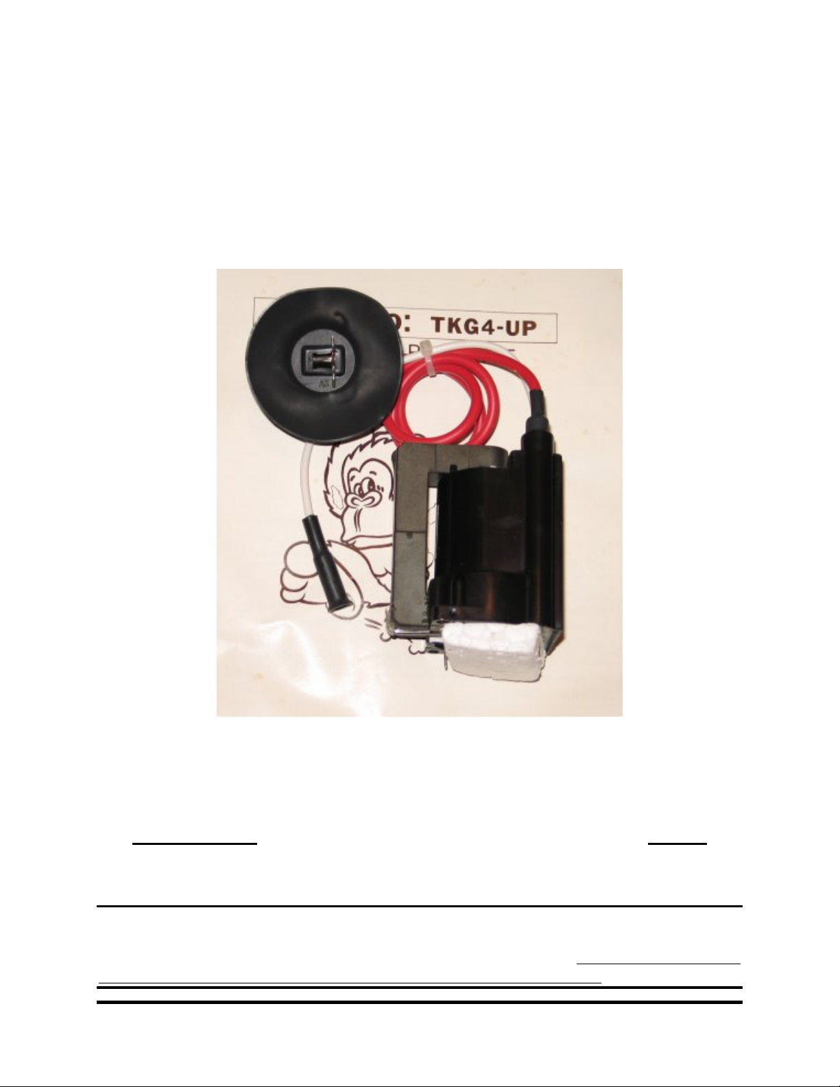
Cinelabs Sanyo EZ-20 Flyback
Installation Guide
WARNING: CRT display monitors can produce lethal
voltages. Refer servicing to qualified service personnel.
PLEASE NOTE: This product is intended to be installed following the guidelines contained in
this document, by qualified service personnel. The manufacturer and distributors of this product
will not be held liable for any damage resulting from this product’s use. If you are uncomfortable
with this, you may return the product within seven (7) days, for a full refund.
Revision 1.3
April 28, 2007
Page 2
Revision 1.3 : * RELEASED * Page 2 of 9
4/28/2007
WARRANTY: If properly installed by a qualified service person, this product will be warranted
for a period of ninety (90) days. This period starts on the date of receipt of product, if ordered
directly from Cinelabs, or, from the purchase date on the original receipt, if purchased through an
authorized distributor. Should you ever have to use this warranty, the distributor you purchased
your Flyback from will repair or replace, at their option, the original part. The distributor’s and
Cinelabs’ liability is limited to replacement of the part, and neither party will be responsible for
any damages incidental or consequential to your game or person. This warranty does not cover
“abuse” (physical, environmental, or electrical).
Revision History:
Rev. Date Author Comments
0.1 05/11/2003 Shostak Initial draft
0.2 05/31/2003 Shostak Added content / incorporated feedback
1.0 08/09/2003 Shostak Added TYPE-A / TYPE-B content
1.3 04/28/2007 Shostak Updated to make consistent with later FBT manuals
The most recent revision of this document can be found at:
http://www.cinelabs.com/docs/Sanyo_Install.pdf
Please send comments and/or corrections to: info@cinelabs.com
Terms: By installing this part, you agree to take full responsibility for any damage caused to your
game and/or person, you may incur, due to lack of experience or expertise, lack of having the
correct tools, etc. You agree to read the complete installation manual, prior to installing the part,
and complying with all safety advisements and warnings.
This guide is intended to assist in the replacement of the Flyback Transformer (“FBT”) of Sanyo
EZ-20 monitors, when it has been determined the FBT is defective. This guide is not intended to
explain how to troubleshoot or diagnose these monitors.
Copyright © 2003, 2007 Cinelabs, LLC
www.cinelabs.com
Page 3

Revision 1.3 : * RELEASED * Page 3 of 9
4/28/2007
Thank You for purchasing a Cinelabs replacement Flyback
Transformer!
Be sure to read this entire document *before* working on your monitor.
CRT displays are dangerous and potentially lethal. There is risk of physical
injury from the glass CRT and danger of electrocution from high-voltage.
We advise always wearing safety glasses when working on CRT displays, as well
as keeping one hand behind your back when working on a CRT display, energized
or not.
Remember, CRT picture tubes can store a High-Voltage charge for extended
periods of time. Always be sure to discharge the CRT prior to FBT replacement
and follow ALL industry safety practices and procedures, regardless of how
long the display has been turned off. Never make any assumptions.
If you are unsure of how to perform any safety related procedures, or are unsure of
how to safely perform this procedure, please contact a trained service technician to
perform the installation or return the never installed FBT, for a full refund.
Copyright © 2003, 2007 Cinelabs, LLC
www.cinelabs.com
Page 4

Revision 1.3 : * RELEASED * Page 4 of 9
4/28/2007
Helpful Hints:
Cinelabs recommends installation of a cap kit when replacing the Flyback
transformer.
Be sure to check the B+ when performing repairs on the Sanyo monitor. Failure to
do so can result in latent shut-down issues.
If you experience a straight horizontal line (vertical line if the monitor is mounted
in a vertical orientation), be sure to check the monitor’s “Service Mode” switch.
This is a switch mounted on the monitor PCB that will collapse the monitor’s
vertical image. Many people have wasted much time attempting to “fix” this
problem. Don’t be one of them! ;-)
Be advised that under certain input conditions, the Sanyo EZ-20 will blow its
300ma fuse. Most commonly this happens when accidentally driving it with noninverted video. This does not cause any permanent damage to the monitor (other
than to the fuse), but does result in a no-picture, no-high voltage condition.
Tools Required:
• CRT Discharge Tool (HV Probe or equivalent)
• Philips head screw driver
• Flat head screw driver
• Drill with 7/64” or 1/8” drill bit
• Pencil
• Small file
Included Parts:
• One - Flyback Transformer (Type-A)
• Two - 4-40 x 3/8” screws
• Two - 4-40 nuts
Copyright © 2003, 2007 Cinelabs, LLC
www.cinelabs.com
Page 5

Revision 1.3 : * RELEASED * Page 5 of 9
4/28/2007
Removing the old FBT:
1. Determine FBT is defective.
2. Make careful notes as to the connecting wires (yoke, etc.), location of the FBT, etc.,
before working on the monitor.
3. Discharge any residual energy from the CRT, following industry standard CRT
discharge procedures.
4. Disconnect the FBT anode cap from the CRT, following industry standard procedures
(we recommend, at minimum, keeping one hand behind your back).
5. Momentarily short the anode cap to the chassis, to ensure the FBT is discharged.
6. Remove monitor PC board from monitor frame (including the metal HV shield).
7. Find the white FOCUS wire that connects to the neck board. Remove this wire from the
FOCUS ASSEMBLY, leaving it attached to the neck board.
Figure 1: Focus Assembly and (original) FBT
8. Remove the screw securing the FBT to the heatsink, located next to the HOT (see figure
2).
Figure 2: Flyback Retaining Screw
Copyright © 2003, 2007 Cinelabs, LLC
www.cinelabs.com
Page 6

Revision 1.3 : * RELEASED * Page 6 of 9
4/28/2007
9. Unsolder old FBT from PC board.
10. Remove old FBT and Focus Assembly from monitor PC board.
Preparing the new FBT:
1. We suggest you mark the original connections on the Focus Assembly with a marking pen
(see figure 3).
2. Unsolder the black wire from old FBT (pin 12).
3. Unsolder the red wire from old FBT (pin 4).
Figure 3: Example marking (Your Focus Assembly may be wired differently).
4. Disconnect the connectorized wwhhiittee wire from Focus Assembly on the FBT (see figure 4).
Figure 4: FBT to FA Connection
5. Remove the screw securing the Focus Assembly to the old FBT.
6. Remove Focus Assembly from old FBT.
7. Solder the black wire from the Focus Assembly to new FBT (pin 12).
8. Solder the red wire from the Focus Assembly to new FBT (pin 4).
Copyright © 2003, 2007 Cinelabs, LLC
www.cinelabs.com
Page 7

Revision 1.3 : * RELEASED * Page 7 of 9
4/28/2007
9. Connect the white wire from the new FBT to the Focus Assembly. (Be sure to connect it to
the proper terminal as marked in step 3. Connecting to the wrong terminal may damage
monitor).
NOTE: The red and black wires are solid, and break easily.
Figure 5: New FBT to FA Connections
Installing the new FBT:
1. Insert the new FBT into the monitor PC board.
2. Route the red wire from the FBT to the Focus Assembly through the small, notched
channel in the bottom of the FBT (see figure 5).
3. Route the black wire through the large opening directly next to pin 12 on the bottom of
the FBT (see figure 5).
4. Solder FBT in place.
5. Reattach the connectorized white focus wire (coming from the neck board) to the Focus
Assembly. (Be sure to connect it to the proper terminal as marked in step 3 of the
“Preparing the new FBT” section. Connecting to the wrong terminal may damage
monitor).
6. Reinstall the monitor chassis onto the monitor frame.
7. Discharge the CRT’s anode connection (i.e. on the tube itself) (yes, again).
Copyright © 2003, 2007 Cinelabs, LLC
www.cinelabs.com
Page 8

Revision 1.3 : * RELEASED * Page 8 of 9
4/28/2007
8. Reattach all connections (yoke, CRT back/neck PCB, degaussing coil, etc.)
9. Connect the FBT anode cap to the CRT anode connection.
Mounting the Focus Assembly:
The original Sanyo EZ-20 FBT had the Focus Assembly mounted on the FBT case.
You will need to mount the Focus Assembly in a new location.
1. Hold the Focus Assembly up to the flange of the chassis heat sink and mark hole
locations with a pencil.
Figure 6: Marking FA Mounting Holes
2. Move the Focus Assembly out of the way, and drill two holes where you marked the
chassis heat sink, with a 7/64” or 1/8” drill bit.
3. After drilling, remove all metal shards around the holes with a small file.
4. Remove all metal debris with compressed air, a vacuum cleaner, or equivalent.
5. Mount the Focus Assembly to the chassis heat sink, using the two sets of supplied 4-40
screws and nuts.
Figure 7: FA Properly Secured to Chassis
Copyright © 2003, 2007 Cinelabs, LLC
www.cinelabs.com
Page 9

Revision 1.3 : * RELEASED * Page 9 of 9
4/28/2007
Install the HV Shield:
1. Place the metal HV shield close to FBT and mark the area where the Focus Assembly is
located.
2. Make a cut out in the metal HV shield for the Focus Assembly with small metal cutters.
Figure 8: HV Shield
WARNING: Be careful, as the cut metal is very sharp!
3. File or fold any sharp edges of the cut out.
4. Re-install the metal HV shield and screw down.
Figure 9: Completed Installation
Congratulations. FBT Installation is complete!
Reassemble monitor in reverse of disassembly.
(After a 20 minute warm-up, be sure to check the B+)
Copyright © 2003, 2007 Cinelabs, LLC
www.cinelabs.com
 Loading...