

Page 1
Power Supply ICs, LED Driver ICs
2008-6
Page 2
For both analog and digital systems,
SANYO multifunction regulator IC products,
support our customers' creation of the new wave
of next generation in electronic products
by providing extensive functionality
and high reliability for all electronic devices.
Contemporary electronic equipment requires a wide range of high-level technologies to remain viable in today's
competitive market. For example, cell phones require technologies that achieve stable operation at low input
voltages, improved efficiency, and further miniaturization in the power supply system. Similarly, digital home
appliances not only requires low-power/low-voltage operation and improved efficiency, but also low power
consumption in standby mode to meet energy usage requirements and the ability to meet high-frequency radiation
standards.
We at SANYO Semiconductor makes a point of grasping these needs as early as possible and developing ICs
contributing to achieve improved system development and high level of integration based on our rich experience in
general-purpose product technologies.
* The outer dimensions in this brochure are only reference values (typical values). They may change without notice due to modifications or improvements.
At the time of product design or delivery, be sure to check with the delivery specifications or external dimension drawings of each device.
Any and all SANYO Semiconductor Co.,Ltd. products described or contained herein are, with regard to "standard
application", intended for the use as general electronics equipment (home appliances, AV equipment, communication
device, office equipment, industrial equipment etc.). The products mentioned herein shall not be intended for use for any
"special application" (medical equipment whose purpose is to sustain life, aerospace instrument, nuclear control device,
burning appliances, transportation machine, traffic signal system, safety equipment etc.) that shall require extremely high
level of reliability and can directly threaten human lives in case of failure or malfunction of the product or may cause harm
to human bodies, nor shall they grant any guarantee thereof. If you should intend to use our products for applications
outside the standard applications of our customer who is considering such use and/or outside the scope of our intended
standard applications, please consult with us prior to the intended use. If there is no consultation or inquiry before the
intended use, our customer shall be solely responsible for the use.
Specifications of any and all SANYO Semiconductor Co.,Ltd. products described or contained herein stipulate the
performance, characteristics, and functions of the described products in the independent state, and are not guarantees of
the performance, characteristics, and functions of the described products as mounted in the customer's products or
equipment. To verify symptoms and states that cannot be evaluated in an independent device, the customer should always
CONTENTS
♦
Product Lineup
• DC-DC Converter (Control) ICs ------------------ 3
• DC-DC Converter (Control) ICs ------------------ 3
[Synchronous Rectification Type]
• AC-DC Converter (Control) ICs ------------------ 4
• Power Supply ICs -------------------------------- 4
for Single Lens Reflex Digital Cameras
• Power Supply ICs for Surveillance Cameras --- 4
• Power Supply ICs for Panels -------------------- 4
• System Power Supply ICs ----------------------- 5
(for Portable Electronic Devices)
• System Power Supply ICs ----------------------- 5
(for AV Electronic Devices)
1 2
•
Series Power Supply ICs -----------------------
•
Power Supply Switching ICs ----------------------
•
Power ICs with a Watchdog Timer Function -----
•
Dual-Protection ICs --------------------------------
•
Dual-Protection ICs ----------------------------
6 to 9
10, 11
(for Rechargeable Lithium-ion Batteries)
•
Rechargeable Battery Charge Control ICs -------
•
Dedicated Reset Function ICs --------------------
•
LED Driver ICs --------------------------------------
9
10
10
11
11
11
evaluate and test devices mounted in the customer's products or equipment.
SANYO Semiconductor Co.,Ltd. assumes no responsibility for equipment failures that result from using products at values
that exceed, even momentarily, rated values (such as maximum ratings, operating condition ranges, or other parameters)
listed in products specifications of any and all SANYO Semiconductor Co.,Ltd. products described or contained herein.
SANYO Semiconductor Co.,Ltd. strives to supply high-quality high-reliability products, however, any and all semiconductor
products fail or malfunction with some probability. It is possible that these probabilistic failures or malfunction could give
rise to accidents or events that could endanger human lives, trouble that could give rise to smoke or fire, or accidents that
could cause damage to other property. When designing equipment, adopt safety measures so that these kinds of
accidents or events cannot occur. Such measures include but are not limited to protective circuits and error prevention
circuits for safe design, redundant design, and structural design.
In the event that any or all SANYO Semiconductor Co.,Ltd. products described or contained herein are controlled under
any of applicable local export control laws and regulations, such products may require the export license from the
authorities concerned in accordance with the above law.
No part of this publication may be reproduced or transmitted in any form or by any means, electronic or mechanical,
including photocopying and recording, or any information storage or retrieval system, or otherwise, without the prior written
consent of SANYO Semiconductor Co.,Ltd.
Any and all information described or contained herein are subject to change without notice due to product/technology
improvement, etc. When designing equipment, refer to the "Delivery Specification" for the SANYO Semiconductor Co.,Ltd.
product that you intend to use.
Information (including circuit diagrams and circuit parameters) herein is for example only; it is not guaranteed for volume
production.
Upon using the technical information or products described herein, neither warranty nor license shall be granted with
regard to intellectual property rights or any other rights of SANYO Semiconductor Co.,Ltd. or any third party. SANYO
Semiconductor Co.,Ltd. shall not be liable for any claim or suits with regard to a third party's intellectual property rights
which has resulted from the use of the technical information and products mentioned above.
Page 3
Product Lineup
Product Lineup
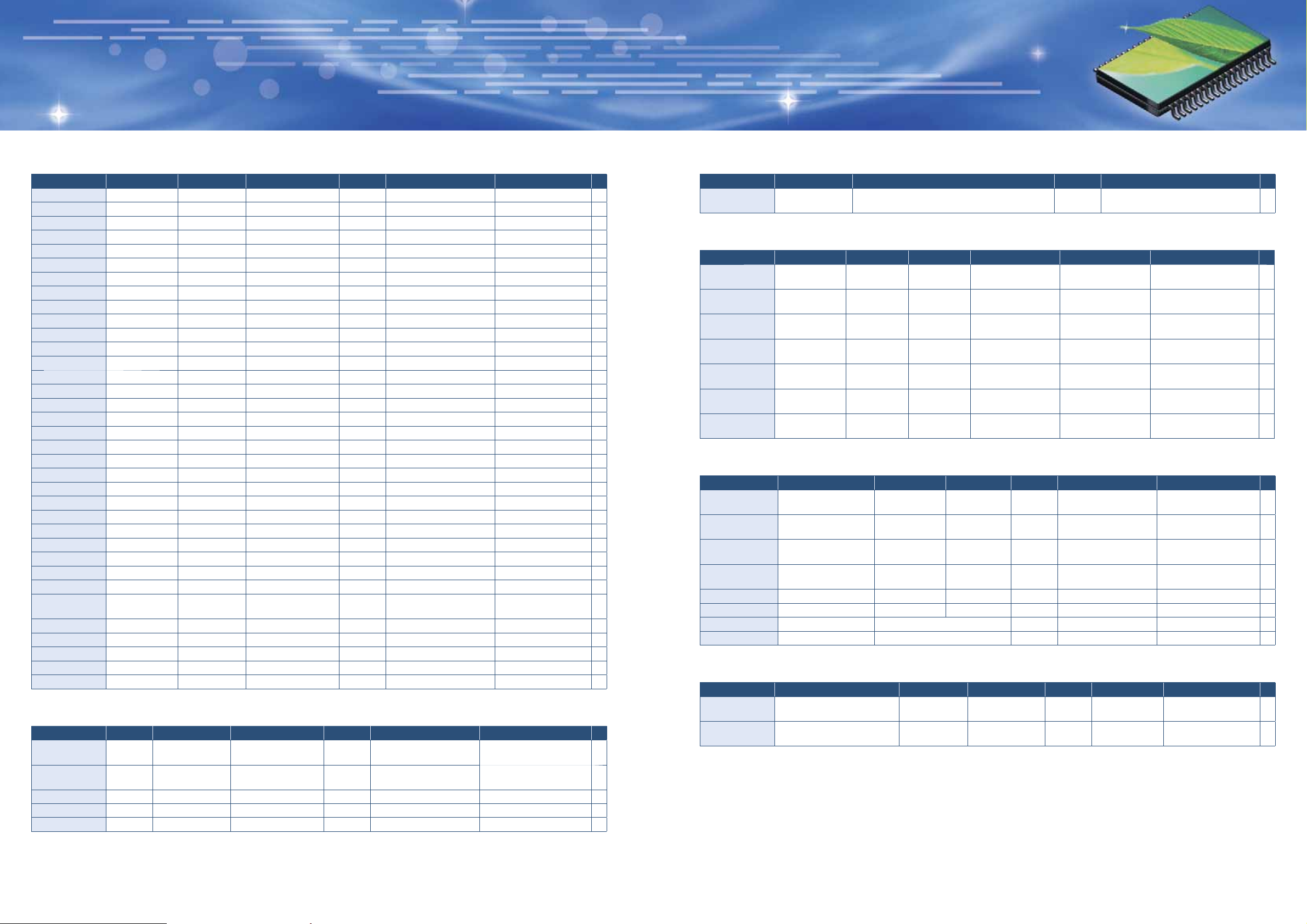
DC-DC Converter (Control) ICs
Type No. Type Input voltage Output voltage
LA5660M Step up 1.8V to 14V
●
LV5803M Step down 4.5V to 18V
❈
LV5807MA Step down 4.5V to 18V
●
LA5724M Step down 4.5V to 28V
●
LA5744 Step down 4.5V to 28V
●
LA5744MP Step down 4.5V to 28V
●
LA5744TP Step down 4.5V to 28V
●
LA5774 Step down 4.5V to 28V
●
LA5774MP Step down 4.5V to 28V
●
LA5779 Step down 4.5V to 28V
●
LA5779MP Step down 4.5V to 28V
●
LA5779N Step down 4.5V to 28V
●
LA5734MP Step down 4.5V to 32V
●
LA5735M Step down 4.5V to 32V
❈
LA5755 Step down 4.5V to 32V
❈
LA5756 Step down 4.5V to 32V
❈
LV5745GP Step down 4.5V to 6V
●
LV5781 Step down 4.5V to 6V
LA5771MP Step down 5.5V to 28V 3.3V/3A 1ch Built in SMP5
●
LA5771 Step down 5.5V to 32V 3.3V/3A 1ch Built in 220-5H
LA5772MP Step down 7V to 28V 5V/3A 1ch Built in SMP5
●
LA5772 Step down 7V to 32V 5V/3A 1ch Built in 220-5H
❈
LV5746V Step down 8V to 22V
●
LA5777 Step down 8V to 28V 5V/3A 1ch Built in 220-5H
●
LA5777MP Step down 8V to 28V 5V/3A 1ch Built in SMP5
❈
LV5806MA Step down 8V to 28V
❈
LV5808M Step down 8V to 28V
●
LV5743V Step down 8V to 33V
LA5664M Step up/down 4V to 5.6V 5V/250mA 1ch Built in MFP14S(225mil)
LV5051T
●
TN5D41A Step down 10V to 40V 5V/5A 1ch Built in (PMOS) TO-220FI5H-HB
❈
TN8D41A Step down 10V to 40V 5V/8A 1ch Built in (PMOS) TO-220FI5H-HB
●
TN5D51A Step down 20V to 48V 12V/5A 1ch Built in (PMOS) TO-220FI5H-HB
❈
TN8D51A Step down 20V to 48V 12V/8A 1ch Built in (PMOS) TO-220FI5H-HB
❈
TN5D61A Step down 30V to 48V 24V/5A 1ch Built in (PMOS) TO-220FI5H-HB
Step up/down+
Linear regulator
1.5V to 4.4V
2V to 8.0V
Programmable externally
Programmable externally
Programmable externally
Programmable externally/0.6A
Programmable externally/3A
Programmable externally/3A
Programmable externally/3A
Programmable externally/3A
Programmable externally/3A
Programmable externally/3A
Programmable externally/3A
Programmable externally/3A
Programmable externally/3A
Programmable externally/0.6A
Programmable externally
Programmable externally
Programmable externally
Programmable externally
Programmable externally
Programmable externally
Programmable externally
Programmable externally
2.5V (Step up/down)
2.8V/3.9A (Linear)
Channels
1ch External (NPN or NMOS) MFP8(225mil)
1ch Built in MFP8(225mil)
1ch Built in SOP8J(200mil)
1ch Built in MFP8(225mil)
1ch Built in 220-5HK
1ch Built in SMP5
1ch Built in TP5HFA
1ch Built in 220-5H
1ch Built in SMP5
1ch Built in 220-5H
1ch Built in SMP5
1ch Built in 220-5HK
1ch Built in SMP5
1ch Built in MFP8(225mil)
1ch Built in TO220
1ch Built in TO220
3ch External (PMOS) VCT28(3.0×3.0)
1ch Built in HSSOP14(225mil)
2ch External (PMOS) SSOP20(225mil)
1ch Built in SOP8J(200mil)
1ch Built in MFP8(225mil)
2ch External (PMOS) SSOP16(225mil)
3ch Built in TSSOP24(225mil)
Power stages Package P
DC-DC Converter (Control) ICs [Synchronous Rectifi cation Type]
Type No. Type Input voltage Output voltage
●
LV5044V
●
LV5050V
❈
LV5747TT
❈
LV5749V
❈
LV5741
Step down
Step down
Step down
Step down
Step down
7.5V to 16V
4.5V to 6V
7.5V to 16V
4.5V to 6V
8V to 42V
8V to 42V
8V to 42V
Programmable externally
Programmable externally
Programmable externally
Programmable externally
Programmable externally
Channels
2ch External (NMOS) SSOP30(275mil)
1ch External (NMOS) SSOP20(225mil)
1ch External (NMOS) MSOP12(150mil)
1ch External (NMOS) SSOP16(225mil)
1ch External (NMOS) DIP16(300mil)
Power stages Package P
: New products and
●
: Development
❈
: New products and
●
: Development
❈
AC-DC Converter (Control) ICs
Type No. Package Functions
13
LA5648 DIP8(300mil)
RCC/separately-excited fl y-back AC-DC
converter controller
Power Supply ICs for Single Lens Refl ex Digital Cameras
Type No. Type
LA5680T
12
12
12
12
12
12
12
12
12
12
12
14
14
14
14
14
15
●
LA5683T
LA5679T
LA5669T
●
LV5603T
❈
LV5655
●
LV5604T
Power Supply ICs for Surveillance Cameras
Type No. Type Input voltage
●
LA5795T Charge pump step-up 13.5V to 28V
●
LA5797M Charge pump step-up 7.5V to 28V
❈
LV5606LP
❈
LV5606V
●
LV5608LP
❈
LV56081GP
●
LV5609LP V driver for CCD
●
LV5609V V driver for CCD
Power Supply ICs for Panels
Type No. Type Input voltage Output voltage
❈
LA5661M Backlight inverter 1.8V to 14V
●
LA5663V Phase control voltage inverter 4.5V to 23V
Mixed step up/
step down
Mixed step up/
step down
Mixed step up/
step down
Multiple power
supply
Multiple power
supply
Multiple power
supply
Multiple power
supply
± Charge pump step-up
± Charge pump step-up
± Charge pump step-up
± Charge pump step-up
Input voltage
1.5V to 12V
1.8V to 8V
1.8V to 11V
1.8V to 11V
3V to 15V
3V to 15V
3V to 15V
Output voltage Channels
Programmable
externally
Programmable
externally
Programmable
externally
Programmable
externally
Programmable
externally
Programmable
externally
Programmable
externally
3V to 3.45V
3V to 3.45V
3V to 3.45V 15V, -7.5V 2ch Built in VCT24(3.5×3.5)
3V to 3.45V 15V, -5.5V 2ch Built in VCT24(3.5×3.5)
Ratings are listed on separate datasheet
Ratings are listed on separate datasheet
6ch
(Step up 4, down 2)
4ch
(Step up 2, down 2)
3ch
(Step up 1, down 2)
3ch External TSSOP36(275mil)
6ch
(Step up 2, down 4)
3ch
(Step up 1, down 2)
8ch
(Step up 3, down 5)
Output voltage
Programmable
externally
Programmable
externally
Programmable
externally
Programmable
externally
Programmable
externally
Programmable
externally (Current)
Channels
1ch Built in MSOP10(150mil)
1ch
2ch Built in VQLP32(4.0×4.0)
2ch Built in SSOP30(275mil)
5ch Built in VCT24(3.5×3.5)
5ch Built in SSOP20(225mil)
VCC(V)
30
UVLO, primary side PbyPOCP,
secondary side timer type OCP
Features P
●
Power stages Package P
External
(NPN, PNP
or NMOS, PMOS)
External
(NPN, PNP
or NMOS, PMOS)
External
(NPN, PNP
or NMOS, PMOS)
External TQFP48J(7×7)
External SSOP24(225mil)
External TQFP64J(7×7)
TQFP48J(7×7)
TSSOP36(275mil)
TSSOP36(275mil)
●
Power stages Package P
Built in (External diode)
Channels
1ch External MFP10S(225mil)
1ch External SSOP24(275mil)
Power stages Package P
MFP8(225mil)
●
16
: New products and
: Development
❈
17
18
19
: New products and
: Development
❈
: New products and
: Development
❈
3 4
Page 4
System Power Supply ICs
Regulator output voltage/current Absolute maximum ratings
Type No.
LA5160AM
LV5105FN
●
LV5103LP
1234
5V/
100mA
2.8V/
2.6V/
2.85V/
150mA
100mA
50mA
1234
1.5V/
2.85V/
2.85V/
30mA
200mA
150mA
5678
3.3V/
1.5V/
1.8V/
150mA
200mA
150mA
System Power Supply ICs
Regulator output voltage/current
Type No.
12345
3.3V/
3.3V/
LA5632
LA5643
LA5624H
LA5635H
LA5613
LA5601
LA5617
LA5605
LA5606N
60mA
3.5V/
150mA
12345
5V/
50mA
678910
8V/
100mA
11 12 13 14
OP1-C/
10mA
12345
5V/
50mA
678910
8V/
100mA
11 12 13 14
OP1-C/
10mA
5.1V/
700mA
5.2V/
250mA
7.5V/
500mA
7.5V/
500mA
15.7V/
350mA
150mA
5V/
1000mA
10V/*
5V/
100mA
OP2-C/
10mA
10V/*
5V/
100mA
OP2-C/
10mA
SW/
300mA
3.4V/
10mA
−7.5V/
−500mA
9V/
60mA
12V/
200mA
5V/
1000mA
5V/
100mA
8V/
100mA
5V/
300mA
OP3-C/
10mA
8V/
200mA
5V/
300mA
OP3-C/
10mA
5V/
10mA
9V/
150mA
(for Portable Electronic Devices)
Total power
dissipation
(V)
40 0.8
(W)
1.1*
Package
MFP8(225mil)
VQFN48(7×7)
VQLP40(5.0×5.0)
3V/
50mA
3.1V/
450mA
1.2V/
500mA
Input
voltage
5.9 0.44
3.2 to 4.5
(for AV Electronic Devices)
Absolute maximum
ratings
Package
(W)
HSOP28HC
(375mil)
HSOP28HC
(375mil)
DIP10S
(300mil)
5V/
100mA
8V/
30mA
SW/
100mA
OP4-C/
10mA
8V/
30mA
SW/
100mA
OP4-C/
10mA
5V/
500mA
8V/
150mA
SW/
100mA
8V/
150mA
SW/
500mA
Input
voltage
Total power
dissipation
(V)
14 2.3 SIP12H
14 2.0 SIP13H
24 2.01
24 2.01
14 1.7 SIP10F
15 1.0
±18 2.0 SIP10F
24 2.0 SIP13H
35 4.3 SIP14H
: New products
●
Functions/Features P
Low consumption current at output-off time with
built-in ON/OFF function.
Built-in reset circuit × 2, 3-color LED driver, front
LED driver, and microphone bias output.
Built-in step-down DC-DC converter × 1, series
regulator × 8, and short-circuit protection circuit
*Ratings mounted on board: 40mm×50mm×0.8mm,
Glass epoxy 4-layer (2S2P) board
Functions/Features
ON/OFF
function
Reset
output
●●
●●
●●
●
●●
●
●
With power ON/OFF
detection circuit.
●
10V regulator (when used
with external PNP transistor)
with standby function (on/off
control).
* Within ASO of external TR
10V regulator (when used
with external PNP transistor)
with standby function (on/off
control).
* Within ASO of external TR
11.3V/0.3A ripple fi lter
switching regulator control
amplifi er built in.
Built-in driver
±Voltage tracking regulator
Built-in AC standby and
power detection functions.
Notes
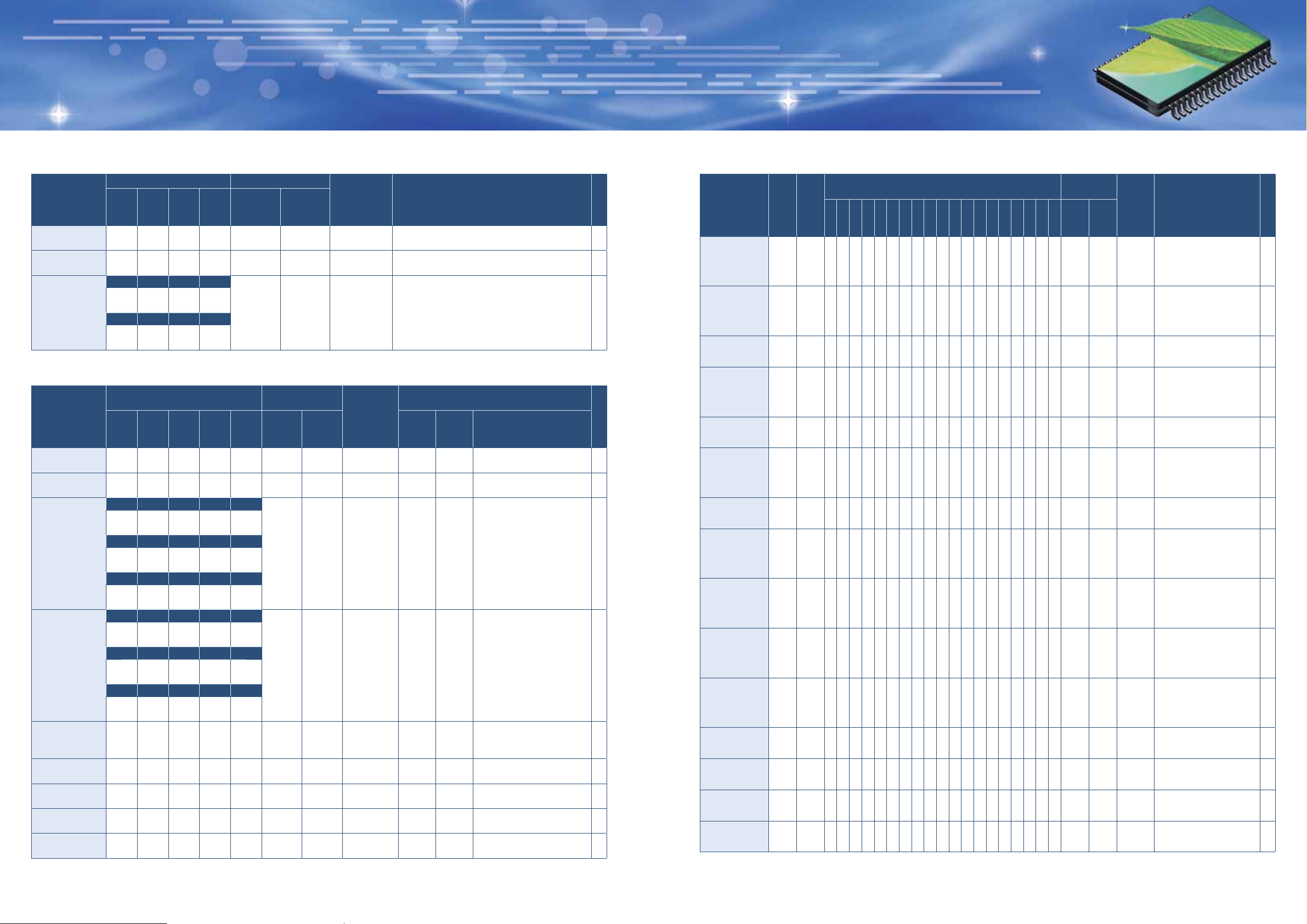
Series Power Supply ICs
Output
Positive
voltage
Positive
voltage
Positive
voltage
Positive
voltage
Positive
voltage
Positive
voltage
Positive
voltage
Positive
voltage
Positive
voltage
Positive
voltage
Positive
voltage
Positive
voltage
Positive
voltage
Positive
voltage
Positive
voltage
Current
1.8 2 2.5 3 3.3 3.4 3.5 4 5 6 7 8 9 10 12 15 18 20 24
(A)
0.06
0.06
0.06
0.06
0.06
0.06
0.06
0.06
0.06
0.06
0.06
0.5
0.5
0.5
0.5
●
●
●
Type No. Type
LA5002M
LA5003
LA5003M
LA5004
P
LA5004M
LA5005
LA5005M
LA5006M
LA5008M
LA5009M
LA5010M
L88M05T
L88M06T
L88M09T
L88M12T
Output voltage (V)
●
●
●
●
●
●
●
●
●
●
●
●
Absolute
maximum ratings
Input
voltage
(V)
12 0.3
12 0.56 SIP4H
12 0.3
12 0.56 SIP4H
12 0.3
12 0.56 SIP4H
12 0.3
16 0.3
16 0.3
16 0.3
16 0.3
18 1.0 TP3H
18 1.0 TP3H
18 1.0 TP3H
18 1.0 TP3H
Package
Total power
dissipation
(W)
MFP8
(225mil)
MFP8
(225mil)
MFP8
(225mil)
MFP8
(225mil)
MFP8
(225mil)
MFP8
(225mil)
MFP8
(225mil)
MFP8
(225mil)
Features P
2V low-saturation voltage
regulator, 2V output voltage,
60mA output current,
low-saturation (0.2V typ) series
regulator, RF noise suppression
3V low-saturation voltage
regulator, 3V output voltage,
60mA output current,
low-saturation (0.2V typ) series
regulator, RF noise suppression
3V low-saturation voltage
regulator, SOP (MFP)
version of LA5003
4V low-saturation voltage
regulator, 4V output voltage,
60mA output current,
low-saturation (0.2V typ) series
regulator, RF noise suppression
4V low-saturation voltage
regulator, SOP (MFP)
version of LA5004
5V low-saturation voltage
regulator, 5V output voltage,
60mA output current,
low-saturation (0.2V typ) series
regulator, RF noise suppression
5V low-saturation voltage
regulator, SOP (MFP)
version of LA5005
6V low-saturation voltage
regulator, 6V output voltage,
60mA output current,
low-saturation (0.2V typ) series
regulator, RF noise suppression
8V low-saturation voltage
regulator, 8V output voltage,
60mA output current,
low-saturation (0.2V typ) series
regulator, RF noise suppression
9V low-saturation voltage
regulator, 9V output voltage,
60mA output current,
low-saturation (0.2V typ) series
regulator, RF noise suppression
10V low-saturation voltage
regulator, 10V output voltage,
60mA output current,
low-saturation (0.2V typ) series
regulator, RF noise suppression
5V low-saturation voltage regulator,
5V output voltage, 0.5A output current,
0.4V (typ) minimum I/O voltage drop
6V low-saturation voltage regulator,
6V output voltage, 0.5A output current,
0.4V (typ) minimum I/O voltage drop
9V low-saturation voltage regulator,
9V output voltage, 0.5A output current,
0.4V (typ) minimum I/O voltage drop
12V low-saturation voltage regulator,
12V output voltage, 0.5A output current,
0.4V (typ) minimum I/O voltage drop
Continued on next page.
5 6
Page 5
Series Power Supply ICs
Output
Positive
voltage
Positive
voltage
Positive
voltage
Positive
voltage
Positive
voltage
Positive
voltage
Positive
voltage
Positive
voltage
Positive
voltage
Positive
voltage
Positive
voltage
Positive
voltage
Positive
voltage
Current
(A)
0.5
0.5
0.5
0.5
0.5
0.5
0.5
0.5
0.5
0.5
1.0
1.0
1.0
Type No. Type
L88M33T
L88M35T
L88MS04T
L88MS05T
L88MS06T
L88MS08T
L88MS09T
L88MS12T
L88MS33T
L88MS34T
L88R05C
L88R05D
L88R05E
Continued from preceding page.
Output voltage (V)
1.8 2 2.5 3 3.3 3.4 3.5 4 5 6 7 8 9 10 12 15 18 20 24
●
●
●
●
●
●
●
●
●
●
●
●
●
Absolute
maximum ratings
Input
voltage
(V)
18 1.0 TP3H
18 1.0 TP3H
18 1.0 TP5H
18 1.0 TP5H
18 1.0 TP5H
18 1.0 TP5H
18 1.0 TP5H
18 1.0 TP5H
18 1.0 TP5H
18 1.0 TP5H
18 2.75 220-5H
18 2.75 220-5H
18 2.75 220-5H
Package
Total power
dissipation
(W)
Features
3.3V low-saturation voltage
regulator, 3.3V output voltage,
0.5A output current, 0.4V (typ)
minimum I/O voltage drop
3.5V low-saturation voltage
regulator, 3.5V output voltage,
0.5A output current, 0.4V (typ)
minimum I/O voltage drop
4V low-saturation voltage
regulator with strobe pin,
4V output voltage, 0.5A output
current, strobe pin, 0.4V (typ)
minimum I/O voltage drop
5V low-saturation voltage
regulator with strobe pin,
5V output voltage, 0.5A output
current, strobe pin, 0.4V (typ)
minimum I/O voltage drop
6V low-saturation voltage
regulator with strobe pin,
6V output voltage, 0.5A output
current, strobe pin, 0.4V (typ)
minimum I/O voltage drop
8V low-saturation voltage
regulator with strobe pin,
8V output voltage, 0.5A output
current, strobe pin, 0.4V (typ)
minimum I/O voltage drop
9V low-saturation voltage
regulator with strobe pin,
9V output voltage, 0.5A output
current, strobe pin, 0.4V (typ)
minimum I/O voltage drop
12V low-saturation voltage
regulator with strobe pin,
12V output voltage, 0.5A output
current, strobe pin, 0.4V (typ)
minimum I/O voltage drop
Low-saturation voltage regulator
with on/off function, 3.3V output
voltage, 0.5A output current,
strobe pin, 0.4V (typ) minimum
I/O voltage drop
3.4V low-saturation voltage
regulator with strobe pin, 3.4V
output voltage, 0.5A output
current, strobe pin, 0.4V (typ)
minimum I/O voltage drop
4.5V low-saturation voltage
regulator with reset pin,
5V output voltage, 1A output
current, reset pin, 0.5V (typ)
minimum I/O voltage drop
4.2V low-saturation voltage
regulator with reset pin,
5V output voltage, 1A output
current, reset pin, 0.5V (typ)
minimum I/O voltage drop
3.9V low-saturation voltage
regulator with reset pin,
5V output voltage, 1A output
current, reset pin, 0.5V (typ)
minimum I/O voltage drop
P
Series Power Supply ICs
Output
Positive
voltage
Positive
voltage
Positive
voltage
Positive
voltage
Positive
voltage
Positive
voltage
Positive
voltage
Positive
voltage
Positive
voltage
Positive
voltage
Positive
voltage
Positive
voltage
Positive
voltage
Positive
voltage
Positive
voltage
Positive
voltage
Positive
voltage
Current
(A)
0.15
0.5
0.5
0.5
0.5
0.5
0.5
0.5
0.5
0.5
0.5
0.5
0.5
1.0
1.0
1.0
1.0
Type No. Type
L78LR05
L78M05T
L78M06T
L78M07T
L78M08T
L78M09T
L78M10T
L78M12T
L78M15T
L78M18T
L78M20T
L78M24T
L78MG
L780S05
L780S08
L780S09
L780S10
Output voltage (V)
1.8 2 2.5 3 3.3 3.4 3.5 4 5 6 7 8 9 10 12 15 18 20 24
●
●
●
●
●
●
●
●
●
●
●
●
●
●
●
Absolute
maximum ratings
Input
Total power
voltage
dissipation
(V)
(W)
25 1.0 TP5H
35 1.0 TP3H
35 1.0 TP3H
35 1.0 TP3H
35 1.0 TP3H
35 1.0 TP3H
35 1.0 TP3H
35 1.0 TP3H
35 1.0 TP3H
35 1.0 TP3H
35 1.0 TP3H
35 1.0 TP3H
●
35 1.2 SIP4H
35 1.75 220-5H
35 1.75 220-5H
35 1.75 220-5H
35 1.75 220-5H
Package
Features
5V voltage regulator with reset
pin, 5V output voltage, 150mA
output current, reset pin
5V 0.5A 3-pin voltage regulators,
5V output voltage, 500mA output
current, 1.0W power dissipation
6V 0.5A 3-pin voltage regulators,
6V output voltage, 500mA output
current, 1.0W power dissipation
7V 0.5A 3-pin voltage regulators,
7V output voltage, 500mA output
current, 1.0W power dissipation
8V 0.5A 3-pin voltage regulators,
8V output voltage, 500mA output
current, 1.0W power dissipation
9V 0.5A 3-pin voltage regulators,
9V output voltage, 500mA output
current, 1.0W power dissipation
10V 0.5A 3-pin voltage regulators,
10V output voltage, 500mA output
current, 1.0W power dissipation
12V 0.5A 3-pin voltage regulators,
12V output voltage, 500mA output
current, 1.0W power dissipation
15V 0.5A 3-pin voltage regulators,
15V output voltage, 500mA output
current, 1.0W power dissipation
18V 0.5A 3-pin voltage regulators,
18V output voltage, 500mA output
current, 1.0W power dissipation
20V 0.5A 3-pin voltage regulators,
20V output voltage, 500mA output
current, 1.0W power dissipation
24V 0.5A 3-pin voltage regulators,
24V output voltage, 500mA output
current, 1.0W power dissipation
Variable type 4-pin 500mA
constant voltage power
supply, 35V/500mA, Pd: 1.2W
1A general-purpose voltage
regulator, 5V output voltage,
1A output current, strobe
pin, thermal protection and
overcurrent limiter circuits
1A general-purpose voltage
regulator, 8V output voltage,
1A output current, strobe
pin, thermal protection and
overcurrent limiter circuits
1A general-purpose voltage
regulator, 9V output voltage,
1A output current, strobe
pin, thermal protection and
overcurrent limiter circuits
1A general-purpose voltage
regulator, 10V output voltage,
1A output current, strobe
pin, thermal protection and
overcurrent limiter circuits
Continued on next page.
P
7 8
Page 6

Series Power Supply ICs
Type No. Type
L780S12
L780S15
L780S18
L78MR05
L78MR06
L78MR08
L78MR12
L78MS05J
L78MS05JSMP
L79M05T
L79M06T
L79M08T
L79M09T
L79M10T
L79M12T
Positive
voltage
Positive
voltage
Positive
voltage
Positive
voltage
Positive
voltage
Positive
voltage
Positive
voltage
Positive
voltage
Positive
voltage
Negative
voltage
Negative
voltage
Negative
voltage
Negative
voltage
Negative
voltage
Negative
voltage
Continued from preceding page.
Output
Current
1.8 2 2.5 3 3.3 3.4 3.5 4 5 6 7 8 9 10 12 15 18 20 24
(A)
1.0
1.0
1.0
0.5
0.5
0.5
0.5
0.5
0.5
0.5
0.5
0.5
0.5
0.5
0.5
Output voltage (V)
●
●
●
●
●
●
●
●
●
●
Absolute
maximum ratings
Input
voltage
(V)
●
●
●
●
●
35 1.75 220-5H
35 1.75 220-5H
35 1.75 220-5H
35 1.75 220-5H
35 1.75 220-5H
35 1.75 220-5H
35 1.75 220-5H
35 1.75 220-5H
35 2.0 SMP5
-35 1.0 TP3H
-35 1.0 TP3H
-35 1.0 TP3H
-35 1.0 TP3H
-35 1.0 TP3H
-35 1.0 TP3H
Package
Total power
dissipation
(W)
Features
1A general-purpose voltage
regulator, 12V output voltage,
1A output current, strobe
pin, thermal protection and
overcurrent limiter circuits
1A general-purpose voltage
regulator, 15V output voltage,
1A output current, strobe
pin, thermal protection and
overcurrent limiter circuits
1A general-purpose voltage
regulator, 18V output voltage,
1A output current, strobe
pin, thermal protection and
overcurrent limiter circuits
5V voltage regulator with
reset pin, 5V output voltage,
0.5A output current
6V voltage regulator with
reset pin, 6V output voltage,
0.5A output current
8V voltage regulator with
reset pin, 8V output voltage,
0.5A output current
12V voltage regulator with
reset pin, 12V output voltage,
0.5A output current
5V voltage regulator with strobe
pin, 5V output voltage, 0.5A output
current, strobe pin (Features a low
quiescent current of 35μA)
5V voltage regulator with strobe
pin, 5V output voltage, 0.5A output
current, strobe pin (Features a low
quiescent current of 35μA)
-5V 3 pin voltage
regulator (minus output),
−5V/0.5A, Pd: 1.0W
-6V 3 pin voltage
regulator (minus output),
−6V/0.5A, Pd: 1.0W
-8V 3 pin voltage
regulator (minus output),
−8V/0.5A, Pd: 1.0W
-9V 3 pin voltage
regulator (minus output),
−9V/0.5A, Pd: 1.0W
-10V 3 pin voltage
regulator (minus output),
−10V/0.5A, Pd: 1.0W
-12V 3 pin voltage
regulator (minus output),
−12V/0.5A, Pd: 1.0W
Power Supply Switching ICs
Type No. Package
LV5621LP VCT16(2.6×2.6) 2.7 to 4.8 3 3.5 to 5.2 For DSCs and game machines
LV5622LP VCT16(2.6×2.6) 2.7 to 4.8 3 3.5 to 5.2 For DSCs and game machines
LV5625V SSOP16(225mil) 1.45 to 3.4 3 3.5 to 5.2 For DSCs and game machines
VCC1V
Input voltage (V)
2V
CC
CC
3
Applications P
Power ICs with a Watchdog Timer Function
P
Type No.
maximum ratings
Input voltage
(V)
LA5690D 41 0.5 DIP8(300mil)
LA5690S 41 0.5 SIP9
LA5691S 41 0.5 SIP9 Inverted
LA5692D 41 0.5 DIP8(300mil) Inverted
LA5692M 41 0.37
LA5692S 41 0.5 SIP9 Inverted
LA5693AM 41 0.37
LA5693D 41 0.5 DIP8(300mil) Inverted
LA5693M 41 0.5
Absolute
Total power
dissipation
(W)
Package
MFP8(225mil)
MFP8(225mil)
MFP8(225mil)
Function reset
logic output
Noninverted/Inverted
Noninverted/Inverted
Inverted
Inverted
Inverted
5V
Reset
regulator
hold
control
●● ●
●● ●
●● ●
●●
●●
●●
Regulator
output
ON/OFF
●●
●●
●●●
Edge
detection
Watchdog
time typ
(Ct=2μF)
5ms
5ms
5ms
40ms
40ms
40ms
40ms
40ms
40ms
P
21
21
21
Dual-Protection ICs
Absolute maximum ratings
Type No.
Input voltage
(V)
LA5695M 18 0.4 MFP14(225mil)
Dual-Protection ICs
Absolute maximum ratings
Type No.
●
LV5113T -0.3 to +12 0.17 MSOP8(150mil) 2-cell Lithium-ion rechargeable battery protection IC
●
LV5122T -0.3 to +12 0.17 MSOP8(150mil) 2-cell Lithium-ion rechargeable battery protection IC
❈
LV51130T -0.3 to +12 0.17 MSOP8(150mil) 2-cell Lithium-ion rechargeable battery protection IC
●
LV51131T -0.3 to +12 0.17 MSOP8(150mil) 2-cell Lithium-ion rechargeable battery protection IC
❈
LV51132T -0.3 to +12 0.17 MSOP8(150mil) 2-cell Lithium-ion rechargeable battery protection IC
❈
LV51133T -0.3 to +12 0.17 MSOP8(150mil) 2-cell Lithium-ion rechargeable battery protection IC
●
LV51134T -0.3 to +12 0.17 MSOP8(150mil) 2-cell Lithium-ion rechargeable battery protection IC
❈
LV51135T -0.3 to +12 0.17 MSOP8(150mil) 2-cell Lithium-ion rechargeable battery protection IC
❈
LV51136T -0.3 to +12 0.17 MSOP8(150mil) 2-cell Lithium-ion rechargeable battery protection IC
●
LV51137T -0.3 to +12 0.17 MSOP8(150mil) 2-cell Lithium-ion rechargeable battery protection IC
●
LV51138T -0.3 to +12 0.17 MSOP8(150mil) 2-cell Lithium-ion rechargeable battery protection IC
❈
LV5125T -0.3 to +12 0.17 MSOP8(150mil) 2-cell Lithium-ion rechargeable battery protection IC
❈
LV51110T -0.3 to +7 0.35 SOT-23-6 1-cell Lithium-ion rechargeable battery protection IC
❈
LV51110LF -0.3 to +7 0.3 SON5(1.6×2.0) 1-cell Lithium-ion rechargeable battery protection IC
❈
LV51111T -0.3 to +7 0.35 SOT-23-6 1-cell Lithium-ion rechargeable battery protection IC
❈
LV51111LF -0.3 to +7 0.3 SON5(1.6×2.0) 1-cell Lithium-ion rechargeable battery protection IC
❈
LV51112T -0.3 to +7 0.35 SOT-23-6 1-cell Lithium-ion rechargeable battery protection IC
❈
LV51112LF -0.3 to +7 0.3 SON5(1.6×2.0) 1-cell Lithium-ion rechargeable battery protection IC
❈
LV51113T -0.3 to +7 0.35 SOT-23-6 1-cell Lithium-ion rechargeable battery protection IC
❈
20
LV51113LF -0.3 to +7 0.3 SON5(1.6×2.0) 1-cell Lithium-ion rechargeable battery protection IC
❈
LV51114T -0.3 to +7 0.35 SON5(1.6×2.0) 1-cell Lithium-ion rechargeable battery protection IC
Input voltage
(V)
Total power
dissipation
Package Functions/Features P
(W)
Protection ICs for heating/cooling equipment and OA equipment, Builtin abnormal supply voltage detection circuit, driver output with built-in
output delay circuit, can be controlled from 8 input pins.
(for Rechargeable Lithium-ion Batteries)
Total power
dissipation
(W)
Package Functions/Features P
: New products and
●
: Development
❈
Continued on next page.
9 10
Page 7

DC-DC Converter (Control) ICs [Step down]
LA5734MP/71/71MP/72/72MP/
74/74MP/77/77MP/79/79MP
Dual-Protection ICs
(for Rechargeable Lithium-ion Batteries)
Continued from preceding page.
❈: Development
Absolute maximum ratings
Type No.
Input voltage
(V)
❈
LV51114LF -0.3 to +7 0.3 SON5(1.6×2.0) 1-cell Lithium-ion rechargeable battery protection IC
❈
LV51115T -0.3 to +7 0.35 SOT-23-6 1-cell Lithium-ion rechargeable battery protection IC
❈
LV51115LF -0.3 to +7 0.3 SON5(1.6×2.0) 1-cell Lithium-ion rechargeable battery protection IC
❈
LV51116T -0.3 to +7 0.35 SOT-23-6 1-cell Lithium-ion rechargeable battery protection IC
❈
LV51116LF -0.3 to +7 0.3 SON5(1.6×2.0) 1-cell Lithium-ion rechargeable battery protection IC
❈
LV51117T -0.3 to +7 0.35 SOT-23-6 1-cell Lithium-ion rechargeable battery protection IC
❈
LV51117LF -0.3 to +7 0.3 SON5(1.6×2.0) 1-cell Lithium-ion rechargeable battery protection IC
❈
LV51118T -0.3 to +7 0.35 SOT-23-6 1-cell Lithium-ion rechargeable battery protection IC
❈
LV51118LF -0.3 to +7 0.3 SON5(1.6×2.0) 1-cell Lithium-ion rechargeable battery protection IC
❈
LV51119T -0.3 to +7 0.35 SOT-23-6 1-cell Lithium-ion rechargeable battery protection IC
❈
LV51119LF -0.3 to +7 0.3 SON5(1.6×2.0) 1-cell Lithium-ion rechargeable battery protection IC
●
LV51140T -0.3 to +7 0.35 SOT-23-6 1-cell Lithium-ion rechargeable battery protection IC
❈
LV51140LF -0.3 to +7 0.3 SON5(1.6×2.0) 1-cell Lithium-ion rechargeable battery protection IC
●
LV51141T -0.3 to +7 0.35 SOT-23-6 1-cell Lithium-ion rechargeable battery protection IC
❈
LV51141LF -0.3 to +7 0.3 SON5(1.6×2.0) 1-cell Lithium-ion rechargeable battery protection IC
❈
LV51142T -0.3 to +7 0.35 SOT-23-6 1-cell Lithium-ion rechargeable battery protection IC
❈
LV51142LF -0.3 to +7 0.3 SON5(1.6×2.0) 1-cell Lithium-ion rechargeable battery protection IC
Total power
dissipation
(W)
Package Functions/Features P
Rechargeable Battery Charge Control ICs
Type No.
LA5636M
❈
LA5645M
Battery type
Lithium-ion,
nickel-metal hydride
Charger
Absolute
maximum ratings
Input voltage
(V)
14.5 0.36
14.5 0.3 MFP8(225mil)
Total power
dissipation
(W)
MFP10S(225mil)
Package Functions/Features P
Car battery DC/DC converter control IC, output voltage proportional to PWM input signal, for charging lithium-ion batteries
Constant-voltage, constant-current control IC, high precision
reference voltage (1.5V+1%), input offset voltage (2mV max.)
Dedicated Reset Function ICs
: New products and
●
: Development
❈
DC-DC Converter (Control) ICs [Step down]
LA5734MP/71/71MP/72/72MP/
74/74MP/77/77MP/79/79MP
Applications
■
Separately-excited step-down switching regulator
Functions/Features
■
Low-ESR capacitor with increased reliability applicable
●
as the output smoothing capacitor (LA5774/74MP)
High effi ciency
●
4 external parts
●
Built-in reference oscillator (160kHz)
●
Built-in current limiter
●
Built-in thermal shutdown circuit
●
Built-in soft start circuit
●
(LA5771/71MP/72/72MP/74/74MP)
ON/OFF function (LA5734/77/77MP/79/79MP)
●
Type Input voltage Output voltage
Step
down
• 4.5V to 28V (LA5774/74MP/79/79MP)
• 4.5V to 32V (LA5734MP)
• 5.5V to 28V (LA5771MP)
• 5.5V to 32V (LA5771)
• 7V to 28V (LA5772MP)
• 7V to 32V (LA5772)
• 8V to 28V (LA5777/77MP)
• Programmable externally/3A
(LA5734MP/74/74PM/79/79MP)
• 3.3V/3A
(LA5771MP/71)
• 5V/3A
(LA5772MP/72/77/77MP)
unit: mm
(1.6)
10.0
1.2
9.9
(8.8)
4.5
0.9
1.7
15
SANYO: SMP5
Channels
1ch Built in
4.5
1.3
1.5
0.2
2.7
0.4
Power stages
unit: mm
10.4MAX
10.0
3.6
1
(1.6)
2.7
0.9
5
0.8
1.7
Package
• 220-5H
(LA5771/72/74/77/79)
• SMP5
(LA5734MP/71MP/72MP/
74MP/77MP/79MP)
4.5
1.3
15.0
(8.8)
17.8
2.7
0.45
SANYO: 220-5H
21.3
4.5
8.4
23.0
Block Diagram
Example: LA5771 Block Diagram
22
SW
V
IN
Reg.
OCP
OUT
L1
68μH
Absolute
Type No.
maximum ratings
Input voltage
(V)
LA5623M -0.3 to +12 0.3 MFP8(225mil)
Total power
dissipation
(W)
Package Functions/Features P
2-system reset IC with built-in 1.25V, and 4.2V reference voltages,
delay time 25ms, 50ms, 100ms, or 200ms switchable
LED Driver ICs
Type No.
LV5213LP 3.0 to 4.5 3ch VCT16(2.6×2.6) 3-channel LED driver for cell phones
●
LV5215LF 3.0 to 4.5 4ch VQFN12(2.0×2.0) 4-channel LED driver for cell phones
●
LV5217GP 3.0 to 4.5 3ch VCT16(2.6×2.6) 3-channel LED driver for cell phones
Input voltage Channels
Package
Circuit functions and applications
: New products
●
OSC
C1
220μF
23
/35V
P
24
25
C3
1μF
/50V
SS
Comp.
GND
Amp.
Reset
Drive
TSD
VOS
VREF
* For other block diagrams, refer to the datasheet.
D1
SBD
C2
1000μF
/6.3V
R2
R1
11 12
Page 8

DC-DC Converter (Control) ICs [Step down]
LV5803M
DC-DC Converter (Control) ICs [Separately-excited step-down]
TN8D41A/51A, TN5D41A/51A/61A
DC-DC Converter (Control) ICs [Step down]
LV5803M
DC-DC Converter (Control) ICs [Separately-excited step-down]
TN8D41A/51A, TN5D41A/51A/61A
Applications
■
DC-DC converter
Functions/Features
■
2A 1-channel step-down switching regulator
●
Wide input dynamic range (4.5 to 18V)
●
High effi ciency : 90% I
●
Compact package : MFP8
●
Standby mode
●
Overcurrent protection
●
Thermal shutdown
●
Fixed frequency : 330kHz
●
Reference voltage : 0.8V
●
Soft start function
●
Type Input voltage
Step down 4.5V to 18V
=1A, VIN=12V, VO=5V
OUT
Output voltage
Programmable
externally
unit: mm
5.0
85
4.4
6.4
14
(0.65)
1.27
0.35
(1.5)
0.1
1.7max
0.63
0.15
SANYO: MFP8(225mil)
Channels
Power stages Package
1ch Built in MFP8(225mil)
Applications
■
Separately-excited step-down switching regulator
Functions/Features
■
Large current : IO max 8A (TN8D41A/51A)
●
: IO max 5A (TN5D41A/51A/61A)
High effi ciency :
●
High withstand voltage : VIN max 57V
●
Five external parts
●
Built-in reference oscillator (150kHz)
●
Built-in current limiter
●
Built-in thermal shutdown circuit
●
Built-in soft start circuit
●
ON/OFF function (shared with soft start pin)
●
Vertical-type P-channel power MOSFET built-in
Type Input voltage
10V to 40V (TN8D41A/TN5D41A)
Step
down
20V to 48V (TN8D51A/TN5D51A)
30V to 48V (TN5D61A)
unit: mm
7.2
16.0
12.5
14.0
1.27
Output voltage
5V/5A (TN5D41A), 5V/8A (TN8D41A),
12V/5A (TN5D51A), 12V/8A (TN8D51A),
24V/5A (TN5D61A)
2.54
1.27
10.0
0.9
0.5
1
3
5
2
4
2.54
4.5
3.2
3.5
(5.9)
3.81
2.8
1.6
2.4
0.7
2.75
SANYO: TO-220FI5H-HB
Channels
Power stages
Built in
1ch
(PMOS)
Package
TO-220FI5H-HB
R2=10kΩ
C3=1500pF
C6=0.015μF
open or H: ON
L:OFF
R10=4.3kΩ
R1=27kΩ
R3=10kΩ
C4=OPEN
UVLO
FB
COMP
SS
EN
OSC
330kHz
Internal stable
supply
Vref
0.8V
Error Amp
TSD
Current sense
Amp
comparator
V
Internal
regulator
BOOT
PWM
IN
Internal regulator
BOOT(SW+Vreg.)
BOOT
(5V)
Pre-drive
Short
protect
circuit
Short
protect
circuit
COMP
SW
1:N
Block Diagram
C2=10μF/25V
Rb=39
C1=0.022μF
L1=10μH
SW
D1=SBM30-03
GND
C5=10μF/
10V X 3
• C1, C8, C5 = Ceramic capacitor used.
• L1 = CDRH105RNP-100NC (sumida made)
VIN=12V
C8=10μF/25V
V
=3.3V
OUT
Ro=open
Block Diagram
V
IN
1
V
IN
+
SS
GND
5
2
Under Voltage
Protect
SOFTSTART
Temperature
Protect
Band Gap
Over
OSC
Over Current
+
AMP
--
Protect
-COMP
+
SENSE
Pch MOSFET
OUTPUT
SW
OUT
3
V
OUT
FB
4
+
GND
GND
13 14
Page 9

DC-DC Converter (Control) ICs [Synchronous rectifi cation type]
LV5050V
AC-DC Converter (Control) ICs
LA5648
DC-DC Converter (Control) ICs [Synchronous rectifi cation type]
LV5050V
AC-DC Converter (Control) ICs
LA5648
Applications
■
DC-DC converter
Functions/Features
■
Step-down DC-DC converter controller with 1-channel
●
Input UVLO circuit, overcurrent detection function,
●
soft start/soft stop function, start-up delay circuit
Output voltage monitor function
●
(Under voltage protection with power good and timer
latch)
Synchronized operation is possible between different
●
devices
Type Input Voltage
Step down
7.5V to 16V
4.5V to 6V
Output Voltage
Programmable
externally
unit: mm
6.5
1120
4.4
6.4
0.5
110
0.65
(0.33)
0.22
(1.3)
0.1
0.15
1.5max
SANYO: SSOP20(225mil)
Channels
Power Stages Package
1ch External (NMOS) SSOP20(225mil)
Applications
■
RCC power supply controller
Functions/Features
■
RCC power supply controller
●
Overcurrent detection function
●
Soft start function
●
Input UVLO circuit
●
Output overcurrent protection timer function
●
Base winding voltage detection function
●
Functions V
RCC/separately-excited fl y-back AC-DC converter
controller
CC
30
unit: mm
9.14
85
14
1.0
(3.0)
3.9MAX
3.2
(0.76)
0.51MIN
2.54
1.4
0.5
Features Package
UVLO, primary side PbyPOCP,
secondary side timer type OCP
6.4
7.62
0.25
SANYO: DIP8(300mil)
DIP8(300mil)
COMP
CH1
Output
TD
FB
SS
0.87Vref
UV
3.5μA
5μA
POR
UV
SSEND
error amp
Vref
1.6V
SD
2.4V
BG
refrrence
SSEND
CONT1
Vref
0.8V
5μA
BG
IREF
Corrective
ramp
0 deg
2.4V
Voltage
and
Current
generator
Current
bias
CONT
4.2V
/ 3.8V
PWM comp
POR
UV_timeout
PWM logic
SKIP control
SD
RSQ
Q
POR
Vref
Active
discharge
Rdson=
15Ω
0
deg
OSC
300kHz
5V REG
(Allways ON)
ILIM
Comp
Shifter
& latch
RSQ
Q
Shoot through
protection
sequencer
ISENSE
Amp
Internal
Bias
8.3μA
Block Diagram
V
IN
VLIN5
ILIM
RSNS
CBOOT
HDRV
SW
V
DD
LDRV
PGND
Input Power
Supply
CH1
Output
OUT
OCL
TRIANG OSC
1.2V Vref
LOGIC
CF
3.5V REG
TIMER
UVLO
DET COMP
PWM COMP
CT
Block Diagram
Np
Nb
V
CC
+
3.5V
+
-
-
SYC
+
-
COM
PC
PC
PGOOD
UV_DELAY
CT
CLKO
SYNC. pulse out
5V
0V
SGND
15 16
Page 10

Power Supply ICs for Single Lens Reflex Digital Cameras
LV5603T
Power Supply ICs for Single Lens Reflex Digital Cameras
LV5655
Power Supply ICs for Single Lens Reflex Digital Cameras
LV5603T
Power Supply ICs for Single Lens Reflex Digital Cameras
LV5655
Applications
■
6-channel switching regulator control IC
Functions/Features
■
Low voltage (3V minimum) operation
●
Reference voltage precision: ± 1%
●
Independent standby function for each of the 6 channels
●
Is capable of driving MOS transistors
●
Synchronous rectifi cation: channels 1 and 2
●
Supports inverting step-up operation
●
Type Input voltage
Multiple power
supply
3V to 15V
Output voltage
Programmable
externally
unit: mm
(0.75)
1.2max
37
48
(1.0)
0.1
9.0
7.0
2536
24
7.0
9.0
13
112
0.2
0.5
0.5
0.125
SANYO: TQFP48J(7X7)
Channels
Power stages
Package
6ch (Step up 2, down 4) External TQFP48J(7×7)
Applications
■
3-channel switching regulator control IC
Functions/Features
■
Low voltage (3V minimum) operation
●
Reference voltage precision: ± 1%
●
Built-in standby circuit
●
Synchronous rectifi cation: channels 1 and 2
●
3-channel independent soft start
●
Type Input voltage
Multiple power
supply
3V to 15V
Output voltage
Programmable
externally
unit: mm
6.5
24
1
0.5
(0.5)
0.22
13
6.4
4.4
12
1.5max
(1.3)
0.1
0.5
0.15
SANYO: SSOP24(225mil)
Channels
Power stages
Package
3ch (Step up 1, down 2) External SSOP24(225mil)
STBY6
STBY5
STBY4
STBY3
STBY2
STBY1
RT
CT
STBY OSC
CTL
GND
CSOFT6
-
IN6-FB6
-
+
OUT6
Block Diagram
OUT1N
I
O
1=100mA
IN1-FB1
-
+
V
O
1=1.5V/
+
-
-
OUT1
to A
CSOFT1
SCPOUT
+
SCP
SCP
0.022μF
VREF
VREF
V
CC
Lithium-ion X 2
(5V to 8.4V)
1μF
V
CC
VBLAS
VBATT
A
3
4
5
6
7
8
9
10
11
IN1FB1
CSOFT2
IN2FB2
IN3FB3
CSOFT2
+
+
-
+
+
-
+
+
-
CTRL
RT
12 13
1
2
VREF SCP
-
-
+
-
-
-
+
-
-
+
V
CC
VBIAS
OUT1
OUT1N
SYN1
UT2
OUT2N
SYN2
OUT3
VS(PGND)
SGND
24
23
22
21
20
19
18
17
16
15
14
V
I
O
O
2=100mA
2=2.5V/
IN2-FB2
+
-
+
-
OUT2
to B
CSOFT1
+
-
B
IN3-FB3
-
+
+
+
-
-
OUT3
I
O
3=400mA
to C
V
O
3=3.3V/
CSOFT2
OUT2N
VS
C
+
+
-
V
I
O
O
4=10mA
4=7V/
to D
CSOFT3
IN4
-
RE
-
D
F
V
O
6=12V/
IN5-FB5
-
-
+
+
+
OUT5
to E
FB4RE
IN4-FB4
CSOFT4
E
V
I
O
O
5=100mA
5=15V/
+
-
+
-
OUT4
+
ON/OFF5
to F
CSOFT5
+
+
+
I
O
6=100mA
ON/OFF6
Block Diagram
17 18
Page 11

Power Supply ICs for Single Lens Reflex Digital Cameras
LV5604T
Power Supply Switching ICs
LV5621LP
Power Supply ICs for Single Lens Reflex Digital Cameras
LV5604T
Power Supply Switching ICs
LV5621LP
Applications
■
8-channel switching regulator control IC
Functions/Features
■
Low voltage (3V minimum) operation
●
Reference voltage precision: ± 1%
●
Independent standby function for each of the 8 channels
●
Is capable of driving MOS transistors
●
Synchronous rectifi cation: channels 1 and 2
●
Supports inverting step-up operation
●
Type Input voltage
Multiple power
supply
3V to 15V
Output voltage
Programmable
externally
unit: mm
9.0
1.2max
49
64
(0.5)
(1.0)
0.1
7.0
3348
32
7.0
9.0
17
1
0.4
0.16
16
0.5
0.125
SANYO: TQFP64J(7X7)
Channels
Power stages
Package
8ch (Step up 3, down 5) External TQFP64J(7×7)
Applications
■
For digital still cameras
Switching IC between main and backup power supplies
Functions/Features
■
Low power dissipation
●
Switching among 3 power sources
●
unit: mm
TOP VIEW
2.6
LASER MARKED
INDEX
2.6
(main battery, button battery, external power supply)
LDO×3 (2.6V, 3.0V, 3.2V)
●
Three voltage detection circuits (2.6V, 2.8V, 2.2V)
●
SIDE VIEW
0.25
(0.035)
Input voltage Package
VCC1: 2.7V to 4.8V VCC2: 3V VCC3: 3.5V to 5.2V VCT16(2.6×2.6)
SIDE VIEW
0.8
BOTTOM VIEW
(0.125)
(C0.116)
0.4
0.5
16
12
(0.55)
SANYO: VCT16(2.6X2.6)
Applications
For DSCs and game
machines
(0.13)
CTCLK_INCLK_OUT RT
STBY8
STBY7
STBY6
STBY5
STBY4
STBY3
STBY2
STBY1
CLK
OSC
GND_S
CSOFT8
STBY
GND_P(VS2)
ON/OFF
setting
Step-up
(UP)
-
-
OUT8
IN8-FB8
+
-
FB8A
+
+
Connect to GND2
SEL_CH8
FB8A
CSOFT7
SEL_CH8 MODE
Step-down;
Connect to VBIAS
Step-up;
ON/OFF
setting
Step-up
(UP)
-
-
OUT7
FB5A
FB4A
+
-
OUT4
(DOWN)
CSOFT3
FB4A
Step-down
IN4-FB4
+
-
+
-
V
O
2
OUT6
Step-up
FB6A
CSOFT4
IN5
IN6-FB6
+
+
-
+
-
-
FB6A
CSOFT5
-
+
-4V/100mA
V
O
3
FB5RE
IN5-FB5
+
+
-
-
OUT5
FB5A
(INVENT)
IN5
+
RE
+
-
Inversion
-
RE
GND_P(VS1)
VBIAS2
3.3V/100mA
FB7A
FB7A
setting
CSOFT6
ON/OFF
(UP)
IN7-FB7
+
+
+
-
FB3A
IN3-FB3
+
+
-
+
-
-
L: Synchronous
rectification
H: Diode rectification
SYNC2
OUT3
FB3A
Step-down
(DOWN)
CSOFT2
SYNC2
OUT2N
3.3V/100mA
V
O
2
FB2A
IN2-FB2
+
+
-
+
-
-
L: Synchronous
rectification
H: Diode rectification
SYNC1
OUT2
FB2A
Step-down
(DOWN)
CSOFT1
SYNC1
OUT1N
3.3V/100mA
V
O
1
IN1-FB1
+
+
-
+
-
-
OUT1
FB1A
Step-down
(DOWN)
FB1A
VREF
CTL
CTL SCP_OUT SCP
(NC) (NC)
SCP
Pre-output stage
power supply VBIAS1
Signal system
power supply V
CC
VBAT
Channel 8 step-up/step-down is
selected by SEL_CH8
Lithium-ion/AC adapter
V
IN
(2.7 to 4.8V)
VBOOST
SEL
BACK_CNT
LDO1
REG 2.6V
30mA
LDO3
REG 3.2V
60mA
200kΩ
Voltage detection
Set to low at 2.8V
Set to high again at 2.9V
Reset voltage
detection 2.2V
Hysteresis width
0.1V
REG 3.0V
15mA
Input: LDO2 ON when H
GND
Voltage detection
2.6V
Hysteresis width
40mV
10kΩ
Nch
LDO2
Delay circuit
V
OUT
VBATT M1
Nch
DC_IN
Pch
Nch
Pch
Pch
1.1kΩ
600Ω
22kΩ
22kΩ
VBATT
SW_V
OUT
SW_ON
PULL_UPV
PULL_UPON
BAT_OFF
RESET
VCHG
DC_IN
Block Diagram
Block Diagram
19 20
Page 12

Power ICs with a Watchdog Timer Function
LA5693AM/93D/93M
Rechargeable Battery Charge Control ICs
LA5636M
Power ICs with a Watchdog Timer Function
LA5693AM/93D/93M
Rechargeable Battery Charge Control ICs
LA5636M
Applications
■
Microcontroller systems for use in automobiles and other
industrial equipment
Functions/Features
■
An external PNP transistor can be used to provide a
●
low-saturation voltage regulator
Since the CK input has no edge detector, a high degree of
●
fl exibility is allowed in applications (LA5693AM)
Variable detection voltage (LA5693AM)
●
Watchdog time can be made longer (LA5693AM)
●
5V output voltage power supply controller
●
(LA5693D/93M)
Built-in watchdog timer (LA5693D/93M)
●
Power supply reset signal generation function
●
(LA5693D/93M)
Reset hold output RES(2) (cleared with CK reinput)
●
(LA5693D/93M)
Absolute maximum
ratings input voltage
41V
Total power dissipation Package
0.37W (LA5693AM)
0.5W (LA5693D/93M)
MFP8(225mil) (LA5693AM/93M)
DIP8(300mil) (LA5693D)
unit: mm
9.14
85
14
2.54
1.4
0.5
3.9MAX
3.2
(0.76)
1.0
(3.0)
0.51MIN
SANYO: DIP8(300mil)
Applications
unit: mm
■
5.0
85
6.4
0.25
7.62
4.4
6.4
14
(0.65)
1.27
0.35
(1.5)
0.1
1.7max
0.63
0.15
SANYO: MFP8(225mil)
Function reset
logic output
Watchdog time typ
(Ct=2μF)
Inverted 40ms
DC-DC converter secondary side control IC
Functions/Features
■
Built-in circuit that prevents system malfunction when
●
the input voltage (car battery voltage) falls.
Provides a constant voltage output that in proportion
●
to the PWM input signal (permits output voltage
control by microcontroller)
High-precision reference current (current control amp)
●
92.5μA ± 2.7%
Output voltage can be set through an external resistor.
●
Each loop of the voltage amp and current amp is
●
independent.
Battery type
Lithium-ion,
nickel-metal hydride
Absolute maximum
ratings Input voltage
14.5V 0.36W MFP10S(225mil)
Total power
dissipation
Package Functions/Features
unit: mm
5.0
10
1
6
5
1.7max
(1.5)
0.1
(0.5)
1.00.35
0.63
4.4
6.4
0.15
SANYO: MFP10S(225mil)
Car battery DC-DC converter control IC, output voltage proportional to
PWM input signal for charging lithium-ion batteries, etc.
D1
DS135E
V
CC
TR2
2SA1258
R6
1.1kΩ
R7
2.2kΩ
TR3
2SC3031
R4
1kΩ
R5
750kΩ
R3
10kΩ
Start
Up
Error AMP
VREF
VOUT
DETECTOR
Block Diagram
R8
+ +
C in
10μF
VS
390kΩ
RESET
GENERATOR
WDT
15kΩ
15kΩ
CK
C ck
0.01μF
R1
+
R2
785
13
Ct
Ct
VOVCONT
10kΩ
RES(1)
6
RES(2)
2
4
GND
Co
100μF
RES
DO
CPU
Block Diagram
A/D1
A/D2
V
OUT
Batt
GND
VO
V
DD
V
SS
IN
12V/24V
GND
+
Isen+IN
C1V+IN
DOUT
V
CC
5
1
GND
R1
13kΩ
Tr1
Tr2
Tr3
Tr4
Tr 5
Tr6
10kΩ
R2
33kΩ
+
+
V-IN
893
10
R4
200kΩ
X1
+
30kΩ
R3
X2
+
-
Isen-IN
67
Tr7
R8
R6
-
R9
+
R7
-
2.0V
R5
Vref
2.5V
±1%
R10
1.6kΩ
X4
Tr13
ICONST
2
Tr9
Tr8
Tr11
Tr10
X3
+
-
X5
Tr12
PWM
1.25V
R11
4
100kΩ
PWM
+
-
+
GND
Microcontroller
21 22
Page 13

Dedicated Reset Function ICs
LA5623M
LED Driver ICs
LV5215LF
Dedicated Reset Function ICs
LA5623M
LED Driver ICs
LV5215LF
Applications
■
Combination system reset IC
Functions/Features
■
Reset circuit (output 1) that detects the input voltage
●
and provides a delay time of 200μs
System reset circuit with switchable delay time of
●
25ms, 50ms, 100ms, and 200ms (output 2)
Low minimum operating voltage
●
Both reset 1 and reset 2 have hysteresis characteristics
●
Absolute maximum
ratings Input voltage
Total power
dissipation
Package Functions/Features
-0.3V to +12V 0.3W MFP8(225mil)
unit: mm
5.0
85
4.4
6.4
14
(0.65)
1.27
0.35
(1.5)
0.1
1.7max
0.63
0.15
SANYO: MFP8(225mil)
2-system reset IC with built-in 1.25V, and 4.2V reference voltages, delay
time 25ms, 50ms, 100ms, or 200ms switchable
Applications
■
LED driver for use in cell phones
Functions/Features
■
Four main LED driver circuits
●
Supports two LED current modes
●
Compact package
●
Thermal shutdown function
●
unit: mm
TOP VIEW
2.0
12
SIDE VIEW
2.0
(0.8)
0.0NOM
SIDE VIEW
0.85MAX
BOTTOM VIEW
Exposed Die-Pad
Do Not Connect
(1.0)
(1.0)
21
(0.5)
0.5
0.25
12
0.25
SANYO: VQFN12(2.0X2.0)
Input voltage Channels Package Circuit Functions and Applications
3.0V to 4.5V 4ch VQFN12(2.0×2.0) LED driver for use in cell phones
INPUT
Block Diagram
V
CC
7
V
REF
1.25V
+
V
REF
4.2V
-
RESET
+
-
Reset circuit
OSC
Divider circuit
Multiplexer
184
Ct0 Ct1GNDMANUAL
2
10kΩ
OUT1
6
10kΩ
OUT2
Drive block
3
5
VCC1
MLED1
SWI SWO RT CTL GND
MLED2 MLED3
LED DRIVER
IREF
IRT
R2
11kΩ
R1
110kΩ
ILED
MLED4 V
IF
CC
Block Diagram
VBAT
23 24
Page 14

LED Driver ICs
LV5217GP
LED Driver ICs
LV5217GP
Applications
■
3-channel LED driver for cell phones
Functions/Features
■
Three color LED driver circuits
●
The LED current can be switched independently in
●
7-bit units (0.31 to 25.48mA)
Independent on/off control of three LED drivers
●
(independent control of the 3 RGB colors)
Each LED driver current level can be adjusted
●
independently over the I
Compact package
●
Thermal shutdown circuit
●
2
C bus
unit: mm
TOP VIEW
2.6
LASER MARKED
INDEX
SIDE VIEW
0.25
2.6
0.8
(0.035)
SIDE VIEW
BOTTOM VIEW
(0.125)
(C0.116)
0.4
SANYO: VCT16(2.6X2.6)
0.5
16
12
(0.55)
(0.13)
MEMO
Input voltage Channels Package Circuit functions and applications
3.0V to 4.5V 3ch VCT16(2.6×2.6) 3-channel LED driver for cell phones
Block Diagram
VBAT
STBY
RLED
GLED
V
DD
13
14
15
NC11 NC10 SCL1
9101112
Interface level shifters
Serial bus interface
SDAI
8
V
7
CC
6
NC6
BLED
16
IREF
4321
GNDTEST
56kΩ
25 26
LEDONRT
5
NC5
Page 15

Ordering number : EP91G
SANYO Semiconductor Co.,Ltd. Website
http://www.semic.sanyo.co.jp/index_e.htm
This catalog provides information as of June, 2008.
Specifications and information herein are subject to change without notice.
SANYO Semiconductor Co., Ltd.
 Loading...