

Page 1
Microwave Oven
EM-Z2000S
Service Manual
REFERENCE NO. SM-GA0004
Page 2

INTRODUCTION
This Microwave Oven Service Manual is printed in a loose-leaf format. Each part is divided into sections relating
to a general group of components and each section is subdivided into various parts describing a particular
component or service procedure.
The subdividing of the subject matter plus the loose leaf form will facilitate the updating of the manual as new or
revised components and service procedures are introduced.
Each page of this service manual will be identified in the lower right hand corner and, as new or revised pages
are published, it will be easy to keep the manual up to date by following the filing instructions on the cover letter.
This Service Manual is a valuable service tool and care should be taken to keep it up to date by prompt and
proper filling of subsequent pages as they are issued.
CONTENTS
SAFETY PRECAUTIONS..........................................................................................................................................2
EM-Z2000S Microwave Oven Explode Drawing .......................................................................................................3
EM-Z2000S Microwave Oven Parts & Components List...........................................................................................4
THE HEATING PRINCIPLE OF MICROWAVE .........................................................................................................5
THE STRUCTURE AND WORKING PRINCIPLE OF MICROWWAVE OVEN.........................................................6
1.1 HIGH VOLTAGE RECTIFYING CIRCUIT. ..........................................................................................6
1.2 MICROWAVE GENERATER...............................................................................................................7
1.3 COOLING SYSTEM............................................................................................................................7
1.4 ELECTRIC CONTROL SYSTEM........................................................................................................7
TYPICAL CIRCUIT ANALYASIS OF MICROWAVE OVEN .....................................................................................10
HOW TO ASSEMBLE AND DISASSEMBLE MICROWAVE OVEN COMPONENTS .............................................11
1.5 THE CABINET ..................................................................................................................................11
THE DOOR COMBINATION ............................................................................................................................12
1.7 THE CONTROL PANEL AND THE DOOR RELEASE MECHANISM. .............................................13
1.8 THE MAGNETRON. .........................................................................................................................13
1.9 THE TRANSFORMER. .....................................................................................................................14
1.10 THE FAN MOTOR. ...........................................................................................................................14
1.11 THE CAPACITOR. ............................................................................................................................15
1.12 THE DIODE. .....................................................................................................................................15
1.13 THE TURNTABLE COMBINATIOM..................................................................................................16
1.14 THE DOOR SAFTY INTERLOCKS. .................................................................................................16
THE CONTROL PANEL OF A TYPICAL MICROWAVE OVEN .......................................................................17
BREAKDOWN ANALYSIS AND THE MEANS OF OVERHAULING .......................................................................18
1.16 EXAMINING THE BREAKDOWN CAUSES. ....................................................................................18
SPOT EXAMINING STEPS OF THE MICROWAVE OVEN.............................................................................18
1.18 REPAIRING METHOD OF SEVERAL BREAKDOWN .....................................................................21
1.19 THE CHARACTERS REQUIREMENTS OF MICROWAVE AFTER IT HAS BEEN REPAIRED ......22
CRITICAL PARTS SERVICING ...............................................................................................................................23
1.20 IMPORTANT THINGS TO DO PRIOR TO CRITICAL PARTS SERVICING:....................................23
1.21 Interlock Assembly Replacement and Adjustment............................................................................23
COMMON BREAKDOWN OF MICROWAVE OVEN AND MEANS OF REPAIRING..............................................24
SPECIFICATIONS ...................................................................................................................................................25
1
Page 3

SSAAFFEETTYY PPRREECCAAUUTTIIOONNSS
PRECAUTIONS TO BE OBSERVED BEFORE AND DURING SERVICING TO
AVOID POSSIBLE EXPOSURE TO EXCESSIVE MICROWAVE ENERGY
A. Do not operate or allow the oven to be operated with the door open.
B. Make the following safety checks on all ovens to be serviced before activating the magnetron or
other microwave source, and make repairs as necessary.
(1). Interlock operation
(2). Proper door closing
(3). Seal and sealing surfaces (arcing, wear, and other damage).
(4). Damage to or loosening of hinges and latches.
(5). Evidence of dropping or abuse.
C. Before turning on microwave power for any service test or inspection within the microwave
generating compartments, check the magnetron, wave guide or transmission line, and cavity for
proper alignment, integrity, and connections.
D. Any defective or misaligned components in the interlock, monitor, door seal and microwave
generation and transmission systems shall be repaired, replaced, or adjusted by procedures
described in this manual before the oven is released to the owner.
E. A microwave leakage check to verify compliance with the Federal performance standard should be
performed on each oven prior to release to the owner.
THIS MANUAL, AS WELL AS THE INFORMATION CONTAINED IN IT, IS TO BE USED ONLY BY AN
AUTHORIZED SERVICE TECHNICIAN FAMILIAR WITH AND KNOWLEDGEABLE OF PROPER
SAFETY AND SERVICING PROCEDURES AND POSSESSING HIGH QUALITY TEST EQUIPMENT
ASSOCIATED WITH MICROWAVE AND ELECTRICAL APPLIANCE REPAIR.
ALL INDIVIDUALS WHO ATTEMPT REPAIRS BY IMPROPER MEANS OR ADJUSTMENT SUBJECT
THEMSELVES AND OTHERS TO THE RISK OF SERIOUS OR FATAL INJURY.
2
Page 4
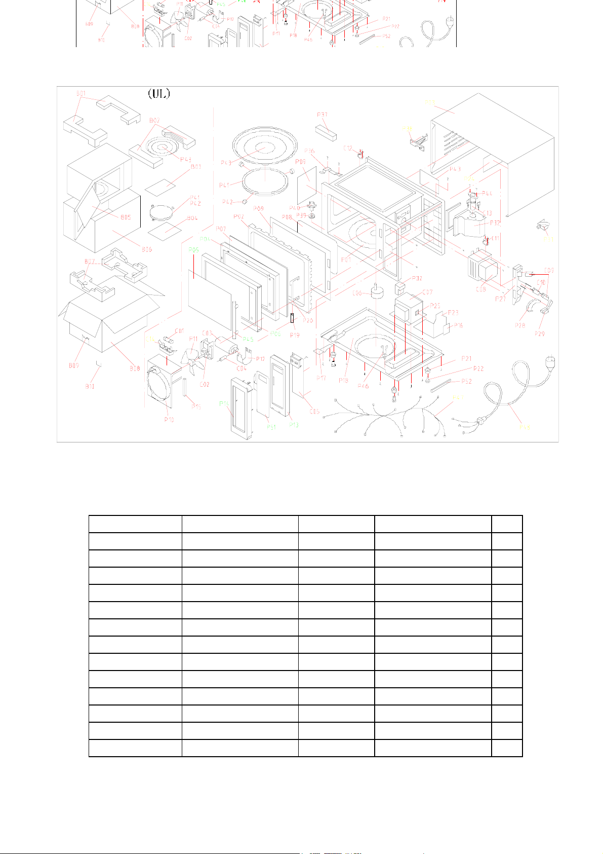
EM-Z2000S Microwave Oven Explode View
EEMM--ZZ22000000SS MMiiccrroowwaavvee OOvveenn CCoommppoonneennttss LLiisstt
COMPONENT No.
COMPONENT CODE Name Model QTY
C01 GA-1000AS23C01 Fuse 65TS 125V 20A 1
C02 GA-1000AS23C02 Fan motor SP-6309-120 1
C03 GA-1000AS23C03 H.V.Capacitor CH85 1.0µF 2200V 1
C04 GA-1000AS23C04 H.V.Diode HVM12(450mA) 1
C05 GA-1000AS23C05 PC board GAL9823 1
C06 GA-1000AS23C06 Turntable motor SM012 or GAL-5-120-TD 1
C07 GA-1000AS23C07 Transformer GAL-1000U-1 1
C08 GA-1000AS23C08 Magnetron 2M248K-N 1
C09 GA-1000AS23C09 Microswitch V-5230Qor VP533B-OFB 2
C10 GA-1000AS23C10 Microswitch V-5220Qor VP532B-OFB 1
C11 GA-1000AS23C11 Thermostat KSD180 1
C12 GA-1000AS23C12 Thermostat KSD105 1
C13 GA-1000AS23C13 Oven lamp KEI T22/120V 20W 1
3
Page 5

EEMM--ZZ22000000SS MMiiccrroowwaavvee OOvveenn PPaarrttss LLiisstt
PART PART CODE NO NAME QTY PART PART CODE NO NAME QTY
PART PART CODE NO NAME QTY PART PART CODE NO NAME QTY
P01 GA-1000AS23P01 Oven cavity 1 P32 GA-1000AS23P32 Air duct 1
P02 GA-1000AS23P02 Door frame 1 P34 GA-1000AS23P34 Wire fastener 2
P03 GA-1000AS23P03 Outer enclosure 1 P36 GA-1000AS23P36 Upper hinge 1
P04 GA-1000AS23P04 Stainless steel door 1 P37 GA-1000AS23P37 Sponge 1
P38 GA-1000AS23P38 Spacer 1
P05 GA-1000AS23P05 Door window 1 P39 GA-1000AS23P39 Washer 1
P06 GA-1000AS23P06 Door 1 P40 GA-1000AS23P40 Shaft 1
P07 GA-1000AS23P07 Choke cover 1 P41 GA-1000AS23P41 Roller ring 1
P08 GA-1000AS23P08 Inner viewing barrier 1 P42 GA-1000AS23P42 Ring wheel 3
P09 GA-1000AS23P09 Mica sheet 1 P43 GA-1000AS23P43 Glass tray 1
P10 GA-1000AS23P10 Fan shroud 1 P44 GA-1000AS23P44 Lamp holder 1
P11 GA-1000AS23P11 Fan blade 1 P45 GA-1000AS23P45 Door handle 1
P12 GA-1000AS23P12 Capacitor holder 1 P46 GA-1000AS23P46 Wire fastener 1
P13 GA-1000AS23P13 Control panel 1 P47 GA-1000AS23P47 Wire harness 1 set
P14 GA-1000AS23P14 Control panel enclosure 1 P48 GA-1000AS23P48 Power cord 1
P15 GA-1000AS23P15 Sponge 1 P51 GA-1000AS23P51 Touch key board 1
P16 GA-1000AS23P16 Nameplate 1 P52 GA-1000AS23P52 Sponge 1
P18 GA-1000AS23P18 Bottom enclosure 1 B01 GA-1000AS23B01 Foam cushion 2
P19 GA-1000AS23P19 Latch spring 1 B02 GA-1000AS23B02 Foam cushion 2
P20 GA-1000AS23P20 Door latch 1 B03 GA-1000AS23B03 Plastic bag 1
P21 GA-1000AS23P21 Foot 4 B04 GA-1000AS23B04 Owner's manual 1
P22 GA-1000AS23P22 Foot pin 4 B05 GA-1000AS23B05 Foam cushion 1
P23 GA-1000AS23P23 Transformer bracket 1 B06 GA-1000AS23B06 Plastic film 1
P24 GA-1000AS23P24 Insulating film 1 B07 GA-1000AS23B07 Foam cushion 2
P25 GA-1000AS23P25 Shock proof rubber 2 B08 GA-1000AS23B08 Packing belt 1
P26 GA-1000AS23P26 Nameplate 1 B09 GA-1000AS23B09 Carton 1
P27 GA-1000AS23P27 Microswitch mounting 1 B10 GA-1000AS23B10 Wrapping nail 12
Bracket PART PART CODE NO NAME QTY
P28 GA-1000AS23P28 Inner rotary arm 1 P32 GA-1000AS23P32 Air duct 1
P29 GA-1000AS23P29 Outer rotary arm 1 P34 GA-1000AS23P34 Wire fastener 2
P31 GA-1000AS23P31 Power cord holder 1 P36 GA-1000AS23P36 Upper hinge 1
4
Page 6

TTHHEE HHEEAATTIINNGG PPRRIINNCCIIPPLLEE OOFF MMIICCRROOWWAAVVEE
Microwave is one kind of radio wave whose wavelength is very short, frequency is very high. Therefore, it is
called ultrahigh frequency electromagnetic wave. Microwave can heat food mainly result in the mutual affect of
the food in the microwave field and the microwave field itself.
Under the affect of microwave field, the thermal effect mechanism produced from the mutual affect of the
microwave and the food includes two aspects. One is Dielectric loss of polar molecule; the other is conductive
loss of ion.
Usually, food is constituted of organism (plant and animal). The organism is formed by all kinds of polar water
molecule, polar protein molecule, and all sorts of saltion. The center of gravity of the positive and negative charge
in the molecule is not coinciding. In normal condition, the molecule is in irregular order due to its thermal action,
thus the food do not appear polarity. (FIG.1-la). Under the action of outer electric field, the positive end of the
polar molecule trend to the negative electric field, the negative end of polar molecule trend to the positive electric
field, and somewhat arrange in order through the direction of the electric field (FIG.1-1c). This phenomenon
usually is called “TORQUE POLARITY”. When the outer electric field apply for the opposite polarity, the polar
molecule then arrange an opposite direction order accordingly (FIG.1-1b). If the direction of the outer electric field
changed repeatedly, the polar molecule would repeatedly sway accordingly. During the swaying, it is
understanding that the polar molecule would produce heat due to somewhat similar friction among them. When
the electric field is applied for ultrahigh frequent microwave field from the outside, its direction would change tens
billion times per second, so do the molecule. This kind of molecule swaying producing similar frictional heat from
the interference and block of the action strength among the molecule, and changed to microscopic microwave
heating. Microwave heating not only concerned the nature of the matter itself, but also closely connected with the
electric strength and frequency. When the frequency is low, the molecule swaying rate and the acute degree of
the mutual friction among the molecule is low, and would produce much heat. When the frequency is too high, as
the swing of the polar molecule is with rotating inertia, it made the swing do not in line with the changing rhythm
of the electric field because of the friction drag, thus, actually lowed the polar molecule swaying speed. The
friction dragging degree is concerning about the magnelectric wave frequency, polar molecule shape, and the
matter’s sticky degree. To different matter’s molecule, there is different special frequency zone. Those absorbing
microwave energy from this zone are most capable to turn microwave energy to heat energy.
(a) (b) (c)
Fig.1-1
Apart from the above said action, there is another action which is electric ion under the action of microwave field,
act fiercely accompanied with the acceleration of electric field. The positive ion transfer to the negative polarity of
the field while the negative ion does opposite. Accompanying with the changing electric field, the electric ion
hanging accordingly. During the transferring, heat produced with the crash among the ion. This kind of action
takes the main effect to those microwaves heating of high salt molecule.
No matter it is the polar molecule swaying or the ion transferring, they both are turning the microwave energy
which the heating matter got from the microwave field to heat energy. From the analysis of theory, we can draw
such a conclusion that the power which a unit of volume matter absorbed from the microwave field as the
following formula:
Pa=KE fErtgδ
Pa Stands for the power the heated matter adsorbed from the microwave field.
5
Page 7
K Stands for a constant
E Stands for the microwave frequency.
f Stands for the microwave frequency.
tgδ Stands for loss angle tangent of the heated matter.
Er Stands for relative dielectric constant of the heated matter.
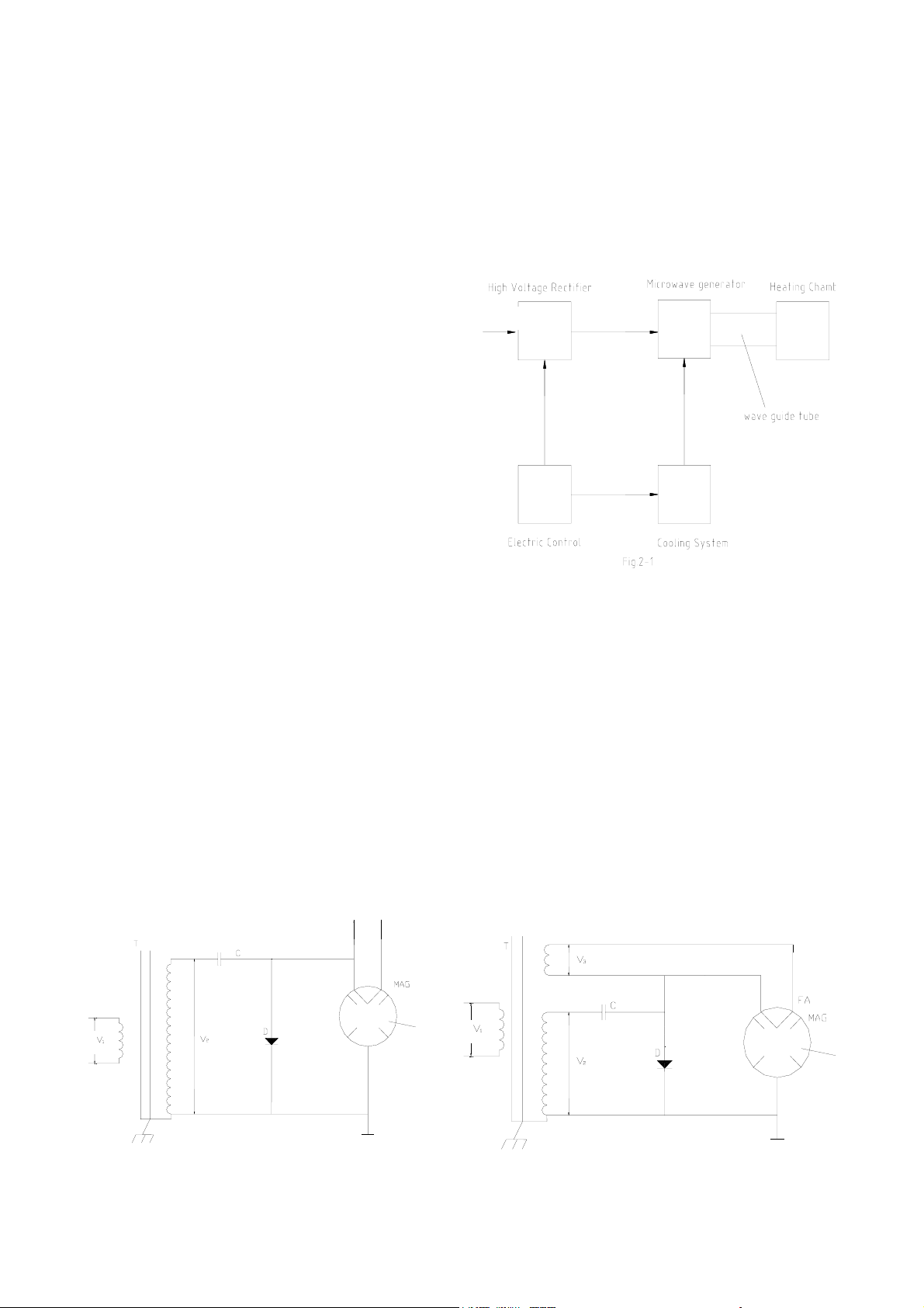
TTHHEE SSTTRRUUCCTTUURREE AANNDD WWOORRKKIINNGG PPRRIINNCCIIPPLLEE OOFF MMIICCRROOWWWWAAVVEE OOVVEENN..
Microwave oven can be classified to many kinds
according to various construction, volume and control
function. But anyhow, the main electric parts are all
composed of high voltage rectification, cooling system.
Microwave generator, electric control system and
heating chamber (FIG.2-1). Its working process are as
follows: 120V power frequency voltage transferred to
the rectifier through electric control system, and then be
changed to 4000V direct volt-age by the rectifier, and be
then transferred to the microwave generator, the
generator stars working to transfer the microwave
energy to the heating chamber for heating food through
wave guide tube. At the same time, the electric control
system set off the cooling system to cool the working
rectifier and the microwave generator to keep the oven
working steadily from a too high temperature. If
something wrong with the cooling system cause the temperature too high, the control system would cut off the
power automatically to prevent microwave generator being damaged form the high temperature. Now, we’d like to
introduce the working principle of each part of the widely used model, mechanical control and touch control
microwave oven.
11..11 HHIIGGHH VVOOLLTTAAGGEE RREECCTTIIFFYYIINNGG CCIIRRCCUUIITT..
At present, home use microwave oven adopt this high voltage rectifying circuit as shown at diagram 2-2.The
circuit is a single phase, semi-wave, double voltage rectifying circuit. The circuit has only a high voltage capacitor,
a high voltage diode, a magnetic leakage transformer besides the magnetron, is very simple.
The working principle of the circuit: 120V power boosted through the transformer, output about 2000V alternating
high voltage current when the high voltage winding is at the positive half-circle, the high voltage winding is at the
negative half-circle, the diode is cut off and the magnetron is conducted. The electricity charged at the positive
half-circle of the capacitor is series connected with the positive phase of the winding voltage, and got a doubled,
about 4000V direct high voltage, then transferred to between the cathode and the anode of the magnetron.
120V
120V
120V
Fig.2-2
6
Fig.2-3
Page 8
11..22 MMIICCRROOWWAAVVEE GGEENNEERRAATTEERR..
Microwave generator is the heart of microwave oven. The quality of a microwave oven mostly depends on the
quality of the microwave generator. A microwave generator is mainly composed of magnetron and its power
supply circuit, FIG.2-3 is the typical circuit diagram of the present used microwave oven’s generator. The power
supply circuit is composed of rectifying circuit and filament circuit.
Usually, we adopt continuous wave magnetron. It can turn the direct energy which is applied to the magnetron
after being high voltage rectified to microwave energy, the power supply circuit supply a direct high voltage
between the cathode and anode of the magnetron, a filament voltage to the cathode filament of the magnetron.
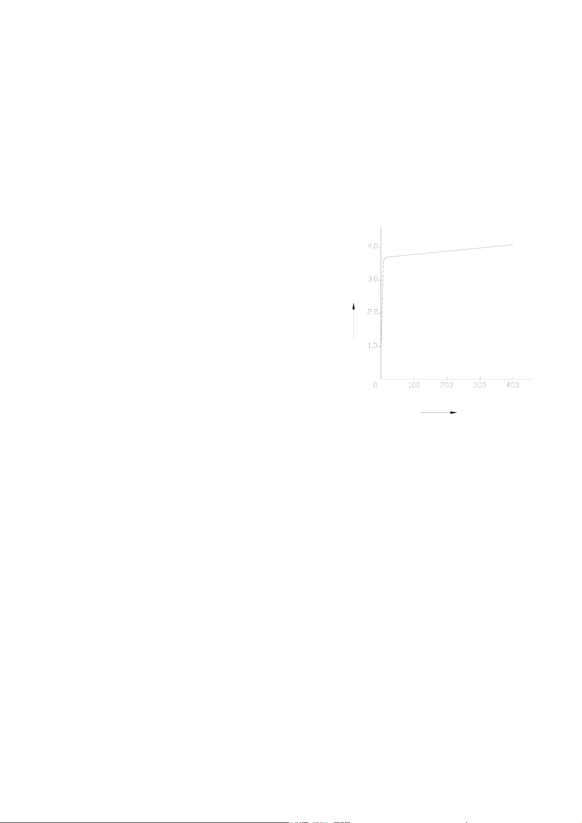
The working process of the magnetron: When the anode volt-age gradually rises from zero, the anode current is
approx.zero, the power is very small as well. When the anode voltage rises to “THRESHOLD” voltage value, the
magnetron starts oscillating, and the anode current would increase obviously, provided the anode voltage rises a
little more, the anode current would increase a lot (FIG.2-4), and would reach the rate value quickly.
If the anode voltage is undulating, it would cause the anode
current swing fiercely, even made the magnetron stop oscillating.
For keeping a steady output, the power supply circuit of the
oven must supply a stead direct current voltage. The filament
voltage of the magnetron must be supplied by an alternating
current voltage. For simplifying the circuit, it would be supplied
by the same leakage magnetic transformer with the anode
power (high voltage power). The filament of the magnetron
which the present used microwave ovens are all treated through
some special technology, and all have the cold start character.
)
V
k
(
m
b
e
e
g
a
t
l
o
v
e
d
o
n
a
But when in cold start, there still is a very strong surge electric
field attached to the surface of the anode, and would be harmful
to the anode. In order to reduce the surge voltage, the filament
of the magnetron must be connected as the FIG.2-3 shown. In
this figure, when the anode current of the magnetron circulates,
anode current
Ib(mA)
the filament current should flow to the FA end from the lower
end.
Fig.2-4
11..33 CCOOOOLLIINNGG SSYYSSTTEEMM
In the working process of the microwave oven, the magnetron often makes the anode temperature rise due to
anode loss
caused by the electronics strike the oven surface and the heat radiate of the cathode. To prevent the anode
temperature rise too high, thus affect the working steady and its life span, it is necessary to cool the magnetron.
According to the different models and rate output of the magnetron, compelling wind cooling and flowing
water-cooling can be adopted. Usually, the home used microwave oven adopts the compelling wind cooling
method, and all are fixed with cooling fin.
Cooling system includes fan motor, air duct, air entrance, air vent etc. The flowing direction of the cooling wind
should. Be parallel to the cooling fin of the magnetron. Generally, we adopt the method of air blast rather than air
absorb. And all the cabinet of the oven is with air entrance and air vent, the hot wind blowing through the
magnetron is guided with air tube to improve the cooling effect. In the technical parameter chart of the magnetron,
it usually will give out the requirement of cooling wind. A shortage of cooling wind would damage the character of
the magnetron, even burn out the magnetron. The amount that the fan blasted should not be less than the
requirement. When fix the fan, attention must be paid to prevent the cool wind from blowing directly to the glass
part of the magnetron to avoid blasting.
11..44 EELLEECCTTRRIICC CCOONNTTRROOLL SSYYSSTTEEMM..
To those mechanical control microwave oven, electric control system mainly composes of interlock switch, timer,
power distributor and thermal cutout, etc. The electric control system of those tough control microwave oven is
mainly composed of interlock switch, computer controller and thermal cutout, etc.
7
Page 9

11..44..11 DDOOOORR IINNTTEERRLLOOCCKK SSWWIITTCCHH
Drawing 2-5(a) is the circuit and construction diagram
of the door interlock switch of a microwave oven. It
mainly consists of interlock switches (S1, S2), and
monitor switch (S3), door hook and starting mechanism
of the door interlock switch.
There fixed hooks on the oven door, and opened two
rectangle hole at the corresponding place at the right of
the oven and the hook. Inside each rectangle hole,
L
E
N
there fixed a micro switch. When the oven door closed,
the two hook on it would insert into the rectangle hole,
and just push down several micro switches. At that time,
S1, S2 are closed, S3 is cut off, and the microwave
oven is under preparation of working.
door closed
To that mechanical control microwave oven, no sooner
you turn the time switch to set the heating time than the
power would be supplied to the back to start the oven. To those touch
control microwave oven, hardly do you set the heating time and power,
and touch the start button when the power would supplied to the back to
start the oven.
When pressing down the door release button or pulling the door handle
to open the door, the safety interlock switches S1, S2 are cut off, and
the monitor switch S3 is closed, and the microwave oven would stop
operating immediately. Provided due to some man - made or the
appliance itself reasons, when the door is open, and the safety interlock
switches S1, S2 are not automatically cut off, due to the existence of the
fuse
ch holder
tch
itch
main latch switch
pilot switch
(a)
Fig.2-5
door hook
S
1
3
S
2
S
assistant latch switch
latch switch holder
latch switch
pilot switch
monitor switch (S3) which is still at conducted condition, the monitor
switch would immediately make the 120V voltage short-circuited and
screw
blow up the fuse, and will never let the microwave oven working when
the door is open.
From this we can understand the function of the interlock switch is
when the door is unclosed, the oven wouldn’t work, when the door is
opened when the oven is working, it would stop the working
door hook
latch switch
pilot switch
immediately (FIG.2-5b).
11..44..22 TTIIMMEE AANNDD PPOOWWEERR DDIISSTTRRIIBBUUTTOORR
door release button
Fig.2-5(b)
screw
Time and power distributor is mainly composed of timer motor and two
sets of gear switch S4 and S5. When the timer is at zero position, the gear switches are cut off, when the heating
time is settled, the gear switch is closed. When started
the oven, the time motor starts working. When it
reaches the settled time, it would cut off the gear
switch (s4) to step the oven working. The gear switch
timer & power motor
transformer
(S5) is designed for controlling the output of the
microwave oven, actually for controlling the output of
the magnetron. It mainly by the method which make
120V
the magnetron working internally at the same working
point to change the output of the magnetron. This
4
S
5
S
method was called “CONDUCTION RATIO CONTROL”.
But there is another method which is called
Fig.2-6
“ELECTRIC LEVEL CONTROL” which is through
changing the working point (such as anode voltage or magnetic field) to change the output of the magnetron.
Because of conduction ratio control method is low cost, high function and high reliability, it is widely used for
8
Page 10

those microwave oven which have the power control function.
FIG.3-1 is the power control circuit diagram of brand microwave oven, WP700. This is a typical instance of
conduction ratio control. This oven adopt time and power controller as a whole. When a 120V, 60Hz alternating
current is inputted, the time and power motor is always at working condition. At the FIG.2-7, S5 is always
conducted. Made the S5 working 30 seconds as a circle, the conduct time can be successively adjusted from 5
seconds to 30 seconds. When power select switch is set at “HIGH”, S5 is always conducted, the output of the
microwave oven is 700W(full power) when the power select switch is set at defrost position, S5 would conduct for
14.4 seconds, and cut off for 15.5 seconds, and the average output of the oven is 336W.
11..44..33 TTHHEERRMMAALL CCUUTTOOUUTT
Thermal cutout actually is a thermal sensor switch, usually, it is fixed on the shell of the magnetron, and series
connected with the primary circuit of the magnetron to control the power input. At normal condition, the thermal
cutout is always conducted (FIG.2-8). When something wrong with the cooling system that cause some abnormal
conditions, such as molding or thermal breakdown, which made the temperature of the magnetron reach the limit
value. Then, the thermal cutout would work to turn off the power to prevent the magnetron from being damaged.
11..44..44 HHEEAATTIINNGG CCHHAAMMBBEERR
Heating chamber is the place where the microwave and the food affect mutually. There are lots kinds of chamber.
Accord-ing to the working characters, it can be classified to carton type, cavity type, radiation type, slow type
(surface wave type), etc. The present adopt chamber for food cooking microwave oven is the typical carton type
heating. (FIG.2-8). The heating chamber is mainly composed of oven door and oven cavity. From the microwave
theory, it is a microwave resonant cavity that can contain many kinds of oscillating models simultaneously.
Microwave enters into the oven cavity through the wave guide and the coupling appliance, and most of its energy
is absorbed by the food after it is reflected in the cavity repeatedly, those which haven’t been absorbed will be
reflect to the magnetron. A good designed oven cavity should have a good impedance matching with the
magnetron, the energy should be less reflect, and distribute evenly in the oven cavity, improve the heating
efficiency. Generally, at the same input power, the larger the cavity, the less the energy density a unit volume
would have in the oven, and the more energy on the inside wall of the cavity would lose, thence, it would certainly
slow down the heating speed, low the heating efficiency. Moreover, too big of the cavity would either waste the
material or appears very heavy. The material for cavity usually use non - magnetic stainless steel or zinc - plating
steel, and have no high requirements for the conducting rate. The inside coating of the cavity requires beautiful in
look, durable when use (should be resistant against damp, heat, acid and alkali), it should also comply with the
food health requirements.
To improve the heating evenness there often fixed a turntable glass tray at the bottom of the cavity (FIG. 2-8). It is
through changing the relative place of the microwave and the heating matter to improve the heating evenness.
The turntable tray is usually made of heat – resistant glass, the glass contains some dielectric loss, it can,
somewhat, protect the magnetron when the cavity loading less.
There often fixed a dust – proof, low – loss and heat – resistant dielectric cover (such as mica sheet). Sometimes,
an impedance matching metal stick was fixed near the coupling or in the wave guide.
The door is designed for inspecting, taking and placing the heating food, it is also one side of the cavity (FIG .2 -
1. Safety interlock switch
2. Door window
3. Air vent
4. Roller Shaft
5. Turntable supporter
6. Glass tray
7. control panel
9
Page 11

8). It is the most liable place where microwave leakage occurs. Especially, after a long time using, the microwave
leakage would enlarge at the hinge and the hook. Anyway, mechanic damage would also cause large amount of
microwave leakage. Therefore, the main methods designed for preventing microwave leakage of the door are as
follows:
1) Assemble a layer of steel filament or a thin metal plate with many holes at the middle of the window to made it
is possible to observe the heating as well as shielding the microwave.
2) The widely used seal measurement at present
is to assemble a current – resistant construct
between the door and the doorframe. FIG.2-9 is
the typical construction fig of the door. It was
current-resistant
constructure
designed according to the theory of
“THETRANSFERING LINE ONE–FOURTHWAVE
LENGTH IMPEDANCE CHANGER”. Although
there is no connecting point from a mechanical
point. It is sealed at the seam from the point of
front door plate
noise filter
electricity, so it is called “CURRENT-RESISTANT”.
Recently, with the installation of noise filter in the
current resistant trough, the effect to restrain the
microwave leakage (include high subharmonic)
Fig.2-9
oven door
have been much improved.
TTYYPPIICCAALL CCIIRRCCUUIITT AANNAALLYYAASSIISS OOFF MMIICCRROOWWAAVVEE OOVVEENN
We have introduced the structure and the working principle of the microwave oven previously. We shall analyze
the complete set circuit of the microwave oven link with the practical circuit at this chapter.
SCHEMATIC DIAGRAM
NOTE: Door is closed
Unit is not operated
MAGNETRON
FA
(MAG.)
FUSE
THERMAL
CUTOUT
MONITOR
SWITCH
(OVEN)
120V
60Hz
L
N
PRIMARY
SWITCH
FAN
OVEN
MOTOR
LAMP
FM
L
MAIN
RELAY
MT
TURNTABLE
MOTOR
POWER
RELAY
C
F
HIGH
VOLTAGE
CAPACITOR
HIGH
VOLTAGE
DIODE
SECONDARY
SWITCH
HIGH
VOLTAGE
TRANSFORMER
LOW VOLTAGE
TRANSFORMER
DIGITAL PROGRAMMER CIRCUIT
10
Page 12

Fig.3–1 is the practical circuit diagram of a microwave oven. Its corresponding working conditions are as follows:
The door closed, SW1 and SW2 turned on, SW3 closed, power control relay has no power, R1, R2 is cut off.
When cooking, touch the starting switch to power the timer and the power relay. RY1, RY2 closed the power
supply to the anode of the magnetron and the filament, changing the power frequency electric energy to
microwave energy, the microwave energy then transferred to the heating chamber for food heating. At the same
time, the lamp turned on, the fan motor begins to cool the magnetron. The turntable motor set off to drive the food
around and making the food heated evenly. The microcomputer begins reckon the time, when it reached the sets
time, power relay are cut off, the power of the lamp, all the motor and the magnetron are cut off, the food –
heating process ended. During the heating, if the door was opened, the interlock S1, S2 will cut off, S3 will close,
all the motors and the magnetron will also be cut off, the lamp will turn on, the oven stop heating immediately. If
heating need go on, just push down the starting button and closed the door, the oven will continue its working.
When something wrong with the fan motor or the air vent was blocked that breakdown the cooling system, the
magnetron temperature would rise high very quickly. When the temperature reached the working point of the
thermal cutout (S6), S6 will be cut off immediately to cut off the power supply to the magnetron and the
magnetron will stops working right away. The PC board is cut off to prevent the magnetron from being damaged
by overheating. When the thermal cutout is cut off, the magnetron, motors and the lamp would stop working
simultaneously. Moreover, the thermal cutout has the self - resuming character, when the temperature lowered, it
will resume to close condition.
Circuit diagram of computer controlled microwave ovens:
Circuit diagram for mechanical controlled microwave ovens:
HHOOWW TTOO AASSSSEEMMBBLLEE AANNDD DDIISSAASSSSEEMMBBLLEE MMIICCRROOWWAAVVEE OOVVEENN CCOOMMPPOONNEENNTTSS
In the following pages, we will introduce the ways in which the various parts of a typical microwave oven can be
disassembled and assembled.
11..55 TTHHEE CCAABBIINNEETT
To disassemble the cabinet
1. Pull out the power plug.
2. Loosen the four screws at the back of the oven with a “+”- screwdriver. (FIG.4-1a)
3. Push the cabinet back 25mm according to the arrow direction shown at FIG.4-1 (b), and the cabinet can be
taken off.
To assemble the cabinet
1. Put the cabinet on the oven, and push it full ahead.
2. Check whether the up, right and left troughs have been inserted with the curved with the curved rim of the
oven (FIG.4-1 (b)). If the cabinet and the oven are not tallied exactly, then it should be reassembled or those
untallied parts should be smoothed.
3. Tighten those four screws, please make sure that one of the screws should have a plum blossom shape
washer to keep a good earth.
11
Page 13

11..66 TTHHEE DDOOOORR CCOOMMBBIINNAATTIIOONN
six-angle screw
To disassemble,
1. Pull out the power plug.
2. Take off the cabinet.
3. Loosen the two six –angle screws of left hinge (up)
hinge(up)
with a socket wrench (FIG.4 - 2).
4. Push the door release button to have the hook out
oven
(FIG.4 -3).
5. Pull the hinge with the door out of the oven
together, and take off the washer of the hinge (low)
shaft (FIG.4 - 2).
6. Pick up the ten inverse hooks which around the
cover with a small screwdriver
carefully(ATTENTION: the cover is made of
Fig.4-2
plastics, and is very liable to be broken), and take
out the cover.
7. Take off the two screws at the door side
with a “+”-screwdriver
8. Take off the hinge (up)(FIG.4- 2).
9. Apart the doorframe from the doorplate
(FIG.4-2).
10. Take off the hook spring with a pointed
plier, then the hook combination.
11. Clamp the window plate with hand, push it
door hook
latch switch holder
latch switch
door hook
pilot switch
latch switch holder
latch switch
pilot switch
down according to the arrow direction,
and take it off.
(a)
(b)
To assemble the door combination(see sketch
4-2 to 4-5)
1. Apply proper silicon grease or lubricating
Fig.4-3
grease on the “★” mark of the hook first, then fix the hook on the oven door, and the spring on its place
(FIG.4 - 5), check whether the hook is operating in normal.
2. Apply proper silicon grease or lubricating grease on the “★” mark of the hinge (UP), install the hinge (UP) in
the hole at right above of the door as FIG.4 - 2, then install the window on the door as FIG.4 - 1, make sure
the hook won’t out. Then tighten each hook on the window to the trough of the door. After assembled, check
whether the door hook is working in normal.
3. Tear off the back protective paper of the window, then the sides of adhesive tape as FIG.4 – 1, and stick it on
the window, Tear three right sides protective paper about 10mm, and fix the window in the doorframe as
12
Page 14

FIG.4 – 1.
4. Tear off the adhesive protective paper of the lining and stick it on the door as FIG.4 – 1, slip the hook on the
doorframe, and fix the doorframe on the door, tighten it with “+” – screws. After assembled, check whether
the hook working in normal and whether the hinge (UP) is its position.
5. According to the FIG. 4 –4 shown, paste the inner lining inside the doorframe, make sure it is pasted
smoothly, and should have no air bubble.
6. Slip the washer in the hinge shaft, then put the hinge shaft in the hinge hole on the bottom of the oven, the
hinge in the rectangle hole on the left above, and hooked it with the door hook.
7. Place a 0.15mm thin paper between the door and the oven, level the door and the oven, then push the door
close to the oven, and tighten the two screws of the hinge (UP) and paint them.
11..77 TTHHEE CCOONNTTRROOLL PPAANNEELL AANNDD TTHHEE DDOOOORR RREELLEEAASSEE MMEECCHHAANNIISSMM..
1. Pull out the power plug.
2. Take off the cabinet.
3. Discharge between one end of the capacitor and the baseboard with a
screwdriver.
To disassemble
1. Pull out the terminal plug of the time and power distributor.
2. Take off the screw which fix the control panel with a “+” – screwdriver
(FIG.4 - 6)
3. Take off the control panel.
To assemble,
(1) Place the two buckles under the control panel into the two rectangle
holes under the oven as FIG.4 – 6, then make close of the control panel and
the oven with being fixed with a screw. Plug in the terminal plug.
11..88 TTHHEE MMAAGGNNEETTRROONN..
Firstly, do as 1,2,3, steps at Ⅲ of this part.
To disassemble,
1. Take off the screw beside the oven lamp (FIG.4 - 8).
2. Take out the four screws which fixed the magnetron, and take the magnetron off (FIG.4 - 7).
screwe
magnetron
lamp shade
Fig.4-7
magnetron
screwe
magnetron holder
thermal cutout
magnetron holder
Fig.4-8
To assemble the magnetron,
1. Check whether the copper filament weaved washer of the magnetron antenna has been placed well. It
should not be fixed if there is no copper filament weaved washer, for it may cause the magnetron and the
oven can’t earth well, and cause large amount of microwave leakage. Attention : When a new oven matches
a magnetron, the meatl lustre at “★” mark should be polished with a sand paper (FIG.4 -7).
2. Aim the head of the magnetron antenna to the hole of the wave guide housing, tighten the four screws of the
13
Page 15

magnetron vertically, and also tighten the screws of the lampshade (FIG.4 - 8).
3. Plug in the two terminals of the magnetron filament and the thermal cutout.
11..99 TTHHEE TTRRAANNSSFFOORRMMEERR..
Firstly, do as the 1,2,3, steps at Ⅲ of this part.
Dismantling steps for the transformer: (as FIG.4 -9).
1. Pull out all the terminal of the transformer.
2. Turn the microwave over.
3. Take off the right baseboard with the transformer after loosened the four screws, which fix the board on the
oven. (4-10).
4. Take off the four screws, a, b, c, d with a “+”- screwdriver.
5. Take off the right baseboard, the seat and the rubber space between the transformer and the oven.
screw
base board
transformer
seat
Fig.4-10
Fig.4-9
to mount the transformer,
1. Place the transformer as the FIG.4 - 9, tear off the protective paper of the rubber lining tape, stick it on the
transformer as shown on the figure. Then put on the seat and the right base board, make sure the screw
hole are tallied, then tighten the four screws for the high voltage winding is earthing here.
2. Fix the transformer on the oven as FIG.4-10.tear off the protect paper of the rubber spacer, set it between the
transformer and the oven, make sure the adhesive side is sticked on the oven.
3. Plug in all the terminals of the transformer precisely.
11..1100 TTHHEE FFAANN MMOOTTOORR..
Firstly, do as the 1, 2, 3, steps of Ⅲ of this part.
To disassemble,
1. Pull out the two terminal of the fan motor (FIG. 4 –11).
2. According to the FIG.4 –12, pull out the lead plug which
marked “A” and “C” from the thermal cutout and the fuse
housing separately, and take off the earthing screw which
marked “B” (FIG.4 -12).
3. Take out the power supply cord from the trough as the
figure shows.
4. Loosen the screws shown on the FIG.4 –13 with a “+” –
screwdriver, and take off the fan holder.
5. Take off the fan from the fan motor shaft as FIG.4 –14, then the fan motor.
to mount the fan motor,
lead
fan motor
Fig.4-11
power supply cord
14
Page 16

1. Assemble the fan motor as FIG.4 – 14. Drip the glue on
the “★” place of the fan motor shaft, and fix the fan on the
motor, make sure it must be fixed to the bottom of the
shaft. Attention: The fan motor shaft should not be curved,
the fan should have no abnormal stick up. After assembled,
check whether the running fan would knock the fan holder.
2. Assemble the fan holder as FIG.4 – 13, Then connect the
power supply cord with the two wires of the fan motor, and
tighten the screws as FIG.4 – 11 and FIG.4 – 12.
earthing screw
fuse housing
power supply cord
Fig.4-12
fan
Fig.4-13
11..1111 TTHHEE CCAAPPAACCIITTOORR..
Firstly, do as the 1, 2, 3, steps of Ⅲ of this part.
To disassemble,
1. Pull the wires of the capacitor out (4-15).
2. Loosen and take out the screw which fix the capacitor clip
with a “+” – screwdriver, and take out the clip and the
capacitor. (4-15).
To assemble,
1. Place the capacitor in the capacitor clip with the end which
have three foot near the diode (4-16).
2. Insert one end of the clip in the fan holder trough (FIG.4-15).
3. Tighten the screw, which fix the capacitor clip.
4. Plug in all the plugs of the capacitor.
fan motor
Fig.4-14
capacitor
diode
back board
screw
fan holder
screw
Fig.4-15
11..1122 TTHHEE DDIIOODDEE..
Firstly, do as the 1, 2, 3, steps of Ⅲ of this part.
To disassemble,
1. Pull out the diode plug, which plugged in the
capacitor.
2. Loosen the screw, which fixed the diode, and
take the diode off.
To assemble,
transformer
15
magnetron
H.V.fuse
Fig.4-16
capacitor
diode
Page 17

1. Insert one end of the diode to one feet of the capacitor’s connect piece.
2. Fix the diode with one screw (pay attention to the polarity of the diode, refer to FIG.4 - 16).
11..1133 TTHHEE TTUURRNNTTAABBLLEE CCOOMMBBIINNAATTIIOOMM..
Firstly, do as the 1, 2, 3, stops of Ⅲ of this part.
To disassemble,
1. Turn the microwave oven over (FIG. 4- 17).
2. Take off the two screws which fix the middle base board with a
“+” – screwdriver and take off the middle cover (FIG.4 - 18).
3. Loosen out the two screws of turntable motor with a “+”-
screwdriver, take out the turntable motor and pull out the two
wires (4 -17).
Assembling steps:
1. Put the motor shaft into its connecting hole, and fix the motor
with two screws (FIG.4 - 17).
2. Plug in the two wires.
3. Assemble and fix the middle base board with two screws
(FIG.4 - 18).
4. Turn the oven back.
5. As the FIG.4 – 19 shown, fix in the turntable shaft supporter,
the place in the roller ring and the glass tray as FIG .4 – 20.
turntable shaft supporter
roller ring
Fig.4-19
Fig.4-17
Fig.4-18
11..1144 TTHHEE DDOOOORR SSAAFFTTYY IINNTTEERRLLOOCCKKSS..
Firstly, do as the same with 1, 2, 3, steps of Ⅲ of this part.
Steps for dismantling:
(1) Pull out the terminal plugs of the interlock switch and the pilot switch.
(2) Loosen out the two screws which fixed the switch holder with a “+”- screwdriver, and take the switch holder
off.
(3) Take off the interlock switch and the pilot switch from the holder.
(4) Take off the switch connecting lever arm and the working lever from the holder.
Assembling steps:
(1) Slip on the connecting lever arm and the working lever into the switch holder.
(2) Assemble the interlock switch and pilot switch to the switch holder, make sure they are assembled correctly.
(3) Tightly fix the holder with two screws.
(4) Check the position of the hook and the switch holder. Close the door, push and pull the low and up part of the
16
Page 18

front door pla
latch switch hold
door to check whether the door is flexible. If it does, back
and front position of the holder should be adjusted.
Provided the up hook is loose, the door should be pushed
more closely to the oven, and pull the holder inside closely
after loosen the screw which fix the holder, then, tighten the
screw and check whether it is still loose. If it is not or the
loose is minor, it would be OK. Open the door, then close it
lightly, check whether the hook is in position, if not,
readjustment is needed. If the loose is at lower part of the
door, the adjust methods is the same with the above said
steps but the screw is the one below (FIG.4 - 21).
screw
Fig.4-21
11..1155 TTHHEE CCOONNTTRROOLL PPAANNEELL OOFF AA TTYYPPIICCAALL
MMIICCRROOWWAAVVEE OOVVEENN
Pull out the power plug.
Take off the cabinet.
Discharge between one end of the capacitor and the
control panel
light tough switch
PC board
baseboard with a screwdriver.
Means of dismantling the PC board and door release
mechanism:
(1) Pull out all the terminal plug of the PC board.
(2) Loosen out the two screws which fix the control panel
with a “+”- screwdriver (FIG.4 -6).
(3) Take off the control panel.
(4) Take off the three “+”- screws which fix the PC board
Fig.4-22
as the FIG.4 – 22.
(5) Take off the range terminal plugs as FIG.4 – 24 shown, that is press the two places according to the arrow
direction at the figure, while pull it up about 2mm, then off
the row plastic board.
(6) Take off the PC frame.
light tough switch
(7) Tear off the undried glue of the light touch switch (FIG.4
- 23).
control panel
to assemble the PC board and door release mechanism,
(1) Tear off the undried glue patch of the light tough switch
(1) and (2) as the Fig.shown, and place them into the
rectangle hole of the surface of the plastic board.
(2) After uprighted the light tough switch, tear off the
protective paper on the back, and stick it on the plastic
board smoothly.
Fig.4-23
(3) Tear off the protective paper of the light touch switch (2), and stick the switch on the back of the plastic board
smoothly.
(4) Assemble in the PC frame and PC board as FIG .4 –22,
and fix them with three “+”- screwes.
(5) Fix the range wires as FIG.4-24, the means are: Insert
the range wires first, make sure that its notch is tallied with
the flange of the row seat, then, press it down to its normal
position.
(6) Fix the control panel on the oven (FIG.4-6).
(7) Plug in the terminal plugs of the PC board.
17
Page 19

BBRREEAAKKDDOOWWNN AANNAALLYYSSIISS AANNDD TTHHEE MMEEAANNSS OOFF OOVVEERRHHAAUULLIINNGG
Before overhauling a microwave oven, you should judge the breakdown and the cause correctly, then you can
repair it with corresponding ways. The overhauling must be proceed in order, any hasty conclusion is not
recommendable, otherwise over-working would be done when repair. The microwave oven may occur compound
breakdown due to all kinds of different reasons, thus, when overhaul, they all should be taken into consideration.
Special attention must be given to the microwave leakage and the electric insulation when examine because they
may do harmful to the repairing staff.
11..1166 EEXXAAMMIINNIINNGG TTHHEE BBRREEAAKKDDOOWWNN CCAAUUSSEESS..
How to examine a microwave oven with breakdown? A better means which demonstrated in practical operating
are through inspecting and listening. On the basis of large amounts of perceptual knowledge, you can judge and
analysie the break down quickly and correctly.
11..1166..11 IINNSSPPEECCTTIIOONN..
Inspect whether the oven shape is disordered and where is the disordered position, If any. It is normal if the
cabinet disordered a little, but abnormal if the oven, the door disordered, the door hook broken, the door crooked,
or there are too much looseness between the door and the oven after the door is closed .
11..1166..22 LLIISSTTEENNIINNGG..
Listening to the sound of the oven operating and the noise of the fan. Minor “wen wen” noise, cycling“kala”noise
and “shishi” noise should be considered as normal. But it is abnormal if the following noises occur:
(1) Sound “wen wen ” noise.
(2) Long time “shishi” noise.
(3) Strike sound like “Pipa pipa”
11..1177 SSPPOOTT EEXXAAMMIINNIINNGG SSTTEEPPSS OOFF TTHHEE MMIICCRROOWWAAVVEE OOVVEENN
11..1177..11 EEXXAAMMIINNEE TTHHEE MMIICCRROOWWAAVVEE IINNSSUULLAATTIINNGG RREESSIISSTTAANNCCEE
Measure the insulating resistance with a avometer or a
megaohmmeter the value should not be less than 2 megaohms.
Otherwise, part examination should be taken at once. Such as
checking whether the motor, the thermal cutout, the transformer or
the capacitor are electricity leaking.
glass tray
11..1177..22 EEXXAAMMIINNAATTIIOONN OOFF TTHHEE RREESSIISSTTAANNCCEE VVAALLUUEE OOFF TTHHEE
MMIICCRROOWWAAVVEE OOVVEENN..
Close the door, set the time (the oven is at operating condition but
the power plug haven’t been plugged in ), measure the two feet (L N) of the power plug with R×1 grade of an avometer, the resistance
value should be about 2.5 ohm. If open circuit occurs, then you must
check whether the 8A fuse is broken、the primary winding of the transformer is open circuit、the thermal cutout is
open circuit or not, you must check whether the interlock device is put through or all the plugs are connected well.
If short circuit occurred or the resistance less than 1.5 ohms, you
should check whether the primary winding of the power transformer
is short – circuited or part short – circuited.
11..1177..33 EEXXAAMMIINNAATTIIOONN OOFF MMIICCRROOWWAAVVEE LLEEAAKKAAGGEE..
Measure the microwave leakage with a microwave leakage measure.
Place a graduate of 275ml water at the middle of the glass tray of the
oven (FIG.5 - 1). Close the door, power set high, time set to 3
minutes, press the starting button to operate the oven. After rectified
the microwave leakage measure, measure around the door crack,
those hole position of the window and the air vent at four sides of the
oven with the probe of the measure. When measure, the moving
18
Fig.5-1
Page 20

speed of the probe should not exceed 25mm per second, and
the measuring direction should be the same with the outing
direction of the probe should not exceed 25mm per second, and
the measuring direction should be the same with the outing
direction of the microwave leakage (FIG.5 - 2)..
When measuring the ultimate value of microwave leakage of all
the measure position should not exceed 1 milliwatt/cm2, of
should be considered as abnormal.
11..1177..44 EEXXAAMMIINNEE WWHHEENN TTHHEE OOVVEENN AATT OOPPEERRAATTIINNGG,, BBUUTT TTHHEE
FFOOOODD CCAANN’’TT BBEE HHEEAATTEEDD..
(1) Examine when the lamp is on, the glass tray is cycling, the
fan operating in normal:
Take off the cabinet, starting the oven, measure the plug of the
transformer with an avometer to see whether it is enough to
120V. If it is enough to 120V, then the secondary high voltage of
the transformer should be examined as FIG.5 – 3.
Measure it with the 2500V-alternating grade of model 500
avometer. One rod of the avometer connects the iron core of the
transformer, the other rod connects the secondary high voltage
plug (FIG.5 - 4). The avometer reading should be about 2100V
(when measure, be careful with the high voltage). If no voltage
at all, it indicates that the transformer has broken, and should be
replaced by a new one. If it is enough to 2100V, then check the
filament voltage of the transformer with alternating 10V grade of
an avometer, the value should be about 3.4V (FIG.5 - 5).
If there is no voltage at all, it indicates the transformer has
broken, and should be replaced by a new one. If it is enough to
3.4V, check the filament resistance of the magnetron, measure
the filament plug with the R×1 grade of a avometer (FIG.5 - 6). If
it is open – circuited, it indicates the magnetron has broken, and
should be replaced by a new one. It is normal if the resistance
very small. Then check whether the magnetron steel has broken,
if broken, replace with a new magnetron.
If there is no problem with the magnetron, check the high
voltage diode then. Measure the diode with R×10K grade of an
avometer, the “+” rod end of the avometer connect the cathode
of the diode, the “-” rod end of the avometer connect the anode
of the diode (FIG.5 - 7).
The avometer reading should be about 150 thousand ohms.
The change the rod to different electrode, the reading should be
“∞” . If the reading is very small, and near to short circuit, it
indicates the high voltage diode has been punctured, and
should be replaced by a new one.
If the high voltage diode is OK, then check the forwarding plug
Fig.5-3
Fig.5-4
Fig.5-5
magnetron
of the transformer to see whether it is enough to 120V. If it is not
enough, check the micro – switch of the time and power
distributor. Connect the two rods of the avometer to the 1,2 place
of the timer with R×1K grade. It is normal if the reading is “0”
when at cut off condition. If the reading is “∞”, it indicates the
micro switch has broken, and the timer should be replaced by a
new one. If all the above examination shows normal ,then check
whether the terminal plug of the magnetron and the capacitor
have loosened, if it is loosened, pinch it tightly with a pliers.
19
Page 21

11..1177..55 EEXXAAMMIINNEE TTHHEE SSTTAARRTTIINNGG AANNDD TTHHEE 88AA FFUUSSEE OOFF TTHHEE
MMIICCRROOWWAAVVEE OOVVEENN..
Pull out the power plug, take off the cabinet, discharge the
capacitor, measure the resistance value of the primary
winding and the secondary winding of the transformer with an
avometer (FIG.5 – 10 and FIG.5 - 9). The resistance value of
the primary winding should be about 2.2 ohms, the secondary
winding should be about 130 ohms. Otherwise, it indicates the
transformer has broken, and should be replaced by a new
one.
If the transformer is normal, then the high voltage capacitor
should be checked. Pull out the connecting plug of the
capacitor, and measure it with R×1 grade of an avometer, the
two rods of the avometer connect the two polarity of the
capacitor. When they just connected, the reading of the
avometer should be zero, then increases to nine megaohm
slowly. Change the rod to different polarity, the reading repeat
from zero to nine megaohm (FIG.5 - 11), it means the
capacitor is normal. If the indicator of the avometer can’t point
out from zero to nine megaohms, it indicates the high voltage
capacitor has broken, and should be replaced by a new one.
If it is normal between the two pole of the capacitor, then the
insulation between the capacitor pole and the cabinet should
be measured with R×10K grade of an avometer. The
resistance value should be “∞” (FIG.5 - 12). If it is short
circuited or have a number reading, it indicates that the
capacitor has been punctured or electricity leaked, and should
be replaced by a same model, same capacity one.
Fig.5-8
Fig.5-9
Fig.5-10
If the resistance value of the capacitor’s two pole are “∞”, the capacitor is normal. Then check the earth of the
magnetron’s two filaments to see whether they are short –
circuited (FIG.5 - 13). If they are short – circuited and the
filament strikes the shell of the magnetron, it indicates the
magnetron has broken, and should be replaced by a new,
same model one.
If the magnetron is also normal, then test the pilot switch.
Pull out the two plugs of the switch. Measure it with the R×1
grade of avometer, the two rod connect the plug of the
switch, the resistance value should be “∞” (FIG.5 - 8).
Then press down the pilot switch with a screwdriver, if the
reading of the avometer pointed to zero, it indicates the pilot
switch has broken, and should replace it with a new, same
model one.
Fig.5-11
20
Fig.5-12
magnetron
Page 22

21
door pushing
part at
screw
right above
micro switch
door pushing
screw
part at
right below
11..1188 RREEPPAAIIRRIINNGG MMEETTHHOODD OOFF SSEEVVEERRAALL BBRREEAAKKDDOOWWNN
1. Repair when there occurred large amounts microwave
leakage. There are many factors which may cause microwave
leaking. Following mentioned may be the main causes of
microwave leakage:
(1) The door deformed, the hinge loosed or damaged that
caused the door can not close tightly.
(2) The door pressing cover or the embed piece damaged or
come off.
(3) Obvious damage or uneven of the oven.
(4) There are filth between the door and the oven.
(5) The door and the oven are serious loosed after the door
closed.
(6) The crack of the door shielding net cover.
Before repairing, check whether the above listed point are
existed, if not, can you start the microwave oven. Place a graduate of about 275ml water at the middle of the
glass tray, close the door, time set at 3 minutes, power at high, make the oven operating in normal. Rectify the
microwave leakage measure, measure the amount of the microwave leakage around the oven with its probe. If
there are places which the leakage exceeds the standard requirement, then repair them accordingly. If the
leakage amount exceeds 1 milliwatt/cm2 at the left door crack,
then pull out the power plug, take down the cabinet, adjust the
screws of the hinge (up and low) as figure5-14 to less the gap
between the door and the oven. Then measure again, the
leakage amount should be less than 1 milliwatt/cm2. Generally,
it should be controlled below 0.75 milliwatt/cm2 with some
allowance.
If the leakage occurred at the right door crack, adjust the
screws which fix the interlock holder and the hook. If the
leakage is the larger side at the right – above of the oven, then
adjust the upper screw as FIG.5 – 15. Loosen out the screw,
push the door close to the oven to hook the door hook with the
plastic parts, then tighten the Screw again. If the leakage is
larger at the right – below, then adjust the lower screw as FIG. 5
– 15. Loosen the screw, push the door close to the oven to hook the door hook with the switch holder tightly, then
tighten the screw again, and open and close the door repeatedly, to check whether the door can operate flexibly,
whether the hook and the switch are in their normal position. If it is not in position, then adjust the door hook and
the switch holder repeatedly to make them to normal position, to put through the interlocks, to cut off the pilot
switch, to less the loose between the door and the oven, then measure the leakage with microwave measure
again.
If the leakage still exceeds standard requirement, then inspect whether the right oven is even or not, if not,
smooth it. Then adjust the door and the oven to eliminate their loose to the ultimate.
If there still exist microwave leakage, measure near the
magnetron with the probe of the microwave leakage mea-sure.
If the leakage is larger, the oven should be turned off and
check whether the four screws which fix the magnetron have
been loosed, if loosed, twist them tightly with socket wrench. If
the four screws are fixed, then the magnetron should be taken
down to check the copper filament weaved washer of the
magnetron has been placed well or whether the wave guide
housing coupling has been oxidized or have lacquer on it. If do
have, scrape the oxidized layer or the lacquer off. When fix the
magnetron, the copper filament weaved washer must be
placed well, the screws must be twist tightly. Then turn on the
oven and measure again until it comply with the requirement. If
Page 23

the microwave leakage is larger at those hole position of the window board. The oven should be turned off to
inspect whether there are crack among them (fig.5 - 16). If several holes formed a crack, it would enlarge the
microwave leakage. If that is the case, it indicates the door has broken, and should be replaced with a new door.
2. Means of repair when the oven can heat, but the turntable glass can’t move
Firstly, check whether the turntable holder is placed correctly. If it is correct, then pull out the power plug and take
down the turntable combination, measure the resistance value of the turntable motor R×1K grade of a avometer.
If it is open – circuited, it indicates the turntable motor has broken, and should be replaced by a new, same model
one. If the resistance value is between 15 –22 K, it indicates the turntable motor is normal. Then check the
connecting shaft weave. If the plastics which the shaft insert in has broken, a new shaft weave should replace it .
3. Repair when the oven can heat, but the lamp is not on.
Pull out the power plug, take down the cabinet an discharge the capacitor.
Pull out the two terminal plugs of the lamp. Measure the two plugs of the lamp with the R×100 grade of a
avometer.
If it is open – circuited, it indicates the lamp has broken, and should be replaced by a same model one.
4.Means of repair when the oven stop working after several minutes operating.
The phenomenon indicates the thermal cutout is playing its protective role, and you should check whether the fan
is working in normal. Turn off the oven, pull out the power plug, take down the cabinet, discharge the capacitor,
then turn the fan with hand to see whether it is moving flexibly. If not, it indicates that the oil bearing of the fan
motor has run off the oil, and should take down the fan combination to repair the motor. Loosen the two screws
which fix the bearing out the shaft and the bearing, and rinse them with kerosene (ATTENTION: The bearing can
only be wiped with a silk which moistened with kerosene rather than be washed in the kerosene because there
are felt on it. If the felt are soaked with kerosene, then the engine oil can not be sucked up. ). After the bearing
being cleaned, the felt should be refueled fully with engine oil (for when the oven is operating, the engine oil
empty into the oil bearing slowly). Fix the bearing cover with two screws, turn the fan around till it can move
flexibly. Then install them to the oven, and plug in the two terminal plugs.
If the fan can move flexibly, then the winding of the fan motor should be examined. Measure the winding with
R×100 grade of a avometer, if it is open – circuited, it indicates the winding of the fan motor has broken, and
should be re-placed by a new, same model one.
11..1199 TTHHEE CCHHAARRAACCTTEERRSS RREEQQUUIIRREEMMEENNTTSS OOFF MMIICCRROOWWAAVVEE AAFFTTEERR IITT HHAASS BBEEEENN RREEPPAAIIRREEDD
After being repaired, the microwave oven should have a 30 minutes trial operation. It can be used only when it
has been demonstrated that it is in good conditions of safety, heating and defrosting. The oven must have the
following identifications when it at trial operating:
11..1199..11 IINNSSUULLAATTIIOONN::
Before conducted, measure the insulation resistance among those electric metal parts and the nonelectric metal
cabinet with a 500V.D.C. Megaohmmeter. The resistance value should not be less then 2 megaohm.
Testing condition: Door closed, power at “high”, time set at 3 minutes. This is the operating condition of the oven,
but the power plug is not connected.
11..1199..22 MMIICCRROOWWAAVVEE LLEEAAKKAAGGEE::
Microwave leakage can not be tell by watching or touching. To be responsible for the user, the amount of
microwave leakage should be measured strictly, and should not exceed 5 milliwatt/cm2, according to the IEC
STANDARD. Some countries stipulate that the maximum microwave leakage should not exceed 1 milliwatt/cm2.
For safety concern, we must control the leakage under 1 milliwatt/cm2 after the oven being repaired, otherwise, it
should be repaired again. Test must be proceeded completely and comply with the following procedures:
Put a graduate of about 275ml water at the middle of the turntable glass tray of the oven, insert the power plug,
close the door, power set high, time set 3 minutes to make the oven in operation. Rectify the microwave leakage
measure first, measure around the door crack the metal net of the door and the air vent with the probe of the
measure when measuring, the moving speed of the probe should not exceed 25mm/sec. The measuring direction
of the probe must be the same with the outgoing direction of the microwave leakage.
11..1199..33 MMIICCRROOWWAAVVEE HHEEAATTIINNGG..
Place a graduate of about 250ml water on the turntable tray. Close the door, power set high, time set 4 minutes
22
Page 24

(To those 700W microwave oven) to make the oven operating in normal. When the bell of the timer rings, open
the oven door, the water should have boiled. If it have not been boiled yet, but is very hot, check whether the
voltage is less than 120V. If the voltage below 120V but the water can be boiled after a little more time beating, it
is normal.
11..1199..44 MMIICCRROOWWAAVVEE DDEEFFRROOSSTT::
Place a graduate of about 200ml water on the turntable glass tray of the oven, power set middle, time set 4
minutes to make the oven operating in normal. When the bell of the time ring, open the door. It would be normal if
the water is lukewarm.
11..2200 IIMMPPOORRTTAANNTT TTHHIINNGGSS TTOO DDOO PPRRIIOORR TTOO CCRRIITTIICCAALL PPAARRTTSS SSEERRVVIICCIINNGG::
The following instructions are CRITICAL to the owner’s safety. Be sure to follow all the instructions. Contact the
manufacturer or distributor if you have any question.
1. If the oven is operative prior to servicing, a Microwave Leakage Test (a. k. a. Microwave Emission Check)
should be performed prior to servicing the oven Refer to Section 7.3, Microwave Leakage Test. For the
detailed check procedures.
2. In the event that any microwave oven found to have microwave emission level in excess of 4 mW/cm2. The
following procedures should be followed:
(1). .Inform the distributor; importer, or manufacturer the finding. Record it in the logbook as well.
(2). .Repair the unit at no cost to the owner.
(3). .Investigate the oven and ascertain the cause of the excessive leakage.
(4). .Hold the oven in your facility and instruct the owner not to use the unil until the oven has.
3. In the event that the oven operates with the door open. The following procedures should be followed:
(1). Tell the user not to operate the oven.
(2). Hold the oven in your facility until it is investigated and repaired.
(3). Contact the manufacturer and CDRH (FDA) immediately.
CCRRIITTIICCAALL PPAARRTTSS SSEERRVVIICCIINNGG
11..2211 IINNTTEERRLLOOCCKK AASSSSEEMMBBLLYY RREEPPLLAACCEEMMEENNTT AANNDD AADDJJUUSSTTMMEENNTT..
1. If you suspect defective primary, secondary or monitor interlock switches, use your ommeter (digital or
analog type) to check the electrical continuity.
2. Make sure the power cord is pulled out and the high-voltage capacitor is discharged before the electrical
continuity check.
3. Set the ohmmeter to “Low Resistance” range and connect both leads (alligator clips) to the switch terminals.
4. Open the door and notice the meter reading the primary or secondary interlock switch should show an
“infinite” resistancc when the door is open. Replace it when it is defective. The monitor interlock should show
a “zero or near zero” resistance when the door is open. When the door is closed, the readings will be
opposite.
5. If the oven has been rendered inoperative due to the failure of the monitored safety (primary and /or
secondary ) interlock(s). You should replace all of the monitored safety interlock switched and the monitor
switch.
6. Refer to Chapter 4, Sections I and X for how to remove and assemble the interlock and monitor switches.
7. Always refer to Section 0.4 for adequate wiring diagram. Monitor interlock must always be installed. Repeat
Step 6.2.4 to check electrical continuity.
8. Perform required checks and tests as described in Chapter 7 before releasing the oven to the owner.
23
Page 25

CCOOMMMMOONN BBRREEAAKKDDOOWWNN OOFF MMIICCRROOWWAAVVEE OOVVEENN AANNDD MMEEAANNSS OOFF RREEPPAAIIRRIINNGG
PHENOMENON CAUSE REPAIRING MEANS
1. When starting the
oven, the lamp is not on,
the turntable tray can’t
rotate and the food can’t
be heated
2.When starting the
oven, the lamp is on, the
turntable rotating, the fan
cycling but the food can’t
be heated.
3. The food can be
heated, but the lamp is
not on
4. The food can be
heated but the turntable
tray is not rotating.
5. The oven can heat
within 2-3 minutes, but
can not heat from the
fourth minutes
6. When starting the
oven, it can’t heat, and
with “wenwen” noise.
7. The oven can heat, but
with sound “shishi” noise
8. Large amount of
microwave leakage
8A fuse broken.
The primary and secondary winding of the
transformer are short – circuited.
The earthing or the polarity of the polarity of
the capacitor is punctured.
The pilot switch can’t cut off.
The interlock switch hasn’t closed.
The power plug and the socket are not in
good connection.
The door hook broken.
The primary and secondary winding, the
filament of the transformer are open –
circuit-ed.
The magnetron filament is open – circuited,
the magnetic steel of the magnetron broken
or the magnetron is air leaking.
Time and power distributor broken.
The plugs of the magnetron or the capacitor
loosed.
The lamp broken.
The plug falls off.
The turntable motor broken
The plug fall off
Connecting shaft weave broken
The winding of the fan motor in
open-circuited.
The fan falls off
The plug of the fan motor falls off
The turnatable shaft is griped with the
mo-tor bearin
The cooling vent blocked
The high voltage diode was punctured Change a new diode
The iron core of the transformer loosed Change a new transformer
The door deformed
The door metal net cracked
The gap of the door crack is too large
The welding point of the oven falls off
The screws which fix the magnetron loosed
The wave guide connection oxidized
The magnetron copper filament washer is
too thin cause the wave guide opening not
in good earth.
Change a new fuse.
Change a new transformer.
Change a new capacitor.
Change a new pilot switch.
Change a new interlock
switch.
Adjust the connection or
replace it by a new one.
Change a new hook.
Change a new transformer.
Change the magnetron.
Change the time power
distributor or the
micro-switch.
Fix them.
Change a new lamp
Insert the plug again
Change the turntable motor
Inset the plug securely
Change the weave
1.Change the fan motor
2.Change the fan
3.Insert the plug
4.Overhauling them
5.Repairing it
Mend the door
Change the door
Adjust the gap
Change the oven
Tighten the screws
Scrape the oxidized and
tighten the screws
Thick the copper filament
washer
24
Page 26

9. The door can’t open
10. The door release
button fall off
11. Electricity leaking
After long time using, the wear and the rust
–eaten enlarged the gap of the door shaft
and the shaft hole, thus cause the door
crooked.
The door hook broken.
Worn out and aged after long time
operating
The earthing insulation resistance of all the
motors or the transformer are less than 2
megaohms.
Adjust the hinge to rectify the
position of the door.
Change the hook.
Overhaul it or renew it
Test where is the leaking
place, then repair it or change
those damaged components.
SSPPEECCIIFFIICCAATTIIOONNSS
Power Consumption: 120V~60Hz, 1450W
Microwave Power Output: 1000W
Operation Frequency: 2450MHz
Outside Dimensions(H×W×D): 12×20×16 9/16 in.
Oven Cavity Dimensions(H×W×D): 8 7/16×13 3/4×13 in.
Oven Capacity: 0.8cu.ft
Cooking Uniformity: Turntable System (Φ12 3/8” )
Net Weight: Approx. 34.4lbs.
25
 Loading...