

Sanyo EMV5405SWSS860313 Schematic

File No :File No :
File No :
File No :File No :
SUPPLEMENT OF SUPPLEMENT OF
SUPPLEMENT OF
SUPPLEMENT OF SUPPLEMENT OF
SER SER
SER
SER SER
VICE MANUALVICE MANUAL
VICE MANUAL
VICE MANUALVICE MANUAL
MicrMicr
Micr
MicrMicr
owave Ovenowave Oven
owave Oven
owave Ovenowave Oven
Pr Pr
Pr
Pr Pr
See the Service Manual of EM-F3400SW (SM-860304)
except the items described in this Service Manual.
EM-V5405SW (U.S.A.)EM-V5405SW (U.S.A.)
EM-V5405SW (U.S.A.)
EM-V5405SW (U.S.A.)EM-V5405SW (U.S.A.)
oduct Code No.oduct Code No.
oduct Code No.
oduct Code No.oduct Code No.
437 540 00437 540 00
437 540 00
437 540 00437 540 00
CAUTIONCAUTION
CAUTION
CAUTIONCAUTION
WW
ARNING TO SERARNING TO SER
W
ARNING TO SER
WW
ARNING TO SERARNING TO SER
VICE TECHNICIANSVICE TECHNICIANS
VICE TECHNICIANS
VICE TECHNICIANSVICE TECHNICIANS
PRECAUTIONS TO BE OBSERVED BEFORE AND DURING
SERVICING TO AVOID POSSIBLE EXPOSURE TO
EXCESSIVE MICROWAVE ENERGY
(a) Do not operate or allow the oven to be operated with the door open.
(b) Make the following safety checks on all ovens to be serviced before activating the magnetron or other
microwave source, and make repairs as necessary :
(1) Interlock operation, (2) proper door closing, (3) seal and sealing surfaces (arcing, wear, and other damage),
(4) damage to or loosening of hinges and latches, (5) evidence of dropping or abuse.
(c) Before turning on microwave power for any service test or inspection within the microwave generating
compartments, check the magnetron, wave guide or transmission line, and cavity for proper alignment, integrity,
and connections.
(d) Any defective or misadjusted components in the interlock, monitor, door seal, and microwave generation and
transmission systems shall be repaired, replaced, or adjusted by procedures described in this manual before
the oven is released to the owner.
(e) A microwave leakage check to verify compliance with the Federal per formance standard should be performed
on each oven prior to release to the owner.
REFERENCE NO. SS-860313
CAUTIONCAUTION
CAUTION
CAUTIONCAUTION
For micrFor micr
For micr
For micrFor micr
owave enerowave ener
owave ener
owave enerowave ener
gy emissiongy emission
gy emission
gy emissiongy emission
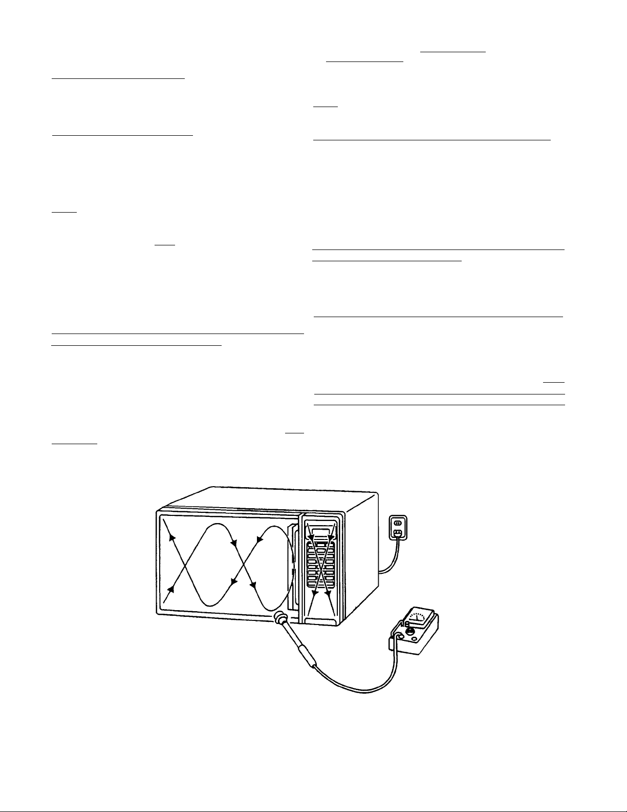
In the area emitting the highest reading, switch the meter
to SLOW RESPONSE, and take a reading for minimum of
three (3) seconds. We recommended the pattern outline
shown below when the door surface is surveyed.
On every service calls, check for microwave energy
emission, must be made according to the following manner.
MeasurMeasur
Measur
MeasurMeasur
Measurement must be made with the microwave oven
operating at its maximum output and containing a load of
275±15 milliliters of tap water initially at 20
±9oF) placed within the cavity at the center.
NOTENOTE
NOTE : The water container must be a 600 milliliter beaker
NOTENOTE
A properly operating door and seal assembly will normally
register emission on greater than 4mW/cm2 to allow for
measurement uncertainty with the cooking shelf or tray in
place.
All repairs must be performed in such a manner All repairs must be performed in such a manner
All repairs must be performed in such a manner
All repairs must be performed in such a manner All repairs must be performed in such a manner
micrmicr
micr
micrmicr
Follow the instructions supplied with a detector being used
and performed an R.F. emission test around the door front
and edges and all edges and vent of the outer case. The
cabinet (wrapper) must be in place and the oven fully
assembled.
When performing emission survey, with the meter on FAST
RESPONSE the movement of a detector probe shall not
exceed one (1) inch per second.
ement of enerement of ener
ement of ener
ement of enerement of ener
and made of an electrically none conductive
material such as glass or plastic.
The cook tray must be in place when measuring
emission.
owave enerowave ener
owave ener
owave enerowave ener
gy emissiongy emission
gy emission
gy emissiongy emission
gy emission argy emission ar
gy emission ar
gy emission argy emission ar
e minimal.e minimal.
e minimal.
e minimal.e minimal.
o±5o
celsius (68
thatthat
that
thatthat
NOTENOTE
NOTE : Periodically check to be sure that the probe tip is
NOTENOTE
not worn or dirty.
The following U.S. standard applies to microwave ovens :
21 CFR 1030.10, Performance Standard for Microwave
Ovens.
It requires that the power density of the microwave
radiation emitted by a microwave oven shall not exceed
five (5) milliwatts per square centimeter at any point 5
centimeter (about 2 inches) or more from the external
surface of the oven.
All microwave ovens exceeding the emission level of
4mW/cm
microwave ovens and the manufacturer immediately and
the owner should be told not to use the microwave oven
until it has been repaired completely.
If a microwave oven is found to operate with the door open,
report to Dept. of Service, the manufacturer and CDRH*
immediately. Also tell the owner not to use the oven.
*CDRH : Center for Device and Radiological Health.
The interlock monitor switch acts as the final safety switch
protecting the customer from microwave radiation. If the
interlock monitor switch operates to blow the fuse with
interlocks failed, you must replace all interlock switches
primary and secondary interlock switches and the monitor
switch with new ones because the contacts of those
interlock switches may be melted and welded together.
2
must be reported to Dept. of Service for
- i -

- TABLE OF CONTENTS -
Specifications .................................................................. 1
Power Output Measurement ........................................... 1
Circuit Diagram ............................................................... 2
1. SPECIFICA1. SPECIFICA
1. SPECIFICA
1. SPECIFICA1. SPECIFICA
Rated Power Consumption ... 1650W.
Microwave Output ................. 1050W.
Frequency .............................. 2,450MHz±50MHz.
Power Supply ......................... 120V±12V, 60Hz.
Rated Current ........................ 14.3 Amp.
Safety Devices ...................... Thermal Fuse open at
Timer ...................................... Electronic Digital, up to
Overall Dimensions ............... 215/8”(W) x 183/16”(D) x 121/2”(H).
Oven Cavity Size ................... 1412/16”(W) x 169/16”(D) x 95/16”(H).
Turn Table Diameter ............... 125/8”
Effective Capacity of
Oven Cavity ........................... 1.4 Cubic Feet.
Net Weight ............................ Approx. 39.5 Lbs.
TIONSTIONS
TIONS
TIONSTIONS
o
F (167oC) for Cavity.
331
Thermal Protector open at
o
275
F (135oC) for Magnetron,
Fuse (Cartridge Type 20A),
Primary Interlock Switch,
Door Sensing Switch and
Relay 2.
Interlock Monitor Switch.
99min. 99 sec.
Test Procedures ...................................................... 3
Exploded View and Parts List ................................ 4 ~ 9
Overall Circuit Diagram .......................................... 10
(C) 1. Set cooking time to two (2) minutes. (“2 00”
appears in display)
2 . Touch “START” key and operate oven for exactly
two (2) minutes.
(D) 1. Take out the two bowls at once.
2 . Stir both water with thermometer and measure the
water temperature rise respectively.
(E) 1 . Get temperature rise by calculation the difference
(water temperature after cooking minus initial
temperature) in each bowl.
2 . Then calculate average value(t) of both temperature
rises in degrees centigrade.
3. Then work out :
Power Output (watt) = 70 x ∆t
2. POWER OUTPUT MEASUREMENT2. POWER OUTPUT MEASUREMENT
2. POWER OUTPUT MEASUREMENT
2. POWER OUTPUT MEASUREMENT2. POWER OUTPUT MEASUREMENT
NOTENOTE
NOTE
NOTENOTE
The Power Output specification 1050W on this model
is measured with IEC measurement. The Power Output
is measured with two (2) liters water is equivalent to
1050W in measurement with IEC, when measured with
the following Power Output.
(A) 1 . Fill two test bowls with each 1 liter water respectively.
2 . Use accurate thermometer and measure each
water temperature respectively.
(B) Place the two bowls on glass turntable.
Where ∆t is an Average Temperature Rise in degrees
centigrade.
(F) Power Output shall be in the following range :
Average Microwave
Temperature Rise Power Output
Minimum
24.3oF (13.5oC) 945W
Maximum
31.1oF (17.3oC) 1211W
(G) Power Output will be influenced by line voltage of
power supply. Consequently, correct Power Output
must be measured within 120V AC ± 1 volt while
unit is operating.
- 1 -
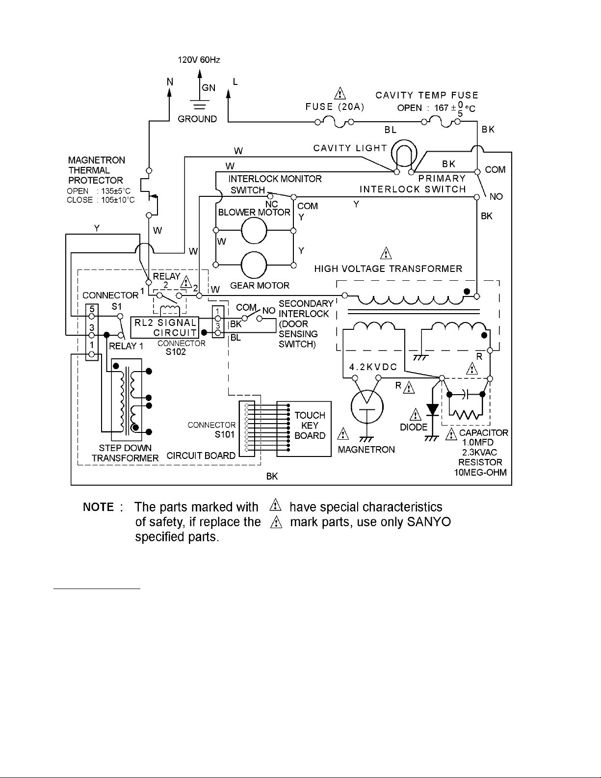
3. CIRCUIT DIAGRAM3. CIRCUIT DIAGRAM
3. CIRCUIT DIAGRAM
3. CIRCUIT DIAGRAM3. CIRCUIT DIAGRAM
WIRING COLOR
O : ORANGE B K : BLACK
R : RED BL : BLUE
W : WHITE Y : YELLOW
- 2 -
Figure 1Figure 1
Figure 1
Figure 1Figure 1
4. TEST PROCEDURES4. TEST PROCEDURES
4. TEST PROCEDURES
4. TEST PROCEDURES4. TEST PROCEDURES
COMPONENT COMPONENT
COMPONENT
COMPONENT COMPONENT
TOUCH KEY
BOARD
065
1
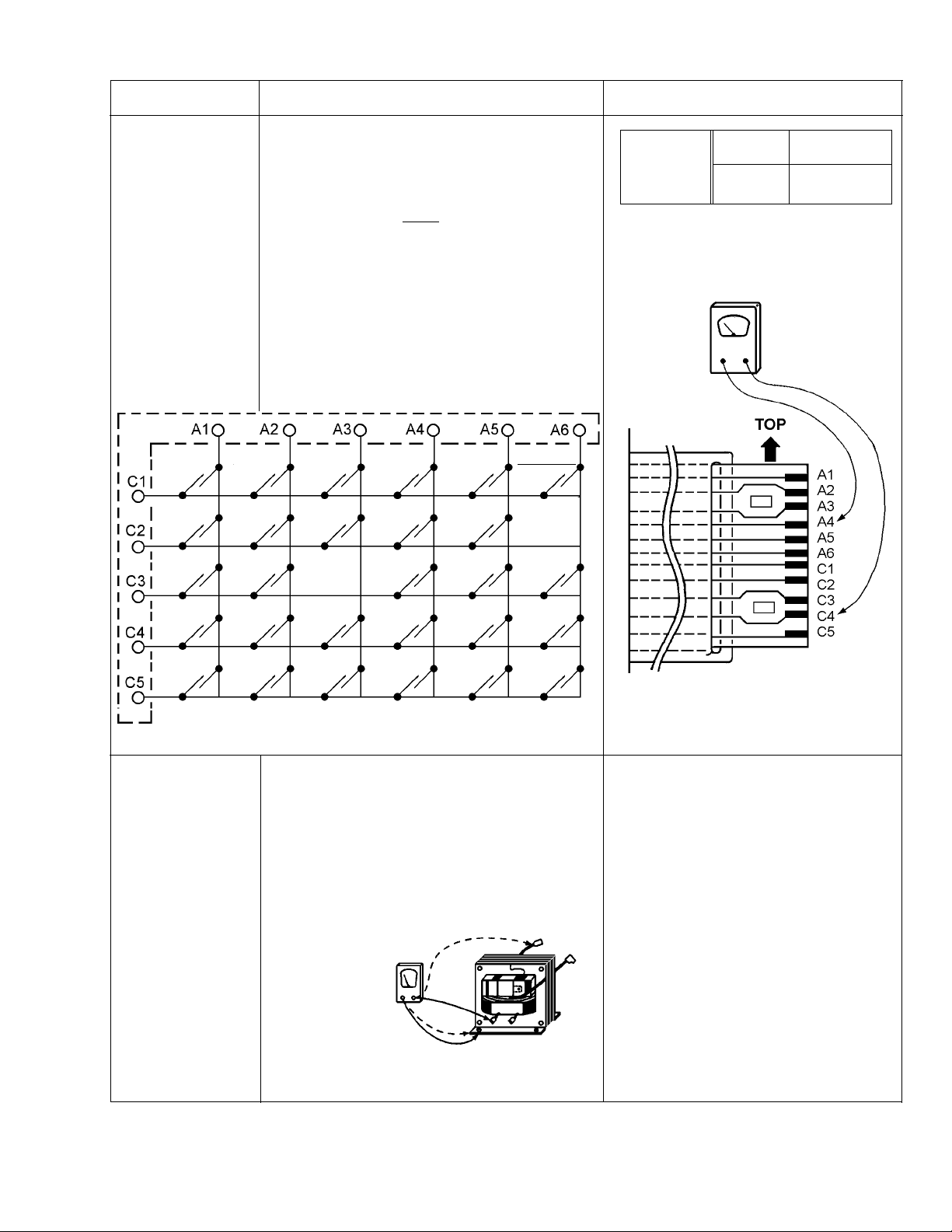
CHECKOUT PROCEDURE CHECKOUT PROCEDURE
CHECKOUT PROCEDURE
CHECKOUT PROCEDURE CHECKOUT PROCEDURE
Measure the resistance between terminals of
FPC connector after removing it from S101.
(Figure 2).
NOTE NOTE
NOTE
NOTE NOTE
- When reconnecting the FPC connector, make When checking “START” key, connect
sure the holes on the connector are properly Ohm-Meter as illustration below.
inserted in hooks of the plastic fastener in S101.
MAMA
TOTAL
DEFROST
7
TRIX CIRCUIT FORTRIX CIRCUIT FOR
MA
TRIX CIRCUIT FOR
MAMA
TRIX CIRCUIT FORTRIX CIRCUIT FOR
TOUCH KEY BOARD TOUCH KEY BOARD
TOUCH KEY BOARD
TOUCH KEY BOARD TOUCH KEY BOARD
FPC CONNECTORFPC CONNECTOR
FPC CONNECTOR
FPC CONNECTORFPC CONNECTOR
POWER
LEVEL
QUICK
ON
SOUP /
BEVERAGE
POTATO
MORE +
LESS -
Resistance
value
Ohm-MeterOhm-Meter
Ohm-Meter
Ohm-MeterOhm-Meter
RESUL RESUL
RESUL
RESUL RESUL
When When not
touched touched
Less than More than
1K Ohms 1 MEG Ohms
TT
T
TT
2
3
4
HIGH-VOLTAGE
TRANSFORMER
8
9
STOP /
CLEAR
PIZZA
SLICE
FRESH
VEGETABLE
1) Measure the resistance : Normal readings :
With an Ohm-Meter on R x 1 scale.
a. Primary winding : Approximately 0.3 Ohms.
b. Filament winding : Less than 1 Ohm.
c. Secondary winding : Approximately 74.2 Ohms.
2) Measure the resistance : Normal readings :
With an Ohm-Meter on highest scale.
a. Primary winding to ground : Infinite Ohms.
b. Filament winding to ground : Infinite Ohms.
Ohm-MeterOhm-Meter
Ohm-Meter
Ohm-MeterOhm-Meter
QUICK
DEFROST
START
CLOCK POPCORN
FROZEN
ENTREE
FROZEN
VEGETABLE
KITCHEN
TIMER
ADD
30 SEC
CUSTOM
PROGRAMS
TERMINALS OF FPC CONNECTORTERMINALS OF FPC CONNECTOR
TERMINALS OF FPC CONNECTOR
TERMINALS OF FPC CONNECTORTERMINALS OF FPC CONNECTOR
Figure 2Figure 2
Figure 2
Figure 2Figure 2
Note Note
Note : Remove varnish of
Note Note
measured point.
- 3 -
Figure 3Figure 3
Figure 3
Figure 3Figure 3
5.5.
EXPLODED VIEW AND PEXPLODED VIEW AND P
5.
EXPLODED VIEW AND P
5.5.
EXPLODED VIEW AND PEXPLODED VIEW AND P
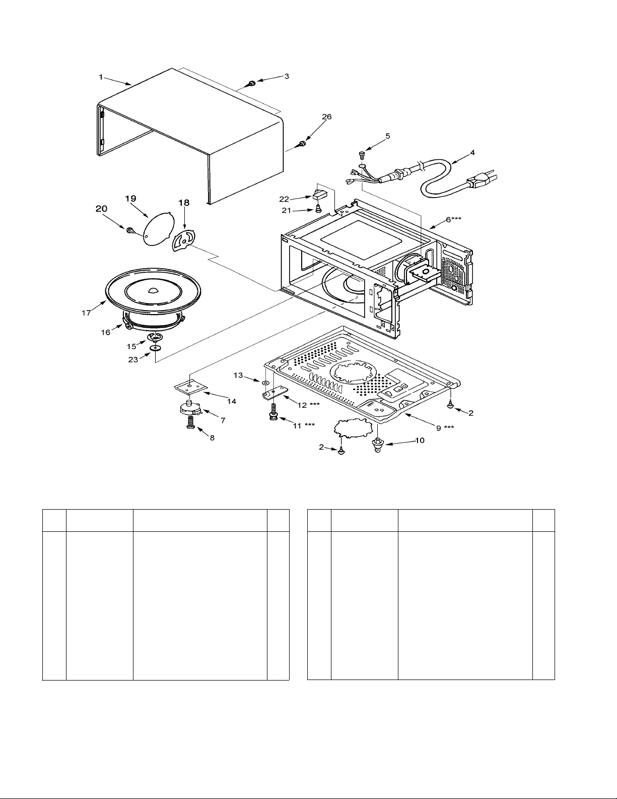
CAVITY PARTS
ARAR
AR
ARAR
TS LISTTS LIST
TS LIST
TS LISTTS LIST
* * * ALL SERVICE ON MICROWAVE OVENS SHOULD BE PERFORMED BY A QUALIFIED TECHNICIAN USING
APPROVED TESTING EQUIPMENT. CUSTOMERS SHOULD NOT ATTEMPT TO REPLACE PARTS IDENTIFIED
BY A TRIPLE ASTERISK (***).
Key
No.
Part No. Description Q’ty
1 617 228 8949 Cabinet 1
2 411 082 5201 SCR TPG TRS 4 x 10 Z1 6
3 411 160 6007 SCR TPG TRS + SRT 4 x 10 Z1 2
4 617 235 3234 Power Cord 1
5 411 160 6106 SCR S-T TRS + SRT 4 x 10 Z1 1
6 617 228 0271 Oven Cavity*** (Not Service Part) 1
7 617 124 1068 Gear Motor 1
8 411 010 5808 SCR EVR PAN 4 x 10 Z1 2
9 617 124 6391 Bottom Plate*** (Not Service Part) 1
10 617 221 6089 Plastic Foot with Canoe Clip 4
11 411 011 0802 Bolt Hex + SW + W5 x 14 Z1*** 2
12 617 223 3116 Hinge, Lower*** 1
13 411 089 2500 Washer F 5 x 10 x 0.8 1
NoteNote
Note : Screws securing Cabinet cannot be removed by regular screwdriver.
NoteNote
KEY NO. 26. SPECIAL SCREW REQUIRES SPECIAL DRIVER
(PART NO. 617 209 3734) OR SPECIAL BIT (PART NO. 617 209 3741)
Key
No.
Part No. Description Q’ty
14 617 120 8481 Insulation Sheet 1
15 617 220 9401 Turn Table Shaft 1
16 617 199 1314 Roller Base Assy 1
17 617 201 2704 Rotating Tray 1
18 617 227 1873 Antenna Complete 1
19 617 235 2435 Cavity Cover 1
20 411 069 1707 SCR TPG TRS 4 x 6 DA 1
21 411 006 6604 SCR TPG PAN 3 x 6 Z1 1
22 617 200 0381 Thermal Fuse 167oC1
23 617 080 5315 Special Washer 1
24
25
26 617 229 9013 Special Screw 2
- 4 -
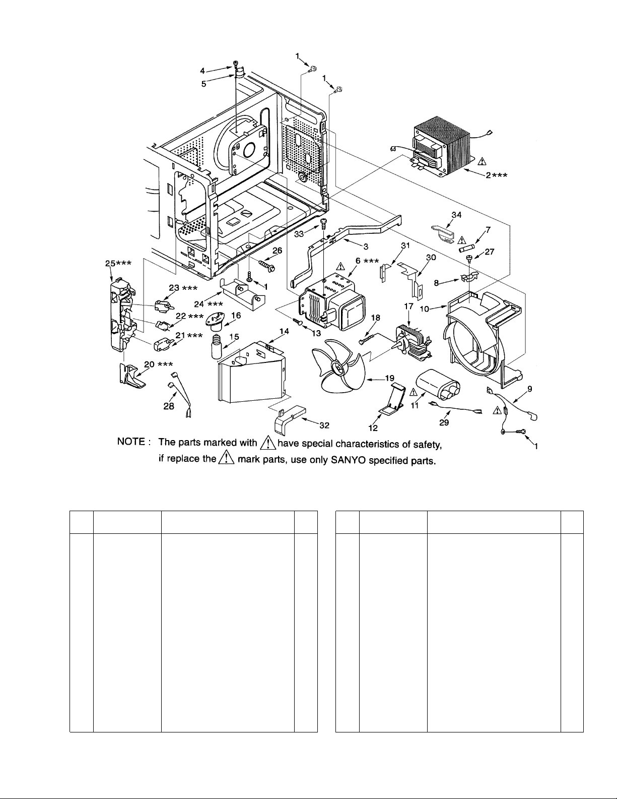
SWITCHES AND MICROWAVE PARTS
*** ALL SERVICE ON MICROWAVE OVENS SHOULD BE PERFORMED BY A QUALIFIED TECHNICIAN USING
APPROVED TESTING EQUIPMENT. CUSTOMERS SHOULD NOT ATTEMPT TO REPLACE PARTS IDENTIFIED
BY A TRIPLE ASTERISK (***).
Key
No.
Part No. Description Q’ty
1 411 082 5201 SCR TPG TRS 4 x 10 Z1 9
2 617 235 3319 H.V. T ransformer,*** N6T-V3405 1
120V 60Hz
3 617 162 1945 Stay, Cavity & Magnetron 1
4 411 006 6604 SCR TPG PAN 3 x 6 Z1 1
5 617 129 1001 Thermostat, Magnetron 135oC1
6 415 002 6101 Magnetron, 2M219H(B)A-*** 1
7 423 020 3408 Fuse, 125V 20A 1
8 617 235 3302 Fuse Holder 1
9 617 221 3606 Lead Wire Ass’y (including Diode) 1
10 617 162 1990 Blower Base 1
11 617 235 3326 H.V Capacitor including Resistor, 1
1.0uf 2.3KV
12 617 182 2373 Capacitor Band 1
13 411 011 5609 Bolt Hex 4 x 10 Z1 4
14 617 235 1551 Duct, Mag. Exhaust 1
15 617 005 5147 Lamp, 120V 20W 1
16 617 230 2713 Lamp Socket 1
17 617 197 7417 Blower Motor 1
Key
No.
Part No. Description Q’ty
18 411 082 5201 SCR TPG TRS 4 x 10 Z1 2
19 617 196 8507 Blower Fan 1
20 617 245 6256 Latch Lever*** 1
21 617 221 4078 Micro Switch,*** Primary Interlock 1
AM51630C53F2
22 617 221 4061 Micro Switch,*** Interlock Monitor 1
AM50620C53
23 617 221 4078 Micro Switch,*** Door Sensing 1
AM51630C53F2
24 617 124 1198 Latch Lever,*** 1
25 617 245 6096 Lever Stopper*** 1
26 411 102 5907 SCR ETG TRS 4 x 10 N2 2
27 411 129 5805 SCR TPG BIN 3 x 10 Z1 1
28 617 226 2987 Harness, Door Sensing 1
29 617 124 2300 Lead Wire Ass’y 1
30 617 235 3722 Duct, (MQ In) 1
31 617 235 3739 Duct, (MQ In) 1
32 617 235 2534 Duct, (H.V.Trans.) 1
33 411 102 5808 SCR ETG TRS 4 x 10 Z1 1
34 617 235 4132 Duct, (Fuse) 1
- 5 -
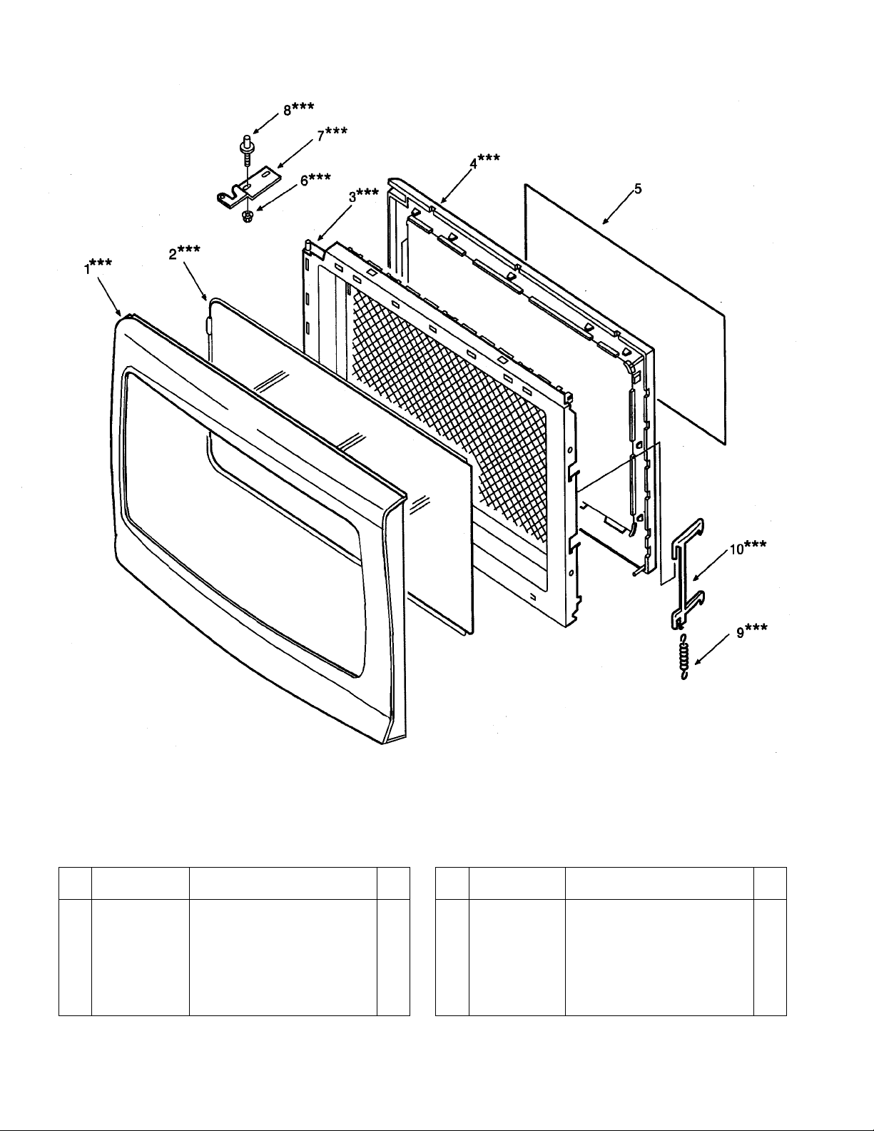
DOOR PARTS
* * * ALL SERVICE ON MICROWAVE OVENS SHOULD BE PERFORMED BY A QUALIFIED TECHNICIAN USING
APPROVED TESTING EQUIPMENT. CUSTOMERS SHOULD NOT ATTEMPT TO REPLACE PARTS IDENTIFIED
BY A TRIPLE ASTERISK (***).
Key
No.
Part No. Description Q’ty
1 617 235 4125 Door Cover*** 1
2 617 232 3909 Door Panel*** 1
3 617 227 6533 Door Main Frame*** (Also 1
order Door Sheet when replacing
Door Main Frame)
4 617 227 1118 Choke Dielectric*** 1
Key
No.
Part No
5 617 228 0295 Door Sheet 1
6 411 054 1903 Nut Hex + Flg W / SRT 5*** 2
7 617 223 3109 Hinge, Upper*** 1
8 411 011 0802 Bolt Hex + SW + W 5 x 14*** 2
9 617 101 1494 Spring*** 1
10 617 228 6068 Door Latch*** 1
. Description Q’ty
- 6 -
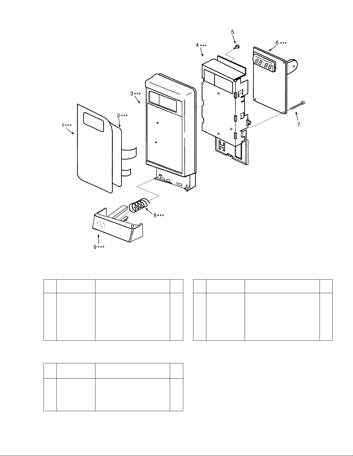
CONTROL PANEL PARTS
* * * ALL SERVICE ON MICROWAVE OVENS SHOULD BE PERFORMED BY A QUALIFIED TECHNICIAN USING
APPROVED TESTING EQUIPMENT. CUSTOMERS SHOULD NOT ATTEMPT TO REPLACE PARTS IDENTIFIED
BY A TRIPLE ASTERISK (***).
Key
No.
Part No. Description Q’ty
1 617 235 1636 Control Sheet*** (Also order 1
Touch Key Board when replacing
Control Sheet)
2 617 234 4119 Touch Key Board*** (Also order 1
Control Sheet when replacing
Touch Key Board)
3 617 232 3923 Control Frame*** 1
Key
No.
Part No. Description Q’ty
4 617 228 0752 Control Base*** 1
5 411 160 6205 SCR TPG TRS+SRT 4 x 10 Z1 1
6 617 230 8371 Power & Control Circuit Board*** 1
7 411 129 5805 SCR TPG BIN 3 x 10 Z1 2
8 617 080 9559 Spring, Door Release Lever*** 1
9 617 232 3916 Door Release Lever*** 1
PRINTED MATTER (Items Not Illustrated)
Key
No.
Part No. Description Q’ty
617 235 3418 Operating Instructions 1
(English / Spanish)
617 235 4293 Carton Box Complete 1
617 235 1483 Name Plate 1
- 7 -

CONTROL CIRCUIT BOARDCONTROL CIRCUIT BOARD
CONTROL CIRCUIT BOARD
CONTROL CIRCUIT BOARDCONTROL CIRCUIT BOARD
(Part No.
617 230 8371617 230 8371
617 230 8371)
617 230 8371617 230 8371
41
4141
4141
9
99
99
00
0000
0000
- 8 -
CONTROL CIRCUIT BOARDCONTROL CIRCUIT BOARD
CONTROL CIRCUIT BOARD
CONTROL CIRCUIT BOARDCONTROL CIRCUIT BOARD
(Part No.
617 230 8371617 230 8371
617 230 8371)
617 230 8371617 230 8371
Key No. Order Part No. Description Q’ty
INTEGRATED CIRCUIT
IC11 409 488 3907 IC LM8887-1P44N. 1
TRANSISTORS
Q901 405 138 8506 TR FMA9A. 1
Q103 405 011 8401 2SC1740S-Q-TP. 1
Q101,102 405 137 5803 DTA123YSA-TP. 2
Q105,106 405 004 3000 2SA564A-Q-TP. 2
DIODES
D11 407 012 0200 1N4002-TP. 1
D101~106 407 012 4406 1SS133-T77. 7
108
ZD101 407 132 2306 HZS3.9ENB2. 1
ZD11 407 056 8507 RD5.1ESB2. 1
CAPACITORS
C104, 105, 403 069 1207 Ceramic, 1000PK, 3
108 +-5%, 50V.
C103, 106, 403 069 8305 Ceramic, 0.01mfd, 3
107 +-5%, 50V.
C101 403 147 8807 Electrolytic, 1mfd, 1
+-20%, 50V.
C12 403 147 8609 Electrolytic, 47mfd, 1
+-20%, 10V.
C11 403 152 7208 Electrolytic, 1000mfd, 1
+-20%, 25V.
RESISTORS.
R901, 906, 401 037 5608 MT-Glaze, 10K ohms 5
909, 911, +-1%, 10W.
913
R910 401 037 6704 MT-Glaze, 1.2K ohms 1
+-1%, 10W
R903 401 038 3603 MT-Glaze, 3.3K ohms 1
+-1%, 10W.
R912, 914 401 038 5003 MT-Glaze, 390 ohms 2
+-1%, 10W
R902, 905, 401 038 6406 MT-Glaze, 4.7K ohms 4
907, 908 +-1%, 10W.
R904 401 039 0304 MT-Glaze, 820 ohms 1
+-1%, 10W.
Key No. Order Part No. Description Q’ty
RESISTORS.
R106 401 012 4404 Carbon, 100 ohms 5
11 ~ 14 +-5%, 1/4W.
R101, 112 401 012 5609 Carbon, 1K ohms 2
R118 401 013 5202 Carbon, 1.2K ohms 1
R56, 57 401 013 6308 Carbon, 12K ohms 2
R105 401 016 4707 Carbon, 22K ohms 1
R107, 108 401 016 9603 Carbon, 27 ohms 2
R109 401 018 2701 Carbon, 330 ohms 1
R51, 54, 401 020 2805 Carbon, 47K ohms 4
103, 104 +-5%, 1/4W.
RESISTOR BLOCK
RB101 617 010 3558 Resistor Network 1
RB902 402 080 7700 MT-Glaze, 10K x 4 1
RB901 402 083 2108 MT-Glaze, 4.7K x 4 1
MISCELLANEOUS
BZ1 420 000 6800 Buzzer, PKM22EPT. 1
VST1 407 118 5505 Varistor ENC 471D-10A. 1
LCD1 617 234 4737 Display Tube. 1
LCD1 617 229 0843 Control Plate. 1
RL1 617 201 3978 Relay, G5N-1A-DC12. 1
RL2 617 201 3954 Relay, G5G-1ADC12. 1
RS1 617 128 3372 Ceramic Oscillator. 1
S 1 617 180 5888 Connector. 1
S101 617 126 8959 Connector. 1
S102 617 226 6510 Connector. 1
PT1 617 230 4984 Step-Down Transformer. 1
2 617 232 8157 Part Base. 1
3 617 232 8171 Part Base. 1
LED1 ~ 4 407 217 3808 LED AAPY1211C-TR 4
JB1, 2 617 132 5744 Noise Filter. 2
J9
13 617 079 4299 Jumper. 7
~
16, 17
J101~109 617 079 4237 Jumper. 9
+-5%, 1/4W.
+-5%, 1/4W.
+-5%, 1/4W.
+-5%, 1/4W.
+-5%, 1/4W.
+-5%, 1/4W.
P6K-P410
- 9 -
 Loading...