

Sanyo EMS9000SSS860289 Schematic
File No :File No :
File No :
File No :File No :
SUPPLEMENT OF SUPPLEMENT OF
SUPPLEMENT OF
SUPPLEMENT OF SUPPLEMENT OF
SER SER
SER
SER SER
VICE MANUALVICE MANUAL
VICE MANUAL
VICE MANUALVICE MANUAL
Micr Micr
Micr
Micr Micr
owave Ovenowave Oven
owave Oven
owave Ovenowave Oven
Pr Pr
Pr
Pr Pr
See the Service Manual of EM-S8000BS (SM-860278)
except the items described in this Service Manual.
EM-S9000S EM-S9000S
EM-S9000S
EM-S9000S EM-S9000S
oduct Code No.oduct Code No.
oduct Code No.
oduct Code No.oduct Code No.
(U.S.A.)(U.S.A.)
(U.S.A.)
(U.S.A.)(U.S.A.)
437 500 02437 500 02
437 500 02
437 500 02437 500 02
CAUTIONCAUTION
CAUTION
CAUTIONCAUTION
WW
ARNING TO SERARNING TO SER
W
ARNING TO SER
WW
ARNING TO SERARNING TO SER
VICE TECHNICIANSVICE TECHNICIANS
VICE TECHNICIANS
VICE TECHNICIANSVICE TECHNICIANS
PRECAUTIONS TO BE OBSERVED BEFORE AND DURING
SERVICING TO AVOID POSSIBLE EXPOSURE TO
EXCESSIVE MICROWAVE ENERGY
(a) Do not operate or allow the oven to be operated with the door open.
(b) Make the following safety checks on all ovens to be serviced before activating the magnetron or other
microwave source, and make repairs as necessary :
(1) Interlock operation, (2) proper door closing, (3) seal and sealing surfaces (arcing, wear, and other damage),
(4) damage to or loosening of hinges and latches, (5) evidence of dropping or abuse.
(c) Before turning on microwave power for any service test or inspection within the microwave generating
compartments, check the magnetron, wave guide or transmission line, and cavity for proper alignment, integrity,
and connections.
(d) Any defective or misadjusted components in the interlock, monitor, door seal, and microwave generation and
transmission systems shall be repaired, replaced, or adjusted by procedures described in this manual before
the oven is released to the owner.
(e) A microwave leakage check to verify compliance with the Federal per formance standard should be performed
on each oven prior to release to the owner.
REFERENCE NO. SS-860289
CAUTIONCAUTION
CAUTION
CAUTIONCAUTION
For micrFor micr
For micr
For micrFor micr
On every service calls, check for microwave energy
emission, must be made according to the following manner.
MeasurMeasur
Measur
MeasurMeasur
Measurement must be made with the microwave oven
operating at its maximum output and containing a load of
275±15 milliliters of tap water initially at 20
±9oF) placed within the cavity at the center.
NOTE : The water container must be a 600 milliliter beaker
A properly operating door and seal assembly will normally
register emission on greater than 4mW/cm
measurement uncertainty with the cooking shelf or tray in
place.
All repairs must be performed in such a manner All repairs must be performed in such a manner
All repairs must be performed in such a manner
All repairs must be performed in such a manner All repairs must be performed in such a manner
micrmicr
micr
micrmicr
Follow the instructions supplied with a detector being used
and performed an R.F. emission test around the door front
and edges and all edges and vent of the outer case. The
cabinet (wrapper) must be in place and the oven fully
assembled.
When performing emission survey, with the meter on FAST
RESPONSE the movement of a detector probe shall not
exceed one (1) inch per second.
owave enerowave ener
owave ener
owave enerowave ener
ement of enerement of ener
ement of ener
ement of enerement of ener
and made of an electrically none conductive
material such as glass or plastic.
The cook tray must be in place when measuring
emission.
owave enerowave ener
owave ener
owave enerowave ener
gy emissiongy emission
gy emission
gy emissiongy emission
gy emissiongy emission
gy emission
gy emissiongy emission
gy emission argy emission ar
gy emission ar
gy emission argy emission ar
e minimal.e minimal.
e minimal.
e minimal.e minimal.
o±5o
2
celsius (68
to allow for
thatthat
that
thatthat
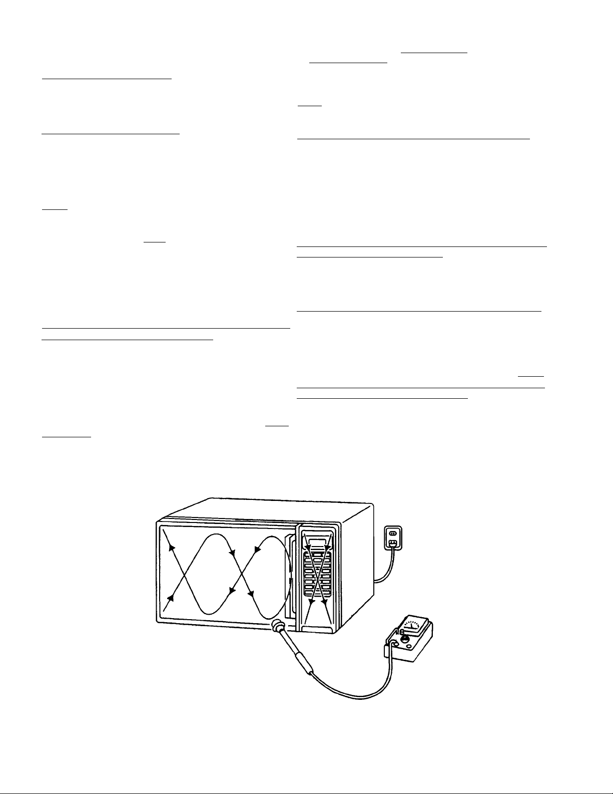
In the area emitting the highest reading, switch the meter
to SLOW RESPONSE, and take a reading for minimum of
three (3) seconds. We recommended the pattern outline
shown below when the door surface is surveyed.
NOTE : Periodically check to be sure that the probe tip is
not worn or dirty.
The following U.S. standard applies to microwave ovens :
21 CFR 1030.10, Performance Standard for Microwave
Ovens.
It requires that the power density of the microwave
radiation emitted by a microwave oven shall not exceed
five (5) milliwatts per square centimeter at any point 5
centimeter (about 2 inches) or more from the external
surface of the oven.
All microwave ovens exceeding the emission level of
4mW/cm2 must be reported to Dept. of Service for
microwave ovens and the manufacturer immediately and
the owner should be told not to use the microwave oven
until it has been repaired completely.
If a microwave oven is found to operate with the door open,
report to Dept. of Service, the manufacturer and CDRH*
immediately. Also tell the owner not to use the oven.
*CDRH : Center for Device and Radiological Health.
The interlock monitor switch acts as the final safety switch
protecting the customer from microwave radiation. If the
interlock monitor switch operates properly and the door
interlocks switch fails, the fuse will blow. If this happens,
all interlock switches must be replaced. The contacts of
the interlock switches may be welded together.
- i -

- TABLE OF CONTENTS -
Specifications .................................................................. 1
Power Output Measurement ........................................... 1
Circuit Diagram ............................................................... 2
1. SPECIFICA1. SPECIFICA
1. SPECIFICA
1. SPECIFICA1. SPECIFICA
Rated Power Consumption ... 1630W.
Microwave Output ................. 1000W.
Frequency .............................. 2,450MHz±50MHz.
Power Supply ......................... 120V±12V, 60Hz.
Rated Current ........................ 14 Amp.
Safety Devices ...................... Thermal Fuse open at 332oF
Timer ...................................... Electronic Digital, up to
Overall Dimensions ............... 297/8”(W) x 141/8”(D) x 17”(H)
Oven Cavity Size ................... 191/4”(W) x 131/2”(D) x 97/8”(H)
Turn Table Diameter ............... 1013/16”
Effective Capacity of
Oven Cavity ........................... 1.5 Cubic Feet.
Net Weight ............................ Approx. 61.5 Lbs.
TIONSTIONS
TIONS
TIONSTIONS
o
C) for Cavity & Bottom.
(167
Thermal Protector open at
o
252
F (122oC) for Magnetron.
Thermostat close at 140oF
(60oC) for Hood Fan.
Fuse (Cartridge Type 20A)
Primary Interlock Switch,
Door Sensing Switch and
Relay 2.
Interlock Monitor Switch.
99min. 99 sec.
Exploded View and Parts List ................................ 3 ~ 10
Overall Circuit Diagram .......................................... 11 ~ 12
(C) 1 . Set cooking time to two (2) minutes. (“2 00”
appears in display)
2 . Touch “START” key and operate oven for exactly
two (2) minutes.
(D) 1 . Take out the two bowls at once.
2 . Stir both water with thermometer and measure the
water temperature rise respectively.
(E) 1 . Get temperature rise by calculation the difference
(water temperature after cooking minus initial
temperature) in each bowl.
2 . Then calculate average value(t) of both temperature
rises in degrees centigrade.
3. Then work out :
Power Output (watt) = 70 x ∆t
Where ∆t is an Average Temperature Rise in degrees
centigrade.
2. POWER OUTPUT MEASUREMENT2. POWER OUTPUT MEASUREMENT
2. POWER OUTPUT MEASUREMENT
2. POWER OUTPUT MEASUREMENT2. POWER OUTPUT MEASUREMENT
NOTENOTE
NOTE
NOTENOTE
The Power Output specification 1000W on this model
is measured with IEC measurement. The Power Output
is measured with two (2) liters water is equivalent to
1000W in measurement with IEC, when measured with
the following Power Output.
(A) 1. Fill two test bowls with each 1 liter water respectively.
2 . Use accurate thermometer and measure each
water temperature respectively.
(B) Place the two bowls on glass turntable.
(F) Power Output shall be in the following range :
Average Mi crowave
Temperature Rise : Power Output :
Minimum
23.0oF(12.8oC) 896W
Maximum
28.3oF(15.7oC) 1099W
(G) Power Output will be influenced by line voltage of
power supply. Consequently, correct Power Output
must be measured within 120V AC ± 1 volt while
unit is operating.
- 1 -
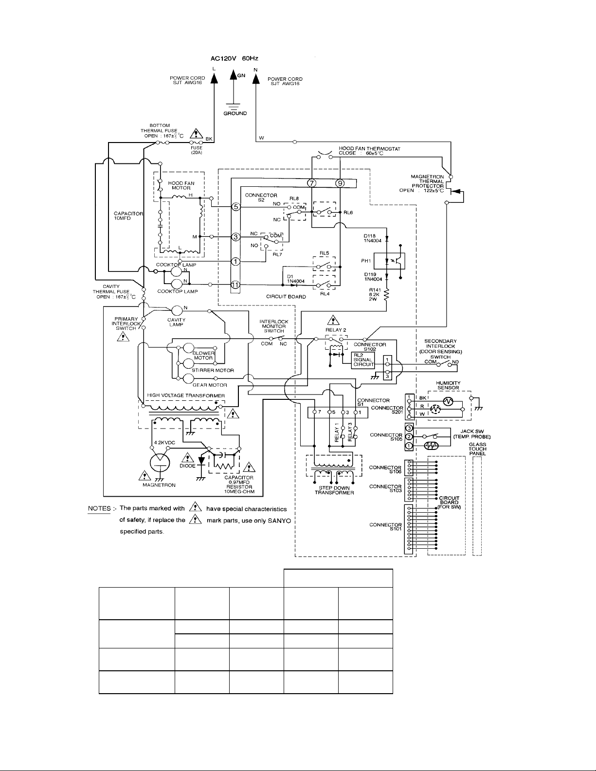
3. CIRCUIT DIAGRAM
Figure 1Figure 1
Figure 1
KCOLRETNIYRADNOCES
YRAMIRP
•
EDAMHCTIWS
NOITIDNOC
NEPOROOD
ESOLCROOD
KCOLRETNI
HCTIWS
MOCMOCMOCMOC
ONCNONON
•••
KCOLRETNI
ROTINOM
HCTIWS
ROOD
GNISNES
HCTIWS
2YALER
•
Figure 1Figure 1
- 2 -
4.4.
EXPLODED VIEW AND PEXPLODED VIEW AND P
4.
EXPLODED VIEW AND P
4.4.
EXPLODED VIEW AND PEXPLODED VIEW AND P
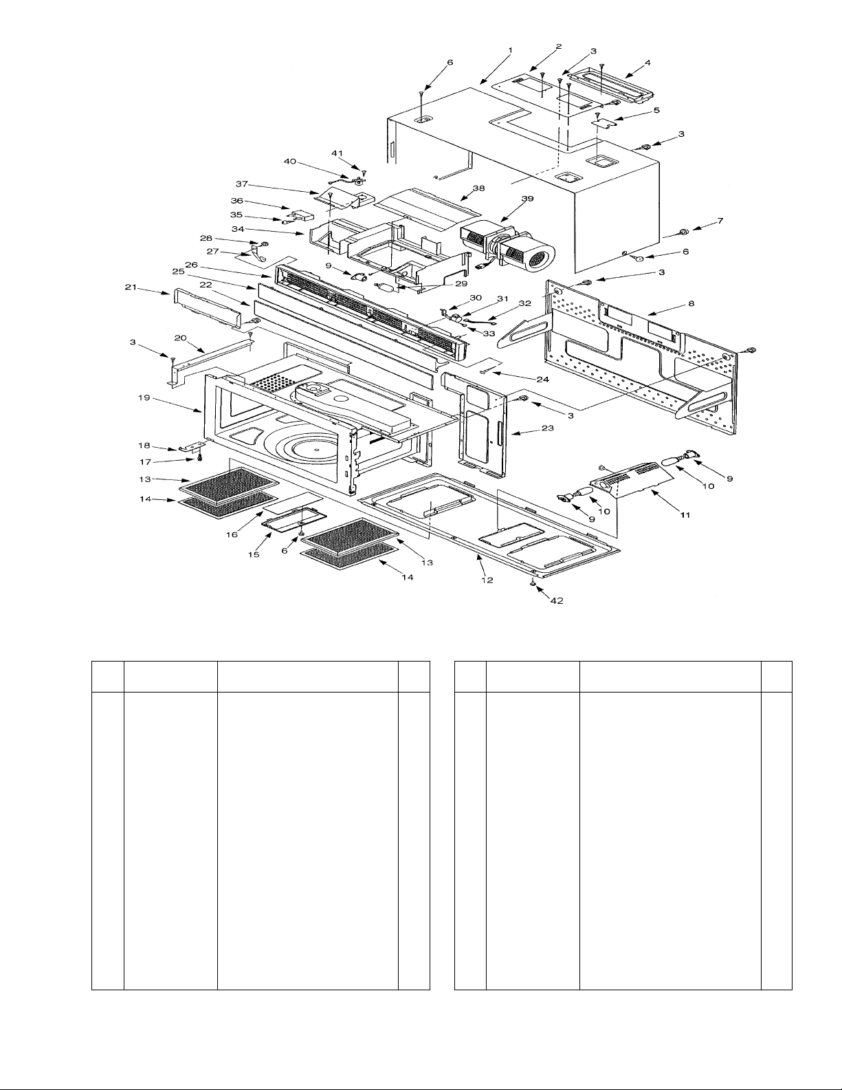
CAVITY PARTS
ARAR
AR
ARAR
TS LISTTS LIST
TS LIST
TS LISTTS LIST
* * * ALL SERVICE ON MICROWAVE OVENS SHOULD BE PERFORMED BY A QUALIFIED TECHNICIAN USING
APPROVED TESTING EQUIPMENT. CUSTOMERS SHOULD NOT ATTEMPT TO REPLACE PARTS IDENTIFIED
BY A TRIPLE ASTERISK (***).
Key
No.
Part No. Description Q’ty
1 617 224 9919 Cabinet 1
2 617 222 1960 Cabinet BCT. 1
3 411 082 5201 SCR TPG TRS 4 x 10 Z1 51
4 617 222 2653 Damper Assy 1
5 617 222 1977 Frame Bracket, Power Cord 1
6 411 128 5806 SCR TPG TRS 4 x 10 C2 4
7 411 160 6007 SCR TPG TRS + SRT 4 x 10 1
8 617 221 3286 Stay Plate, Rear (Not Service Part) 1
9 617 124 1280 Lamp Socket 3
10 617 222 2011 Lamp, 130V 40W 2
11 617 221 9950 Lamp BCT 1
12 617 220 9579 Bottom Plate (Not Service Part) 1
13 617 222 2691 Filter Assy, Black 2
14 617 222 2684 Filter Assy, Silver 2
15 617 222 0604 Cover, Hood Lamp 1
16 617 222 1991 Lamp Plate, Glass 1
17 411 011 0802 Bolt Hex + SW + W5 x 14 2
18 617 222 1113 Hinge Assy, Lower 1
19 617 229 4216 Cavity Assy (Not Service Part) 1
20 617 222 2219 Stay Plate, Left 1
21 617 221 9943 Cavity Rear Plate, Left 1
Key
No.
Part No. Description Q’ty
22 617 225 0502 Ornament Plate 1
23 617 221 9936 Cavity Rear Plate, Right 1
24 411 073 0604 SCR TPG PAN 3 x 30 Z1 2
25 617 225 0069 Louver 1
26 617 225 0052 Grille 1
27 617 222 2356 Spring 2
28 411 129 5805 SCR TPG BIN 3 x 10 Z1 2
29 617 222 2400 Lamp, 125V 30W 1
30 617 222 2318 Cam 1
31 617 222 2332 Gear Motor, Louver 1
32 617 222 0512 Lead Wire Assy, Louver 1
33 411 007 8409 SCR TPG PAN 4 x 8 Z1 2
34 617 221 2173 Duct, Cavity Top 1
35 411 006 6604 SCR TPG PAN 3 x 6 Z1 1
36 617 200 0381 Thermal Fuse 167oC1
37 617 222 1984 Cover, Thermal Fuse 1
38 617 222 1229 Cover, Lamp / SM. 1
39 617 222 2516 Motor Comp, Hood Fan 1
40 617 198 5580 Sensor Assy 1
41 411 006 6604 SCR TPG PAN 3 x 6 Z1 1
42 411 125 2907 SCR TPG TRS 4 x 10 ZK 4
- 3 -
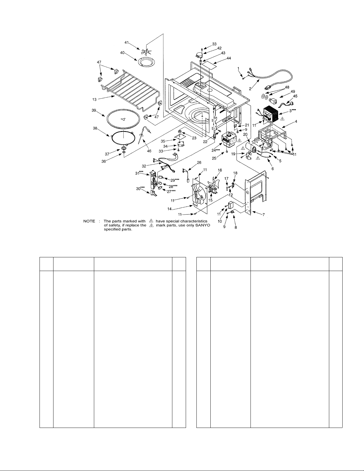
SWITCHES AND MICROWAVE PARTS
*** ALL SERVICE ON MICROWAVE OVENS SHOULD BE PERFORMED BY A QUALIFIED TECHNICIAN USING
APPROVED TESTING EQUIPMENT. CUSTOMERS SHOULD NOT ATTEMPT TO REPLACE PARTS IDENTIFIED
BY A TRIPLE ASTERISK (***).
Key
No.
Part No. Description Q’ty
1 411 160 6106 SCR S-T TRS + SRT 4 x 10 1
2 617 222 2417 Power Cord 1
3 617 222 2530 H.V Transformer,*** YS-S8000 1
4 617 221 9523 Bottom BCT. 1
5 617 124 2300 Lead Wire Assy, H.V. Trans. & Cap. 1
6 617 221 3606 Lead Wire Assy W / Diode 1
7 617 221 9912 Space Partition 1
8 617 222 2509 Thermostat Hood Fan 60oC1
9 411 006 6604 SCR TPG PAN 3 x 6 Z1 3
10 617 222 2523 H.V Capacitor 10uf. 250V 1
11 411 082 5201 SCR TPG TRS 4 x 10 Z1 7
12 411 129 5805 SCR TPG BIN 3 x 10Z1 1
13 617 225 0625 Cook Net 1
14 617 221 7628 Space Partition 1
15 617 197 7417 Motor Complete 1
16 617 196 8507 Blower Fan 1
17 423 021 3704 Fuse, 250V 20A 1
18 617 137 8269 Fuse Holder 1
19 617 077 5830 Capacitor Band 1
20 617 197 6670 H.V. Capacitor, 0.97uf 2.2KV. 1
21 617 124 1235 Thermostat 122oC1
22 411 102 5907 SCR ETG TRS 4 x 10 N2 2
23 617 226 9368 Collar 1
24 415 002 6101 Magnetron 2M219H(B)A*** 1
25 411 160 6106 SCR S-T TRS + SRT 4 x 10 4
26 617 226 2987 Harness, Door Sensing 1
Key
No.
Part No. Description Q’ty
27 617 220 4529 Micro Switch,*** Primary 1
Interlock V-5230Q
28 617 220 4536 Micro Switch,*** Interlock 1
Monitor V-5220Q
29 617 220 4529 Micro Switch,*** Door Sensing 1
V-5230Q
30 617 245 6256 Latch Lever*** 1
31 617 245 6096 Lever Stopper*** 1
32 617 222 0529 Harness, Hood Lamp / TM. 1
33 411 010 5808 SCR EVR PAN 4 x 10 Z1 4
34 617 222 2226 Gear Motor 1
35 617 120 8481 Insulation Sheet 1
36 617 080 5315 Special Washer 1
37 617 220 9401 Turn Table Shaft 1
38 617 204 9489 Roller Base Assy 1
39 617 200 0657 Shelf 1
40 617 222 0550 Cavity Cover 1
41 617 222 2189 Stirrer Fan 1
42 617 222 2202 Gear Motor, Stirrer 1
43 617 222 2196 Stirrer Shaft 1
44 617 222 2172 Lamp Plate 1
45 617 225 0366 Harness, Jack 1
46 617 225 0618 Temp Probe 1
47 617 080 8224 Rod Holder 4
48 617 230 9491 Special Washer, Jack 2
49 617 225 0373 Jack 1
- 4 -
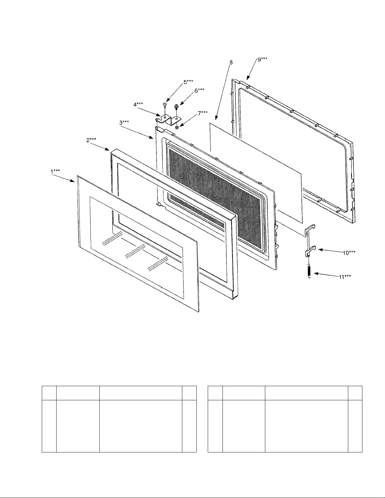
DOOR PARTS
* * * ALL SERVICE ON MICROWAVE OVENS SHOULD BE PERFORMED BY A QUALIFIED TECHNICIAN USING
APPROVED TESTING EQUIPMENT. CUSTOMERS SHOULD NOT ATTEMPT TO REPLACE PARTS IDENTIFIED
BY A TRIPLE ASTERISK (***).
Key
No.
Part No. Description Q’ty
1 617 224 9988 Door Panel*** 1
2 617 224 9964 Door Cover*** 1
3 617 222 2035 Door Main Frame*** (Also 1
order Door Sheet when replacing
Door Main Frame)
4 617 222 1106 Hinge Assy*** 1
5 411 082 5201 SCR TPG TRS 4 x 10 Z1*** 1
Key
No.
Part No
6 411 011 0802 Bolt Hex + SW + W 5 x 14*** 2
7 411 054 1903 Nut Hex + Flg W / SRT 5*** 2
8 617 227 7974 Door Sheet 1
9 617 220 9722 Choke Dielectric*** 1
10 617 179 2478 Door Latch*** 1
11 617 101 1494 Spring*** 1
. Description Q’ty
- 5 -
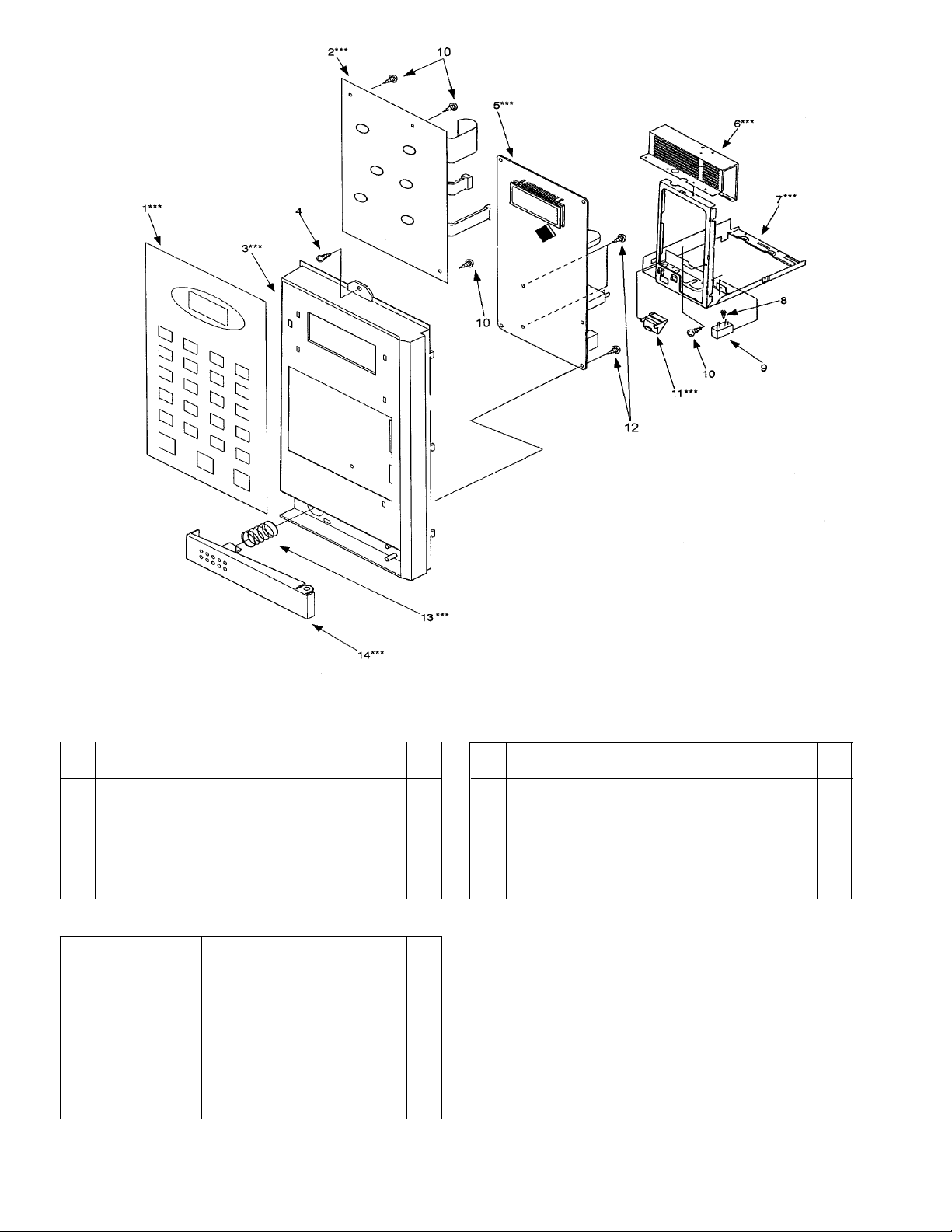
CONTROL PANEL PARTS
* * * ALL SERVICE ON MICROWAVE OVENS SHOULD BE PERFORMED BY A QUALIFIED TECHNICIAN USING
APPROVED TESTING EQUIPMENT. CUSTOMERS SHOULD NOT ATTEMPT TO REPLACE PARTS IDENTIFIED
BY A TRIPLE ASTERISK (***).
Key
No.
Part No. Description Q’ty
1 617 225 0342 Control Sheet*** 1
2 617 224 9667 Power & Control Circuit Board*** 1
3 617 224 8462 Control Frame*** 1
4 411 082 5201 SCR TPG TRS 4 x 10 Z1 1
5 617 224 9650 Power & Control Circuit Board*** 1
6 617 221 9929 Space Partition*** 1
7 617 221 8588 Bottom Plate*** 1
Key
No.
Part No. Description Q’ty
8 411 006 6604 SCR TPG PAN 3 x 6 Z1 1
9 617 200 0381 Thermal Fuse 167oC1
10 411 129 5805 SCR TPG BIN 3 x 10 Z1 21
11 617 222 0567 Latch Lever*** 1
12 411 128 3604 SCR TPG BIN 3 x 12 Z1 2
13 617 080 9559 Spring, Door Release Lever*** 1
14 617 225 0090 Door Release Lever*** 1
PRINTED MATTER (Items Not Illustrated)
Key
No.
Part No. Description Q’ty
617 225 0601 Operating Instruction 1
(English / Spanish)
617 225 0588 Cook Book 1
617 222 2615 Installation Manual 1
(English / Spanish)
617 222 2639 Template 1
617 222 2646 Template 1
617 225 0397 Carton Box Complete 1
617 224 9995 Name Plate 1
- 6 -
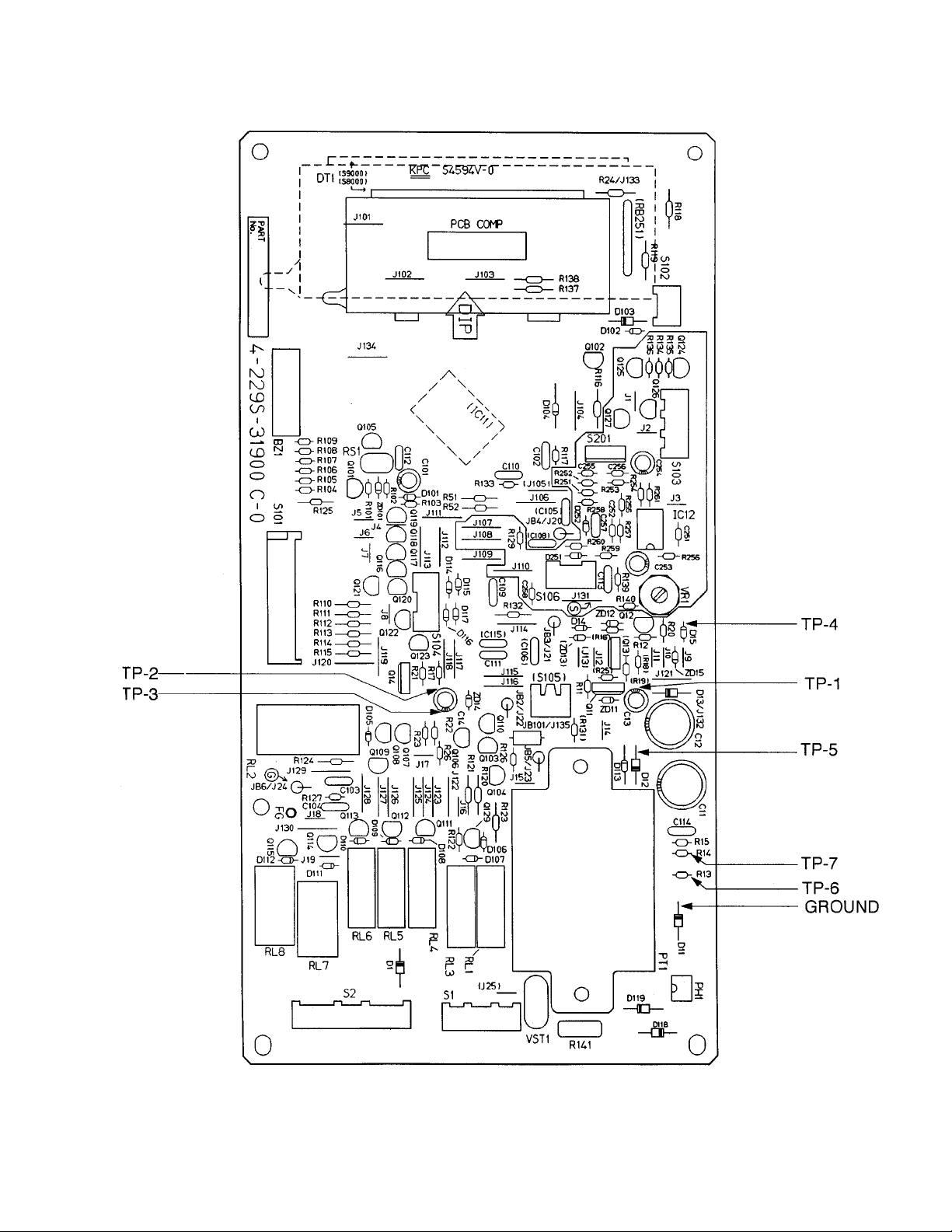
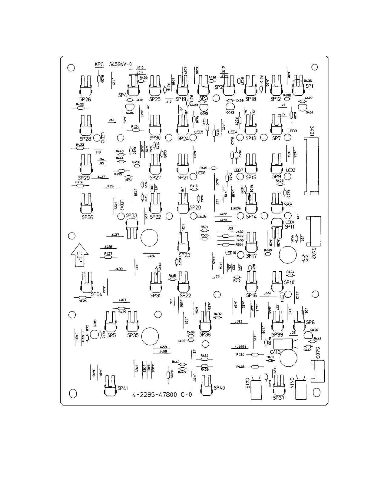
CONTROL CIRCUIT BOARDCONTROL CIRCUIT BOARD
CONTROL CIRCUIT BOARD
CONTROL CIRCUIT BOARDCONTROL CIRCUIT BOARD
(Part No.
617 224 9650617 224 9650
617 224 9650)
617 224 9650617 224 9650
37200
- 7 -
CONTROL CIRCUIT BOARDCONTROL CIRCUIT BOARD
CONTROL CIRCUIT BOARD
CONTROL CIRCUIT BOARDCONTROL CIRCUIT BOARD
(Part No.
Key No. Order Part No. Description Q’ty
INTEGRATED CIRCUIT.
IC11 409 473 8900 IC LM8877-146FP. 1
IC12 409 057 3000 IC UP358C. 1
TRANSISTORS.
Q12,124 405 005 8400 2SA854-Q-T93. 2
Q101, 102 405 082 4609 DTA123YS-TP. 2
Q103 ~ 110 405 072 9904 DTA114ES. 15
116 ~ 119
125 ~ 127
Q129 405 011 8609 2SC1740S-S-TP. 1
Q111 ~ 115 405 141 4106 DTC114YSA-TP. 9
120 ~ 123
Q11, 13, 14 405 125 0902 2SB1238-TV2-Q. 3
DIODES.
D11 ~ 13, 103 407 012 0200 1N4002-TP. 4
D14, 15, 101, 407 012 4406 1SS133-TP. 20
102, 104
105 ~ 117
251, 252
ZD14, 13 407 054 5003 RD13ESB2-TP. 2
ZD11 407 057 0500 RD5.6ESB3. 1
ZD12 407 160 6703 RD27ESB1. 1
ZD15, 101 407 132 2306 HZS3.9ENB2. 2
D1, 118, 119 407 012 0408 1N4004-TP. 3
CAPACITORS.
C258 403 109 3109 Ceramic, 100mfd, 1
C251, 252, 403 166 1209 Ceramic, 1000mfd, 4
255, 256 +-5%, 50V.
C112 403 002 4708 Ceramic, 0.1mfd, 1
C102 ~ 106 403 069 8305 Ceramic, 0.01mfd, 1 1
109 ~ 111 +-5%, 50V.
113, 114, 257
C101 403 147 8807 Electrolytic, 1mfd, 1
C13 403 147 8609 Electrolytic, 47mfd, 1
C253, 254 403 152 7406 Electrolytic, 47mfd, 2
C11, 12 403 045 2907 Electrolytic, 1000mfd, 2
C14 403 147 8708 Electrolytic, 47mfd, 1
RESISTORS.
R141 401 069 8103 Oxide-MT 8.2K 1
R116 401 012 4404 Carbon, 100 ohms 1
R101, 125 401 012 5609 Carbon, 1K ohms 8
104 ~ 109 +-5%, 1/4W.
R15, 16, 102, 401 012 6903 Carbon, 10K ohms 8
122, 127, 129, +-5%, 1/4W.
133, 134
R137, 138 401 012 8006 Carbon, 100K ohms 2
R136 401 013 5202 Carbon, 1.2K ohms 1
R52, 26 401 013 6308 Carbon, 12K ohms 2
R259, 260 401 014 5102 Carbon, 15K ohms 2
R21 ~ 23 401 015 0403 Carbon, 18 ohms 3
R13, 14 401 016 2505 Carbon, 220 ohms 2
R11, 139 401 016 3700 Carbon, 2.2K ohms 2
617 224 9650617 224 9650
617 224 9650)
617 224 9650617 224 9650
+-5%, 50V.
+-5%, 25V.
+-20%, 50V.
+-20%, 10V.
+-20%, 16V.
+-20%, 25V.
+-20%, 25V.
+-5%, 2W.
+-5%, 1/4W.
+-5%, 1/4W.
+-5%, 1/4W.
+-5%, 1/4W.
+-5%, 1/4W.
+-5%, 1/4W.
+-5%, 1/4W.
+-5%, 1/4W.
Key No. Order Part No. Description Q’ty
RESISTORS.
R140 401 016 9603 Carbon, 27 ohms 1
R132 401 017 1705 Carbon, 2.7K ohms 1
R123 401 018 2701 Carbon, 330 ohms 1
R124 401 018 3708 Carbon, 3.3K ohms 1
R118, 119 401 018 9700 Carbon, 39 ohms 2
R120, 135 401 019 0904 Carbon, 390 ohms 2
R17, 121 401 020 1907 Carbon, 4.7K ohms 8
110 ~ 115 +-5%, 1/4W.
R103, 126 401 020 2805 Carbon, 47K ohms 2
R12, 20 401 021 2903 Carbon, 5.6K ohms 2
R18, 19, 401 023 0600 Carbon, 82 ohms 5
253, 254, 261 +-5%, 1/4W.
R117 401 023 1607 Carbon, 820 ohms 1
R252 401 103 3309 MT-Film, 1.47K ohms 1
R251 401 112 4106 MT-Film, 1.54K ohms 1
R131 401 100 8000 MT-Film, 18K ohms 1
R255, 256 401 155 7706 MT-Film, 2.05K ohms 2
R257, 258 401 155 7805 MT-Film, 820K ohms 2
RESISTORS BLOCK.
RB251 617 122 9066 Resistor Network. 1
MISCELLANEOUS.
BZ1 420 000 6800 Buzzer, PKM22EPT. 1
VST1 407 118 5505 Varistor ENC 471D-10A. 1
VR1 617 148 4717 Variable Resistor. 1
DT1 617 196 7678 Display Tube. 1
RL1, 3 ~ 6 617 201 3978 Relay, G5N-1A-DC12. 5
RL2 617 141 0549 Relay, DU12D1-1PR. 1
RL7, 8 617 196 7869 Relay, AJQ1341. 2
RS1 617 128 3372 Ceramic Oscillator. 1
S 1 617 201 3985 Connector. 1
S 2 617 220 2525 Connector. 1
S101 617 226 6749 Connector. 1
S102 617 226 6510 Connector. 1
S103 617 230 6667 Connector. 1
S104 617 225 3657 Connector. 1
S105 617 230 7121 Connector. 1
S106 617 227 8094 Connector. 1
S201 617 002 4396 Connector. 1
PT 1 617 222 7344 Step-Down Transformer, 1
FG 617 226 7425 Lead Wire. 1
PH1 407 200 4904 PH / Couple PC817X3. 1
2 617 226 6671 Spacer. 1
JB101 617 144 9259 Noise Filter. 1
JB2 ~ 6 617 132 5744 Noise Filter. 5
J1 ~ 12, 617 079 4299 Jumper. 1 8
J14 ~ 19
J101 ~ 131, 617 079 4237 Jumper. 3 3
133, 134
+-5%, 1/4W.
+-5%, 1/4W.
+-5%, 1/4W.
+-5%, 1/4W.
+-5%, 1/4W.
+-5%, 1/4W.
+-5%, 1/4W.
+-5%, 1/4W.
+-5%, 1/4W.
+-1%, 1/6W.
+-1%, 1/6W.
+-1%, 1/6W.
+-1%, 1/6W.
+-1%, 1/6W.
P6TK-S8000.
- 8 -
CONTROL CIRCUIT BOARDCONTROL CIRCUIT BOARD
CONTROL CIRCUIT BOARD
CONTROL CIRCUIT BOARDCONTROL CIRCUIT BOARD
(Part No.
617 224 9667617 224 9667
617 224 9667)
617 224 9667617 224 9667
- 9 -
CONTROL CIRCUIT BOARDCONTROL CIRCUIT BOARD
CONTROL CIRCUIT BOARD
CONTROL CIRCUIT BOARDCONTROL CIRCUIT BOARD
(Part No.
617 224 9667617 224 9667
617 224 9667)
617 224 9667617 224 9667
Key No. Order Part No. Description Q’ty
INTEGRATED CIRCUIT.
IC401, 409 057 2706 IC UPC339G2. 10
404 ~ 412
IC402 409 057 3604 IC UPC393G2. 1
TRANSISTORS.
Q401 ~ 406 405 072 9904 DTA114ES. 6
DIODES.
D401 407 012 4406 1SS133-TP. 1
Key No. Order Part No. Description Q’ty
RESISTORS.
R449 ~ 454 401 012 4404 Carbon, 100 ohms 6
+-5%, 1/4W.
R401 ~ 435 401 012 8006 Carbon, 100K ohms 3 5
+-5%, 1/4W.
R455 401 013 6308 Carbon, 12K ohms 1
+-5%, 1/4W.
R501 ~ 506 401 015 2605 Carbon, 1.8K ohms 6
+-5%, 1/4W.
R448 401 020 1907 Carbon, 4.7K ohms 1
+-5%, 1/4W.
R456 401 020 2805 Carbon, 47K ohms 1
+-5%, 1/4W.
R442 ~ 447 401 021 4907 Carbon, 560K ohms 6
+-5%, 1/4W.
R436 ~ 441 401 022 4005 Carbon, 68K ohms 6
+-5%, 1/4W.
CAPACITORS.
C401 ~ 412 403 109 3109 Ceramic, 100PK, 1
+-5%, 50V.
C414 403 152 8106 Electrolytic, 47mfd, 1
+-20%, 50V.
C413, 415 403 147 8609 Electrolytic, 47mfd, 2
+-20%, 10V.
MISCELLANEOUS.
S402 617 227 2849 Connector. 1
S402 617 227 2061 Housing Assy. 1
S403 617 227 5093 Connector. 1
S403 617 227 2054 Housing Assy. 1
S401 617 226 6749 Connector. 1
S401 617 228 6075 Flat Cable. 1
LED1 ~ 13 407 201 3708 LED, SEL6914A-TP5. 1 3
SP1 ~ 41 617 226 9498 Spring. 41
J1 ~ 31 617 079 4299 Jumper. 3 1
J401 ~ 469 617 079 4237 Jumper. 6 9
- 10 -
 Loading...