

Sanyo EM-F3400SW User Manual
File No :File No :
File No :
File No :File No :
SER SER
SER
SER SER
VICE MANUALVICE MANUAL
VICE MANUAL
VICE MANUALVICE MANUAL
Micr Micr
Micr
Micr Micr
owave Ovenowave Oven
owave Oven
owave Ovenowave Oven
Pr Pr
oduct Code No.oduct Code No.
Pr
oduct Code No.
Pr Pr
oduct Code No.oduct Code No.
EM-F3400SW EM-F3400SW
EM-F3400SW
EM-F3400SW EM-F3400SW
437 450 57437 450 57
437 450 57
437 450 57437 450 57
(U.S.A.)(U.S.A.)
(U.S.A.)
(U.S.A.)(U.S.A.)
CAUTIONCAUTION
CAUTION
CAUTIONCAUTION
WW
ARNING TO SERARNING TO SER
W
ARNING TO SER
WW
ARNING TO SERARNING TO SER
VICE TECHNICIANSVICE TECHNICIANS
VICE TECHNICIANS
VICE TECHNICIANSVICE TECHNICIANS
PRECAUTIONS TO BE OBSERVED BEFORE AND DURING
SERVICING TO AVOID POSSIBLE EXPOSURE TO
EXCESSIVE MICROWAVE ENERGY
(a) Do not operate or allow the oven to be operated with the door open.
(b) Make the following safety checks on all ovens to be serviced before activating the magnetron or other
microwave source, and make repairs as necessary :
(1) Interlock operation, (2) proper door closing, (3) seal and sealing surfaces (arcing, wear, and other damage),
(4) damage to or loosening of hinges and latches, (5) evidence of dropping or abuse.
(c) Before turning on microwave power for any service test or inspection within the microwave generating
compartments, check the magnetron, wave guide or transmission line, and cavity for proper alignment, integrity,
and connections.
(d) Any defective or misadjusted components in the interlock, monitor, door seal, and microwave generation and
transmission systems shall be repaired, replaced, or adjusted by procedures described in this manual before
the oven is released to the owner.
(e) A microwave leakage check to verify compliance with the Federal per formance standard should be performed
on each oven prior to release to the owner.
REFERENCE NO. SM-860304
CAUTIONCAUTION
CAUTION
CAUTIONCAUTION
For micrFor micr
For micr
For micrFor micr
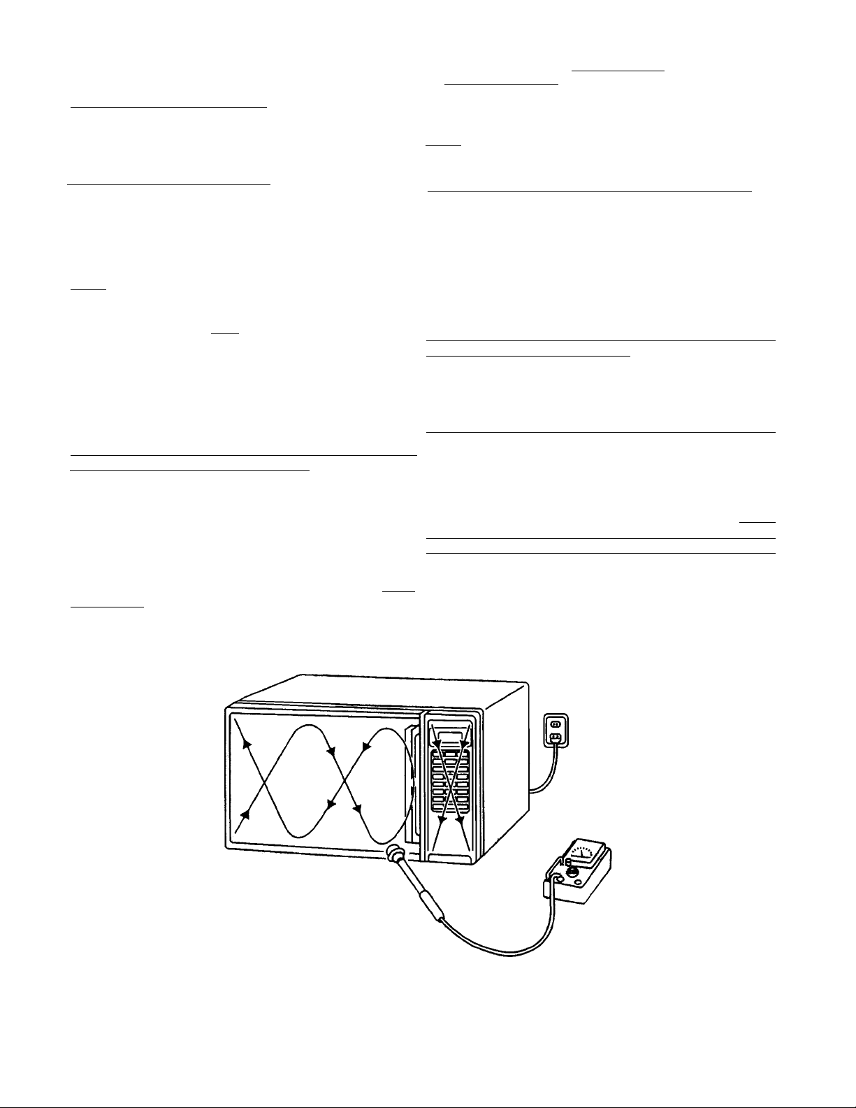
On every service calls, check for microwave energy
emission, must be made according to the following manner.
MeasurMeasur
Measur
MeasurMeasur
Measurement must be made with the microwave oven
operating at its maximum output and containing a load of
275±15 milliliters of tap water initially at 20
±9oF) placed within the cavity at the center.
NOTENOTE
NOTE : The water container must be a 600 milliliter beaker
NOTENOTE
A properly operating door and seal assembly will normally
register emission on greater than 4mW/cm2 to allow for
measurement uncertainty with the cooking shelf or tray in
place.
All repairs must be performed in such a manner All repairs must be performed in such a manner
All repairs must be performed in such a manner
All repairs must be performed in such a manner All repairs must be performed in such a manner
micrmicr
micr
micrmicr
Follow the instructions supplied with a detector being used
and performed an R.F. emission test around the door front
and edges and all edges and vent of the outer case. The
cabinet (wrapper) must be in place and the oven fully
assembled.
When performing emission survey, with the meter on FAST
RESPONSE the movement of a detector probe shall not
exceed one (1) inch per second.
owave enerowave ener
owave ener
owave enerowave ener
ement of enerement of ener
ement of ener
ement of enerement of ener
and made of an electrically none conductive
material such as glass or plastic.
The cook tray must be in place when measuring
emission.
owave enerowave ener
owave ener
owave enerowave ener
gy emissiongy emission
gy emission
gy emissiongy emission
gy emissiongy emission
gy emission
gy emissiongy emission
gy emission argy emission ar
gy emission ar
gy emission argy emission ar
e minimal.e minimal.
e minimal.
e minimal.e minimal.
o±5o
celsius (68
thatthat
that
thatthat
In the area emitting the highest reading, switch the meter
to SLOW RESPONSE, and take a reading for minimum of
three (3) seconds. We recommended the pattern outline
shown below when the door surface is surveyed.
NOTENOTE
NOTE : Periodically check to be sure that the probe tip is
NOTENOTE
not worn or dirty.
The following U.S. standard applies to microwave ovens :
21 CFR 1030.10, Performance Standard for Microwave
Ovens.
It requires that the power density of the microwave
radiation emitted by a microwave oven shall not exceed
five (5) milliwatts per square centimeter at any point 5
centimeter (about 2 inches) or more from the external
surface of the oven.
All microwave ovens exceeding the emission level of
4mW/cm
microwave ovens and the manufacturer immediately and
the owner should be told not to use the microwave oven
until it has been repaired completely.
If a microwave oven is found to operate with the door open,
report to Dept. of Service, the manufacturer and CDRH*
immediately. Also tell the owner not to use the oven.
*CDRH : Center for Device and Radiological Health.
The interlock monitor switch acts as the final safety switch
protecting the customer from microwave radiation. If the
interlock monitor switch operates to blow the fuse with
interlocks failed, you must replace all interlock switches
primary and secondary interlock switches and the monitor
switch with new ones because the contacts of those
interlock switches may be melted and welded together.
2
must be reported to Dept. of Service for
- i -
- TABLE OF CONTENTS -
Adjustment Procedures ................................................... 1
Specifications .................................................................. 2
Power Output Measurement ........................................... 2
Precautions and Repair Service Tips .............................. 2
Circuit Diagram ............................................................... 3
1.1.
ADJUSTMENT PROCEDURESADJUSTMENT PROCEDURES
1.
ADJUSTMENT PROCEDURES
1.1.
ADJUSTMENT PROCEDURESADJUSTMENT PROCEDURES
TT
O AO A
VOID POSSIBLE EXPOSURE TO MICROWVOID POSSIBLE EXPOSURE TO MICROW
T
O A
VOID POSSIBLE EXPOSURE TO MICROW
TT
O AO A
VOID POSSIBLE EXPOSURE TO MICROWVOID POSSIBLE EXPOSURE TO MICROW
ENERGY LEAKAGE, THE FOLLOWINGENERGY LEAKAGE, THE FOLLOWING
ENERGY LEAKAGE, THE FOLLOWING
ENERGY LEAKAGE, THE FOLLOWINGENERGY LEAKAGE, THE FOLLOWING
ADJUSTMENT OF THE INTERLOCK SWITCHESADJUSTMENT OF THE INTERLOCK SWITCHES
ADJUSTMENT OF THE INTERLOCK SWITCHES
ADJUSTMENT OF THE INTERLOCK SWITCHESADJUSTMENT OF THE INTERLOCK SWITCHES
SHOULD BE MADE ONLSHOULD BE MADE ONL
SHOULD BE MADE ONL
SHOULD BE MADE ONLSHOULD BE MADE ONL
SERSER
VICE PERSONNEL.VICE PERSONNEL.
SER
VICE PERSONNEL.
SERSER
VICE PERSONNEL.VICE PERSONNEL.
The SANYO service center should have the designated
detector to measure the microwave energy leakage
after the repair or adjustment.
NOTENOTE
NOTE : Detector to be used at the service center is
NOTENOTE
NARDA 8100, 8200 or the equivalent.
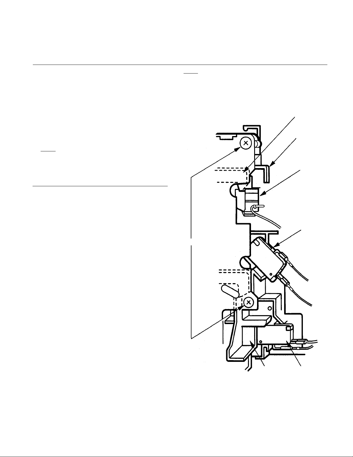
PRIMARPRIMAR
PRIMAR
PRIMARPRIMAR
MONITOR SWITCH AND DOOR SENSING SWITCHMONITOR SWITCH AND DOOR SENSING SWITCH
MONITOR SWITCH AND DOOR SENSING SWITCH
MONITOR SWITCH AND DOOR SENSING SWITCHMONITOR SWITCH AND DOOR SENSING SWITCH
ADJUSTMENTADJUSTMENT
ADJUSTMENT
ADJUSTMENTADJUSTMENT
(Figure 1)(Figure 1)
(Figure 1)
(Figure 1)(Figure 1)
Y INTERLOCK SWITCH, INTERLOCKY INTERLOCK SWITCH, INTERLOCK
Y INTERLOCK SWITCH, INTERLOCK
Y INTERLOCK SWITCH, INTERLOCKY INTERLOCK SWITCH, INTERLOCK
Y BY AUTHORIZEDY BY AUTHORIZED
Y BY AUTHORIZED
Y BY AUTHORIZEDY BY AUTHORIZED
AA
VEVE
A
VE
AA
VEVE
Test Procedures and Troubleshooting .................... 4 ~ 10
Disassembly Instructions ....................................... 11 ~ 14
Exploded View and Parts List ................................ 15 ~ 20
Overall Circuit Diagram .......................................... 21
NOTENOTE
NOTE : If the interlock monitor circuit operates and at the
NOTENOTE
same time the fuse blows with the door opened,
be sure to replace the control circuit board because
relay 2 on the control circuit board, the door sensing
switch and the electric circuit related on the
door sensing switch, which act as Secondary
Interlock Switch.
Door
Latch
Lever Stopper
Door
Sensing
Switch
(1) Loosen 2 screws securing the lever stopper.
(2) Adjust the lever stopper position so that it is pushed
forward and pull backward until there is about zero
gap between the latch lever and switch body on the
primary interlock switch and at the same time there
is about zero gap between the door latch and the
switch body on the door sensing switch when the
door latch is securely locked.
(3) Tighten the lever stopper screws securely.
(4) Make sure the interlock monitor switch closes after
the primary interlock switch opens when the door
is opened very slowly, according to “CHECKOUT
PROCEDURE FOR SWITCHES” on page 6.
(5) Make sure the interlock monitor switch opens before
the primary interlock switch closes when the door is
closed very slowly, according to “CHECKOUT
PROCEDURE FOR SWITCHES” on page 6.
(6) Make sure the microwave energy leakage should be
no greater than 4mW/cm2 to allow for measurement
uncertainty when measured with a detector.
(All service adjustments must be made for
minimum microwave energy leakage readings.)
Interlock
Monitor
Switch
Screws
- 1 -
Figure 1Figure 1
Figure 1
Figure 1Figure 1
Latch
Lever
Primary
Interlock
Switch

2.2.
SPECIFICASPECIFICA
2.
SPECIFICA
2.2.
SPECIFICASPECIFICA
Rated Power Consumption .. 1480W.
Microwave Output ................ 1050W.
Frequency ............................. 2,450MHz±50MHz.
Power Supply ........................120V±12V, 60Hz.
Rated Current ....................... 12.9 Amp.
Safety Devices ..................... Thermal Fuse open at
Timer .....................................Electronic Digital, up to
Overall Dimensions ................ 205/8”(W) x 161/2”(D) x 113/8”(H)
Oven Cavity Size .................. 133/4”(W) x 145/8”(D) x 81/2”(H)
Turn Table Diameter ..............107/8”
Effective Capacity of
Oven Cavity .......................... 1.1 Cubic Feet.
Net Weight ........................... Approx. 34.5 Lbs.
3.3.
POWER OUTPUT MEASUREMENTPOWER OUTPUT MEASUREMENT
3.
POWER OUTPUT MEASUREMENT
3.3.
POWER OUTPUT MEASUREMENTPOWER OUTPUT MEASUREMENT
NOTENOTE
NOTE
NOTENOTE
The power output specification, 1050W. on this model is
measured with IEC measurement. The power output is
measured with two (2) liters water is equivalent to 1050W.
in measurement with IEC, when measured with the following
power output.
(1) Fill two beakers (glass or plastic) with each one liter of
tap water (about 20°C) and measure the water temperature.
(Use a thermometer with a 1/10 degree gauge).
(2) Place the beakers side by side in the center of the glass tray.
(3) Close the door, set the “TIME” for two minutes. (“200” in
the display window). Touch the “START” key and heat
the water exactly for two minutes.
(4) Take the beakers out, immediately stir the water and
measure the water temperature respectively.
(5) Calculate the temperature rise of water in each beaker.
Then calculate the average value of two temperature rises.
Output power can be calculated by the equation :
Power Output (W) = 70 x ∆t
Where ∆t is an average temperature rise in degrees
Centigrade.
(6) Power Output shall be in the following range :
Minimum 19.6°F (10.9°C) 763W
Maximum 20.0°F (14.0°C) 980W
(7) Power Output is affected by the line voltage under load.
For correct Power Output measurement, the line voltage
under load must be 120±1 volts.
TIONSTIONS
TIONS
TIONSTIONS
332°F (167°C) for Cavity.
Thermal Protector open at
252°F (122°C) for Magnetron.
Fuse (Cartridge Type 20A)
Primary Interlock Switch,
Door Sensing Switch and
Relay 2.
Interlock Monitor Switch.
99 min. 99 sec.
Average Temperature Rise Power Output
4.4.
PRECAUTIONS AND REPPRECAUTIONS AND REP
4.
PRECAUTIONS AND REP
4.4.
PRECAUTIONS AND REPPRECAUTIONS AND REP
PRELIMINARPRELIMINAR
PRELIMINAR
PRELIMINARPRELIMINAR
A.A.
SINCE NEARLSINCE NEARL
A.
SINCE NEARL
A.A.
SINCE NEARLSINCE NEARL
CUITS OF THIS MICROWCUITS OF THIS MICROW
CUITS OF THIS MICROW
CUITS OF THIS MICROWCUITS OF THIS MICROW
BE CARRIED OUT WITH GREABE CARRIED OUT WITH GREA
BE CARRIED OUT WITH GREA
BE CARRIED OUT WITH GREABE CARRIED OUT WITH GREA
B.B.
TO ATO A
B.
TO A
B.B.
TO ATO A
ENERGY LEAKAGE, THE FOLLOWING PRECAUTIONSENERGY LEAKAGE, THE FOLLOWING PRECAUTIONS
ENERGY LEAKAGE, THE FOLLOWING PRECAUTIONS
ENERGY LEAKAGE, THE FOLLOWING PRECAUTIONSENERGY LEAKAGE, THE FOLLOWING PRECAUTIONS
MUST BE TMUST BE T
MUST BE T
MUST BE TMUST BE T
(1) Before the power is applied :
(a) Open and close door several times to make sure the
(b) Make sure the perforated screen and the choke die-
(2) After the power is applied :
(a) Open and close the door to see if the interlock mech-
(b) Check microwave energy leakage with a leakage
(3) Do not operate the unit until it is completely repaired,
if any of the following conditions exists :
(a) Door does not close firmly against the cavity front.
(b) The hinge is broken.
(c) The choke dielectric or the door seal is damaged.
(d) The door is bent or warped, or there is any other
NOTE :
(e) Make sure that there are no defective parts in the
(f) Make sure there are no defective parts in the
(4) The following items should be checked after the unit
is repaired :
(a) The interlock monitor switch is connected correctly
(b) The magnetron gasket on the magnetron is properly
(c) Waveguide and oven cavity are intact (no leakage of
(d) The door can be properly closed and the safety
(e) The oven must be stopped when the door is opened
The oven must not be operated with any of the aboveThe oven must not be operated with any of the above
The oven must not be operated with any of the above
The oven must not be operated with any of the aboveThe oven must not be operated with any of the above
components rcomponents r
components r
components rcomponents r
YY
Y
YY
Y 2,000 VOLY 2,000 VOL
Y 2,000 VOL
Y 2,000 VOLY 2,000 VOL
VOID POSSIBLE EXPOSURE TO MICROWVOID POSSIBLE EXPOSURE TO MICROW
VOID POSSIBLE EXPOSURE TO MICROW
VOID POSSIBLE EXPOSURE TO MICROWVOID POSSIBLE EXPOSURE TO MICROW
AKEN BEFORE SERAKEN BEFORE SER
AKEN BEFORE SER
AKEN BEFORE SERAKEN BEFORE SER
primary interlock switch, the interlock monitor switch
and the door sensing switch operate properly.
(Listen for the clicking sound from the switches).
Make sure the interlock monitor switch closes after
the primary interlock switch is opens when the door
is opened. (See pages 1 and 6).
lectric of the door are correctly mounted.
anism operates properly.
detector and confirm the energy leakage should be
no greater than 4mW/cm
uncertainty.
visible damage to the oven that may cause microwave
energy leakage.
Always keep the seal clean.Always keep the seal clean.
Always keep the seal clean.
Always keep the seal clean.Always keep the seal clean.
interlock mechanism.
microwave generating and transmission assembly.
(especially waveguide).
and firmly.
positioned.
microwave energy).
switches work properly.
or the time is up.
emoved or bypassed.emoved or bypassed.
emoved or bypassed.
emoved or bypassed.emoved or bypassed.
AIR SERAIR SER
AIR SER
AIR SERAIR SER
TS EXISTS IN SOME CIR-TS EXISTS IN SOME CIR-
TS EXISTS IN SOME CIR-
TS EXISTS IN SOME CIR-TS EXISTS IN SOME CIR-
AA
VE OVEN, REPVE OVEN, REP
A
VE OVEN, REP
AA
VE OVEN, REPVE OVEN, REP
T CARE.T CARE.
T CARE.
T CARE.T CARE.
VICING.VICING.
VICING.
VICING.VICING.
2
to allow for measurement
VICE TIPSVICE TIPS
VICE TIPS
VICE TIPSVICE TIPS
AIRS SHOULDAIRS SHOULD
AIRS SHOULD
AIRS SHOULDAIRS SHOULD
AA
VEVE
A
VE
AA
VEVE
- 2 -
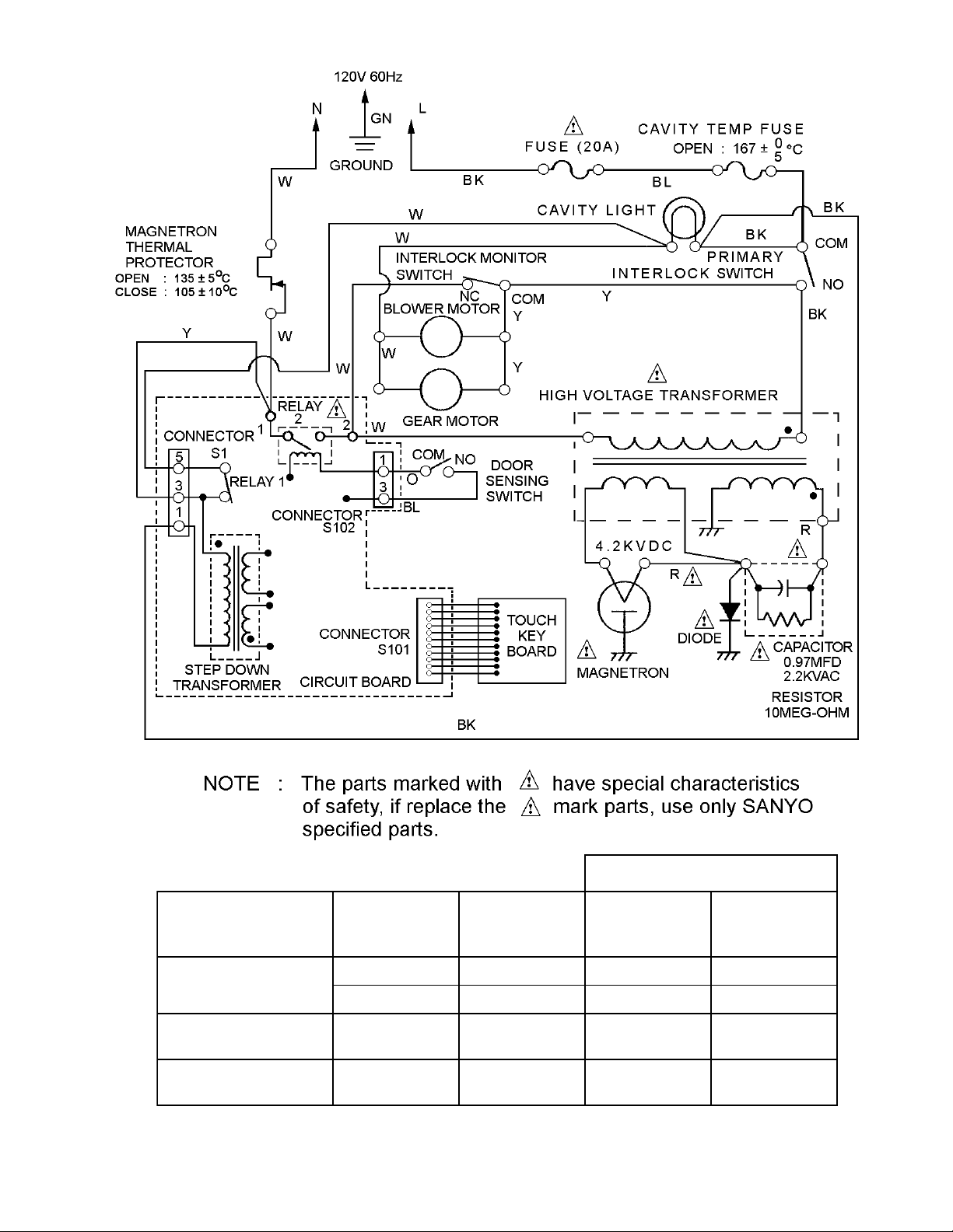
5. CIRCUIT DIAGRAM
DNOCTINOI
Figure 2Figure 2
Figure 2
Figure 2Figure 2
KCOLRETNIYRADNOCES
YRAMIRP
EDAMHCTIWS
•
NEPOROOD
ESOLCROOD
•••
KCOLRETNI
HCTIWS
MOCMOCMOCMOC
ONCNONON
•
- 3 -
KCOLRETNI
ROTINOM
HCTIWS
ROOD
GNISNES
HCTIWS
2YALER
6. TEST PROCEDURES AND TROUBLESHOOTING6. TEST PROCEDURES AND TROUBLESHOOTING
6. TEST PROCEDURES AND TROUBLESHOOTING
6. TEST PROCEDURES AND TROUBLESHOOTING6. TEST PROCEDURES AND TROUBLESHOOTING
CAUTIONCAUTION
CAUTION
CAUTIONCAUTION
- DISCONNECT THE POWER SUPPL- DISCONNECT THE POWER SUPPL
- DISCONNECT THE POWER SUPPL
- DISCONNECT THE POWER SUPPL- DISCONNECT THE POWER SUPPL
THE WTHE W
ALL OUTLET WHENEVER REMOVING THEALL OUTLET WHENEVER REMOVING THE
THE W
ALL OUTLET WHENEVER REMOVING THE
THE WTHE W
ALL OUTLET WHENEVER REMOVING THEALL OUTLET WHENEVER REMOVING THE
CABINET FROM THE UNITCABINET FROM THE UNIT
CABINET FROM THE UNIT
CABINET FROM THE UNITCABINET FROM THE UNIT
TESTS ONLTESTS ONL
TESTS ONL
TESTS ONLTESTS ONL
VOLVOL
TT
VOL
T
VOLVOL
TT
WIRES FROM THE PRIMARWIRES FROM THE PRIMAR
WIRES FROM THE PRIMAR
WIRES FROM THE PRIMARWIRES FROM THE PRIMAR
HIGH VOLHIGH VOL
HIGH VOL
HIGH VOLHIGH VOL
A.A.
TEST PROCEDURESTEST PROCEDURES
A.
TEST PROCEDURES
A.A.
TEST PROCEDURESTEST PROCEDURES
Y AFTER DISCHARGING THE HIGHY AFTER DISCHARGING THE HIGH
Y AFTER DISCHARGING THE HIGH
Y AFTER DISCHARGING THE HIGHY AFTER DISCHARGING THE HIGH
AGE CAPAGE CAP
AGE CAP
AGE CAPAGE CAP
ACITOR AND REMOVING THE LEADACITOR AND REMOVING THE LEAD
ACITOR AND REMOVING THE LEAD
ACITOR AND REMOVING THE LEADACITOR AND REMOVING THE LEAD
TT
AGE TRANSFORMER. (SEE FIGURE 3)AGE TRANSFORMER. (SEE FIGURE 3)
T
AGE TRANSFORMER. (SEE FIGURE 3)
TT
AGE TRANSFORMER. (SEE FIGURE 3)AGE TRANSFORMER. (SEE FIGURE 3)
Y CORD FROMY CORD FROM
Y CORD FROM
Y CORD FROMY CORD FROM
, PROCEED WITH THE, PROCEED WITH THE
, PROCEED WITH THE
, PROCEED WITH THE, PROCEED WITH THE
Y WINDING OF THEY WINDING OF THE
Y WINDING OF THE
Y WINDING OF THEY WINDING OF THE
Secondary
Windings
Filament Windings
Primary
Windings
Figure 3Figure 3
Figure 3
Figure 3Figure 3
COMPONENT COMPONENT
COMPONENT
COMPONENT COMPONENT
MAGNETRON
CHECKOUT PROCEDURE CHECKOUT PROCEDURE
CHECKOUT PROCEDURE
CHECKOUT PROCEDURE CHECKOUT PROCEDURE
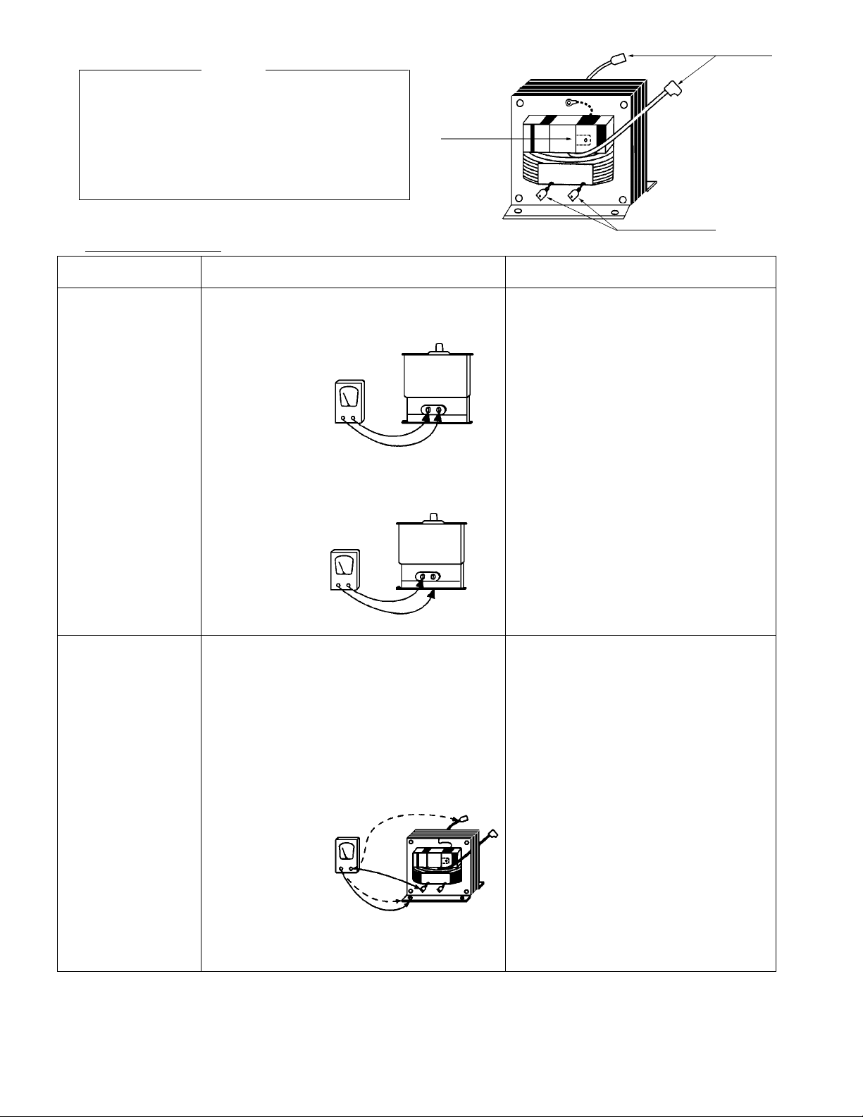
1) Check for resistance : Across the filament Normal reading :
terminals of the Magnetron with an Ohm-Meter Less than 1 Ohm.
on R x 1 scale.
Ohm-MeterOhm-Meter
Ohm-Meter
Ohm-MeterOhm-Meter
Figure 4Figure 4
Figure 4
Figure 4Figure 4
2) Check for resistance : Between each filament Normal reading :
terminal of the Magnetron and the chassis Infinite Ohms.
ground with an Ohm-Meter on highest scale.
Ohm-MeterOhm-Meter
Ohm-Meter
Ohm-MeterOhm-Meter
Figure 5Figure 5
Figure 5
Figure 5Figure 5
1) Measure the resistance : Normal readings :
With an Ohm-Meter on R x 1 scale.
a. Primary winding : Approximately 0.38 Ohms.
b. Filament winding : Less than 1 Ohm.
c. Secondary winding : Approximately 82.0 Ohms.
RESUL RESUL
RESUL
RESUL RESUL
TT
T
TT
HIGH-VOLTAGE
TRANSFORMER
2) Measure the resistance : Normal readings :
With an Ohm-Meter on highest scale.
a. Primary winding to ground. Infinite Ohms.
b Filament winding to ground. Infinite Ohms.
Ohm-MeterOhm-Meter
Ohm-Meter
Ohm-MeterOhm-Meter
Figure 6Figure 6
Figure 6
Figure 6Figure 6
Note Note
Note : Remove varnish of
Note Note
measured point.
- 4 -
COMPONENT COMPONENT
COMPONENT
COMPONENT COMPONENT
HIGH-VOLTAGE
CAPACITOR
including
BLEEDER
RESISTOR
CHECKOUT PROCEDURE CHECKOUT PROCEDURE
CHECKOUT PROCEDURE
CHECKOUT PROCEDURE CHECKOUT PROCEDURE
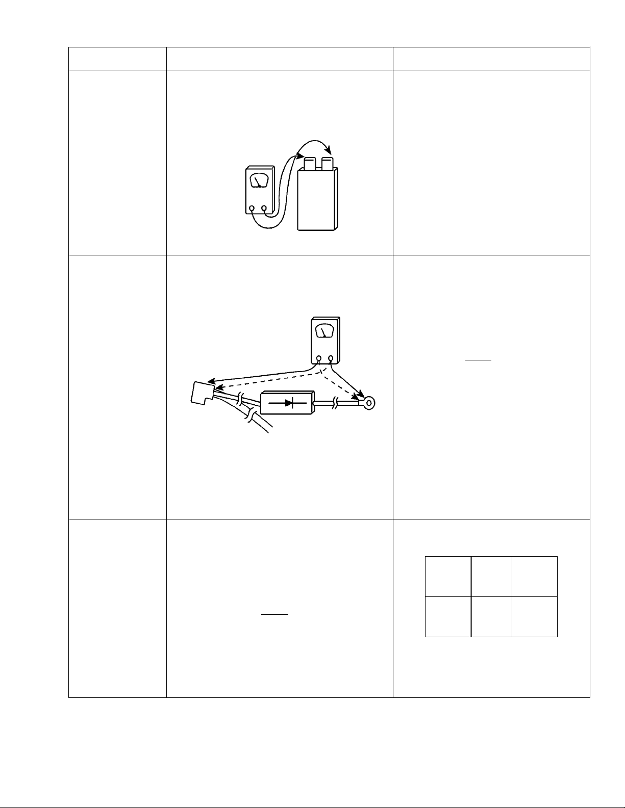
Measure the resistance : Across two terminals Normal reading :
with an Ohm-Meter on highest scale. Momentarily indicates several Ohms,
Abnormal reading :
Ohm-MeterOhm-Meter
Ohm-Meter
Ohm-MeterOhm-Meter
Figure 7Figure 7
Figure 7
Figure 7Figure 7
Measure the resistance : Across two terminals Normal reading :
with an Ohm-Meter on R x 10,000 scale. Indicates about the middle position in
Ohm-MeterOhm-Meter
Ohm-Meter
Ohm-MeterOhm-Meter
RESUL RESUL
RESUL
RESUL RESUL
and gradually returns to 10 Meg-Ohms.
Indicates continuity or 10 Meg-Ohms
from the beginning.
one direction (forward direction) and
infinite ohms in the reverse direction,
using meter which is provided with a
9 volt battery.
TT
T
TT
HIGH-VOLTAGE
DIODE
CONTROL
CIRCUIT
BOARD
Figure 8Figure 8
Figure 8
Figure 8Figure 8
Measure the voltage : Between test point TP-1,
TP-2 and Ground. (See Control Circuit Board on
page 19).
- Proceed with the check of the Step-Down
Transformer, to see if any one of the measured
values is different from the specified values.
NOTENOTE
NOTE
NOTENOTE
NOTENOTE
NOTE
NOTENOTE
- Some digital meter may show over
even in a forward direction because
low measuring voltage of meter does
not allow the meter current to pass
through the High Voltage Diode.
Abnormal reading :
Indicates continuity or infinite Ohms
in both directions.
Test
Point
Voltage
TP-1 TP-2
-5V -15V
DC DC
- 5 -
 Loading...