Sanyo EM-D953 Service Manual


FILE No.


SERVICE MANUAL

MICROWAVE OVEN WITH

EM-D953(UK WHITE)


CONVECTION AND GRILL

EM-D953(UK GREEN)


EM-D953(UK BROWN)

Auto Def. Grill

Convec.

Time

Start


Kg


LB


OZ

80 150

300

450

750 900


D I R E C T

AC C E S S


Baked


Chicken

Frozen

Potato


Pieces


Pizza

Roast

Casserole


Cake/

Joint


Pudding

Baked


Chops/


Fish


Snacks


Steaks


Slow Cook

Auto Defrost


Low / High

More / Less

Micro


Power Convec.


Grill


Temp.

1.

+ Micro


2. Convec.


3. Convec.

+ Grill


Dual Cook

Micro + Grill


Up


Clear/Stop

TIMER / WEIGHT


C


Down


Start


EM-D953

Auto Def. Grill

Convec. Time Start


Kg


LB


OZ

80 150

300

450

750 900

D I R E C T AC C E S S

Baked

Chicken


Frozen

Pieces


Pizza

Potato


Roast

Casserole

Cake/

Pudding

Joint


Baked

Chops/


Snacks

Fish


Steaks


Slow Cook

Auto Defrost

More / Less

Low / High


Micro Power Convec.Temp.

Grill

1. Convec. + Micro

Dual Cook

2. Convec. + Grill


3. Micro + Grill


Clear/Stop

Up


C

TIMER / WEIGHT

Down

Start


EM-D953

Product Code No.

EM-D953(UK White)

43736813

EM-D953(UKGreen)

43736815

EM-D953(UK Brown)

43736814


FOREWORD

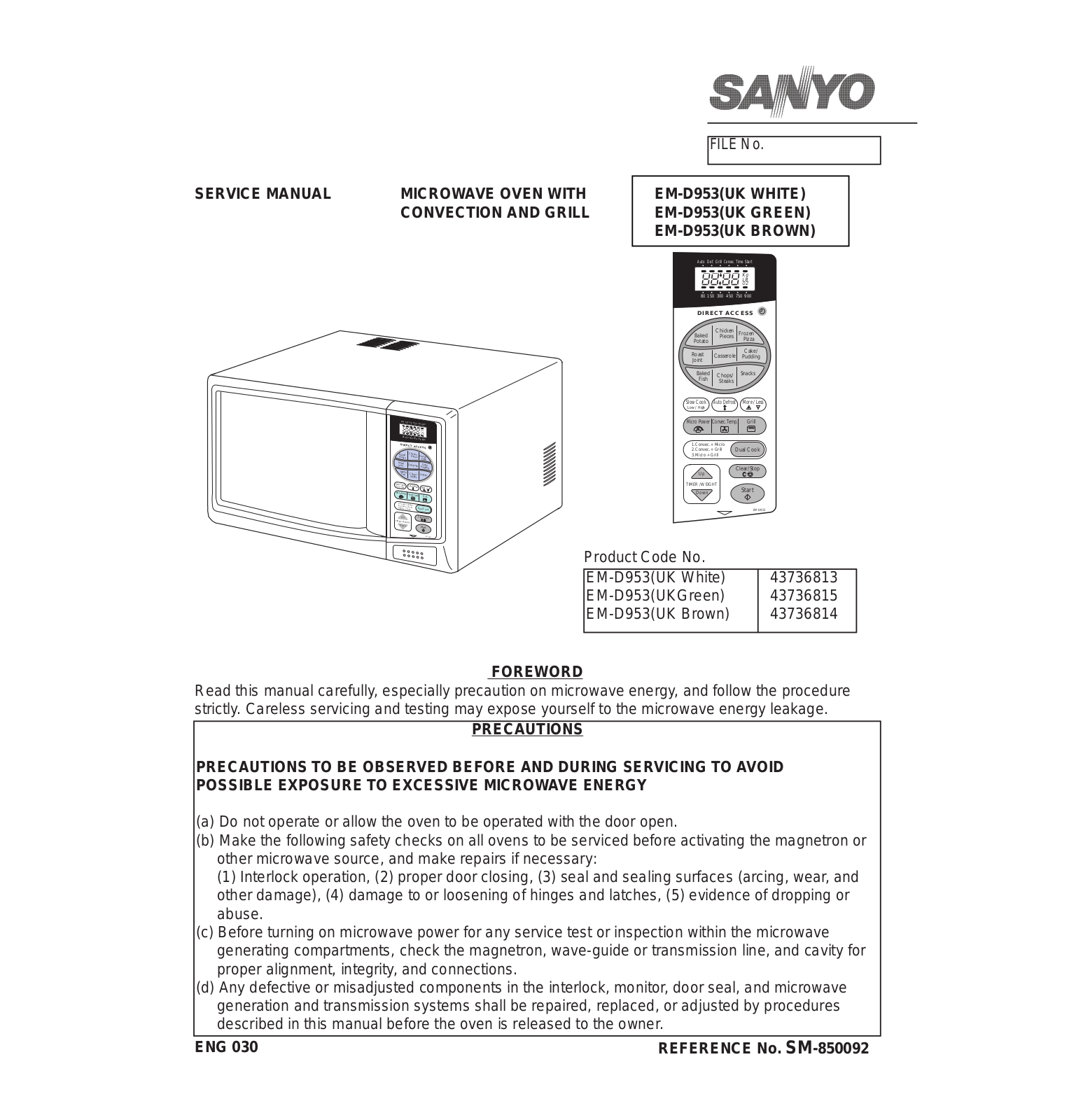
Read this manual carefully, especially precaution on microwave energy, and follow the procedure strictly. Careless servicing and testing may expose yourself to the microwave energy leakage.

PRECAUTIONS

PRECAUTIONS TO BE OBSERVED BEFORE AND DURING SERVICING TO AVOID POSSIBLE EXPOSURE TO EXCESSIVE MICROWAVE ENERGY

(a)Do not operate or allow the oven to be operated with the door open.

(b)Make the following safety checks on all ovens to be serviced before activating the magnetron or other microwave source, and make repairs if necessary:

(1) Interlock operation, (2) proper door closing, (3) seal and sealing surfaces (arcing, wear, and other damage), (4) damage to or loosening of hinges and latches, (5) evidence of dropping or abuse.

(c)Before turning on microwave power for any service test or inspection within the microwave generating compartments, check the magnetron, wave-guide or transmission line, and cavity for proper alignment, integrity, and connections.

(d)Any defective or misadjusted components in the interlock, monitor, door seal, and microwave generation and transmission systems shall be repaired, replaced, or adjusted by procedures described in this manual before the oven is released to the owner.

ENG 030

REFERENCE No. SM-850092


TABLE OF CONTENTS


Adjustment Procedures........................................

1

Circuit Diagram....................................................

4

Specifications.......................................................

2

Test Procedures and Troubleshooting.................

5-15

Power Output Measurement................................

2

Disassembly Instructions.....................................

16-17

Precautions and Repair Service Tips...................

2

Exploded View and Parts list................................

18-23

Oven Control Panel..............................................

3

Control Circuit Board............................................

24


Overall Circuit Diagrams......................................

25


CAUTION

MICROWAVE ENERGY

PERSONNEL SHOULD NOT BE EXPOSED TO

THE MICROWAVE ENERGY WHICH MAY RADI-

ATE FROM THE MAGNETRON OR OTHER

MICROWAVE GENERATING DEVICE IF IT IS

IMPROPERLY USED OR CONNECTED. ALL

INPUT AND OUTPUT MICROWAVE CONNEC-

TIONS, WAVE GUIDES, FLANGES, AND GAS-

KETS MUST BE SECURE. NEVER OPERATE

THE DEVICE WITHOUT A MICROWAVE ENER-

GY ABSORBING LOAD ATTACHED. NEVER

LOOK INTO AN OPEN WAVE GUIDE OR

ANTENNA WHILE THE DEVICE IS ENERGISED.

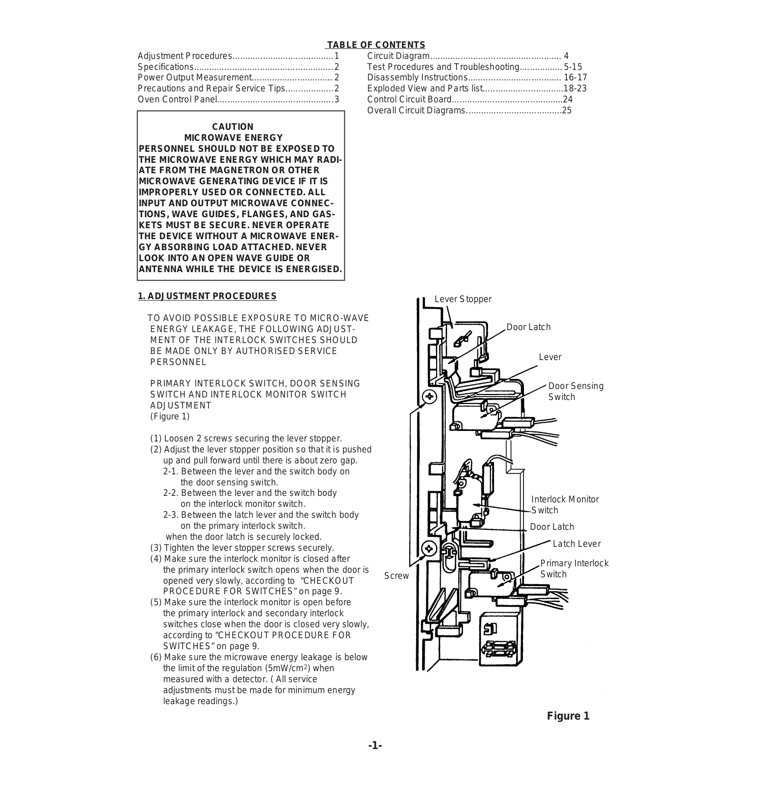
1. ADJUSTMENT PROCEDURES


Lever Stopper


TO AVOID POSSIBLE EXPOSURE TO MICRO-WAVE


ENERGY LEAKAGE, THE FOLLOWING ADJUST-


Door Latch


MENT OF THE INTERLOCK SWITCHES SHOULD


BE MADE ONLY BY AUTHORISED SERVICE


Lever


PERSONNEL


PRIMARY INTERLOCK SWITCH, DOOR SENSING


Door Sensing

SWITCH AND INTERLOCK MONITOR SWITCH


Switch

ADJUSTMENT


(Figure 1)


(1)Loosen 2 screws securing the lever stopper.

(2)Adjust the lever stopper position so that it is pushed up and pull forward until there is about zero gap. 2-1. Between the lever and the switch body on

the door sensing switch.

2-2. Between the lever and the switch body


Interlock Monitor


on the interlock monitor switch.


Switch


2-3. Between the latch lever and the switch body


on the primary interlock switch.


Door Latch

when the door latch is securely locked.


Latch Lever


(3) Tighten the lever stopper screws securely.


(4) Make sure the interlock monitor is closed after


Primary Interlock

the primary interlock switch opens when the door is


Switch

Screw


opened very slowly, according to “CHECKOUT


PROCEDURE FOR SWITCHES” on page 9.


(5) Make sure the interlock monitor is open before


the primary interlock and secondary interlock


switches close when the door is closed very slowly,


according to “CHECKOUT PROCEDURE FOR


SWITCHES” on page 9.


(6) Make sure the microwave energy leakage is below


the limit of the regulation (5mW/cm2) when


measured with a detector. ( All service


adjustments must be made for minimum energy


leakage readings.)


Figure 1

-1-

2. SPECIFICATIONS - EM-D953

Rated Power Consumption........

Microwave 1625W


Convection 1200W


Grill 1300W


Dual 2860W

Microwave Output......................


900W

Frequency..................................


2,450MHz ± 50MHz

Power Supply.............................


230V,50Hz

Rated Current.............................


6.4±10% Amps Micro


(After 15mins.)


5.3±10% Amps Conv.


(After 15mins.)


5.5±10% Amps Grill


(After 15mins.)


11.4±10% Amps Dual


(After 15mins.)

Safety Devices...........................


Thermal Protector for


Magnetron, Open


at 135˚C.


Thermal Protector for


Cavity, Open at 150˚C.


Thermal Protector for


Heater, Open at 122˚C.


Thermal Protector for


Convection, Open at


122˚C


Fuse (Cartridge Type


8A)


Primary Interlock Switch


Door Sensing Switch


Interlock Monitor Switch

Timer..........................................


Electronic Digital


Micro, 90min x 3 Stages


Convection, 90 mins


Grill, 90 mins

Oven Temperature Control.........

Convection,


40˚C-250˚C


Dual,


150˚C-250˚C

Overall Dimensions.........

570(W)x482(D)x355(H)mm

Oven Cavity Size.............

348(W)x344(D)x251(H)mm

Turntable Diameter.....................


325mm

Net Weight..................................


Approx. 24Kg.

3. POWER OUTPUT MEASUREMENT

(1)Prepare 1000±5g tap water.

(2)Adjust water temperature to 10oC±2oC.

(3)Pour water into a container made of borosilicate glass, 190mm outer diameter cylinder, maximum 3mm thickness.

(4)Place the container in the centre of the oven cavity.

(5)Set the heating time for 47 seconds at full power and start the oven.

(6)Take the container out immediately when heating time is up.

(7)Stir water for making even water temperature in the container.

(8)Measure water temperature.

Water temperature rise should be between 8˚C to 12˚C for correct power output.

4.PRECAUTIONS AND REPAIR SERVICE TIPS PRELIMINARY

A.SINCE NEARLY 4,000 VOLTS EXIST IN SOME CIRCUITS OF THIS MICROWAVE OVEN, REPAIRS SHOULD BE CARRIED OUT WITH GREAT CARE

B.TO AVOID POSSIBLE EXPOSURE TO MICROWAVE ENERGY LEAKAGE, THE FOLLOWING PRECAUTIONS MUST BE TAKEN BEFORE SERVICING.

(1)Before the power is applied.

(a)Open and close door several times to make sure the primary interlock switch, the door sensing switch, and the interlock monitor switch operate properly. (Listen for the clicking sound from switches). Make sure the interlock monitor switch is closed after the primary interlock switch is opened, when the door is opened. (See pages 1 and 9).

(b)Make sure the perforated screen and the dielectric choke of the door are correctly mounted.

(2)After the power is applied.

(a)Open and close the door to see if the interlock mechanism operates properly.

(b)Check microwave energy leakage with a leakage detector and confirm the energy leakage is below 5mW/cm2.

(3)Do not operate the unit until it is completely repaired, if any of the following conditions exists.

(a)Door does not close firmly against the cavity front. (b)The hinge is broken.

(c)The choke dielectric or the door seal is damaged. (d)The door is bent or warped, or there is any other

visible damage to the oven that may cause microwave energy leakage.

NOTE: Always keep the seal clean

(e)Make sure there are no defective parts in the microwave generating and transmission assembly. (especially waveguide).

(f)Make sure there are no defective parts in the inter lock mechanism.

(4)Following items should be checked after the unit is repaired.

(a)The interlock monitor switch is connected correctly and firmly.

(b)The magnetron gasket on the magnetron is properly positioned.

(c)Wave guide and oven cavity are intact ( no leakage of microwave energy).

(d)The door can be properly closed and the safety switches work properly.

(e)The oven must be stopped when the door is opened or the time is up.

The oven must not be operated with any of the above components removed or bypassed.

-2-

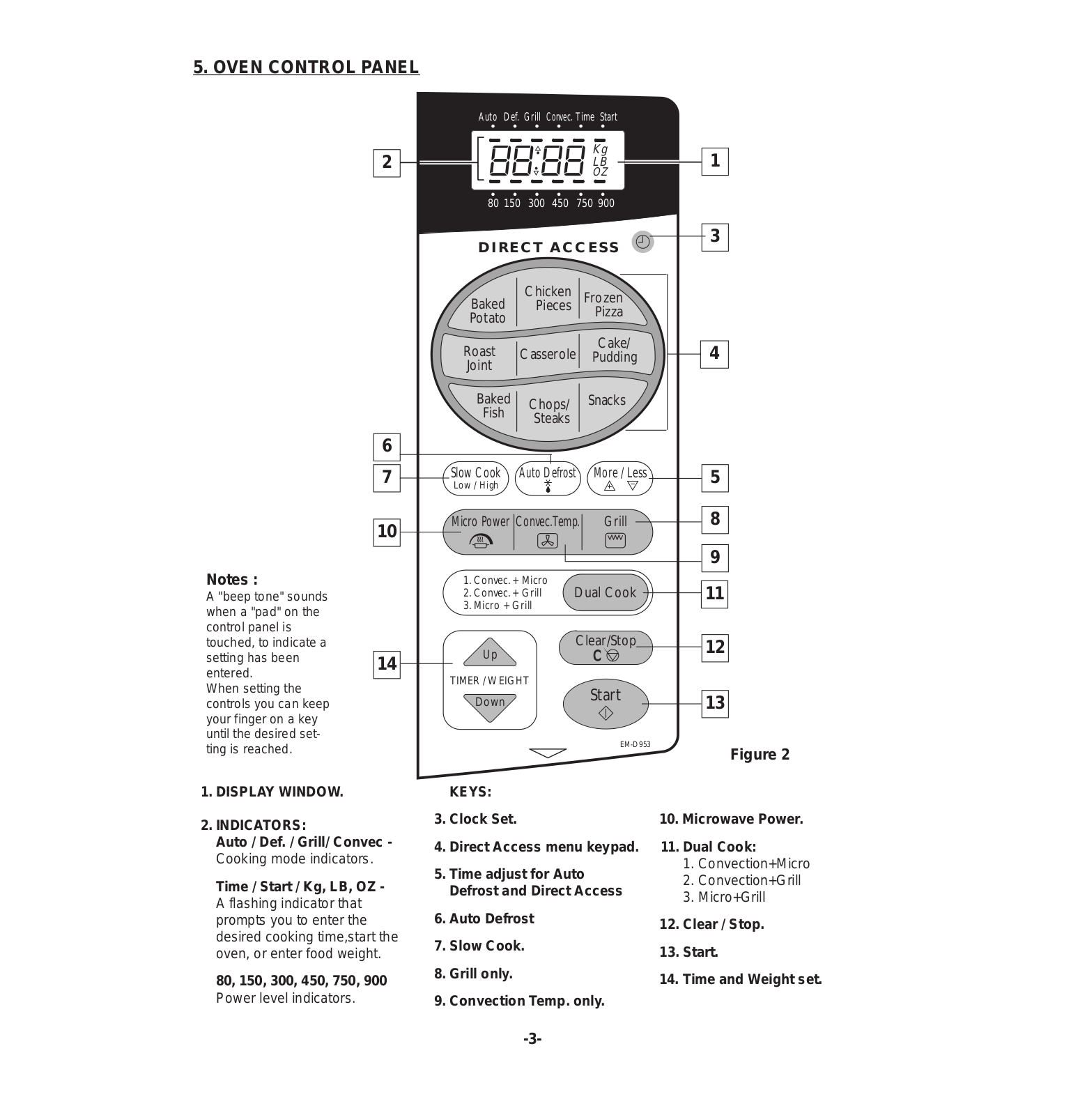
5. OVEN CONTROL PANEL

2

6

7

10

Notes :

A "beep tone" sounds when a "pad" on the control panel is touched, to indicate a

setting has been 14 entered.

When setting the controls you can keep your finger on a key until the desired setting is reached.

1.DISPLAY WINDOW.

2.INDICATORS:

Auto / Def. / Grill/ Convec -

Cooking mode indicators.

Time / Start / Kg, LB, OZ -

A flashing indicator that prompts you to enter the desired cooking time,start the oven, or enter food weight.

80, 150, 300, 450, 750, 900

Power level indicators.

Auto Def. Grill Convec. Time Start


Kg

1


LB


OZ


80 150

300

450

750 900


D I R E C T AC C E S S

3


Baked


Chicken


Frozen


Pieces


Pizza


Potato


Roast

Casserole

Cake/

4

Pudding

Joint


Baked


Chops/


Snacks


Fish


Steaks


Slow Cook

Auto Defrost

More / Less

5

Low / High


Micro Power Convec.Temp.

Grill

8


9

1. Convec. + Micro


Dual Cook

11

2. Convec. + Grill


3. Micro + Grill


Up


Clear/Stop

12


C


TIMER / WEIGHT


Start


Down


13


EM-D953


Figure 2

KEYS:

3.Clock Set.

4.Direct Access menu keypad.

5.Time adjust for Auto Defrost and Direct Access

6.Auto Defrost

7.Slow Cook.

8.Grill only.

9.Convection Temp. only.

10.Microwave Power.

11.Dual Cook:

1.Convection+Micro

2.Convection+Grill

3.Micro+Grill

12.Clear / Stop.

13.Start.

14.Time and Weight set.

-3-

Sanyo EM-D953 Service Manual

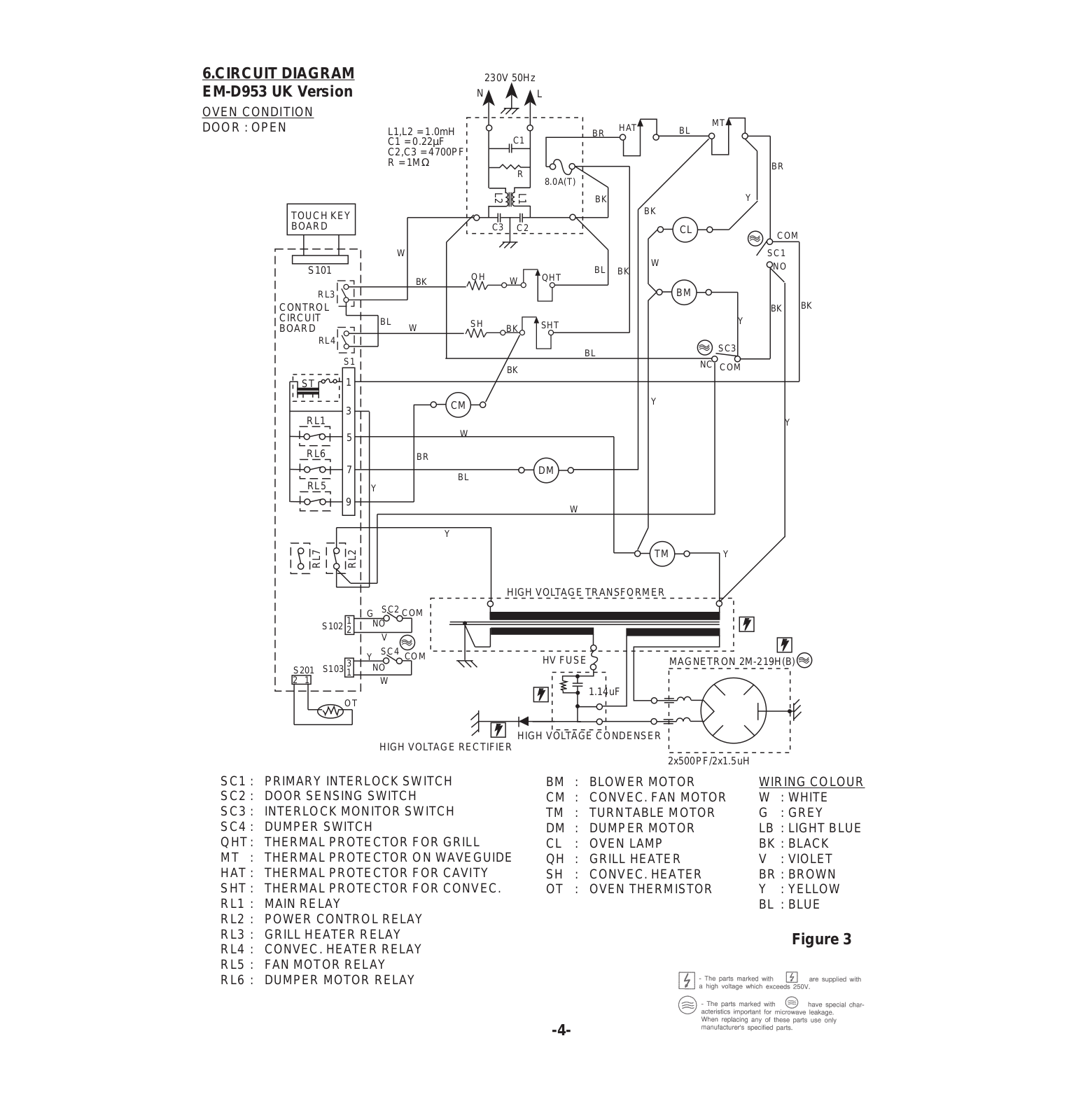
6.CIRCUIT DIAGRAM


230V 50Hz


EM-D953 UK Version


N


L


OVEN CONDITION


MT


DOOR : OPEN


L1,L2 = 1.0mH


BR

HAT

BL


C1 = 0.22µF


C1


C2,C3 = 4700PF


R = 1MΩ


R


BR


8.0A(T)


L2

L1

BK

BK


Y


TOUCH KEY


BOARD


C3

C2


CL

COM


W


W


SC1


S101


BL


NO


BK


QH


BK

W

QHT


BM


RL3


CONTROL


BK

BK

CIRCUIT


BL

SH


SHT


Y


BOARD


W

BK


RL4


SC3


BL


S1


BK


NC COM


ST

1


3


CM


Y


RL1


W


Y


5


RL6


BR


7


BL


DM


RL5


Y


9


W


Y


RL7

RL2


TM


Y


HIGH VOLTAGE TRANSFORMER


1

G

SC2 COM


S102

NO


2


V


3

Y

SC4 COM


HV FUSE

MAGNETRON 2M-219H(B)


S201 S103

NO


1


2 1


W


1.14uF


OT


HIGH VOLTAGE CONDENSER HIGH VOLTAGE RECTIFIER

2x500PF/2x1.5uH

SC1 :

PRIMARY INTERLOCK SWITCH

SC2 :

DOOR SENSING SWITCH

SC3 :

INTERLOCK MONITOR SWITCH

SC4 :

DUMPER SWITCH

QHT :

THERMAL PROTECTOR FOR GRILL

MT :

THERMAL PROTECTOR ON WAVEGUIDE

HAT :

THERMAL PROTECTOR FOR CAVITY

SHT :

THERMAL PROTECTOR FOR CONVEC.

RL1 :

MAIN RELAY

RL2 :

POWER CONTROL RELAY

RL3 :

GRILL HEATER RELAY

RL4 :

CONVEC. HEATER RELAY

RL5 :

FAN MOTOR RELAY

RL6 :

DUMPER MOTOR RELAY

BM : BLOWER MOTOR

WIRING COLOUR

CM

: CONVEC. FAN MOTOR

W

: WHITE

TM

: TURNTABLE MOTOR

G

: GREY

DM

: DUMPER MOTOR

LB : LIGHT BLUE

CL

: OVEN LAMP

BK : BLACK

QH

: GRILL HEATER

V

: VIOLET

SH

: CONVEC. HEATER

BR : BROWN

OT

: OVEN THERMISTOR

Y

: YELLOW


BL : BLUE

Figure 3

-4-

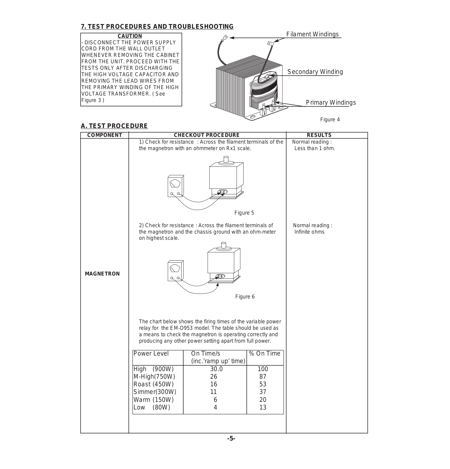
7. TEST PROCEDURES AND TROUBLESHOOTING

CAUTION

- DISCONNECT THE POWER SUPPLY CORD FROM THE WALL OUTLET WHENEVER REMOVING THE CABINET FROM THE UNIT. PROCEED WITH THE TESTS ONLY AFTER DISCHARGING THE HIGH VOLTAGE CAPACITOR AND REMOVING THE LEAD WIRES FROM THE PRIMARY WINDING OF THE HIGH VOLTAGE TRANSFORMER. ( See Figure 3 )

A. TEST PROCEDURE

Filament Windings

Secondary Winding

Primary Windings

Figure 4

COMPONENT


CHECKOUT PROCEDURE

RESULTS


1) Check for resistance : Across the filament terminals of the

Normal reading :


the magnetron with an ohmmeter on Rx1 scale.

Less than 1 ohm.


Figure 5


2) Check for resistance : Across the filament terminals of

Normal reading :

the magnetron and the chassis ground with an ohm-meter

Infinite ohms

on highest scale.


MAGNETRON

Figure 6

The chart below shows the firing times of the variable power relay for the EM-D953 model. The table should be used as a means to check the magnetron is operating correctly and producing any other power setting apart from full power.

Power Level

On Time/s

% On Time


(inc.’ramp up’ time)


High

(900W)

30.0

100

M-High(750W)

26

87

Roast (450W)

16

53

Simmer(300W)

11

37

Warm (150W)

6

20

Low

(80W)

4

13


-5-

COMPONENT

CHECKOUT PROCEDURE

RESULTS


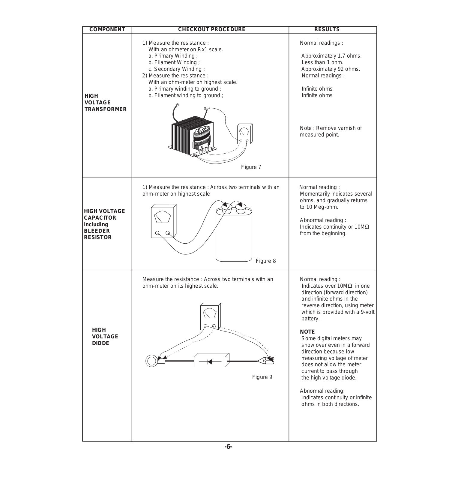
1) Measure the resistance :

Normal readings :


With an ohmeter on Rx1 scale.


a. Primary Winding ;

Approximately 1.7 ohms.


b. Filament Winding ;

Less than 1 ohm.


c. Secondary Winding ;

Approximately 92 ohms.


2) Measure the resistance :

Normal readings :


With an ohm-meter on highest scale.


a. Primary winding to ground ;

Infinite ohms

HIGH

b. Filament winding to ground ;

Infinite ohms

VOLTAGE


TRANSFORMER


Note : Remove varnish of


measured point.


Figure 7


1) Measure the resistance : Across two terminals with an

Normal reading :


ohm-meter on highest scale

Momentarily indicates several


ohms, and gradually returns


to 10 Meg-ohm.


HIGH VOLTAGE


CAPACITOR


Abnormal reading :


including


Indicates continuity or 10MΩ


BLEEDER


from the beginning.


RESISTOR


Figure

8


Measure the resistance : Across two terminals with an

Normal reading :


ohm-meter on its highest scale.

Indicates over 10MΩ in one


direction (forward direction)


and infinite ohms in the


reverse direction, using meter


which is provided with a 9-volt


battery.


HIGH


NOTE


VOLTAGE


Some digital meters may


DIODE


show over even in a forward


direction because low


measuring voltage of meter


does not allow the meter


current to pass through


Figure 9


the high voltage diode.


Abnormal reading:


Indicates continuity or infinite


ohms in both directions.

-6-


COMPONENT


CHECKOUT PROCEDURE


RESULT


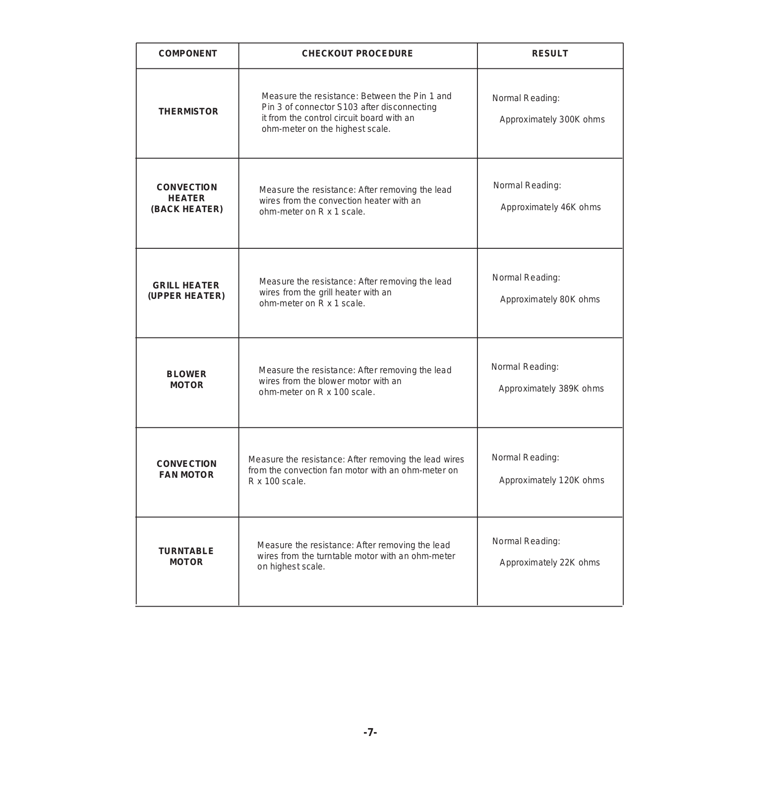
Measure the resistance: Between the Pin 1 and


Normal Reading:


THERMISTOR


Pin 3 of connector S103 after disconnecting


it from the control circuit board with an


Approximately 300K ohms


ohm-meter on the highest scale.


Normal Reading:


CONVECTION


Measure the resistance: After removing the lead


HEATER


wires from the convection heater with an


Approximately 46K ohms


(BACK HEATER)


ohm-meter on R x 1 scale.


Normal Reading:


Measure the resistance: After removing the lead


GRILL HEATER


wires from the grill heater with an


(UPPER HEATER)


Approximately 80K ohms


ohm-meter on R x 1 scale.


Normal Reading:


Measure the resistance: After removing the lead


BLOWER


wires from the blower motor with an


MOTOR


Approximately 389K ohms


ohm-meter on R x 100 scale.


Normal Reading:


Measure the resistance: After removing the lead wires


CONVECTION


from the convection fan motor with an ohm-meter on


FAN MOTOR


Approximately 120K ohms


R x 100 scale.


Normal Reading:


Measure the resistance: After removing the lead


TURNTABLE


wires from the turntable motor with an ohm-meter


MOTOR


Approximately 22K ohms


on highest scale.


-7-

COMPONENT

CHECKOUT PROCEDURE

RESULTS

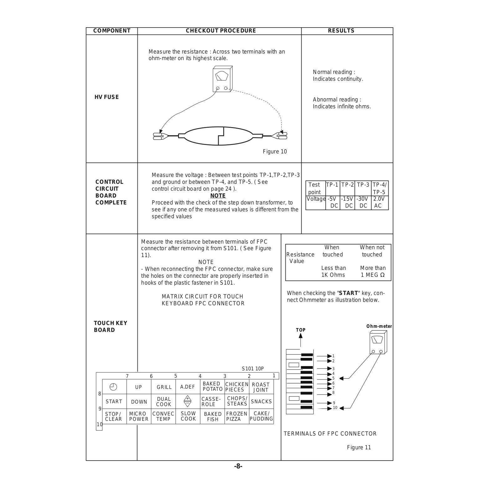
Measure the resistance : Across two terminals with an ohm-meter on its highest scale.

Normal reading :

Indicates continuity.

HV FUSE

Abnormal reading :


Indicates infinite ohms.


Figure 10


Measure the voltage : Between test points TP-1,TP-2,TP-3


and ground or between TP-4, and TP-5. ( See


CONTROL


Test


TP-1

TP-2

TP-3

TP-4/


CIRCUIT


control circuit board on page 24 ).


point


TP-5


BOARD


NOTE


Voltage

-5V

-15V

-30V

2.0V


COMPLETE


Proceed with the check of the step down transformer, to


DC

DC

DC

AC


see if any one of the measured values is different from the


specified values


Measure the resistance between terminals of FPC


connector after removing it from S101. ( See Figure


When

When not


11).


Resistance

touched

touched


NOTE


Value


Less than

More than


- When reconnecting the FPC connector, make sure


the holes on the connector are properly inserted in


1K Ohms

1 MEG Ω


hooks of the plastic fastener in S101.


MATRIX CIRCUIT FOR TOUCH


When checking the "START" key, con-


nect Ohmmeter as illustration below.


KEYBOARD FPC CONNECTOR


TOUCH KEY


Ohm-meter


BOARD


TOP


1A1


2A2


S101 10P


A3


3


A4


7


6

5


4

3

2


1


4


A5


5


C1


UP


GRILL

A.DEF

BAKED

CHICKEN ROAST


6


7


POTATO PIECES

JOINT


C2


8


8


C3


START

DOWN


DUAL


CASSE-

CHOPS/

SNACKS


9C4


COOK


ROLE

STEAKS


9


10C5


STOP/

MICRO

CONVEC

SLOW

BAKED

FROZEN

CAKE/


10

CLEAR

POWER


TEMP

COOK

FISH

PIZZA

PUDDING


TERMINALS OF FPC CONNECTOR


Figure 11


-8-

Loading...
+ 18 hidden pages