

Page 1

FILE NO.
R
Service Manual
DVD Video Player
DVD-SL30 (US)
Supplement
PRODUCT CODE No.
137 116 00
The construction of model DVD-SL30(US) is similar to model DWM-380(US). The differences between these models require the
bellow specified items. Please also refer to the original service manual DWM-380(US) (SM5810254) for other items.
CONTENTS
Service Mode ................................................................... 1
How to load software for MPEG P.W.Board .................... 1
Wiring Connection ............................................................ 1
Exploded View (Cabinet & Chassis) ................................ 2
Parts List .......................................................................... 3
Exploded view (DVD Mechanism) ................................... 5
Parts List .......................................................................... 5
Schematic Diagram (Front, Dengen and Power Sw) ....... 6
Wiring Diagram (Front, Dengen and Power Sw) .............. 8
Mar. / '02 BB Printed in Japan.
SANYO FISHER SERVICE CORPORATION
REFERENCE No. SS5810274
Page 2
SERVICE MODE
Page 8
2. Displaying Internal Setup screen
Push NEXT button within three seconds after operating the Service
Mode display.
On the Internal Setup screen shown on the right, set up Market and
Region.
HOW TO LOAD SOFTWARE FOR MPEG P.W.BOARD
Page 10
1. Power on, then open tray.
2. It take on CD-ROM for UPDATE software to the tray, and tray close.
3. Display " UP DATE" in the TV screen.
4. For the time being, tray open and FL display remain "UP DATE".
5. When software loading finished, FL display "STANDBY".
6. Next, set up market code and region code by "SERVICE MODE"
CD-ROM part code is "0PRADF7114--AD".
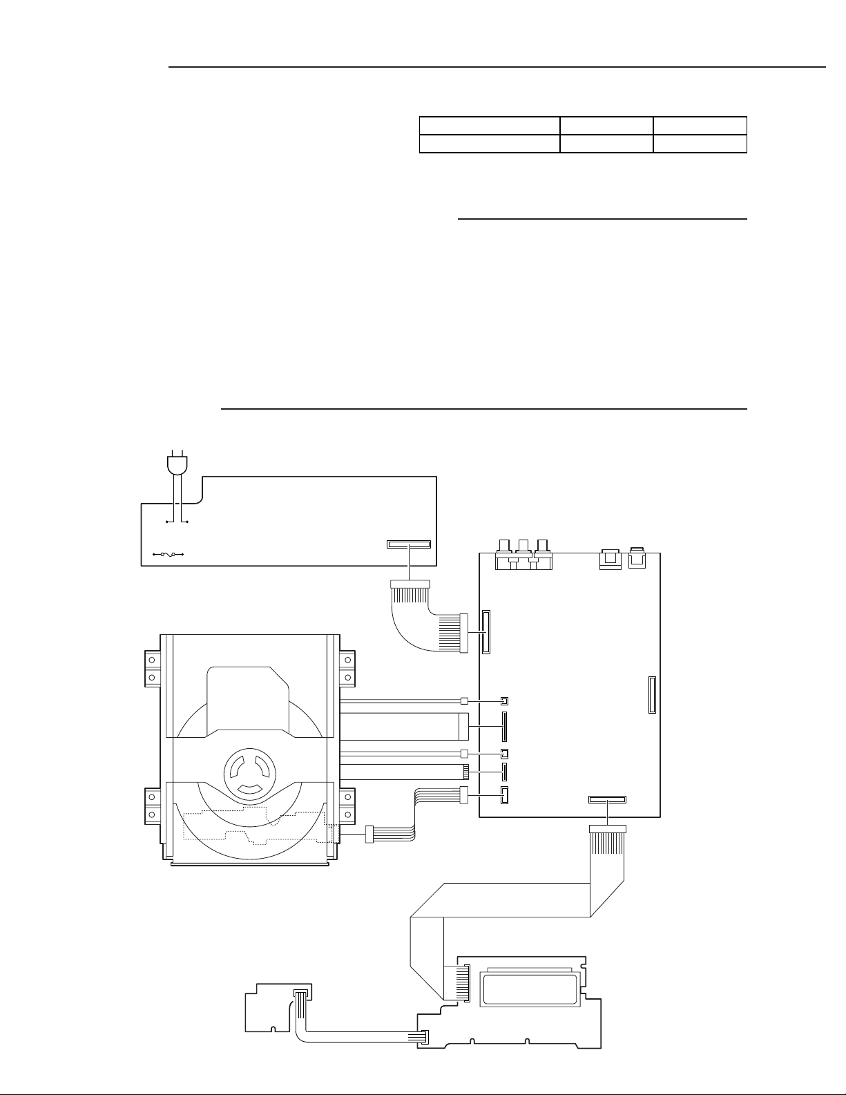
WIRING CONNECTION
Page 29
AC IN
Model
DVD SL30/US
Market Region
SFC 1
Market/Rejion setup table.
WH
CN491CN490
FU490
1A L 125V
DVD MECHANISM
DENGEN P.W.B
CN481
(14P)
SLED MOTOR
PICK-UP
LIMIT SWITCH
SPINDLE MOTOR
CN001
(5P)
LOADING MOTOR &
OPEN/CLOSE SWITCH
AUDIO VIDEO
OUT
CN870
CN811
(14P)
CN161
(2P)
CN100
(33P)
CN150
(2P)
CN162
(11P)
CN160
(5P)
S-VIDEO
OUT
CN872 CN871
DVD/MPEG P.W.B
CN814
(14P)
DIGITAL
OUT
CN895
(12P)
POWER
SW
P. W. B
CN640
(4P)
- 1 -
CN604
(4P)
CN601
(14P)
FL601
FRONT P.W.B
Page 3
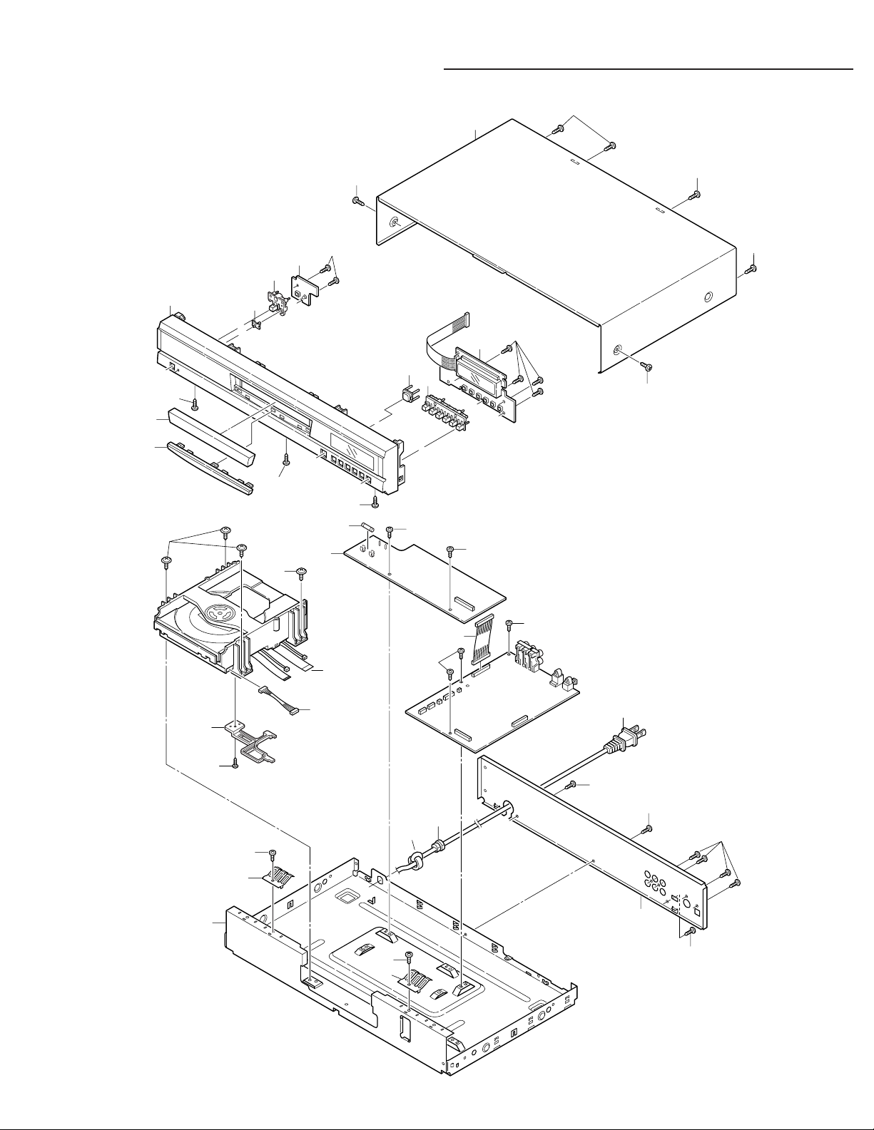
EXPLODED VIEW (CABINET & CHASSIS)
Page 11
Y04
9
3
4
Y05
1
Y01
Y04
Y04
71
Y04
Y02
6
5
Y03
72
7
8
Y04
Y01
Y01
51
73
Y05
Y07
Y07
10
Y06
11
Y09
12
55
54
Y09
12
56
Y08
13
52
Y08
DVD,MPEG P.W.BOARD ASSY
The same as the DWM-380/US.
53
Y10
Y10
Y11
14
Y10
- 2 -
Page 4

PARTS LIST
Page 12
PRODUCT SAFETY NOTICE
EACH PRECAUTION IN THIS MANUAL SHOULD BE FOLLOWED DURING SERVICING. COMPONENTS IDENTIFIED WITH THE IEC
!!
SYMBOL
SPECIAL SIGNIFICANCE. WHEN REPLACING A COMPONENT IDENTIFIED BY
OR PARTS WITH THE SAME RATINGS OF RESISTANCE, WATTAGE OR VOLTAGE THAT ARE DESIGNATED IN THE PARTS LIST IN
THIS MANUAL. LEAKAGE-CURRENT OR RESISTANCE MEASUREMENTS MUST BE MADE TO DETERMINE THAT EXPOSED PARTS
ARE ACCEPTABLY INSULATED FROM THE SUPPLY CIRCUIT BEFORE RETURNING THE PRODUCT TO THE CUSTOMER.
CAUTION : Regular type resistors and capacitors are not listed. To know those values, refer to the schematic diagram.
!
IN THE PARTS LIST AND THE SCHEMATIC DIAGRAM DESIGNATED COMPONENTS IN WHICH SAFETY CAN BE OF
!!
!
, USE ONLY THE REPLACEMENT PARTS DESIGNATED,
Regular type resistors are less than 1/4W carbon type and chip resistors.
Regular type capacitors are less than 50V and less than 1000µF of Ceramic type and Electrolytic type.
PACKING & ACCESSORIES
REF.NO. PART NO. DESCRIPTION
614 323 2506 CARTON CASE,INNER
614 315 5928 CUSHION,LEFT,LEFT
614 315 5935 CUSHION,RIGHT,RIGHT
614 323 2520 INSTRUCTION MANUAL,INST
645 052 1621 POLY BAG,CABLE
645 012 2958 POLY BAG,INST MANUAL
645 044 8539 POLY SHEET,SET
645 051 6047 REMOCON,REM-SL30MT
645 043 9735 BATTERY COVER,SERVICE PART
645 037 3893 CABLE,A/V
or 645 023 0806 CABLE,A/V
or 645 017 6012 CABLE,A/V
or 645 003 3414 CABLE,A/V
CABINET & CHASSIS
REF.NO. PART NO. DESCRIPTION
1 614 324 1607 ASSY,CABINET,FRONT
3 614 316 7563 DEC,DVD TRAY
4 614 316 7549 DEC,ESCUTCHEON,
UNDER DVD TRAY
5 614 302 0530 DEC,WINDOW LED,STANDBY
6 614 315 5768 BUTTON,POWER
7 614 316 7556 DEC,WINDOW,IR
8 614 317 9498 BUTTON,PLAY,PLAY/STOP
9 614 317 9344 ASSY,CABINET,BENDING,
AFTER BENDING
10 614 320 5852 MOUNTING,FFC
11 614 323 2599 ASSY,CABINET,BOTTOM
12 614 313 6545 SPRING,PLATE,SHIELD
13 614 129 1901 FIXER,AC CORD
or 614 284 1884 FIXER,AC CORD
14 614 323 0090 PANEL,REAR
FIXING PARTS
REF.NO. PART NO. DESCRIPTION
Y01 411 021 6405 SCR S-TPG BIN 3X8,
FRONT-BOTTOM FIX
Y02 411 165 3803 SCR S-TPG BIN 2.3X10,
STANDBY PWB FIX
Y03 411 165 3803 SCR S-TPG BIN 2.3X10,
FRONT PWB FIX
Y04 411 098 4205 SCR S-TPG BIN 3X8,CABINET
Y05 411 020 9803 SCR S-TPG BRZ+FLG 3X6,
DVD MECHA
Y06 411 021 2704 SCR S-TPG BIN 2.6X6,MOUNTING
Y07 411 021 6405 SCR S-TPG BIN 3X8,MAIN PWB
Y08 411 021 6405 SCR S-TPG BIN 3X8,MPEG PWB
Y09 411 021 6405 SCR S-TPG BIN 3X8,
BOTTOM-SPRING FIX
Y10 411 021 3503 SCR S-TPG BIN 3X10,BOTTOM-REAR
Y11 411 021 3503 SCR S-TPG BIN 3X10,
REAR-ELECT PART
ELECTRICAL-PARTS
REF.NO. PART NO. DESCRIPTION
51 423 027 4606 FUSE 125V 1A,125V 1A
52 614 323 3206 ASSY,WIRE,DVD-DG 14P
53 645 032 7537 CORD,POWER-1.86MK,FOR US
54 645 052 5865 FLEXIBLE FLAT CABLE,PICK,FFC 33P
55 614 323 3237 ASSY,WIRE,LOADING-DVD 5P
56 645 051 0649 CORE,FERRITE,AC_CORD
or 645 031 7637 CORE,FERRITE,AC_CORD
POWER-SW P.W.BOARD ASSY
REF.NO. PART NO. DESCRIPTION
71 614 323 3695 ASSY,PWB POWER-SW(Only initial)
CN640 614 035 4935 SOCKET,DIP 4P,TO_FRONT
D6401 408 032 5404 LED SLP-9118C-51H-S-T1,STANDBY
D6402 407 012 4406 DIODE 1SS133
S6401 645 048 3820 SWITCH,PUSH
or 614 220 5471 SWITCH,TACT
or 614 240 1002 SWITCH,TACT
or 645 006 5958 SWITCH,PUSH 1P-1T
FRONT P.W.BOARD ASSY
REF.NO. PART NO. DESCRIPTION
72 614 323 1912 ASSY,PWB FRONT(Only initial)
BR601 614 315 5843 HOLDER,FL
CN601 614 323 3213 ASSY,WIRE,FRONT_DVD
CN604 614 035 4935 SOCKET,DIP 4P,TO_POWER_SW
D6040 407 012 4406 DIODE 1SS133
D6041 407 012 4406 DIODE 1SS133
D6042 407 012 4406 DIODE 1SS133
D6043 407 012 4406 DIODE 1SS133
D6044 407 012 4406 DIODE 1SS133
D6045 407 012 4406 DIODE 1SS133
DS601 407 217 8407 PHOTO DIODE SPS-440-1-G
FL601 645 044 8232 FLUORESCENT TUBE
IC601 409 519 6907 IC PT6315
S6040 645 048 3820 SWITCH,PUSH
or 614 220 5471 SWITCH,TACT
or 614 240 1002 SWITCH,TACT
or 645 006 5958 SWITCH,PUSH 1P-1T
S6041 645 048 3820 SWITCH,PUSH
or 614 220 5471 SWITCH,TACT
or 614 240 1002 SWITCH,TACT
or 645 006 5958 SWITCH,PUSH 1P-1T
S6042 645 048 3820 SWITCH,PUSH
or 614 220 5471 SWITCH,TACT
or 614 240 1002 SWITCH,TACT
or 645 006 5958 SWITCH,PUSH 1P-1T
S6043 645 048 3820 SWITCH,PUSH
or 614 220 5471 SWITCH,TACT
or 614 240 1002 SWITCH,TACT
or 645 006 5958 SWITCH,PUSH 1P-1T
S6044 645 048 3820 SWITCH,PUSH
or 614 220 5471 SWITCH,TACT
or 614 240 1002 SWITCH,TACT
or 645 006 5958 SWITCH,PUSH 1P-1T
- 3 -
Page 5

PARTS LIST
REF.NO. PART NO. DESCRIPTION REF.NO. PART NO. DESCRIPTION
S6045 645 048 3820 SWITCH,PUSH
or 614 220 5471 SWITCH,TACT
or 614 240 1002 SWITCH,TACT
or 645 006 5958 SWITCH,PUSH 1P-1T
DENGEN P.W.BOARD ASSY
REF.NO. PART NO. DESCRIPTION
73 614 323 1929 ASSY,PWB DENGEN(Only initial)
C4809 403 357 8406 ELECT 1000U M 6.3V
C4811 403 337 2103 ELECT 100U M 10V
or 403 373 8305 ELECT 100U M 10V
C4812 403 337 5500 ELECT 22U M 50V
or 403 374 0704 ELECT 22U M 50V
C4814 403 373 8800 ELECT 330U M 16V
C4815 403 337 7207 ELECT 33U M 35V
or 403 374 0001 ELECT 33U M 35V
C4902 403 082 0201 POLYPRO 470P J 100V
C4903 403 332 7202 ELECT 47U M 25V
or 403 373 9203 ELECT 47U M 25V
C4904 403 145 9103 CERAMIC 220P K 1K
C4906 404 088 7409 MT-POLYEST 0.1U K 250V
or 404 080 8206 MT-POLYEST 0.1U K 250V
or 403 376 2409 MT-POLYEST 0.1U M 250V
C4907 404 088 7409 MT-POLYEST 0.1U K 250V
or 404 080 8206 MT-POLYEST 0.1U K 250V
or 403 376 2409 MT-POLYEST 0.1U M 250V
C4908 404 080 8107 CERAMIC 2200P M 400V
CN481 614 310 2557 PLUG,14P
or 645 006 0892 PLUG,14P
D4802 408 043 6704 DIODE RGP10GL-22C-012
D4803 408 044 7304 DIODE SB160L-19C2-004
D4805 408 043 6704 DIODE RGP10GL-22C-012
D4806 408 043 6704 DIODE RGP10GL-22C-012
D4807 407 099 4603 ZENER DIODE MTZJ3.9B
D4809 408 044 6307 DIODE SB140L 19C2-004
D4820 407 099 6607 ZENER DIODE MTZJ12B
D4902 407 012 4406 DIODE 1SS133
D4904 407 004 9808 DIODE DSK10E
or 407 012 0408 DIODE 1N4004
or 407 004 9808 DIODE DSK10E
D4905 407 004 9808 DIODE DSK10E
or 407 012 0408 DIODE 1N4004
or 407 004 9808 DIODE DSK10E
D4906 407 004 9808 DIODE DSK10E
or 407 012 0408 DIODE 1N4004
or 407 004 9808 DIODE DSK10E
D4907 407 004 9808 DIODE DSK10E
or 407 012 0408 DIODE 1N4004
or 407 004 9808 DIODE DSK10E
D4910 407 012 4406 DIODE 1SS133
FPC01 645 006 4760 HOLDER,FUSE
or 645 031 7903 HOLDER,FUSE
FPC02 645 006 4760 HOLDER,FUSE
or 645 031 7903 HOLDER,FUSE
IC483 409 517 5704 IC KA431AZTF
or 409 508 2804 IC KIA431A
or 409 508 2705 IC KIA431
or 409 067 7203 IC L5431
IC490 410 431 1208 IC STR-G6351 LF1129
L4801 645 048 4469 INDUCTOR,22U
or 645 045 8613 INDUCTOR,10U
L4900 645 045 8941 LINE FILTER
or 645 038 2024 LINE FILTER
PC490 408 047 0005 PHOTO COUPLE H11A817B300
or 407 220 4601 PHOTO COUPLE PC123Y22
or 407 104 2204 PHOTO COUPLE PC817B
or 407 203 8602 PC PS2561-1-V
PR481 645 042 2553 PROTECTOR,0.63A 125V
PR482 645 042 2560 PROTECTOR,0.75A 125V
PR484 645 042 2553 PROTECTOR,0.63A 125V
PT490 645 045 6473 TRANS,POWER,PULSE
Q4820 405 141 3109 TR KTC3203-Y
or 405 024 9907 TR 2SD734-F
or 405 025 0200 TR 2SD734-G
R4908 402 087 3408 RESISTOR 3.3M J- 1/2W
or 402 078 9501 CARBON 3.3M J- 1/2W
or 402 078 8108 CARBON 3.3M J- 1/2W
WR490 614 017 6964 TERMINAL BOARD
WR491 614 017 6964 TERMINAL BOARD
- 4 -
Page 6

EXPLODED VIEW(DVD MECHANISM)
Page15
DM05
DM09
DM08
DM04
DM06
DM07
DM12
DM01
DM02
DM03
DM13
DM14
MECHA SW P.W.Board
The same as the DWM-380/US
DM19
DM17
DM18
DM17
DM18
DM37
DM20
DM21
DM22
DM23
DM38
DM17
DM18
DM24
DM25
DM17
DM18
DM26
DM27
DM28
DM29
DM30
DM32
DM36
DM33
DM34
DM39
DM11
PARTS LIST
DVD MECHANISM
REF.NO. PART NO. DESCRIPTION
614 323 2988 ASSY,MECHA,LDR310,
MECHANISM ASSY
DM01 411 162 1901 SCR S-TPG PAN PCS 2X3,
CHUCK HOLDER FIX
DM02 614 315 7830 DISC,CHUCK DISC
DM03 614 320 2356 SLIDE,BASE UP/DOWN
DM04 614 323 3923 BELT,SQUARE,LOADING
DM05 614 320 2271 GEAR,LOADING GEAR
DM06 412 061 7803 SPECIAL SCREW,HOLDER RAIL FIX
DM07 614 320 2349 PULLEY,LOADING RETARD PULLY
DM08 614 320 3865 CHASSIS,LOADING CHASSIS
DM09 614 320 2363 TRAY,TRAY
DM11 411 021 2704 SCR S-TPG BIN 2.6X6,
PWB MECHA IF FIX
DM12 645 032 4352 ASSY,MOTOR LOADING,
LOADING MOTOR
DM13 645 050 0725 MAGNET(CHUCK),MAGNET CHUCK
or 645 043 7175 MAGNET(CHUCK),MAGNET CHUCK
DM14 614 315 7847 HOLDER,CHUCK HOLDER
DM17 411 021 1806 SCR S-TPG BIN 2.6X10,BASE FIX
DM18 411 092 0906 WASHER Z 2.6X10X0.5,BASE FIX
DM19 614 321 0610 ASSY,MECHA,
LDR 370 BASE,BASE MECHANISM
DM20 411 184 0302 SCR S-TPG PAN PCS 1.7X4.5,
RACK FIX
DM21 614 310 2083 GEAR,RACK,MOVE PICKUP(FREE)
DM22 614 310 6159 SPRING,COMP,
FOR BACK RUSH(RACK)
DM23 614 310 2076 GEAR,RACK,MOVE PICKUP(FIX)
DM24 411 018 4704 SCR PAN PCS 1.7X5,LIMIT SW FIX
DM25 645 040 9899 SWITCH,MICRO 1P-2T,LIMIT SW
REF.NO. PART NO. DESCRIPTION
DM26 412 057 8304 SPECIAL WASHER,FOR GEAR FIX
DM27 614 310 2069 GEAR,GEAR-5
DM28 614 310 6142 SPRING,COMP,FOR BACK RUSH
DM29 614 310 2052 GEAR.,GEAR-4
DM30 412 057 8304 SPECIAL WASHER,FOR GEAR FIX
DM32 614 310 2038 GEAR.,GEAR-2
DM33 411 106 7709 SCR PAN PCS 1.7X2.5,
SLED MOTOR FIX
DM34 645 051 5200 ASSY,MOTOR,SLED MOTOR
DM36 614 310 2045 GEAR.,GEAR-3
DM37 614 320 5098 MOUNTING,BASE MECHA MOUNTING
DM38 614 310 6128 SPACER,MECHA,
BASE MECHA FLOATING
DM39 614 322 9070 SPACER,MECHA,
BASE MECHA FLOATING
- 5 -
Page 7

SCHEMATIC DIAGRAM (FRONT , DENGEN and POWER SW)
Page 40
1AD4B10D1300C
R6032
4.7K
C6032
D6401
S6401
POWER
DS601
SPS-440-1G
54
123
S5
R6001
R6002
R6003
R6004
R6005
R6006
R6007
S7
S6
FL601
82K
2.2K
DOUT
100K
DIN
100K
CLK
100K
STB
KEY1
10K
S8
10K
S9
S10
S11
1AV4T41B06000
1AV4T41B060001AV4T41B06000
R6031
47
220P
C6031
10/25
STANDBY
330
R6401
D6402
1SS133
12 31 324567891011121314151617181920212223242526272829
3
2
1
CN640
CN604
44
3
2
1
S12
KEY2
S4
S3
S2
S1
S12
S13
1234567891011
C6003
LED1
LED2
LED3
LED4
OSC
DOUT
DIN
CLK
STB
KEY1
KEY2
S14
G1G2G3G4G5
0.01
G1G2G3
VSS
VDD
IC601
VDD
VSS
S2/K2
S1/K1
12 13 14 15 16 17 18 19 20 21 22
S1S2S3S4S5S6S7
0.01
C6004
G8
S18
S17
S16
S15
FROM DVD PWB(CN814)
+5V
STB
VFD_CLK
1234567891011121314
STB
CLK
DOUT
G8
G7
G6
3435363738394041424344
PT6315
S3/K3
G7
G4
S4/K4
G6
S24/G5
S5/K5
G5
S22/G7
S22/G6
S7/K7
S6/K6
G3
G4
S20/G9
S19/G8
S18/G11
S17/G12
S16/K16
S15/K15
S14/K14
S13/K13
S12/K12
S11/K11
S10/K10
S8/K8
S8
S9
G1
G2
NC
GND
DATA_IN
DATA_OUT
DIN
S19/G10
VEE
23 24 25 26 27 28 29 30 31 32 33
S9/K9
S6045
OPEN/
CLOSE
S6044
PLAY
S6043
PAUSE
S6042
STOP
S6041
BSKIP
S6040
FSKIP
IR
+5.6V
P_MUTE
S18
S17
S16
S15
S14
S13
S12
S11
S10KEY2
D6045
1SS133
D6044
1SS133
D6043
1SS133
D6042
1SS133
D6041
1SS133
D6040
1SS133
1AD4B10D1300A
-30V
P-CON
C6001
47/10
KEY1
KEY2
FL1
14
FL2
CN601
TO DVD PWB(CN811)
FL1
+12V
+9V
+5.6V
-30V
FL2
FL1
FL2
14
FL2
13
FL1
C4801
47/25
-30V
12
-30V
P-CON
RF_GND
10
11
KTC3203
C4820
1.5K
R4800
D4807
MTZJ3.9B
D_GND
D_GND
7
8
9
Q4820
0.01
C4821
D4820
MTZJ12B
IC483
KA431AZTF
C4807
1.2K
1/50
R4802
R4807
6.8
+9V
D_GND
6
+9V
R4820
10/50
321
R4808
C4808
0.022
R4806
6.8
+5.6V
5
+5.6V
2.2K
10
4.7K
R4805
+5.6V
4
0.01
C4822
L4801
C4810
100/16
R4809
R4804
V_GND
A_GND
2
3
D4802
RGP10G
C4815
33/35
10
C4814
330/16
P
1K
R4810
PC490
220
C4812
P
4.7K
D4806
RGP10G
P
C4811
100/10
(MV-WX)
14
+12V
CN481
1
+12V
PR484
630
P
(MV-WX)
D4803
SB160
(MV-WX)
D4809
SB140
C4809
P
D4805PR481
RGP10G630
22/50
(MV-WX)
PR482
14
13
12
(MV-WX)
1000/6.3
11
10
9
8
750
7
PT490
1AV4L51B4070N
1
2
3
4
5
6
R4900
47
PRODUCT SAFETY NOTICE
Each precaution in this manual should be followed during servicing. Components identified with the
IEC symbol
can be of special significance. When replacing a component identified by
in the parts list and the schematic diagram designated components in which safety
!!
!
!!
!
, use only the replacement
parts designated, or parts with the same ratings of resistance, wattage or voltage that are designated
in the parts list in this manual. Leakage-current or resistance measurements must be made to
determine that exposed parts are acceptably insulated from the supply circuit before returning the
product to the customer.
This is a basic schematic diagram.
IC490
STR-G6351
GND
VIN
DRAIN
SOURSE
D4902
1SS133
470P
C4902
H11A817B
- 7 -- 6 -
R4903
D4910
PC490
R4904
3.3K
1SS133
680
C4910
C4903
O.C.P/F.B
47/25
R4913
0.01
2.2
P
(MV-WX)
2.2
R4905
12345
R4914
C4905
33/200
(1KV)
C4904
220P
2.2
2.2
R4915
D4904 D4905
DSK10E DSK10E
R4918R4919
(1/4W)(1/4W)
18K18K
D4907D4906
DSK10EDSK10E
C4906
(AC250V)
0.1
R4916R4917
18K
18K
(1/4W)(1/4W)
C4908
2200P
L4900
(400V)
FU490
1A
1AD4F35B0950N
(1/2W)
0.1
C4907
R4908
(AC250V)
3.3M
WR491
1AD4B10D1300B
WH
WR490
Page 8

WIRING DIAGRAM (FRONT , DENGEN and POWER SW)
Page 42
BC DEFGH
BC DEFGH
RISK OF FIRE-REPLACE
FUSE AS MARKED
R4908
FU490
1A 125V
C4907
F
_A _V
WR490
WR491
WH
F
V
A
CAUTION : FOR CONTINUED PROTECTION AGAINST FIRE HAZARD,
REPLACE ONLY WITH THE SAME TYPE FUSE
1A 125V (FU490) .
AT TENTION :POUR UNE PROTECTION CONTINUE LES RISOUES D’INCEIE
N’UTLISER QUE DES FUSIBLE DE MEME TYPE
1A 125V (FU490) .
D4904
L4900
J4705
D4905
C4905
[33/200]
C4906
D4907
R4916
R4917
R4918
R4919
D4906
R4904
C4903
[MV-WX]
5
1
IC490
STR-G6351
R4915
R4914
R4913
R4905
1AD4B10D1300B
T002 94V-0
C4910
R4903
C4902
J4713
D4902
D4910
J4714
J4715
R4900
C4904
J4708
PT490
PC490
C4908
J4701
R4810
C4808
R4809
J4704
C4807
PR482
R4800
R4808
C4811
[MV-WX]
D4807
750
D4805
D4809
D4803
D4802
IC483
J4404
J4710
SB140L
SB160L
RGP10G
630
PR484
R4802
R4806
D4806
RGP10G
R4807
RGP10G
J4716
C4812
PR481
630
[MV-WX]
J4101
R4804
C4809
J4702
R4805
[MV-WX]
J4401
C4814
[MV-WX]
J4402
J4403
CN481
TO DVD PWB
FL2
J4709
J4711
J4712
FL1
J4717
J4718
J4719
-30V
P-CON
RF_GND
D_GND
D_GND
D4820
D_GND
C4821
+9V
+5.6V
C4820
[MV-WX]
C4815
L4801
+5.6V
C4801
V_GND
A_GND
J4707
Q4820
E
+12V
R4820
C4822
C4810
CN604
SW
K2
LED
+5V
R6031
J6001
C6032
R6032
C6031
DS601
J6031
J6005
+5V
STB
CLK
OUT
IN
NC
GND
IR
P_MUTE
+5.6V
P-CON
-30V
FL1
FL2
D6045
R6002
R6003
R6004
J6006
R6005
J6007
CN601
S6045 S6043 S6041 S6040 S6042 S6044
J6002
D6044
J6021
C6001
EJECT
J6033
J6022
J6008
J6009
J6034
J6039
R6001
D6043
J6040
C6004
J6023
PAUSE
J6003
IC601
D6041
BACK
C6003
D6040
J6042
FWD
R6007
J6035
STOP
D6042
J6032
CAN
FL601
1AD4B10D1300A
T002 94V-0
PLAY
J6037
R6006
J6038
J6041
3020101
J6004
J6010
DENGEN
SW
KEY2
LED
+5V
CN640
D6401
R6401
T002 94V-0
1AD4B10D1300C
D6402
FRONT
S6401
CUT
POWER SW
- 9 -- 8 -
 Loading...