

Old 401 011 9004 CARBON 1JB 1/4W 1 NO
#
R482 - - - - - - - - - - - - - - - - - - - - - - - - - - - - - - - - - - - - - - - - - - - - - - - - - - - - - - - - - - - - - - - - D
New 401 019 9709 CARBON 47 JB 1/4W 1 NO
Old 401 064 5305 OXIDE-MT 1.5 JA 2W 1 NO
#
R497 - - - - - - - - - - - - - - - - - - - - - - - - - - - - - - - - - - - - - - - - - - - - - - - - - - - - - - - - - - - - - - - - D
New 401 066 3705 OXIDE-MT 2.7 JA 2W 1 NO
Old 645 065 9409 TRANS, FLYBACK 1 NO
#
T402 - - - - - - - - - - - - - - - - - - - - - - - - - - - - - - - - - - - - - - - - - - - - - - - - - - - - - - - - - - - - - - - - D
New 652 001 4411 TRANS, FLYBACK 1 NO
Old 610 322 3568 ASSY, PWB, MAIN 1 NO
A100 - - - - - - - - - - - - - - - - - - - - - - - - - - - - - - - - - - - - - - - - - - - - - - - - - - - - - - - - - - - - - - - - D
New 610 322 5371 ASSY, PWB, MAIN 1 NO
Old 610 322 3575 ASSY, PWB, SOCKET 1 YES
A700 - - - - - - - - - - - - - - - - - - - - - - - - - - - - - - - - - - - - - - - - - - - - - - - - - - - - - - - - - - - - - - - - D
New 610 322 5388 ASSY, PWB, SOCKET 1 YES
1. IN THE CHASSIS ELECTRICAL PARTS LIST
The reason for change.
A : Misprint B : Quality Reliability C : Standardization
D : Design E : Add as a possible sub F : Schematic location change
G : Purchasing Request
DS32225
Model:
COLOR TELEVISION
AS
FILE NO.
DS32225, G7TYA, PRODUCT CODE 111370493
REFERENCE No. SM780102-05
Notice
CORRECTION
SERVICE FLASH
PRODUCTION CHANGE
ADD INFORMATION
Please add this notice to the Service Manual listed below.
REVISION 5
Category:
U.S.A. / CANADA
Destination:
May / 15 / 2005
Date:
32225-05
Effective from: Chassis No.
SM780102-03
REF: No.
NOTE: Match the Chassis No. on the unit’s back cover with the Chassis No. in the Service Manual.
If the Service Manual Chassis No. does not match the unit’s, additional Service Literature
is required. This chassis is similar to Chassis No. 32225-03. Only the Difference Service
Information is given in this manual. For detailed Service Information, refer to the
Original Service Manual and Notices for Chassis No. 32225-03 used in Model DS32225
(SM780102-03).
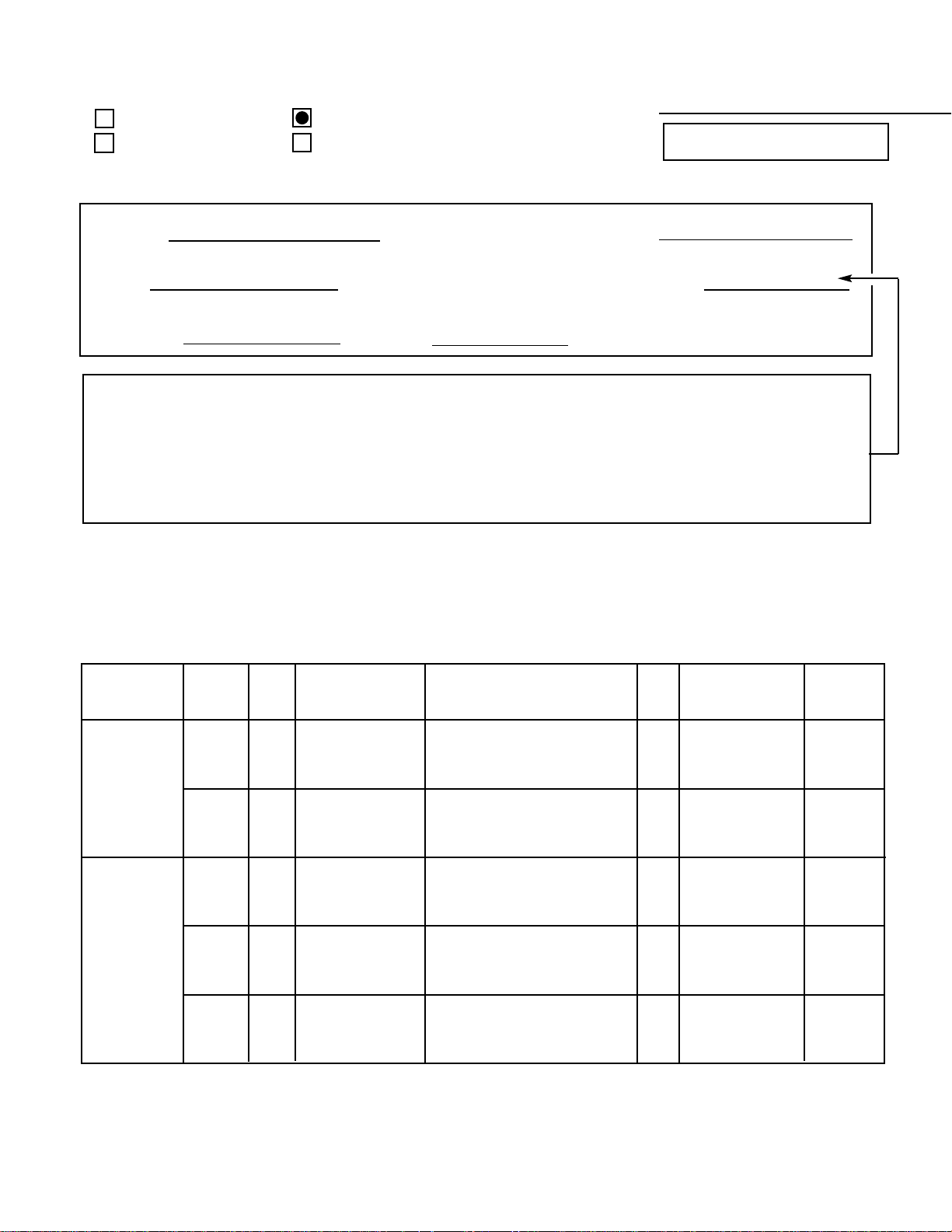
Page &
Section
Schematic
Location
Part No.
Description
Q’ty
Interchange-
ability
Reason
Page 20,
Chassis
Electrical
Parts List
Page 22
Chassis
Electrical
Parts List

May / 2005 / 2000 SMC
Printed in U.S.A.
For parts or service contact
21605 Plummer Street
Chatsworth, CA 91311 (U.S.A.)
300 Applewood Crescent,
Concord, Ontario L4K 5C7 (CANADA)
SANYO Fisher Service Corporation
Contents
Safety Instructions . . . . . . . . . . . . . . . . . . 2
Service Adjustments. . . . . . . . . . . . . 3 - 11
Service Hints. . . . . . . . . . . . . . . . . . . . . . 11
Mechanical Disassemblies. . . . . . . . . . . 12
Chassis Electrical Parts List . . . . . . 13 - 22
Cabinet Parts List . . . . . . . . . . . . . . . . . . 23
Component and Test Point
Locations . . . . . . . . . . . . . . . . . . . 24 - 27
Schematic Insert . . . . . . . . . . . . . . . 29 - 36
Schematic Notes . . . . . . . . . . . . . . . . . 29
Pin Layouts . . . . . . . . . . . . . . . . . . . . . 29
Capacitor and Resistor Codes . . . . . . 29
Block Diagram . . . . . . . . . . . . . . . 30 - 31
Voltage Charts . . . . . . . . . . . . . . . 30 - 32
Waveforms. . . . . . . . . . . . . . . . . . . . . . 32
Main Board . . . . . . . . . . . . . . . . . . 33 - 36
CRT Socket Board . . . . . . . . . . . . . . . . 33
Specifications
Power Rating . . . . . . . . . . . . . . . . . . . . . 120V, 60Hz
85W (Avg), 2.5A (Max)
Antenna Input Impedance. . . . . . . . . . . . . . . . . 75Ω
UHF/VHF/CATV
Receiving Channel . . . . . . . . . . . . . . . . 2 - 13 (VHF),
14 - 69 (UHF),
01, 14-94, 95-125 (CATV)
Remote Ready . . . . . . . . . . 24 Key Remote Control
Sound Output . . . . . . . . . . . . . . . . . . . . . . 1.0 W/CH
Intermediate Frequency
Picture IF Carrier. . . . . . . . . . . . . . . . . . 45.75MHz
Sound IF Carrier . . . . . . . . . . . . . . . . . . 41.25MHz
Color Sub Carrier . . . . . . . . . . . . . . . . . 42.17MHz
Picture Tube. . . . . . . . . . . . . . . . . . M80JUA098X72
M80JUA098X73
Semiconductors
Integrated Circuits. . . . . . . . . . . . . . . . . . . . . . . 12
Transistors. . . . . . . . . . . . . . . . . . . . . . . . . . . . . 25
Except within Tuner and RC Pre-Amp.
Cabinet Dimensions
Width. . . . . . . . . . . . . . . . . . . . . . . . . . . . . 755 mm
Height . . . . . . . . . . . . . . . . . . . . . . . . . . . . 732 mm
Depth. . . . . . . . . . . . . . . . . . . . . . . . . . . . . 538 mm
REFERENCE No. SM780102-03
DS32225, G7TVM, PRODUCT CODE 111370493
DS32225
Model:
COLOR TELEVISION
AS
FILE NO.
Notice
CORRECTION
SERVICE FLASH
PRODUCTION CHANGE
ADD INFORMATION
Please add this notice to the Service Manual listed below.
REVISION 3
Category :
U.S.A. / CANADA
Destination:
April / 15 / 2005
Date:
32225-03
Effective from : Chassis No.
SM780102
REF : No.
NOTE: Match the Chassis No. on the unit’s back cover with the Chassis No. in the Service Manual.
If the Service Manual Chassis No. does not match the unit’ s, additional Service Literature is
required. This chassis is similar to Chassis No. 32225-00, however, all Service
Information is given in this Notice for Chassis No. 32225-03 used in Model DS32225.
Servicing should be performed by only trained and qualified service personnel.
— 2 —
SAFETY PRECAUTIONS
WARNING: The chassis of this receiver has a floating
ground with the potential of one half the AC line voltage in
respect to earth ground. Service should not be attempted by
anyone not familiar with the precautions necessary when
working on this type of equipment.
The following precautions must be observed:
1. An isolation transformer must be connected in the power
line between the receiver and the AC line before any service is performed on the receiver.
2. Comply with all caution and safety-related notes provided on the side of the cabinet, inside the cabinet, on the
chassis, and the picture tube.
3. When replacing a chassis in the cabinet, always be certain
that all the protective devices are installed properly, such
as control knobs, adjustment covers, shields and barriers.
DO NOT OPERATE THIS TELEVISION RECEIVER
WITHOUT THE PROTECTIVE SHIELD IN POSITION AND
PROPERLY SECURED.
4. Before replacing the back cover of the set, thoroughly
inspect the inside of the cabinet to see that no stray parts
or tools have been left inside.
Before returning any television to the customer, the
service technician must perform the following safety
checks to be sure that the unit is completely safe to
operate without danger of electrical shock.
ANTENNA COLD CHECK
Remove AC plug from the 120 VAC outlet and place a
jumper across the two blades. Connect one lead of an ohmmeter to the jumpered AC plug, and touch the other lead to
each exposed antenna terminal (UHF and VHF antenna terminals). The resistance must measure between 1M ohm and
5.2M ohm. Any resistance value below or above this range
indicates an abnormality which requires corrective action.
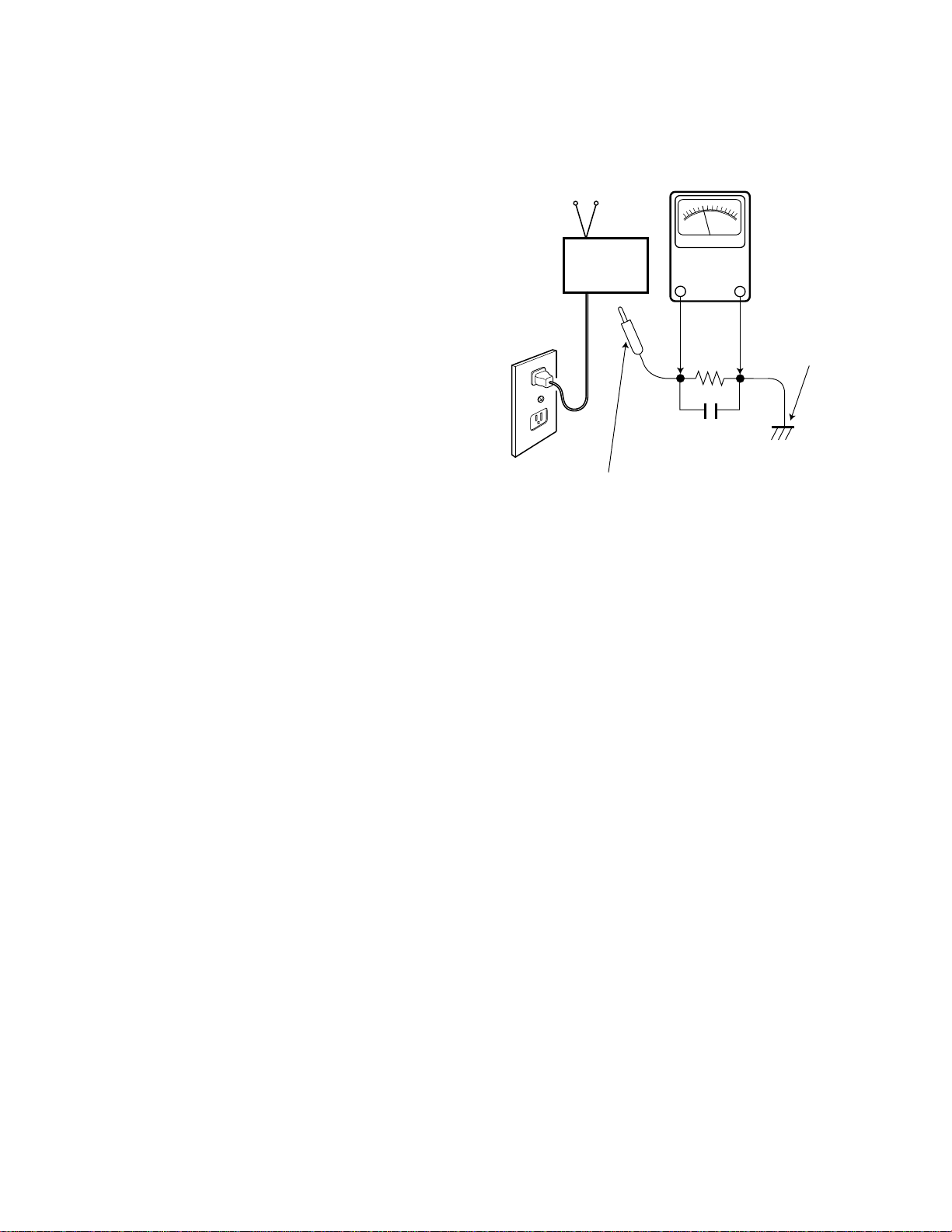
LEAKAGE CURRENT CHECK
Plug the AC line cord directly into a 120 VAC outlet. (Do not
use an isolation transformer for this check.) Use an AC voltmeter, that has 5000 ohms per volt or more sensitivity.
Connect a 1500 ohm 10 watt resistor, paralleled by a 0.15 µF
150 VAC capacitor, between a known good earth ground
(water pipe, conduit, etc.) and all exposed metal parts of the
cabinet (antennas, handle bracket, metal cabinet, screw
heads, metal overlays, control shafts, etc.). Measure the AC
voltage across the 1500 ohm resistor. The AC voltage
should not exceed 750 mV. A reading exceeding 750 mV
indicates that a dangerous potential exists. The fault must
be located and corrected. Repeat the above test with the
receiver power plug reversed.
NEVER RETURN A RECEIVER TO THE CUSTOMER
WITHOUT TAKING THE NECESSARY CORRECTIVE ACTION.
X-RADIATION PRECAUTION
The primary source of X-RADIATION in solid-state receivers is
the picture tube. The picture tube is specially constructed to
limit X-Ray emission. For continued X-RADIATION protection,
the replacement tube must be the same type as the original
(including the suffix letter in the part numbers). Excessive high
voltage may produce potentially hazardous X-RADIATION. To
avoid such hazards, the high voltage must be maintained within
specific limits. Refer to the X-RADIATION WARNING NOTE on
the CHASSIS SCHEMATIC in this service manual for specific
high voltage limits. If the high voltage exceeds specified limits,
check the components specified on the chassis schematic
diagram and take the necessary corrective action. Carefully
follow the instructions for the +B Voltage Check and the High
Voltage Check to maintain the high voltage within the specified
limits.
HIGH VOLTAGE HOLD-DOWN TEST
To prevent X-RADIATION from the picture tube due to
excessive high voltage, a HOLD-DOWN circuit is provided in
the high voltage circuit. Every time the receiver is serviced,
the high voltage HOLD-DOWN circuit must be tested for
proper operation. Refer to the HIGH VOLTAGE HOLDDOWN TEST in service adjustments.
PRODUCT SAFETY NOTICE
When replacing components in a receiver, always keep in
mind the necessary product safety precautions. Pay special
attention to the replacement of components marked with a
star (★) in the parts list and in the schematic diagrams. To
ensure safe product operation, it is necessary to replace
those components with the exact same PARTS.
SAFETY INSTRUCTIONS
READING SHOULD NOT EXCEED 750 mV.
AC VOLTMETER
(5000 ohms per volt or more sensitivity)
TELEVISION
RECEIVER
Good earth ground
such as a water pipe,
conduit, etc.
AC OUTLET
1500 ohm
10 watt
0.15 µF 150V AC
To be touched to all of exposed metal parts.
Voltmeter Hook-up for Leakage Current Check.
GENERAL
This set has an on-screen Service Menu system included in the CPU that allows remote operation for most of the service adjustments.
To enter the Service Menu, first disconnect the AC power cord. Then while pressing the MENU key on the front control panel, reconnect the AC power cord. The adjustments can now be made with the remote control or front control panel keys.
ON-SCREEN SERVICE MENU SYSTEM
1. Enter the Service Menu:
•While pressing the MENU key on the front control panel, reconnect the
AC power cord. The Service Menu Display will now appear. See Figure 1.
2. Service Adjustments:
•Press the ▲ or ▼ key to select the desired service menu item you
want to adjust. (See page 5 for On-screen Service Menu.)
•Use the + or – key or number keys to adjust the data.
The + or – keys will increase or decrease the data sequentially.
The number keys (0 ~ 7) toggle only their respective bits between
1 and 0 and are used to change the Sub-Address. For example to
change bit 5 press the number 5 key. See below.
3. Exit from the Service Menu:
•Press the MENU key to turn off the Service Menu display.
SERVICE ADJUSTMENTS
— 3 —
IC802 (EEPROM) REPLACEMENT
When IC802 (EEPROM) is replaced, IC801 (CPU) will automatically write the initial reference data into IC802 for basic TV operation.
However, the bus data should be checked and some bus data should be set up before attempting the service adjustments.
(See pages 5 – 7, Table 1, for detailed bus data information.)
INITIAL BUS DATA SETUP
Note: When IC802 (EEPROM) is replaced, change the following initial reference data for proper TV operation before
attempting service adjustments.
1. Disconnect the AC power cord (AC 120V line).
2. While pressing the MENU key, reconnect the AC power cord. The Service Menu display will now appear.
3. Select NO. 3B SCN (Sub Contrast) with ▲ or ▼ key. Adjust the data with + or – key for 2B.
4. Select NO. 3C SCO (Sub Color) with ▲ or ▼ key. Adjust the data with + or – key for 08.
5. Select NO. 3D STI (Sub Tint) with ▲ or ▼ key. Adjust the data with + or – key for 1C.
6. Select NO. 3E SB (Sub Bright) with ▲ or ▼ key. Adjust the data with + or – key for 15.
7. Select NO. 51 VS (V Size) with ▲ or ▼ key. Adjust the data with + or – key for 1D.
8. Select NO. 54 BLK7SSL3 (Blk Str Dis / Blk Str Cha / S Slice Dn2 / S Slice Dn1) with ▲or ▼ key. Adjust the data with num-
ber keys for A0.
9. Select NO. 55 AFC7OSD5OM3BSG2CA1 (AFC G Up / AFC G Dn / OSD Level / OSD / OM Det) with ▲ or ▼ key. Adjust the
data with number keys for 84.
10. Select NO.56 VSD7ASD6HP4 (V Sync Det / Auto Slice Dn / FBP Vth L / H Phase) with ▲ or ▼ key. Adjust the data with
number keys for 07.
11. Select NO. 68 S4G7STR6CRP3 (SIF4.5 Gain Dn / S Trap Fine LSB / Cr Ped Adj ) with ▲ or ▼ key. Adjust the data with
number keys for 8B.
12. Select NO. 69 CBCR7CBP3 (CbCr Pedestal On / CbCr Gain Up / Cb pedestal Fine Adj) with ▲ or ▼ key. Adjust the data
with number keys for CC.
3C SCO
15 00010101
Figure 1. Service Menu Display
ITEM NO.
TITLE
BINARY DATA
(8 bit)
HEX DATA
(b7) (b6) (b5) (b4) (b3) (b2) (b1) (b0)
0 1 0 1 0 1 1 0
BINARY DATA
(8 bit)

— 4 —
INITIAL BUS DATA SETUP (Cont.)
13. Select NO. 6B PCW (Picture Width) with ▲ or ▼ key. Adjust the data with number keys for 28.
14. Select NO. 6C PAR (E-W Parabola) with ▲ or ▼ key. Adjust the data with number keys for 26.
15. Select NO. 6D COR (E-W Corner) with ▲ or ▼ key. Adjust the data with number keys for 14.
16. Select NO. 6E TRA (Trapezium) with ▲ or ▼ key. Adjust the data with number keys for 3B.
17 Select NO. 85 HR (OSD H-Position) with ▲ or ▼ key. Adjust the data with number keys for 15.
18. Select NO. 86 SBO (Sub Bright Offset) with ▲ or ▼ key. Adjust the data with number keys for 16.
19. Select NO.8A DCL (YUV Color Offset) with ▲or ▼ key. Adjust the data with number keys for 0D.
20. Select NO. 8B DTN (YUV Tint Offset) with ▲ or ▼ key. Adjust the data with number keys for F3.
21. Select NO. 8D ECN (16:9 Contrast Offset) with ▲ or ▼ key. Adjust the data with number keys for EA.
22. Select NO. 91 EVS (16:9 V Size Offset) with ▲ or ▼ key. Adjust the data with number keys for F3.
23. Select NO. 92 EVP (16:9 V Position Offset) with ▲ or ▼ key. Adjust the data with number keys for 04.
24. Select NO. 9C VA2 (AV Mode AFC1 Gain Up 2) with ▲ or ▼ key. Adjust the data with number keys for 00.
25. Select NO. 9E RYT (RF Y Delay Time Adj) with ▲ or ▼ key. Adjust the data with number keys for 02.
26. Select NO. A0 SYT (S In Y Delay Time Adj) with ▲ or ▼ key. Adjust the data with number keys for 03.
27. Select NO. A4 VKL (V Kill At Power Off) with ▲ or ▼ key. Adjust the data with number keys for 0F.
28. Press the MENU key to turn off the Service Menu display.
SERVICE ADJUSTMENTS (Cont.)
No. TITLE
INITIAL REFERENCE INITIAL SETUP INITIAL SETUP
FUNCTION
DATA HEX DATA HEX DATA BINARY
3B SCN 20 2B* 00101011 Sub Contrast (5~0)
3C SCO 0F 08* 00001000 Sub Color (4~0)
3D STI 0F 1C* 00011100 Sub Tint (4~0)
3E SB 05 15* 00010101 Sub Bright (5~0)
3F SSH 1A 1A 00011010 Sub Sharpness (4~0)
40 RFAGC 2F 2F 00101111 RF AGC (6~0)
41 VCO5 1D 1D 00011101 VIF VCO Adj (5~0)
42 EXT6CL5TS3BS1T0 29 29 00101001 V Mute (7) A Ext (6) C Clip (5) C Trap (4) Video T (3) ABCL (2)
43 AT 00 00 00000000 Audio ATT (6~0)
44 SHP5 00 00 00000000 ABCL Gain (7) AFT Defeat (6) Video Tone (5~0)
45 CNT6 00 00 00000000 EXE RGBC Clip Off (7) Contrast (6~0)
46 VG7DLF2DLT2 83 83 10000011 V Gain (7~5) Y/C (4) EXT (3) Y DL Fine Adj (2) Y DL T Adj (1~0)
47 VDE7TNT6 00 00 00000000 VIF Defeat (7) Tint (6~0)
48 CLR6 00 00 00000000 Blue Back (7) Color (6~0)
49 HVBL7 00 00 00000000 HV BLK Off (7)
4A BRT7 00 00 00000000 Bright (7~0)
4B RD6 40 40 01000000 Force Mono (7) Drive R (6~0)
4C BD6 40 40 01000000 Drive B (6~0)
4D RB 00 00 00000000 Bias R (7~0)
4E GB 00 00 00000000 Bias G (7~0)
4F BB 00 00 00000000 Bias B (7~0)
50 HVCO2 1C 1C 00011100 White Back (7) H VCO Adj (2~0)
51 VS5 19 1D* 00011101 V Size (5~0)
52 MON7GA3CTRF2 0E 0E 00001110 Monitoring (7~4) Gamma Control (3~2) C Trap Fine Adj (1~0)
53 VW6YSW5VSHT2 10 10 00010000 H-Free (7) V 1Win (6) Ysw LPF (5) H St (4) Serv Sw V Sh (2~0)
54 BLK7SSL3 D0 A0* 10100000 Blk Str Dis (7~6) Blk Str Cha (5~5) S Sli Dn2 (3) S Sli Dn 1
55 AFC7OSD5OM3BSG2CA1
80 84* 10000100 AFC G Up (7) AFC G Dn (6) OSD Level (5) OSD (4) OM Det (3)
56 VSD7ASD6HP4 0A 07* 00000111 V Sync Det (7) Auto Slice Dn (6) FBP Vth L (5) H Phase (4~0)
57 BSTNT6 00 00 00000000 YCbCr Sw (7) Baseband Tint (6~0)
58 RSV18 20 20 00100000 Not Used)
59 RSV19 20 20 00100000 Not Used)
5A RSV1A 20 20 00100000 Not Used)
5B RSV1B 20 20 00100000 Not Used)
5C VSC5 B3 B3 10110011 V S-Correction (5~0)
5D VAGC6VL5 57 57 01010111 V AGC (6) V Linearity (5~0)
5E STRP7 00 00 00000000 S-Trap Off (7)
5F STFA7 90 90 10010000 S-Trap Fine Adj (7~5)
60 STF7FHT6 00 00 00000000 S-Trap Fine Adj MSB (7) Force H Tone (6)
61 VSD7CR3CB1 00 00 00000000 CrDL Fine Adj (3~2) CbDL Fine Adj (1~0)
62 VBLK7AFCGU6 40 40 01000000 V Blk Half (7) AFC2 Gain Up (6)
63 RMU7RMC6CTI3 08 08 00001000 R MTX Up (7) R MTX Dn (6) CTI (3)
64 SSDN6 40 40 01000000 S Slice Down 3 (6)
65 STS3FC0 00 00 00000000 S-Trap Self2 (3) S-Trap Self1 (2) S-Trap Test (1) Force Color (0)
66 AFCGU7 80 80 10000000 AFC1 Gain Up2 (7)
67 AFCIF6VSD3IFAM1 48 48 01001000 AFC1 IF Cont (6) V Sync Det2 (3) IF AGC Mode (1)
68 S4G7STR6CRP3 88 8B* 10001011 SIF4.5 Gain Dn (7) S Trap Fine LSB (6) Cr Ped Fine Adj (3~0)
69 CBCR7CBP3 08 CC* 11001100 CbCr Ped On (7) CbCr Gain Up (6) Cb Ped Fine Adj (3~0)
6A SIF7VT5AMF432 20 20 00100000 SIF PAL INV (7) SIF PAL (6) VTH HYS Off (5) AMF CUR Dn (4)
6B PCW 20 28* 00101000 Picture Width (5~0)
— 5 —
Table 1. ON-SCREEN SERVICE MENU
When IC802 (EEPROM) is replaced, check the bus data to confirm they are the same as below. The shaded menu should be
checked and be set up or readjusted according to the procedures described in the following pages. Initial Setup Data marked
with an * should be changed from Initial Reference Data. (See pages 3 and 4 for Initial Bus Data Setup.)
— 6 —
Table 1. ON-SCREEN SERVICE MENU (Continued)
SERVICE ADJUSTMENTS (Cont.)
No. TITLE
INITIAL REFERENCE INITIAL SETUP INITIAL SETUP
FUNCTION
DATA HEX DATA HEX DATA BINARY
6C PAR 23 26* 00100110 E-W Parabola (5~0)
6D COR 10 14* 00010100 E-W Corner (4~0)
6E TRA 40 3B* 00111011 Trapezium (6~0)
6F HCC 03 03 00000011 H-Comp (6~4) H-Cent DAC (2~0)
80 ATT 07 07 00000111 Attenuation -MTS Input Level (3~0)
81 WDB 20 20 00100000 Wide Band - Low Separation (5~0)
82 SPC 20 20 00100000 Spectral - High Separation (5~0)
83 OPT E4 E4 11100100 Surround (7) E/W (6) Aspect Ratio (5) VIDEO (2)
84 OP2 20 20 00100000 Game (7) Component (5) V Guide(0)
85 HR 1A 15* 00010101 OSD H-Position (6~0)
86 SBO 00 16* 00010110 Sub Bright Offset (7~0)
87 RFT 00 00 00000000 RF Tint Offset (7~0)
88 DCN 00 00 00000000 YUV Contrast Offset (7~0)
89 DBR 00 00 00000000 YUV Bright Offset (7~0)
8A DCL F8 0D* 00001101 YUV Color Offset (7~0)
8B DTN 00 F3* 11110011 YUV Tint Offset (7~0)
8C DSH FE FE 11111110 YUV Sharpness Offset (7~0)
8D ECN E0 EA* 11101010 16:9 Contrast Offset(7~0)
8E EBR 00 00 00000000 16:9 Bright Offset(7~0)
8F ECL 00 00 00000000 16:9 Color Offset(7~0)
90 ETN 00 00 00000000 16:9 Tint Offset(7~0)
91 EVS D4 F3* 11110011 16:9 V Size Offset(7~0)
92 EVP 00 04* 00000100 16:9 V Position Offset (7~0)
93 ESC 00 00 00000000 16:9 V S Correction Offset (7~0)
94 EUV 00 00 00000000 16:9 V Linearity Offset (7~0)
95 EBO 00 00 00000000 16:9 HV BLK Off (7)
96 EBH 00 00 00000000 16:9 HV BLK Half (7)
97 EWP F1 F1 11110001 16:9 E-W Parabola Offset (7~0)
98 EWC FF FF 11111111 16:9 E-W Corner Offset (7~0)
99 ETR 09 09 00001001 16:9 Trapezium Offset (7~0)
9A SBI 20 20 00100000 Sub Bias (5~0)
9B VA1 01 01 00000000 AV Mode AFC1 Gain Up 1 (7)
9C VA2 01 00* 00000001 AV Mode AFC1 Gain Up 2 (7)
9D PWT 01 01 00000001 White Back (3~0)
9E RYT 01 02* 00000010 RF Y Delay Time Adj (1~0)
9F RYF 01 01 00000001 RF Y Delay Time Fine Adj (2)
A0 SYT 02 03* 00000011 S In Y Delay Time Adj (1~0)
A1 SYF 00 00 00000000 S In Y Delay Time Fine Adj (2)
A2 DYT 01 01 00000001 YUV Y Delay Time Adj (1~0)
A3 DYF 01 01 00000001 YUV Y Delay Time Fine Adj (2)
A4 VKL 0A 0F* 00001111 V Kill At Power Off (3~0)
A5 RFC 00 00 00000000 RF Color Offset (7~0)
A6 RFS 05 05 00000101 RF Sharpness Offset (7~0)
A7 EPW FE FE 11111110 16:9 Picture Width Offset (7~0)
A8 DRV
R40 R40 01000000 Red Drive Adjustment (See Note 1.)
R40 R40 01000000 Blue Drive Adjustment (See Note 1.)
– - - - Red Bias Adjustment (See Note 2.)
– - - - Green Bias Adjustment (See Note 2.)
– - - Blue Bias Adjustment (See Note 2.)
— 7 —
PROGRAM CODES
The microprossesor used in this model is a multi-purpose
type and is used in several different models. To ensure
proper operation and the correct features for your particular model, the program codes must be correct.
Note 1. Option Data 1 (NO. 83 OPT) should be hexadecimal
E4 (11100100 binary). See page 4 INITIAL DATA SETUP for
set up procedure. If this program code is wrong the TV will
not operate properly.
Note 2. Option Data 2 (NO. 84 OP2) should be hexadecimal
20 (00100000 binary). See page 4 INITIAL DATA SETUP for
set up procedure. If this program code is wrong the TV will
not operate properly.
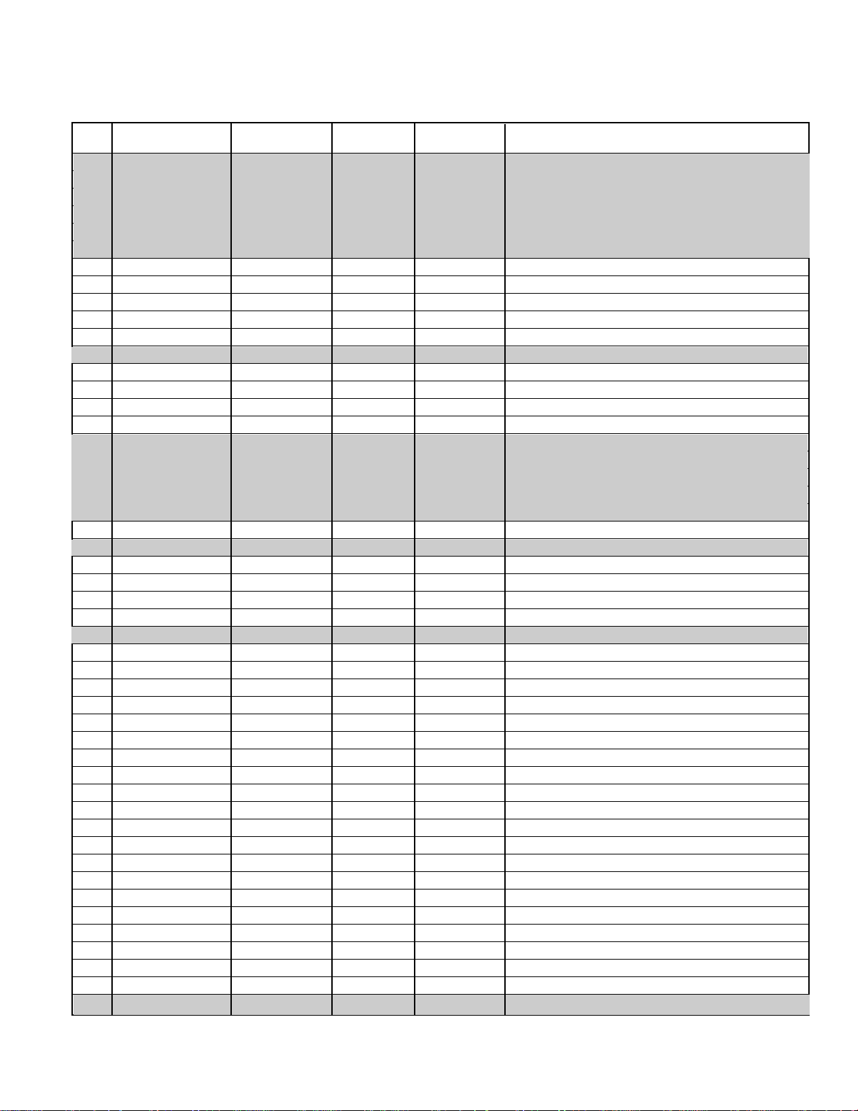
Note 1.
Red/Blue Drive Adjustments in Service Menu NO. A8 DRV:
Adjust Red and Blue Drive Levels alternately with 1, 3, 7,
and 9 keys on the remote control. See Figure 2. The Drive
Level adjustment data will be written in the Service Menu
No. 4B RD and 4C BD automatically.
1
2
3
4 5 6
7 98
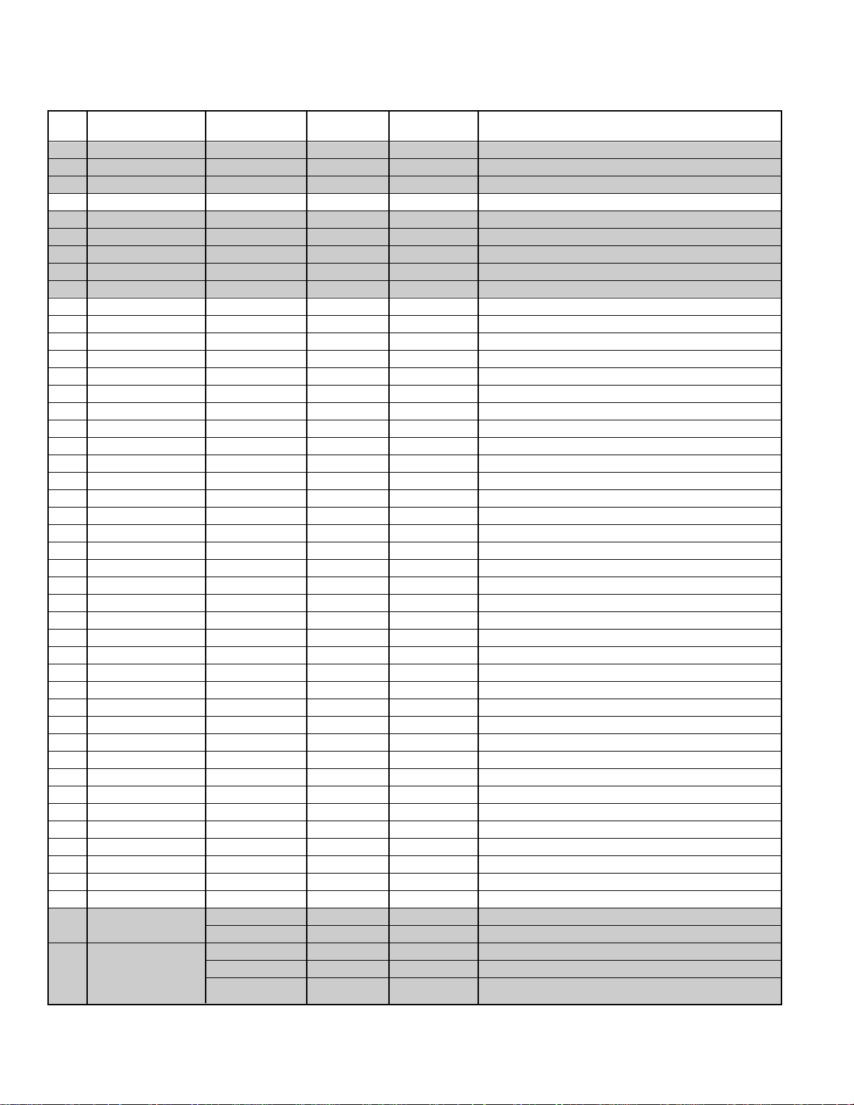
RB(–)
RB(+)
BB(–)
BB(+)
(N/A)
GB(–)
(N/A)
GB(+)
(N/A)
FOR RED BIAS ADJUSTMENT
FOR BLUE BIAS ADJUSTMENT
FOR GREEN BIAS ADJUSTMENT
Figure 2.
Figure 3.
1
2
3
4 5 6
7 98
RD(–)
RD(+)
BD(–)
BD(+)
(N/A)
(N/A)
(N/A)
(N/A)
(N/A)
FOR RED DRIVE ADJUSTMENT
FOR BLUE DRIVE ADJUSTMENT
Note 2.
Red/Green/Blue Bias Adjustments in Service Menu
A9 (No Vertical Sweep):
Adjust each Bias Level with 1, 3, 4, 6, 7, or 9 key on the
remote control. See Figure 3. The Bias Level adjustment
data will be written in the Service Menu No. 4D RB,
No. 4E GB, and No. 4F BB automatically.
DRIVE AND BIAS ADJUSTMENTS
BIT FUNCTION
DATA
01
0 ~ 1 TV / HOTEL / MON N/A N/A
2 VIDEO MODE NONE YES
3 ~ 4 CLOCK N/A N/A
5 ASPECT RATIO NONE YES
6 NOT USED — —
7 SURROUND NONE YES
BIT FUNCTION
DATA
01
0 V-GUIDE NONE YES
1 COLOR ENHANCER N/A N/A
2 INITIAL CH & XDS N/A N/A
3 NOT USED — —
4 PIP N/A N/A
5 COMPONENT NONE YES
6 BASS & TREBLE / TONE N/A N/A
7 GAME N/A N/A
— 8 —
ANTENNA CONNECTIONS
This receiver is designed for UHF/VHF reception. A 75 ohm
terminal is provided for UHF and VHF receptions. When
connecting a CATV antenna system, connect the 75 ohm
coaxial cable directly to the 75 ohm terminal. For 300 ohm
VHF antenna, use an adapter (not included with the TV set).
CIRCUIT PROTECTION
Fuse F601 (4A) is included in the AC line. This fuse must be
replaced with the proper fuse (see Parts List).
+B VOLTAGE CHECK
Connect Voltmeter + lead to TJ1 130V and – lead to ground
(TE7). Connect receiver to AC 120V line. Tune receiver to an
active channel. Reset the picture controls to the FACTORY
PRESET levels (press remote control RESET key twice).
Voltage must measure between +128.0V and +132.0V. If the
voltage is out of this range, the power circuit must be
checked. No +B adjustment is provided on this chassis.
HORIZONTAL CENTERING ADJUSTMENT
1. Tune receiver to an active channel.
2. Check that picture is in the horizontal center of TV screen.
If picture is not centered horizontally, perform steps 3 ~ 6.
3. Turn off the receiver and disconnect the AC power cord.
4. While pressing the MENU key, reconnect the AC power
cord. The Service Menu display will now appear.
5. Select NO. 56 VSD7ASD6HP4 (Horizontal Phase) with
▲ or ▼ key.
6. Adjust the data with + or – key for horizontal center. To
turn off the Service Menu display, press the MENU key.
HORIZONTAL WIDTH ADJUSTMENT
1. Tune receiver to an active channel.
2. Check the picture for proper width. If width is not correct, perform steps 3 - 6.
3. Turn off the receiver and disconnect the AC power cord.
4. While pressing the VOLUME – key, reconnect the AC
power cord. The Service Menu display will now appear.
5. Select NO. 6B PCW (Picture Width) with ▲ or ▼ key.
6. Adjust the data with numeric keys 5~2 for proper width.
To turn off the Service Menu display, press the MENU
key.
VERTICAL SIZE ADJUSTMENT
1. Tune receiver to an active channel.
2. Check the vertical size of the picture. If the vertical size is
too large or small, perform steps 3 ~ 6.
3. Turn off the receiver and disconnect the AC power cord.
4. While pressing the MENU key, reconnect the AC power
cord. The Service Menu display will now appear.
5. Select NO. 51 VS5 (Vertical Size) with ▲ or ▼ key.
6. Adjust the data with + or – key for full scan. To turn off
the Service Menu display, press the MENU key.
VERTICAL CENTERING ADJUSTMENT
1. Tune receiver to an active channel.
2. C he ck that picture is in the center of TV screen. If picture
center is too low, add resistor R513 (470 ohm 1W) and J520.
If picture center is too high, add resistor R513 (470 ohm 1W)
and J530.
RF AGC ADJUSTMENT
1. Tune receiver to strongest VHF station in your area.
2. Set contrast and brightness controls for maximum.
3. Turn off the receiver and disconnect the AC power cord
(120V AC line).
4. While pressing the MENU key, reconnect the AC power
cord. The Service Menu display will now appear.
5. Select NO. 40 RFAGC (RF AGC Delay) with ▲ or ▼ key.
6. Adjust the data with + or – key in the direction which
causes snow to appear; then in the opposite direction
until the snow just disappears.
7. To turn off the Service Menu display, press the MENU key.
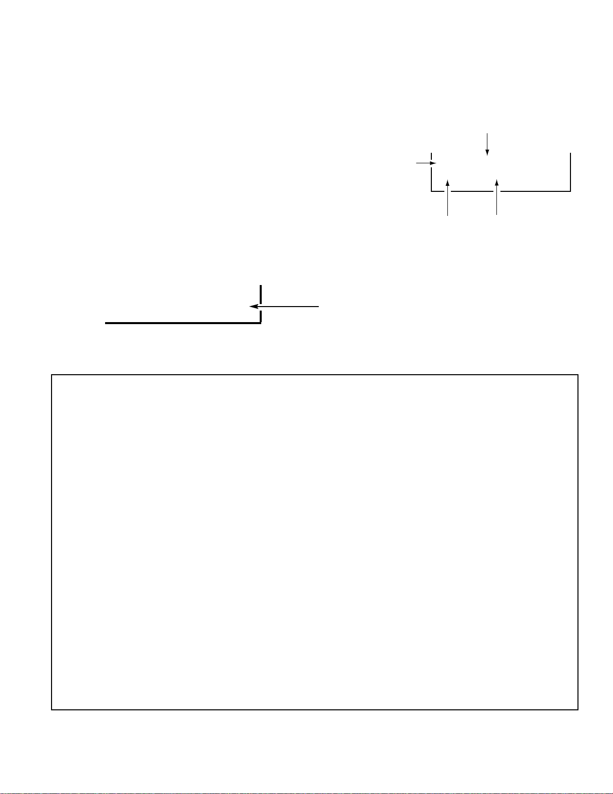
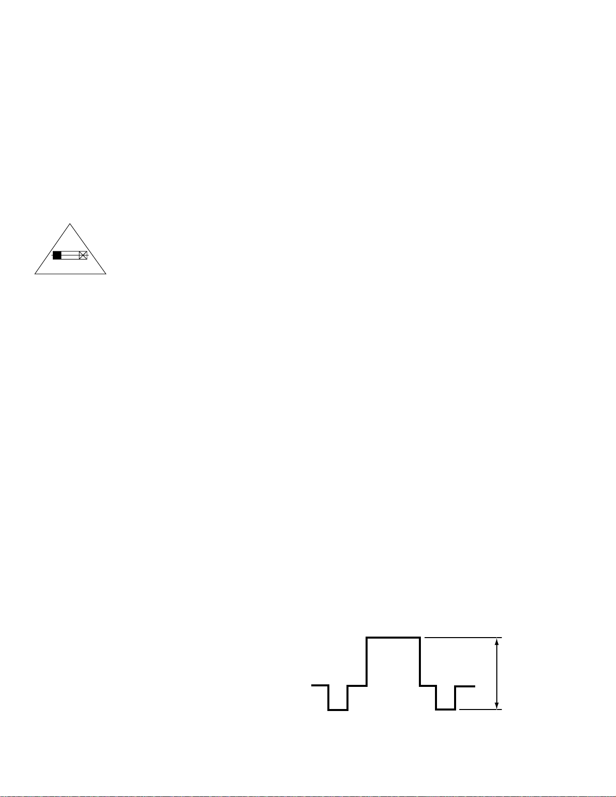
VIDEO LEVEL
1. Connect color-bar generator to antenna terminals.
2. Turn off the receiver and disconnect the AC power cord
(AC 120V line).
3. Connect oscilloscope to TP16 (Q131 emitter) and ground.
4. While pressing the Menu key, reconnect the AC power
cord. The Service Menu will now appear.
5. Select NO. 46 VG7DLF2DLT2 (Video Gain 7~5) with the
▲ or ▼ key.
6. Adjust with the number keys (7~5) for an oscilloscope
reading of 1.0 ± 0.1 VP-P at TP16. Press the MENU key to
turn off the Service Menu display.
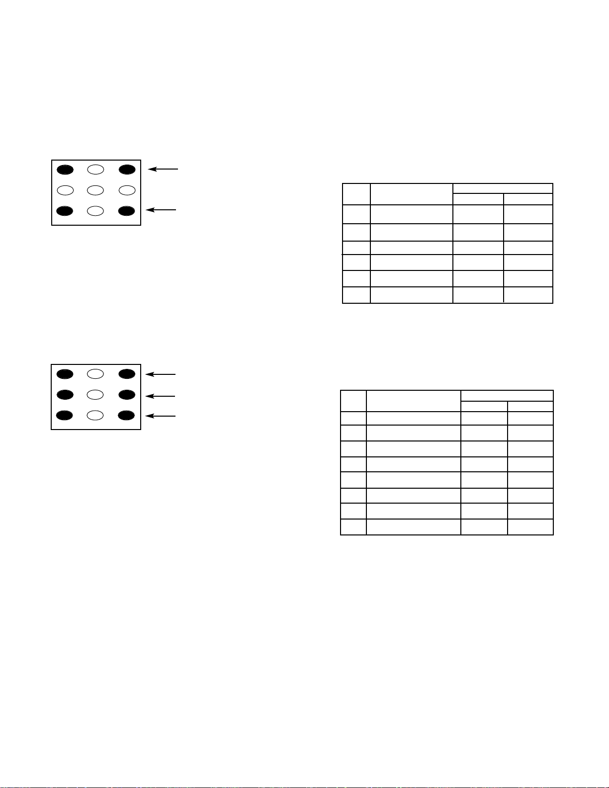
CAUTION
FOR CONTINUED PROTECTION AGAINST
A RISK OF FIRE, REPLACE ONLY WITH THE
SAME TYPE 4A, 125V FUSE.
ATTENTION : POUR MAINTENIR LA PROTECTION CONTRE LES RISQUES
D’ INCENDIE UTILISER UN FUSIBLE DE
RECHANGE DE MEME TYPE 4A, 125V.
1.0 ± 0.1 VP-P
Figure 4.
SERVICE ADJUSTMENTS (Continued)
4A 125V
— 9 —
GRAYSCALE ADJUSTMENT
1. Set the picture controls to the Auto levels or Reset (use
MENU key and ▲ or ▼ key or RESET key).
2. Turn off the receiver and disconnect the AC power cord
(120V AC line).
3. While pressing the MENU key, reconnect the AC power
cord. The Service Menu display will now appear.
4. Select NO. 4D RB (Red Bias), NO. 4E GB (Green Bias),
and NO. 4F BB (Blue Bias) with ▲ or ▼ key and set each
data to 0 with + or – key.
5. Select NO. 4B RD (Red Drive) and NO. 4C BD (Blue Drive)
with ▲ or ▼ key and set each data to 40 with + or – key.
6. Set NO. 3B SCN (Sub Contrast) data to 20, NO. 3C SCO
(Sub Color) data to 05, NO. 3D STI (Sub Tint) to 11, NO. 3E
SB (Sub-Brightness) data to 1A, and NO. 3F SSH (Sub
Sharpness) data to 1A with ▲ or ▼,and + or – keys.
7. Turn Screen Control (T402) to minimum (fully counterclockwise).
8. Select the Service Menu NO. AB (No Vertical Sweep)
with ▲ or ▼ key.
9. Advance Screen Control (T402) clockwise to obtain just
visible one color line. If line does not appear, place this
control to maximum (fully clockwise).
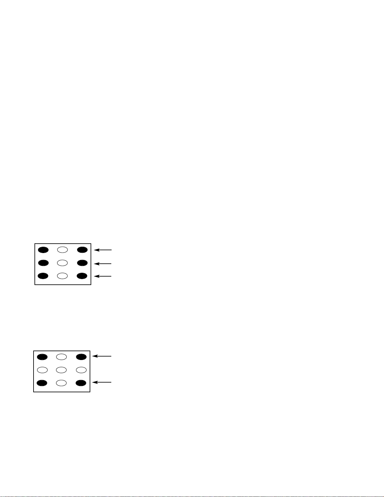
10. Raise each Bias Level with 3, 6, and 9 keys to obtain just
visible white line. See Figure 5.
11. Select the Service Menu NO. AA DRV (Drive Adjustments)
with ▲ or ▼ key.
12. Adjust Red and Blue Drive Levels alternately with 1, 3,
7, or 9 key to produce normal black and white picture in
highlight areas. See Figure 6.
13. Check for proper grayscale at all brightness levels.
To turn off the Service Menu display, press the MENU key.
Note: If Grayscale Adjustment is made after picture tube
replacement, check Brightness Level Adjustment.
FOCUS ADJUSTMENT
Adjust focus control (T402) for well defined scanning lines.
HIGH VOLTAGE CHECK
Note: +B (+130V) Voltage Check and Grayscale Adjustment
must be completed before attempting high voltage
Check.
1. Connect high voltage voltmeter – lead to ground, and
connect + lead to anode of picture tube.
2. Tune receiver to an active channel and confirm TV is
operating properly.
3. Eliminate the beam current by adjusting the contrast
and brightness controls to minimum.
4. Confirm high voltage is within 28.0 KV and 32.0 KV. If
reading is not within range, check horizontal circuit.
No high voltage adjustment is provided on this chassis.
BRIGHTNESS LEVEL ADJUSTMENT
Note: Grayscale, RF AGC, Video Level, and High Voltage Check
must be adjusted before attempting Brightness Level
Adjustment.
1. Connect a color-bar generator to the antenna terminals.
2. Switch the generator to the crosshatch pattern.
3. Reset the picture controls to the Auto levels.
4. Connect voltmeter (high impedance) + lead to terminal
TP51 and – lead to terminal TP50 on main board. Set
voltmeter for 1.5V ~ 3V range.
5. Turn off the receiver and disconnect the AC power cord.
6. While pressing the MENU key, reconnect the AC power
cord. The Service Menu display will now appear.
7. Select NO. 3E SB (Sub Brightness) with ▲ or ▼ key.
8. Adjust the data with + or – key for 680mVDC.
9. Press the MENU key to turn off the Service Menu display.
10. Check brightness level on every active channel, readjust
(repeat steps 5 ~ 9), if necessary.
Note: Do not set to excessive brightness level, otherwise
the contrast level will be suppressed.
1
2
3
4 5 6
7 98
RB(–)
RB(+)
BB(–)
BB(+)
(N/A)
GB(–)
(N/A)
GB(+)
(N/A)
Figure 5. Remote Control Number keys’ functions in
Service Menu NO. AB (No Vertical Sweep)
1
2
3
4 5 6
7 98
RD(–)
RD(+)
BD(–)
BD(+)
(N/A)
(N/A)
(N/A)
(N/A)
(N/A)
Figure 6. Remote Control Number keys’ functions in
Service Menu NO. AA DRV
FOR RED DRIVE ADJUSTMENT
FOR BLUE DRIVE ADJUSTMENT
FOR GREEN BIAS ADJUSTMENT
FOR RED BIAS ADJUSTMENT
FOR BLUE BIAS ADJUSTMENT
 Loading...