

Sanyo DS27910 Schematic
AS
FILE NO.
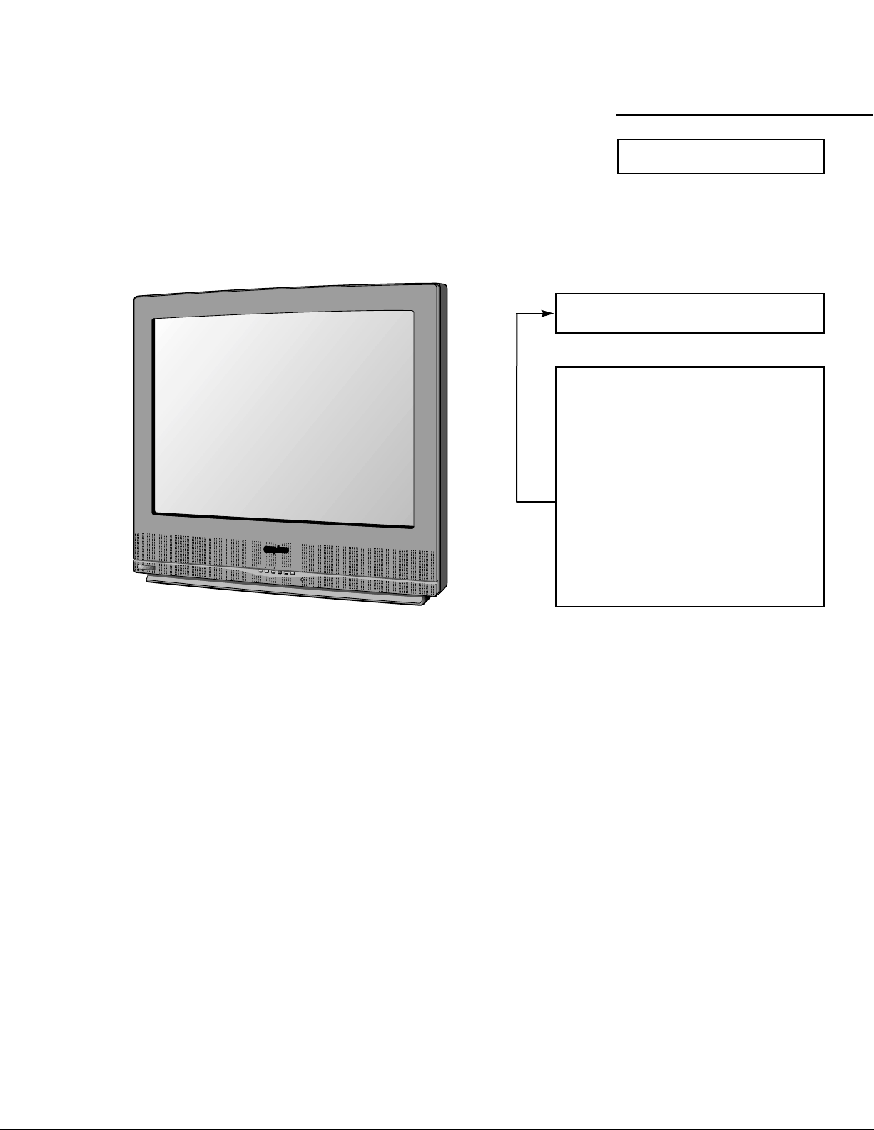
SERVICE MANUAL Remote Control Color
Television
DS27910 (U.S.A.)
ORIGINAL VERSION
Chassis No. 27910-00
NOTE: Match the Chassis No. on
the unit’s back cover with
the Chassis No. in the
Service Manual.
If the Original Version
Service Manual Chassis
No. does not match the
unit’s, additional Service
Literature is required. You
must refer to “Notices” to the
Original Service Manual
prior to servicing the unit.
Contents
Safety Instructions . . . . . . . . . . . . . . . . . . 2
Service Adjustments. . . . . . . . . . . . . 3 - 10
Service Hints. . . . . . . . . . . . . . . . . . . . . . 10
Mechanical Disassemblies. . . . . . . . . . . 11
Chassis Electrical Parts List . . . . . . 12 - 22
Cabinet Parts List . . . . . . . . . . . . . . . . . . 23
Component and Test Point
Locations . . . . . . . . . . . . . . . . . . . 24 - 27
Schematic Insert . . . . . . . . . . . . . . . 29 - 36
Schematic Notes . . . . . . . . . . . . . . . . . 29
Pin Layouts . . . . . . . . . . . . . . . . . . . . . 25
Capacitor and Resistor Codes . . . . . . 29
Block Diagram. . . . . . . . . . . . . . . 30 - 31
Voltage Charts . . . . . . . . . . . . . . . 30 - 32
Waveforms. . . . . . . . . . . . . . . . . . . . . . 32
Schematic Diagrams . . . . . . . . . . 33 - 36
Specifications
Power Rating . . . . . . . . . . . . . . . . . . . . . 120V, 60Hz
112W (Avg), 2.5A (Max)
Antenna Input Impedance . . . . . . . . . . . . . . . . 75W
UHF/VHF/CATV
Receiving Channel . . . . . . . . . . . . . . . . 2 - 13 (VHF),
14 - 69 (UHF),
01, 14-94, 95-125 (CATV)
Remote Ready . . . . . . . . . . 38 Key Remote Control
Sound Output . . . . . . . . . . . . . . . . . . . . . . 3.0 W/CH
Intermediate Frequency
Picture IF Carrier. . . . . . . . . . . . . . . . . . 45.75MHz
Sound IF Carrier . . . . . . . . . . . . . . . . . . 41.25MHz
Color Sub Carrier . . . . . . . . . . . . . . . . . 42.17MHz
Picture Tube . . . . . . . . . . . . . . . . . . A68ERF031X013
Semiconductors
Integrated Circuits. . . . . . . . . . . . . . . . . . . . . . . 12
Transistors. . . . . . . . . . . . . . . . . . . . . . . . . . . . . 45
Except within Tuner and RC Pre-Amp.
Cabinet Dimensions
Width. . . . . . . . . . . . . . . . . . . . . . . . . . . . . 664mm
Height . . . . . . . . . . . . . . . . . . . . . . . . . . . . 629mm
Depth. . . . . . . . . . . . . . . . . . . . . . . . . . . . . 487mm
REFERENCE No. SM780074
DS27910,G7YAM, PRODUCT CODE 111357080
_
A
S
MENU
CH
CH
VOL
VOL
+
PO
W
ER
— 2 —
SAFETY PRECAUTIONS
WARNING: The chassis of this receiver has a floating
ground with the potential of one half the AC line voltage in
respect to earth ground. Service should not be attempted by
anyone not familiar with the precautions necessary when
working on this type of equipment.
The following precautions must be observed:
1. An isolation transformer must be connected in the power
line between the receiver and the AC line before any service is performed on the receiver.
2. Comply with all caution and safety-related notes provided
on the side of the cabinet, inside the cabinet, on the chassis, and the picture tube.
3. When replacing a chassis in the cabinet, always be certain
that all the protective devices are installed properly, such
as control knobs, adjustment covers, shields and barriers.
DO NOT OPERATE THIS TELEVISION RECEIVER
WITHOUT THE PROTECTIVE SHIELD IN POSITION AND
PROPERLY SECURED.
4. Before replacing the back cover of the set, thoroughly
inspect the inside of the cabinet to see that no stray parts
or tools have been left inside.
Before returning any television to the customer, the
service technician must perform the following safety
checks to be sure that the unit is completely safe to
operate without danger of electrical shock.
ANTENNA COLD CHECK
Remove AC plug from the 120 VAC outlet and place a
jumper across the two blades. Connect one lead of an ohmmeter to the jumpered AC plug, and touch the other lead to
each exposed antenna terminal (UHF and VHF antenna terminals). The resistance must measure between 1M ohm and
5.2M ohm. Any resistance value below or above this range
indicates an abnormality which requires corrective action.
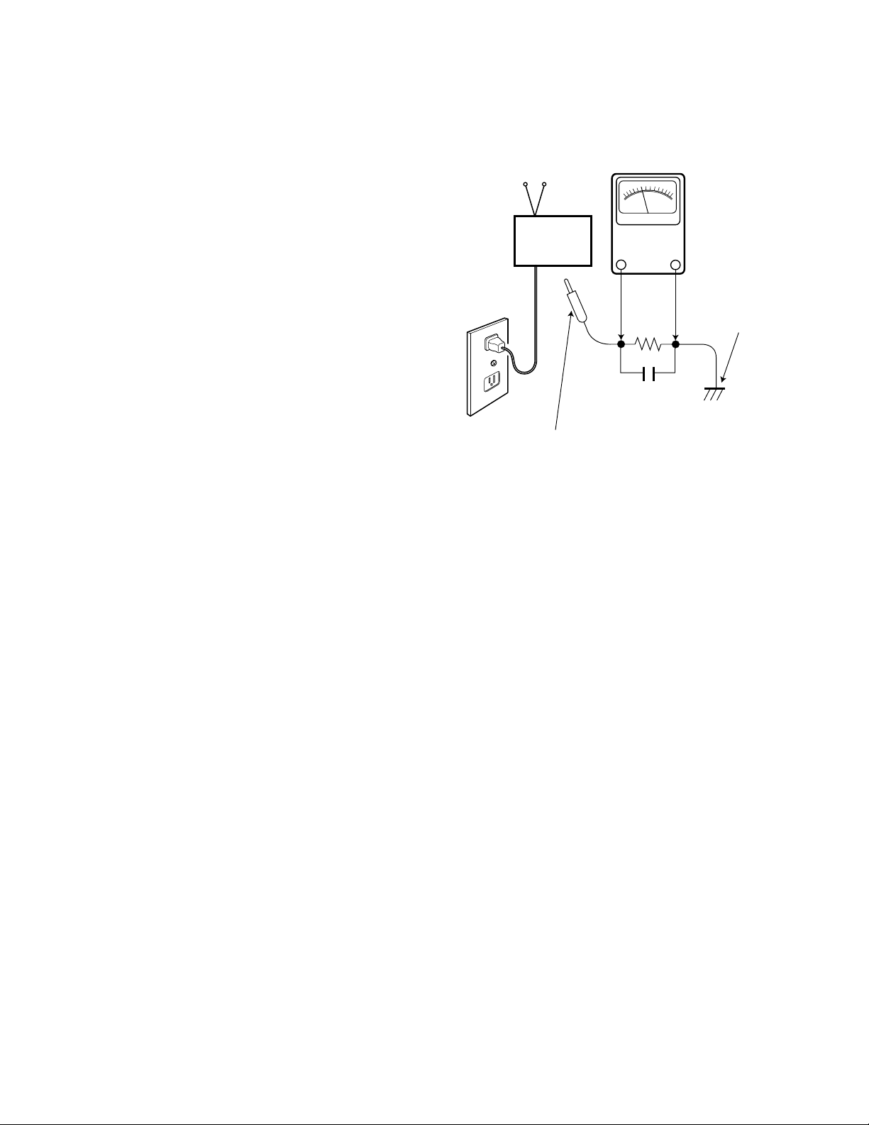
LEAKAGE CURRENT CHECK
Plug the AC line cord directly into a 120 VAC outlet. (Do not
use an isolation transformer for this check.) Use an AC voltmeter, that has 5000 ohms per volt or more sensitivity.
Connect a 1500 ohm 10 watt resistor, paralleled by a 0.15 µF
150 VAC capacitor, between a known good earth ground
(water pipe, conduit, etc.) and all exposed metal parts of the
cabinet (antennas, handle bracket, metal cabinet, screw
heads, metal overlays, control shafts, etc.). Measure the AC
voltage across the 1500 ohm resistor. The AC voltage
should not exceed 750 mV. A reading exceeding 750 mV
indicates that a dangerous potential exists. The fault must
be located and corrected. Repeat the above test with the
receiver power plug reversed.
NEVER RETURN A RECEIVER TO THE CUSTOMER
WITHOUT TAKING THE NECESSARY CORRECTIVE ACTION.
X-RADIATION PRECAUTION
The primary source of X-RADIATION in solid-state receivers is
the picture tube. The picture tube is specially constructed to
limit X-Ray emission. For continued X-RADIATION protection,
the replacement tube must be the same type as the original
(including the suffix letter in the part numbers). Excessive high
voltage may produce potentially hazardous X-RADIATION. To
avoid such hazards, the high voltage must be maintained within
specific limits. Refer to the X-RADIATION WARNING NOTE on
the CHASSIS SCHEMATIC in this service manual for specific
high voltage limits. If the high voltage exceeds specified limits,
check the components specified on the chassis schematic
diagram and take the necessary corrective action. Carefully
follow the instructions for the +B Voltage Check and the High
Voltage Check to maintain the high voltage within the specified
limits.
HIGH VOL T AGE HOLD-DOWN TEST
To prevent X-RADIATION from the picture tube due to
excessive high voltage, a HOLD-DOWN circuit is provided in
the high voltage circuit. Every time the receiver is serviced,
the high voltage HOLD-DOWN circuit must be tested for
proper operation. Refer to the HIGH VOLTAGE HOLDDOWN TEST in service adjustments.
PRODUCT SAFETY NOTICE
When replacing components in a receiver, always keep in
mind the necessary product safety precautions. Pay special
attention to the replacement of components marked with a
star (★) in the parts list and in the schematic diagrams. To
ensure safe product operation, it is necessary to replace
those components with the exact same PARTS.
SAFETY INSTRUCTIONS
READING SHOULD NOT EXCEED 750 mV.
AC VOLTMETER
(5000 ohms per volt or more sensitivity)
TELEVISION
RECEIVER
Good earth ground
such as a water pipe,
conduit, etc.
AC OUTLET
1500 ohm
10 watt
0.15 µF 150V AC
To be touched to all of exposed metal parts.
Voltmeter Hook-up for Leakage Current Check.
GENERAL
This set has an On-screen Service Menu system included in the CPU that allows remote operation for most of the service adjustments.
ON-SCREEN SERVICE MENU SYSTEM
1. Enter the Service Menu:
•While pressing the MENU key, reconnect the AC power cord. The Service Menu Display will now appear. (See Figure 1.)
2. Service Adjustments:
•Press the ▲ or ▼ key to select the desired service menu you want to adjust. (See page 4 for On-screen Service Menu.)
•Use the + or – key to adjust the data.
3. Exit from the Service Menu:
•Press the MENU key to turn off the Service Menu display.
SERVICE AD JUSTMENTS
— 3 —
IC802 (EEPROM) REPLACEMENT
When IC802 (EEPROM) is replaced, IC801 (CPU) will automatically write the initial reference data into IC802 for basic TV operation.
However, the bus data should be checked and some bus data should be set up before attempting the service adjustments.
(See pages 4 – 6 for detailed information.)
INITIAL BUS DATA SETUP
Note: When IC802 (EEPROM) is replaced, the following bus data must be set up for proper TV operation before attempt-
ing the service adjustments.
1. Disconnect the AC power cord (AC 120V line).
2. While pressing the MENU key, reconnect the AC power cord. The Service Menu display will now appear.
3. Select NO. 03 HP (H Phase) with ▲ or ▼ key. Adjust the data with + or – key for 12.
4. Select NO. 04 VS (V Size) with ▲ or ▼ key. Adjust the data with + or – key for 66.
5. Select NO. 05 VPO (V Position) with ▲ or ▼ key. Adjust the data with + or – key for 45.
6. Select NO. 11 HBR (H BLK R) with ▲ or ▼ key. Adjust the data with + or – key for 4.
7. Select NO. 19 GD (Green Drive) with ▲ or ▼ key. Adjust the data with + or – key for 12.
8. Select NO. 23 POS (Pre/Over/SW) with ▲ or ▼ key. Adjust the data with + or – key for 1.
9. Select NO. 29 WP (White Peak Limiter) with ▲ or ▼ key. Adjust the data with + or – key for 1.
10. Select NO. 34 DCR (DC Reset) with ▲ or ▼ key. Adjust the data with + or – key for 1.
11. Select NO. 35 YGM (Y Gamma) with ▲ or ▼ key. Adjust the data with + or – key for 2.
12. Select NO. 37 AF (Auto Flesh) with ▲ or ▼ key. Adjust the data with + or – key for 1.
13. Select NO. 41 RYA (R-Y/B-Y Angle) with ▲ or ▼ key. Adjust the data with + or – key for 2.
14. Select NO. 47 EWD (EW DC) with ▲ or ▼ key. Adjust the data with + or – key for 46.
15. Select NO. 48 EWA (EW Amp) with ▲ or ▼ key. Adjust the data with + or – key for 22.
16. Select NO. 49 EWT (EW Tilt) with ▲ or ▼ key. Adjust the data with + or – key for 36.
17. Select NO. 50 EWP (EW Corner Top) with ▲ or ▼ key. Adjust the data with + or – key for 5.
18. Select NO. 51 EWB (EW Corner Bottom) with ▲ or ▼ key. Adjust the data with + or – key for 7.
19. Select NO. 52 HSC (Horz Size Comp) with ▲ or ▼ key. Adjust the data with + or – key for 6.
20. Select NO. 57 OPT (SA Option ) with ▲ or ▼ key. Adjust the data with + or – key for 88.
21. Select NO. 58 OP2 (SA Option 2) with ▲ or ▼ key. Adjust the data with + or – key for 46.
22. Select NO. 60 ATT (Input Level) with ▲ or ▼ key. Adjust the data with + or – key for 9.
23. Select NO. 63 SBO (Sub Bright Offset) with ▲ or ▼ key. Adjust the data with + or – key for 2.
24. Press the MENU key to turn off the Service Menu display.
NO. DATA
XX OPT XXX XXXXXXXX
Figure 1. Service Menu Display
ITEM NO.
TITLE
BINARY DATA
(8 bit)
DECIMAL DATA
— 4 —
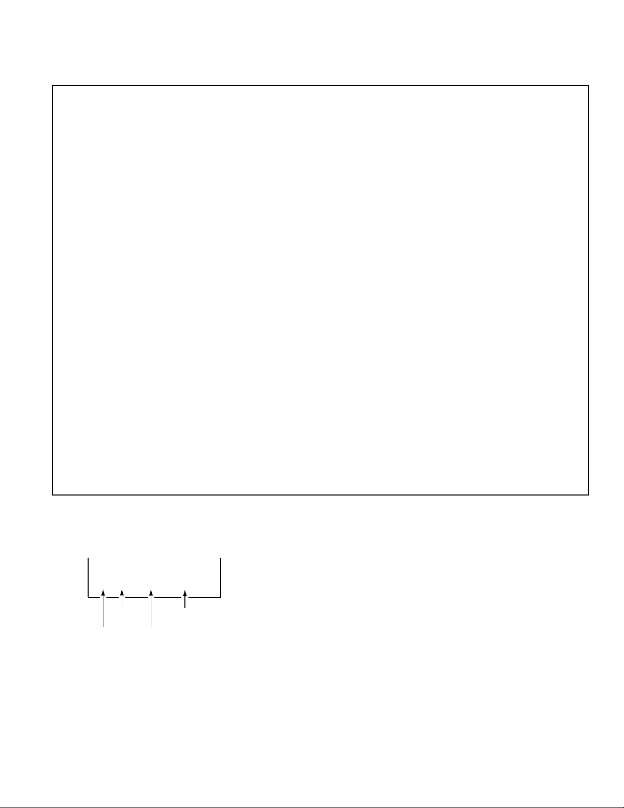
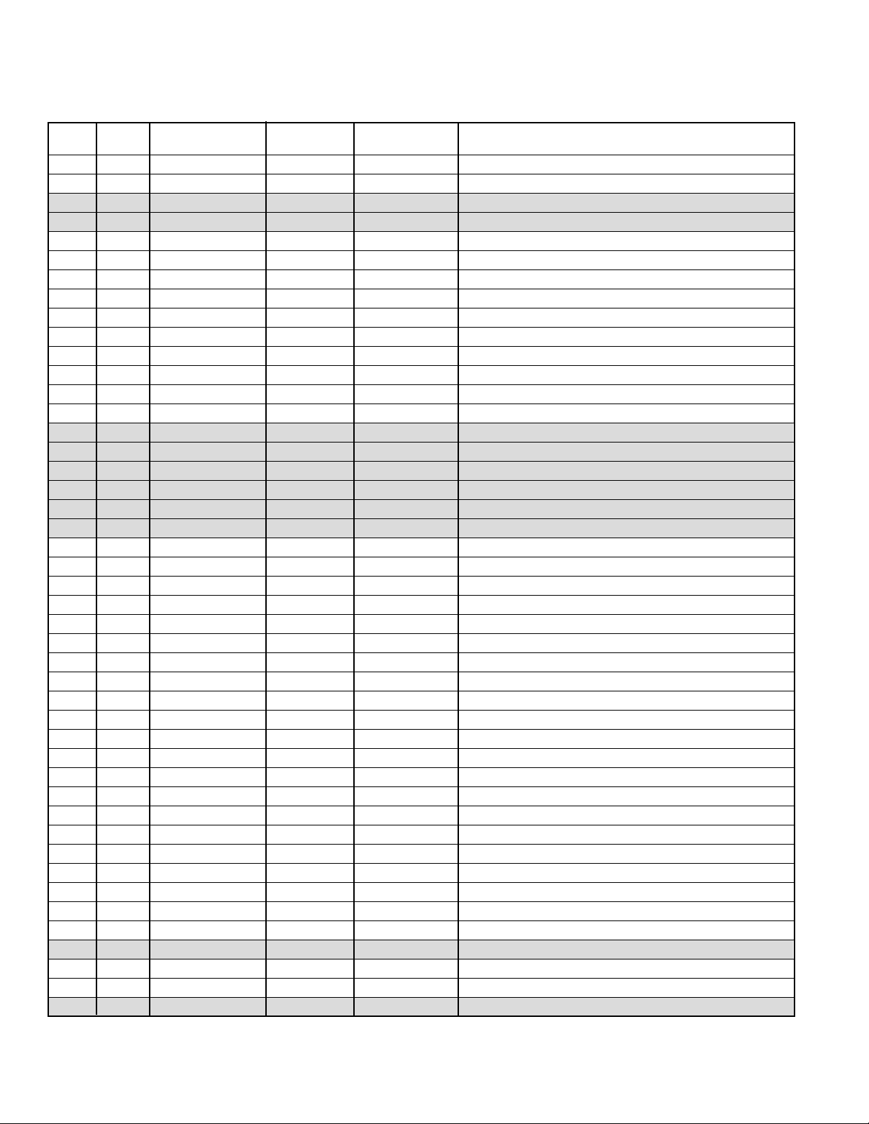
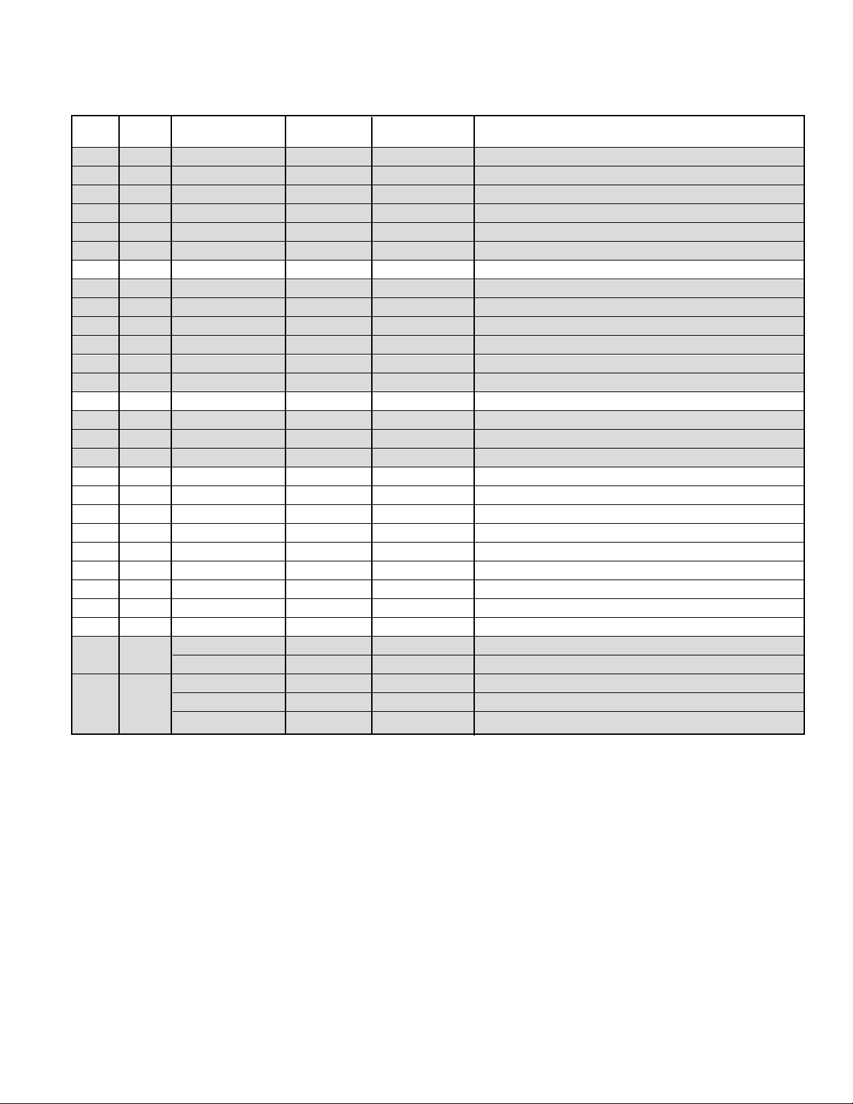
Table 1. ON-SCREEN SERVICE MENU
When IC802 (EEPROM) is replaced, check the bus data to confirm they are the same as below. The shaded menu should be
checked and be set up or readjusted according to the procedures described in the following pages. Initial Setup Data marked
with an * should be changed from Initial Reference Data. (See page 3 for Initial Bus Data Setup.)
NO. TITLE
INITIAL REFERENCE INITIAL SETUP
RANGE OF DATA FUNCTION
DATA DATA
01 HFR 29 29 0~63 Horizontal Frequency
02 AFC 0 0 0, 1 AFC Gain & Gate
03 HP 11 12* 0~31 Horizontal Phase (Horizontal Centering)
04 VS 64 66* 0~127 Vertical Size
05 VPO 32 45* 0~63 Vertical Position
06 VSP 0 0 0, 1 Vertical Set Up (Sync Sensitivity)
07 VLN 17 17 0~31 Vertical Linearity
08 CRS 0 0 0~3 Cross B/W
09 GRY 1 1 0, 1 Gray Mode
10 VSC 10 10 0~31 Vertical S Correction
11 HBR 3 4* 0~7 H BLK R
12 HBL 4 4 0~7 H BLK L
13 CDM 0 0 0, 1 C D Mode
14 VC 5 5 0~7 Vertical Compression
15 RB 0 0 0~255 Red Bias
16 GB 0 0 0~255 Green Bias
17 BB 0 0 0~255 Blue Bias
18 RD 64 64 0~127 Red Drive
19 GD 8 12* 0~15 Green Drive
20 BD 64 64 0~127 Blue Drive
21 SBI 64 64 0~127 Sub Bias
22 OSD 2 2 0~3 OSD Contrast
23 POS 0 1* 0, 1 Pre/Over/SW
24 FLS 2 2 0~7 Filter System
25 CKO 3 3 0~7 Color Killer Operation
26 GYA 0 0 0, 1 G-Y Angle
27 CRG 2 2 0~3 Coring Gain
28 PRE 1 1 0~3 Pre Shoot Adjust
29 WP 0 1* 0, 1 White Peak Limiter
30 FSW 0 0 0, 1 FBP Blanking Switch
31 VBL 0 0 0, 1 Vertical Blanking Switch
32 BSG 1 1 0~3 Black Str Gain
33 BSS 1 1 0~3 Black Str Start
34 DCR 0 1* 0~3 DC Reset
35 YGM 1 2* 0~3 Y Gamma
36 CBP 0 0 0, 1 C Bypass
37 AF 0 1* 0, 1 Auto Flesh
38 BAT 4 4 0~7 Bright ABL Threshold
39 MSD 0 0 0, 1 Mid Stop Def
40 ABL 0 0 0, 1 Auto Bright Limit
41 RYA 4 2* 0~15 R-Y/B-Y Angle
42 RAD 20 20 0~63 RF AGC Delay
43 IAS 0 0 0, 1 IF AGC
44 FMM 0 0 0, 1 FM Mute
45 FL 15 15 0~31 FM Level
— 5 —
Table 1. ON-SCREEN SERVICE MENU (Continued)
When IC802 (EEPROM) is replaced, check the bus data to confirm they are the same as below. The shaded menu should be
checked and be set up or readjusted according to the procedures described in the following pages. Initial Setup Data
marked with an * should be changed from Initial Reference Data. (See page 3 for Initial Bus Data Setup.)
NO. TITLE
INITIAL REFERENCE INITIAL SETUP
RANGE OF DATA FUNCTION
DATA DATA
46 VL 4 4 0~7 Video Level
47 EWD 39 46* 0~63 EW DC
48 EWA 30 22* 0~63 EW Amp
49 EWT 34 36* 0~63 EW Tilt
50 EWP 7 5* 0~7 EW Corner Top
51 EWB 8 7* EW Corner Bottom
52 HSC 4 6* Horiz Size Comp
53 SB 32 32 0~63 Sub Bright
54 SCO 7 7 0~31 Sub Color
55 STI 20 20 0~31 Sub Tint
56 SSH 12 12 0~31 Sub Sharpness
57 OPT 0 88* 0~255 Option (See Note 1 page 6.)
58 OP2 0 46* 0~255 Option 2 (See Note 2 page 6.)
59 HR 24 24 0~63 OSD Horizontal Position
60 ATT 10 9* 0~63 Input Level
61 WDB 32 32 0~63 Wideband
62 SPC 32 32 0~63 Spectral
63 SBO 5 2* 0~255 Sub Bright Offset
64 PCO 40 40 0~63 PIP Color
65 PTI 40 40 0~63 PIP Tint
66 PUV 24 24 0~63 PIP Top Position
67 PDV 147 147 0~255 PIP Bottom Position
68 PLH 10 10 0~63 PIP Left Position
69 PRH 101 101 0~255 PIP Right Position
70 PCN 42 42 0~63 PIP Y Level
71 PBS 15 15 0~63 PIP BGP Phase
72 DRV
64 64 0~127 Red Drive Adjustment (See Note 3 page 6.)
64 64 0~127 Blue Drive Adjustment (See Note 3 page 6.)
– 0 0 0~255 Red Bias Adjustment (See Note 4 page 6.)
73 – 0 0 0~255 Green Bias Adjustment (See Note 4 page 6.)
– 0 0 0~255 Blue Bias Adjustment (See Note 4 page 6.)
— 6 —
SERVICE AD JUSTMENTS (Continued)
PROGRAM CODES
The microprossesor used in this model is a multi-purpose
type and is used in several different models. To ensure
proper operation and the correct features for your particular model, the Program Codes must be correct.
Note 1. Option Data 1 (NO. 57 OPT) should be decimal 88
(01011000 binary). See page 3 INITIAL DATA SETUP, step
20, for set up procedure. If this program code is wrong the
TV will not operate properly.
Note 2. Option Data 2 (NO. 58 OP2) should be decimal 46
(00101110 binary). See page 3 INITIAL DATA SETUP, step
21, for set up procedure. If this program code is wrong the
TV will not operate properly.
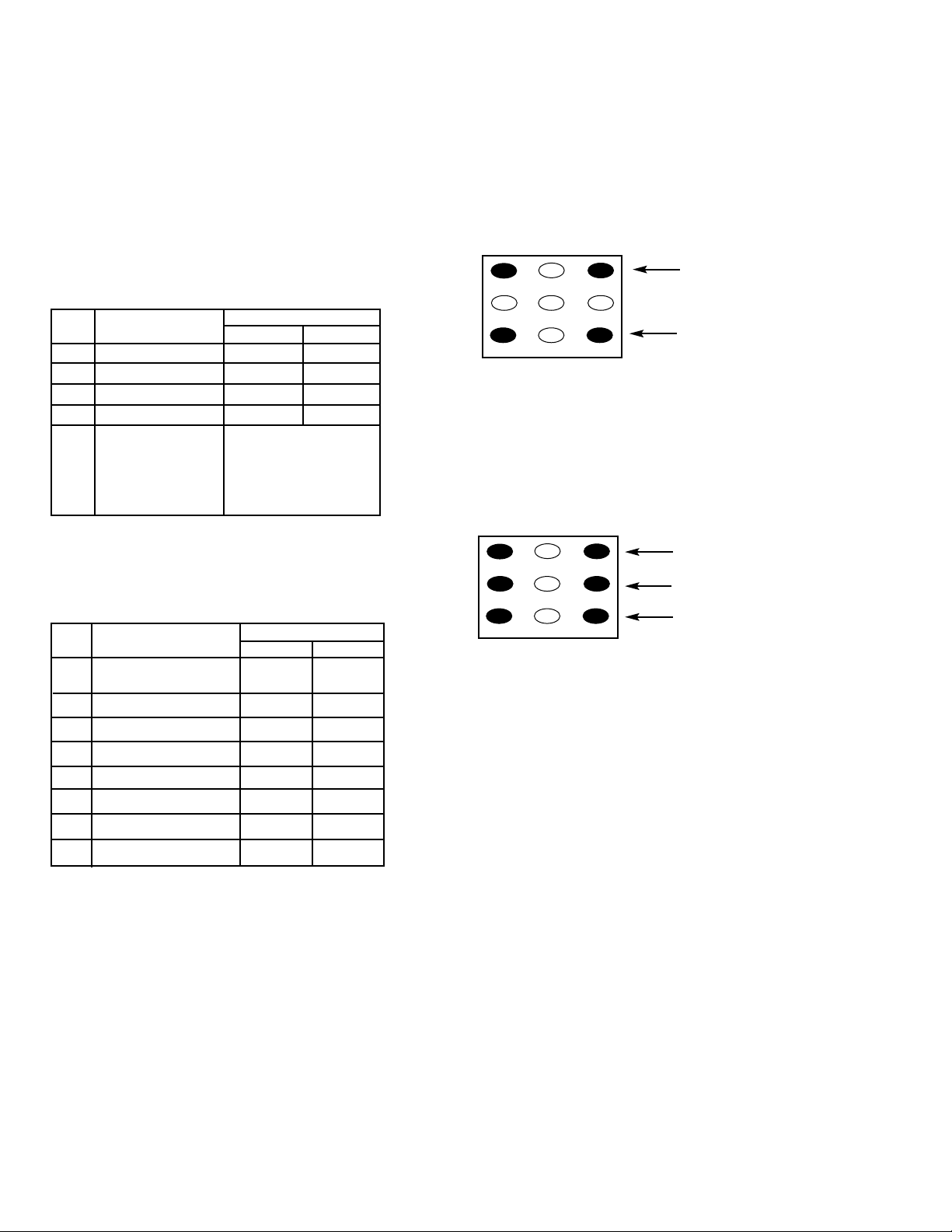
DRIVE / BIAS ADJUSTMENTS
Note 3. Red/Blue Drive Adjustments in Service Menu NO.
72 DRV: Adjust Red and Blue Drive Levels alternately with
1, 3, 7, and 9 keys on the remote control. (See Figure 2.) The
Drive Level adjustment data will be written in the Service
Menu No. 18 and 20 automatically.
1
2
3
4 5 6
7 98
RB(–)
RB(+)
BB(–)
BB(+)
(N/A)
GB(–)
(N/A)
GB(+)
(N/A)
FOR RED BIAS ADJUSTMENT
FOR BLUE BIAS ADJUSTMENT
FOR GREEN BIAS ADJUSTMENT
Figure 2.
Figure 3.
1
2
3
4 5 6
7 98
RD(–)
RD(+)
BD(–)
BD(+)
(N/A)
(N/A)
(N/A)
(N/A)
(N/A)
FOR RED DRIVE ADJUSTMENT
FOR BLUE DRIVE ADJUSTMENT
BIT FUNCTION
DATA
01
0 ~ 2 NOT USED — —
3 CLOCK NONE YES
4 COMB FILTER NONE YES
5 NOT USED — —
00: NONE
6, 7 SURROUND
01: YES
10: —
11: —
Note 4. Red/Green/Blue Bias Adjustments in Service Menu
NO. 73: Adjust each Bias Level with 1, 3, 4, 6, 7, or 9 key on
the remote control. (See Figure 3.) The Bias Level adjustment data will be written in the Service Menu No. 15 ~ 17
automatically.
BIT FUNCTION
DATA
01
0
SHIPPING CONDITION
NORMAL COOL
OF COLOR ENHANCER
1 COLOR ENHANCER NONE YES
2 INITIAL CH & XDS NONE YES
3 AUDIO OUT & SP MENU NONE YES
4 PIP NONE YES
5 AV INPUTS 1 SET 2 SETS
6 BASS & TREBLE / TONE BASS & TR TONE
7 NOT USED
——
— 7 —
ANTENNA CONNECTIONS
This receiver is designed for UHF/VHF reception. A 75 ohm
terminal is provided for UHF and VHF receptions. When
connecting a CATV antenna system, connect the 75 ohm
coaxial cable directly to the 75 ohm terminal. For 300 ohm
VHF antenna, use an adapter (not included with the TV set).
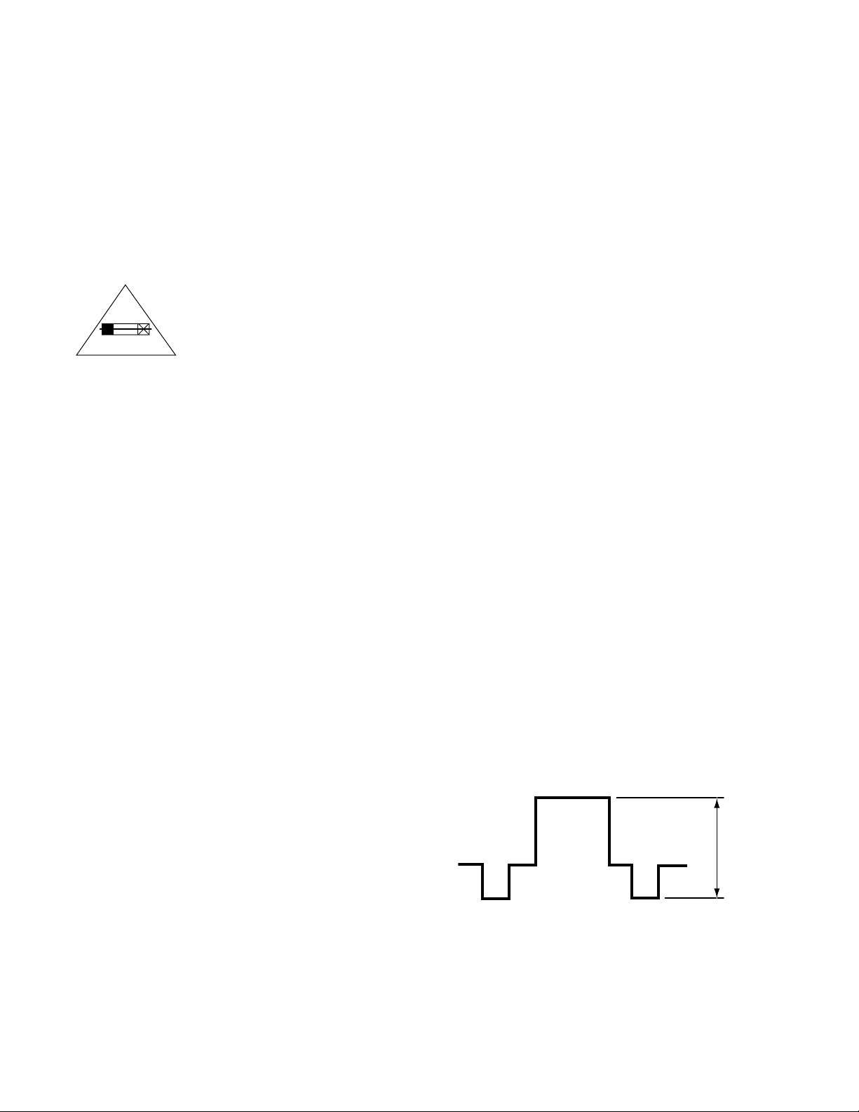
CIRCUIT PROTECTION
Fuse F601 (4A) is included in the AC line. This fuse must be
replaced with the proper fuse (see Parts List).
+B VOL T AGE CHECK
Connect Voltmeter + lead to TJ1 130V and – lead to ground
(TE7). Connect receiver to AC 120V line. Tune receiver to an
active channel. Reset the picture controls to the FACTORY
PRESET levels (press remote control RESET key twice).
Voltage must measure between +133.0V and +137.0V. If the
voltage is out of this range, the power circuit must be
checked. No +B adjustment is provided on this chassis.
HORIZONT AL WIDTH AD JUSTMENT
1. Tune receiver to an active channel.
2. Check the picture for proper width. If width is not correct,
perform steps 3 ~ 6.
3. Turn off the receiver and disconnect the AC power cord
(120V AC line).
4. While pressing the MENU key, reconnect the AC power
cord. The Service Menu display will now appear.
5. Select NO. 47 EWD (EW DC) with ▲ or ▼ key.
6. Adjust the data with + or – key for proper width.To turn
off the Service Menu display, press the MENU key.
HORIZONTAL CENTERING ADJUSTMENT
1. Tune receiver to an active channel.
2. Check that picture is in the horizontal center of TV screen.
If picture is not centered horizontally, perform steps 3 ~ 6.
3. Turn off the receiver and disconnect the AC power cord.
4. While pressing the MENU key, reconnect the AC power
cord. The Service Menu display will now appear.
5. Select NO. 03 HP (Horizontal Phase) with ▲ or ▼ key.
6. Adjust the data with + or – key for horizontal center. To
turn off the Service Menu display, press the MENU key.
VERTICAL SIZE ADJUSTMENT
1. Tune receiver to an active channel.
2. Check the vertical size of the picture. If the vertical size is
too large or small, perform steps 3 ~ 6.
3. Turn off the receiver and disconnect the AC power cord.
4. While pressing the MENU key, reconnect the AC power
cord. The Service Menu display will now appear.
5. Select NO. 04 VS (Vertical Size) with ▲ or ▼ key.
6. Adjust the data with + or – key for full scan. To turn off
the Service Menu display, press the MENU key.
VERTICAL CENTERING ADJUSTMENT
1. Tune receiver to an active channel.
2. Check that picture is in the center of TV screen. If picture
center is too low, change resistor R513 from 1K ohm 1/2W to
470 ohm 1W. If picture center is too high, remove resistor
R513 (1K ohm, 1/2W).
VCO AD JUSTMENT
Note: VCO must be adjusted after IC101 (Signal Processor),
IC802 (EEPROM) or T151 (VCO Coil) is replaced.
1. Tune receiver to an active channel.
2. Set the picture controls to the Sports level.
3. Connect digital voltmeter + lead to pin 58 of IC101 and
– lead to ground (TE 7).
4. Confirm a reading of 3.6 ± 0.2 VDC.
5. If voltage is out of specifications adjust T151 for
3.6 ± 0.2 VDC.
RF AGC ADJUS TMENT
1. Tune receiver to strongest VHF station in your area.
2. Set contrast and brightness controls for maximum.
3. Turn off the receiver and disconnect the AC power cord
(120V AC line).
4. While pressing the MENU key, reconnect the AC power
cord. The Service Menu display will now appear.
5. Select NO. 42 RAD (RF AGC Delay) with ▲ or ▼ key.
6. Adjust the data with + or – key in the direction which
causes snow to appear; then in the opposite direction
until the snow just disappears.
7.To turn off the Service Menu display, press the MENU key.
VIDEO LEVEL
1. Connect color bar generator to antenna terminals.
2. Turn off the receiver and disconnect the AC power cord
(AC 120V line).
3. Connect oscilloscope to TP16A (Q202 emitter) and ground.
4. While pressing the Menu key, reconnect the AC power
cord. The Service Menu will now appear.
5. Select NO. 46 VL (Video Level) with the ▲ or ▼ key.
6. Adjust the + or – key for an oscilloscope reading of 1.0 ±
0.1 VP-P at TP16A. Press the MENU key to turn off the
Service Menu display.
CAUTION
FOR CONTINUED PROTECTION AGAINST
A RISK OF FIRE, REPLACE ONLY WITH
THE SAME TYPE 4A, 125V FUSE.
ATTENTION : POUR MAINTENIR LA PROTECTION CONTRE LES RISQUES
D’ INCENDIE UTILISER UN FUSIBLE DE
RECHANGE DE MEME TYPE 4A, 125V.
1.0 ± 0.1 VP-P
Figure 4.
4A 125V
SERVICE AD JUSTMENTS (Continued)
— 8 —
GRA Y SCALE ADJUS TMENT
1. Set the picture controls to the Sports levels or Reset
(use MENU key and ▲ or ▼ key or RESET key).
2. Turn off the receiver and disconnect the AC power cord
(120V AC line).
3. While pressing the MENU key, reconnect the AC power
cord. The Service Menu display will now appear.
4. Select NO. 15 RB (Red Bias), NO. 16 GB (Green Bias),
and NO. 17 BB (Blue Bias) with ▲ or ▼ key and set each
data to 0 with + or – key.
5. Select NO. 18 RD (Red Drive) and NO. 20 BD (Blue Drive)
with ▲ or ▼ key and set each data to 64 with + or – key.
6. Set NO. 19 GD (Green Drive Reduction) data to 8, NO. 53
SB (Sub Brightness) data to 32, NO. 54 SCO (Sub Color)
data to 7, NO. 55 STI (Sub Tint) to 20, and NO. 56 SSH
(Sub Sharpness) data to 12 with ▲ or ▼, and + or – keys.
7. Turn Screen Control (T402) to minimum (fully counterclockwise).
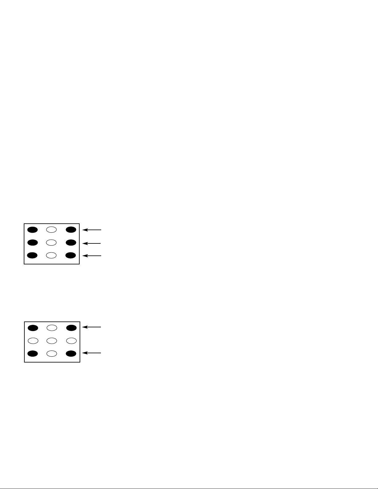
8. Select the Service Menu NO. 73 (Bias Adjustments) with
▲ or ▼ key.
9. Advance Screen Control (T402) clockwise to obtain just
visible one color line. If line does not appear, place this
control to maximum (fully clockwise).
10. Raise each Bias Level with 3, 6, and 9 keys to obtain just
visible white line. (See Figure 5.)
11. Select the Service Menu NO. 72 DRV (Drive Adjustments)
with ▲ or ▼ key.
12. Adjust Red and Blue Drive Levels alternately with 1, 3,
7, or 9 key to produce normal black and white picture in
highlight areas. (See Figure 6.)
13. Check for proper grayscale at all brightness levels.
To turn off the Service Menu display, press the MENU key.
Note: If Grayscale Adjustment is made after picture tube
replacement, check Brightness Level Adjustment.
BRIGHTNESS LEVEL ADJUSTMENT
Note: Grayscale, RF AGC, Video Level, and High Voltage Check
must be adjusted before attempting Brightness Level
Adjustment.
1. Connect a color-bar generator to the antenna terminals.
2. Switch the generator to the crosshatch pattern.
3. Reset the picture controls to the Sports levels.
4. Connect voltmeter (high impedance) + lead to terminal
TP51 and – lead to terminal TP50 on main board. Set
voltmeter for 1.5V ~ 3V range.
5. Turn off the receiver and disconnect the AC power cord.
6. While pressing the MENU key, reconnect the AC power
cord. The Service Menu display will now appear.
7. Select NO. 53 SB (Sub Brightness) with ▲ or ▼ key.
8. Adjust the data with + or – key for 680 mVDC.
9. Press the MENU key to turn off the Service Menu display.
10. Check brightness level on every active channel, readjust
(repeat steps 5 ~ 9), if necessary.
Note: Do not set to excessive brightness level, otherwise
the contrast level will be suppressed.
HIGH VOL T AGE HOLD-DOWN TEST
Every time the receiver is serviced, the HIGH VOLTAGE
HOLD-DOWN circuit must be tested for proper operation by
following these steps:
1. Connect receiver to 120V AC line. Tune receiver to active
channel. Reset the picture controls to the Sports levels.
2. Check that the voltage measured between TP7 and TE7
(ground side) is within 16.5 VDC to 21 VDC. If the voltage
is out of this range, the Hold-Down Circuit must be checked.
3. Connect a DC Voltage supply to TP7 and TE7 through a
100 ohm 1/4W resistor. Adjust the DC voltage to 23 VDC.
The receiver should shutdown, losing raster and sound.
Then the receiver should turn off automatically. This
reaction indicates that the Hold-Down circuit is functioning properly. If the receiver does not shutdown, a
malfunction is indicated and its cause must be found and
corrected.
4. To obtain picture again, remove the DC Supply and wait
a few minutes. Now turn on the receiver.
HIGH VOL T AGE CHECK
Note: +B (+130V) Voltage Check and Grayscale Adjustment
must be completed before attempting High Voltage
Check.
1. Connect high voltage voltmeter – lead to ground, and
connect + lead to anode of picture tube.
2. Tune receiver to an active channel and confirm TV is
operating properly.
3. Eliminate the beam current by adjusting the contrast and
brightness controls to minimum.
4. Confirm high voltage is within 28.6 KV and 33.5 KV. If
reading is not within range, check horizontal circuit.
No high-voltage adjustment is provided on this chassis.
1
2
3
4 5 6
7 98
RB(–)
RB(+)
BB(–)
BB(+)
(N/A)
GB(–)
(N/A)
GB(+)
(N/A)
FOR RED BIAS ADJUSTMENT
FOR BLUE BIAS ADJUSTMENT
FOR GREEN BIAS ADJUSTMENT
Figure 5. Remote Control Number keys’ functions in
Service Menu NO. 73
1
2
3
4 5 6
7 98
RD(–)
RD(+)
BD(–)
BD(+)
(N/A)
(N/A)
(N/A)
(N/A)
(N/A)
Figure 6. Remote Control Number keys’ functions in
Service Menu NO. 72 DRV
FOR RED DRIVE ADJUSTMENT
FOR BLUE DRIVE ADJUSTMENT
— 9 —
FOCUS ADJUSTMENT
1. Connect a color-bar generator to the antenna terminals
and select a crosshatch pattern.
2. Set the picture controls to the Sports levels.
3. Select a vertical line at the center of the screen and
adjust the H focus control for best focus.
4. Select a horizontal line at the top of the screen and
adjust the V focus control for best focus.
5. Repeat steps 3 and 4 for best focus.
SOUND ADJUSTMENT
1. Connect a color-bar generator to the antenna terminals
with audio signal of 1KHz at 100% modulation.
2. Set the picture controls to the Sports levels
3. Connect oscilloscope + lead to TP21 (pin 75 of IC101)
and – lead to ground.
4. Turn off the receiver and disconnect the AC power cord
(AC 120V line).
5. While pressing the Menu key, reconnect the AC power
cord. The Service Menu will now appear.
6. Select NO. 45 FL (FM Level) with the ▲ or ▼ key.
7. Adjust the data with the + or – key for an oscilloscope
reading of 0.693 ± 10% VP-P at TP21.
8. Press the MENU key to turn off the Service Menu display
and disconnect the oscilloscope from the chassis.
MULTI-SOUND SECTION ADJUSTMENTS
Note: Multi-Sound Section must be adjusted after
IC101 (Signal Processor), IC3401 (MTS Decoder), or
IC802 (EEPROM) is replaced.
INPUT LEVEL ADJUSTMENT
1. Connect a signal to the antenna terminals with audio of
1 KHZ 100% modulation.
2. Turn off the receiver and disconnect the AC power cord
(AC 120V line).
3. Connect voltmeter (RMS) to TP317 and ground.
4. While pressing the Menu key, reconnect the AC power
cord. The Service Menu will now appear.
5. Select NO. 60 ATT (Attenuation) with the ▲ or ▼ key.
6. Adjust the + or – key for a voltmeter reading of 400 ± 20
mVrms at TP317.
SEP ARA TION AD JUSTMENT
7. Turn off the receiver and disconnect the AC power cord
(AC 120V line).
8. Connect oscilloscope CH1 to TP317 and CH2 to TP318
and ground.
9. Connect an MTS TV/Stereo generator to antenna terminal.
10. While pressing the Menu key, reconnect the AC power
cord. The Service Menu will now appear.
11. Select pilot, 300Hz audio frequency and Left modulating
signal.
12. Select NO. 61 WDB (Wideband) with the ▲ or ▼ key.
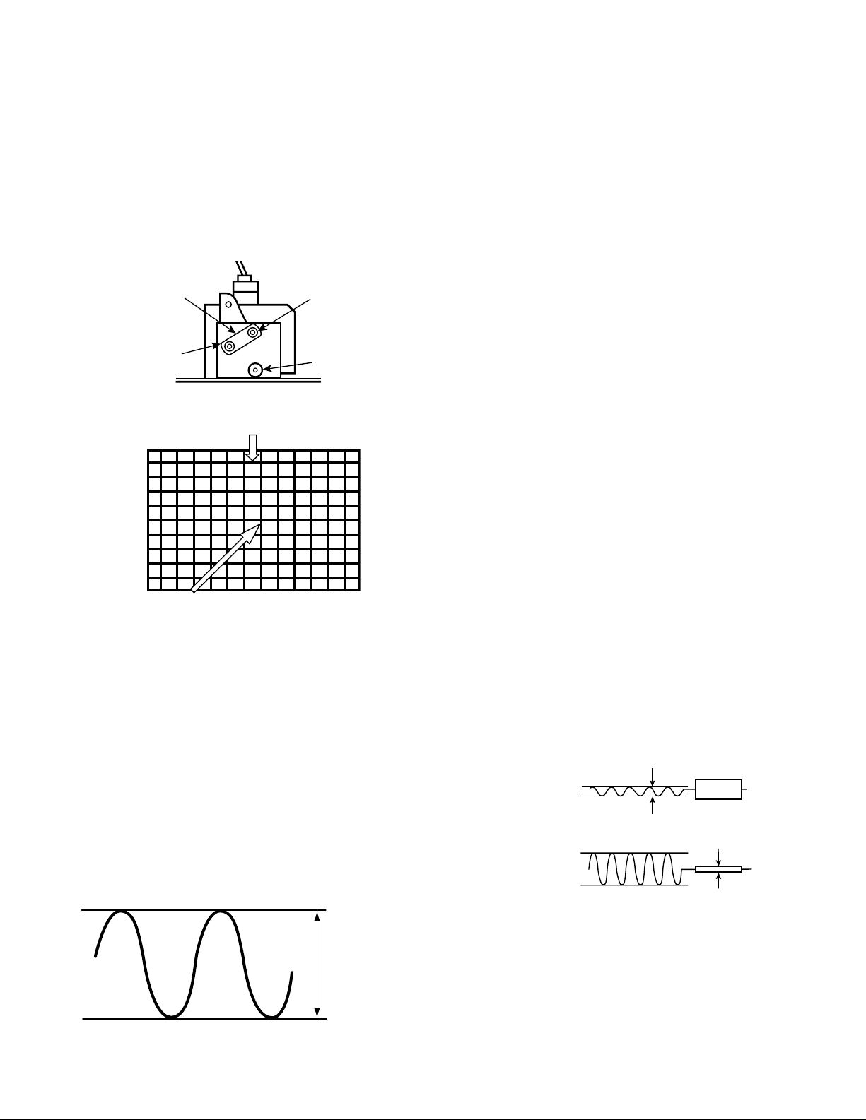
13. Adjust the + or – key for minimum low frequencies at
TP317. (See Figure 10.)
14. Select 4 KHz audio frequency and Right modulating signal.
15. Select NO. 62 SPC (Spectral) with the ▲ or ▼ key.
16. Adjust the + or – key for minimum high frequencies at
TP318. (See Figure 10.)
Repeat adjustments (steps 11–16) until no further decreases
in amplitude can be obtained. Press the MENU key to turn
off the Service Menu display.
PURITY AND CONVERGENCE ADJUSTMENTS
Purity and Convergence have been aligned at the factory.
No re-alignment is necessary.
Figure 10. Separation Adjustments
0.693 ± 10% VP-P
Figure 9.
Focus
H
V
Screen
Adjust the focus of this line using V focus control.
Adjust the focus of this line using H focus control.
Figure 7. Focus controls location
Figure 8. Focus adjustment
Minimize L leakage
TP317 (R)
300Hz
Minimize R leakage
TP318 (L)
4KHz
 Loading...