


Sanyo DC-TS760 User Manual 2
INSTRUCTION MANUAL
REMOTE CONTROLLER RB-TS760ST
DVD Home Theatre System
DC-TS760
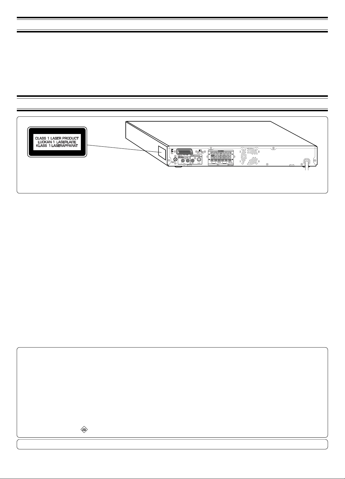
TABLE OF CONTENTS
PRECAUTIONS .......................................... 1
CONTROLS ................................................ 2
REMOTE CONTROL .................................. 3
BASIC CONNECTIONS .............................. 4
ADDITIONAL CONNECTIONS EXAMPLES .......
SYSTEM CONNECTIONS EXAMPLES ...... 8
BEFORE OPERATION ..............................10
VARIOUS ADJUSTING ............................. 11
PLAYABLE DISCS .................................... 12
DISC PLAY ............................................... 13
VARIOUS DISC PLAYING FUNCTIONS .... 14
7
MP3/WMA CD OPERATION ....................... 18
PICTURE CD OPERATION ........................ 19
INITIAL SETTINGS FOR DVD ................... 20
LANGUAGE CODE LIST ........................... 22
LISTENING TO OTHER SOURCES ........ 22
LISTENING TO THE RADIO .................... 23
SLEEP TIMER OPERATION .................... 24
MAINTENANCE ....................................... 24
TROUBLESHOOTING GUIDE ................. 25
SPECIFICATIONS .................................... 26
PRECAUTIONS
CAUTION
THIS PRODUCT CONTAINS A LOW POWER LASER DEVICE, TO ENSURE CONTINUED SAFETY DO NOT REMOVE ANY COVERS OR
ATTEMPT TO GAIN ACCESS TO THE INSIDE OF THE PRODUCT. REFER ALL SERVICING TO QUALIFIED PERSONNEL.
- The apparatus shall not be exposed to dripping or splashing.
- No objects filled with liquids, such as vases, shall be placed on the
apparatus.
- Do not use where there are extremes of temperature (below 5°C or
exceeding 35°C) or where direct sunlight may strike it.
- Because of the DVD player’s extremely low noise and wide dynamic
range, there might be a tendency to set the volume on the amplifier
unnecessarily high. Doing so may produce an excessively large
output from the amplifier which could damage your speakers.
- Sudden changes in the ambient temperature may cause condensation
to form on the optical lens inside the unit. If this happens, take out the
disc, leave the unit for about 1 hour, and then proceed to operate.
- When carrying the unit, be sure to remove any disc which may be
inside and turn the power off. Wait at least 10 seconds, then unplug
the mains lead from the AC outlet. Carrying the unit with a disc inside
may damage the disc and/or the unit.
- Do not install this equipment in a confined space, such as a book case
or built in cabinet.
- The unit is automatically set to the screen saver mode after
approximately 15 minutes have elapsed under the stop or pause
mode.
- Placing the unit in a well ventilated area is strongly recommended.
Do not place any object on the top of the unit.
Do not block ventilation holes.
The cabinet of the unit warms up when it is used for a long time, but
it is not a malfunction.
Important Information:
To connect this unit to a TV, TV must have a Video input socket or an
EURO-AV/SCART socket. You cannot use an RF input socket or aerial
terminal to connect this unit.
This product incorporates copyright protection technology that is protected
by method claims of certain U.S. patents and other intellectual property
rights owned by Macrovision Corporation and other rights owners. Use of
this copyright protection technology must be authorized by Macrovision
Corporation, and is intended for home and other limited viewing uses only
unless otherwise authorized by Macrovision Corporation. Reverse
engineering or disassembly is prohibited.
IMPORTANT
If the plug supplied with this equipment is not suitable for the socket
outlets in your home it should be cut off and replaced with the correct
type.
Disposal of Plug
If the non rewireable plug is to be cut off, the removed plug should be
disposed of carefully as there is a shock hazard should the plug be
inserted into a live socket.
Replacing Fuse
The detachable fuse cover must be replaced after changing the fuse.
Only a 3A fuse should be used and should comply with BS1362 and
should carry the ASTA mark .
The unit is not disconnected from the mains unless it is unplugged from the AC outlet.
The wires in the mains lead are coloured in accordance with the following
code;
The wires in the mains lead must be connected to the terminals in the
plug as follows;
Do not connect either wire to the earth terminal.
If the mains plug contains a fuse this should be 3A, if a plug without a fuse
is used the distribution board fuse should not be greater than 5A.
1
Blue Neutral
Brown Live
Wire colour Plug terminal marking
Blue N or Black or Blue
Brown L or Red or Brown
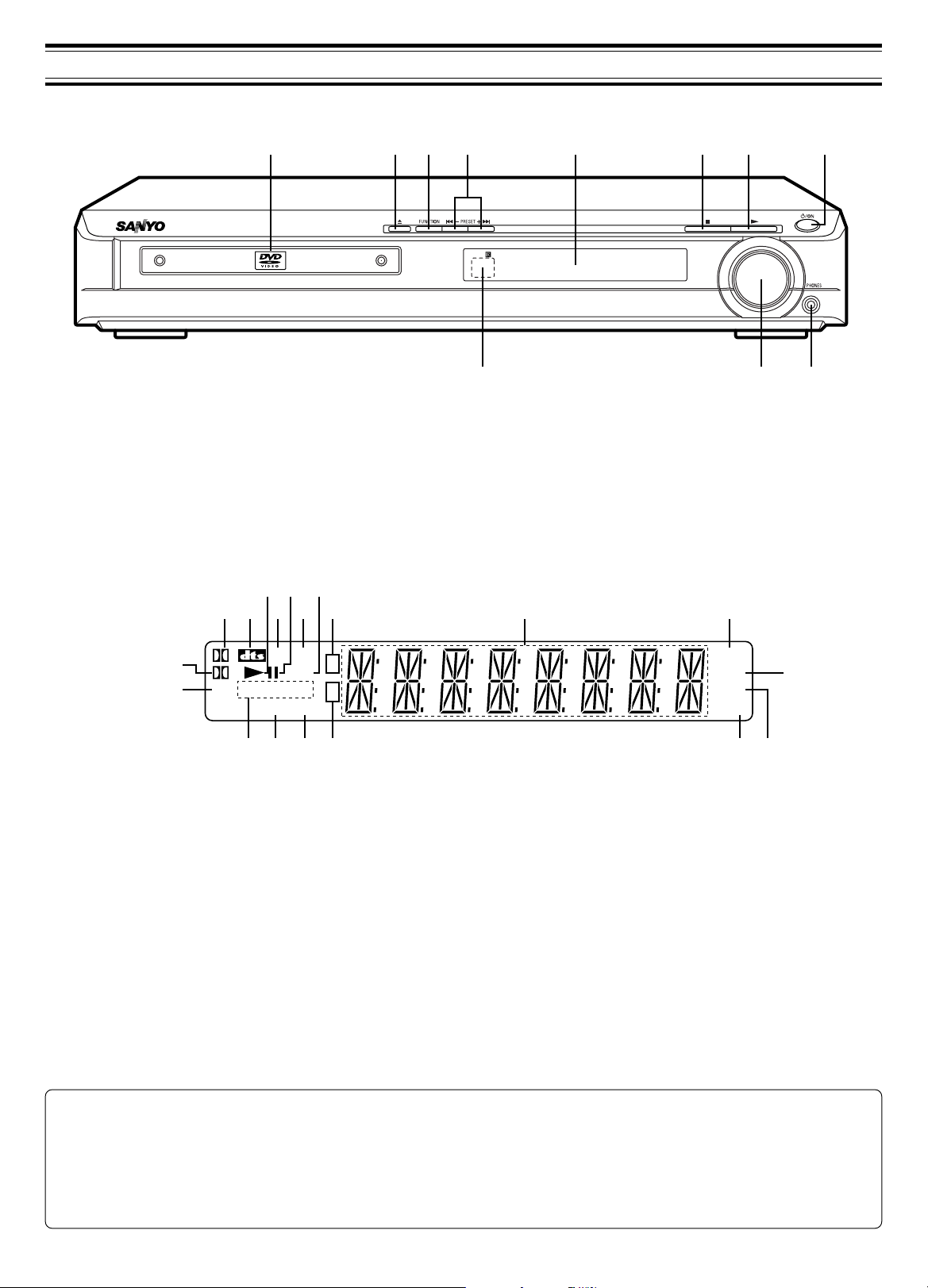
Front panel
CONTROLS
2 3 6 7 84 51
11 10 9
1. Disc tray
2. Open/Close button (q)
3. Function button (FUNCTION)
4. Preset tuning, Skip/Next/Previous buttons (f – PRESET + e)
5. Display
6. Stop button (n)
Display
3 75
1 102 8 94 6
D
19
18
PGM ALL REP.1A-
L.M. MP3
PL
L R RND
16
17
1. Dolby Digital indicator (s D)
2. DTS indicator (dts)
3. Play indicator (a)
4. Last memory indicator (L.M.)
5. Pause indicator (k)
6. MP3 indicator (MP3)
7. WMA indicator (WMA)
8. Title and Track indicator (T)
9. Message or number indicators
(Title, chapter, track, playing time or other information)
WMA
B
15
T
C
7. Play button (a)
8. Power button (z/ON)
9. Headphones socket (PHONES)
10. Volume control (VOLUME)
11. Remote sensor (IR)
SLEEP
RDS
MONO
ST
10. Sleep indicator (SLEEP)
11. RDS indicator (RDS)
12. FM mono indicator (MONO)
13. FM stereo indicator (ST)
14. Chapter indicator (C)
15. Random play indicator (RND)
16. Audio channel indicator (L, R)
17. Repeat mode indicators (ALL, REP., 1, A-B)
18. Programme indicator (PGM)
19. Dolby Pro Logic indicator (s PL)
11
121314
RB-TS760ST remote control
R6 (HP 7) battery x 2
AM loop aerial
FM aerial wire
Video lead
Front right speaker lead (Black and Red)
ACCESSORIES
Front left speaker lead (Black and White)
Centre speaker lead (Black and Green)
Surround right speaker lead (Black and Gray)
Surround left speaker lead (Black and Blue)
Subwoofer lead (Black and Violet)
Screw kit
2
Note:
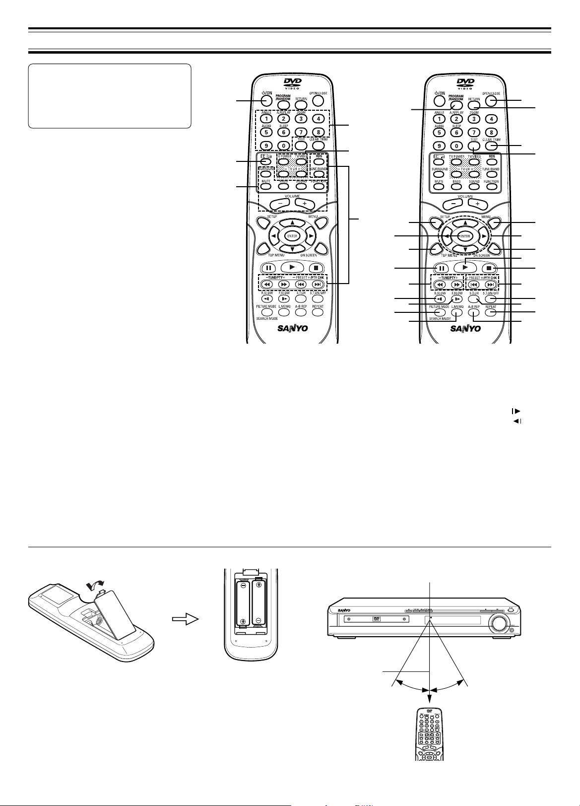
REMOTE CONTROLLER RB-TS760ST
30
22
24
25
29
27
26
28
23
21
7
10
12
8
9
14
15
17
19
18
11
13
16
20
In this instruction manual, any operation of
pressing any button while pressing the SHIFT
button is as shown below.
Example: “Press the SHIFT + 1 ANGLE
buttons.”
Controls
1. Power button (z/ON)
2. Number and other function buttons
Number buttons (1 - 9, 0)
Angle button (ANGLE)
Angle replay button (A.REPLAY)
Zoom button (ZOOM)
Audio button (AUDIO)
Sleep button (SLEEP)
3. TV control buttons
Note:
- Only SANYO TVs can be operated
using this remote control.
- There may be some TV models that
cannot be operated with this remote
control. If this is the case, use the original
remote control supplied with the TV.
Power button (TV POWER)
TV/Video select button (TV/VIDEO)
Channel scanning buttons (TV CH)
4. Tuner controls
Radio data system mode
Tuner function/Band select button (TUNE/
BAND)
Tuning/Programme type select buttons
(TUNE/PTY)
Preset tuning/Programme type check
buttons (PRESET/PTY CHK)
5. Amplifier controls
Surround button (SURROUND)
Muting button (MUTE)
Bass button (BASS)
Sound preset button (SOUND)
Function button (FUNCTION)
Volume buttons (VOLUME)
6. Shift button (SHIFT)
7. Open/Close button (OPEN/CLOSE)
button (
RDS
REMOTE CONTROL
1
2
3
6
5
4
REMOTE CONTROLLER RB-TS760ST
)
8. Return button (RETURN)
9. Clear/Trim button (CLEAR/TRIM)
10. Test tone button (TEST)
11. Menu button (MENU)
12. Directional arrow buttons (4, a, 5, b)
13. On-screen display button (ON SCREEN)
14. Play button (a)
15. Stop button (n)
16. Skip/Next/Previous buttons (f, e)
17. Subtitle on/off button (S.T.ON/OFF)
18. Subtitle change button (S.T.CH)
19. Repeat button (REPEAT)
20. A-B repeat button (A-B REP)
21. Last memory button (L.MEMO)
22. Picture mode/Search mode button
(PICTURE MODE/SEARCH MODE)
23. Forward slow button (F.SLOW )
24. Reverse slow button (R.SLOW )
25. Fast forward/Fast reverse buttons (d, c)
26. Pause/Step button (k)
27. Top menu button (TOP MENU)
28. Enter button (ENTER)
29. Setup button (SETUP)
30. Programme/Random play button
(PROGRAM/RANDOM)
Inserting batteries
Install two “R6 (HP 7)” batteries.
Note:
Remove the batteries if the remote control is not to be used for a month
or more. Batteries left in the unit may leak and cause damage.
3
Remote control range
Within approx.
6 meters
Remote sensor
30°30°
BASIC CONNECTIONS
After all connections have been made, connect the mains lead to an AC outlet .
Note:
- Do not connect the mains lead to an AC outlet until all connections have been made.
- The system is not completely disconnected from the mains when the z/ON button is set to the z position.
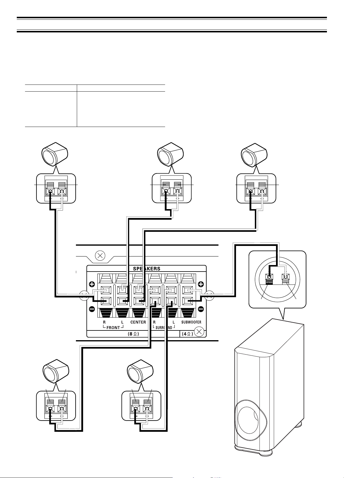
Speaker connections
To achieve proper stereo reproduction, connect the speaker wires without shorting to adjacent wires as shown in figure.
Speaker wire colour Use
Black and Red Front right speaker
Black and White Front left speaker
Black and Green Centre speaker
Black and Gray Surround right speaker
Black and Blue Surround left speaker
Black and Violet Subwoofer
Front right speaker Front left speaker Centre speaker
Black Red Black Red Black Red
Black Red Black Black
Note:
The SPEAKERS sockets are designed for use only with the supplied
speakers. Do not use with other speakers. Connecting other speaker may
damage the speaker and/or the unit.
If using other speakers, check their impedance/input power.
FRONT/CENTER/SURROUND: 8 Ω or more/50 W or more
SUBWOOFER: 4 Ω or more/80 W or more
White
Green
JCX-TS760
Black
Violet
Surround right speaker Surround left speaker
Black Red
Black Black
Gray Blue
Black Red
INPUT
Black Red
Subwoofer
4
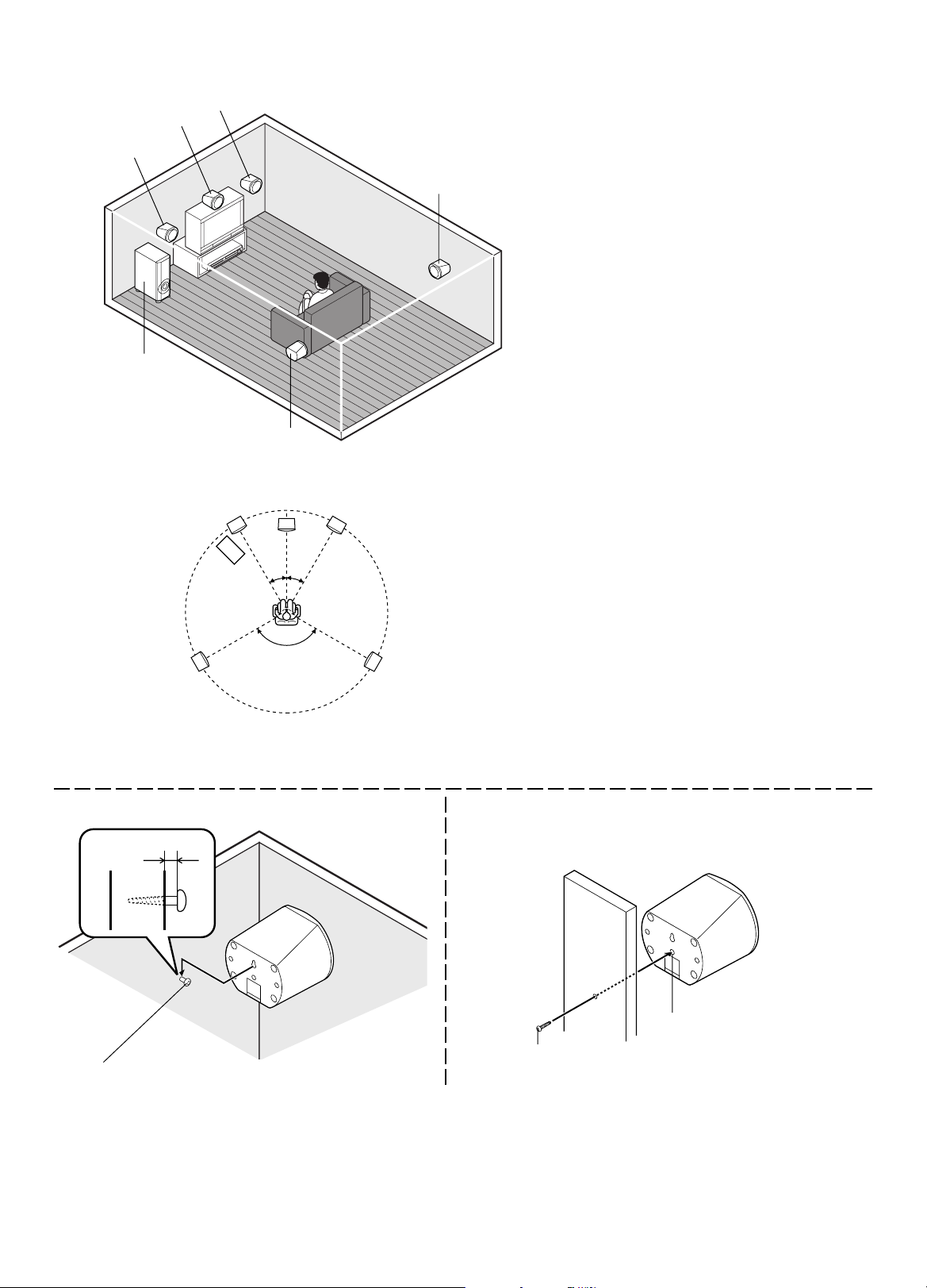
Speaker placement
Front right speaker
Centre speaker
Front left speaker
Subwoofer
Front left speaker Front right speaker
Subwoofer
Surround left
speaker
Surround left speaker
Centre speaker
30°30°
120°
Surround right speaker
Surround right
speaker
The supplied speakers have built-in magnetic stray
field compensation. They may be placed close to a
TV without affecting the colour purity.
The five speakers are all the same and can be used
for front left, centre, front right, surround left and
surround right speakers.
The front, centre, and surround speakers should be placed at
approximately the same distance from the listening position.
Place the front left and right speakers either side of the TV.
Place the centre speaker directly above the TV.
Place the surround speakers either sides of the listening
position, or slightly to the rear, approximately 60 cm ~ 1 meter
higher than ear level.
The subwoofer can be placed near the front speaker and not
too far from the TV.
Note:
- The angles in the diagramme are approximate.
- Please refer to “Setting audio” on Page 21.
Example: To hang the speaker on a wall Example: To mount the speaker with a stand
Approx. 3 mm
Stand (not supplied)
Built-in special nut, 3/16 inch
diameter
Round head screw
(not supplied)
Note: Take care when installing the speakers. They may cause damage or serious injury should they fall from their mountings.
Screw (supplied)
5
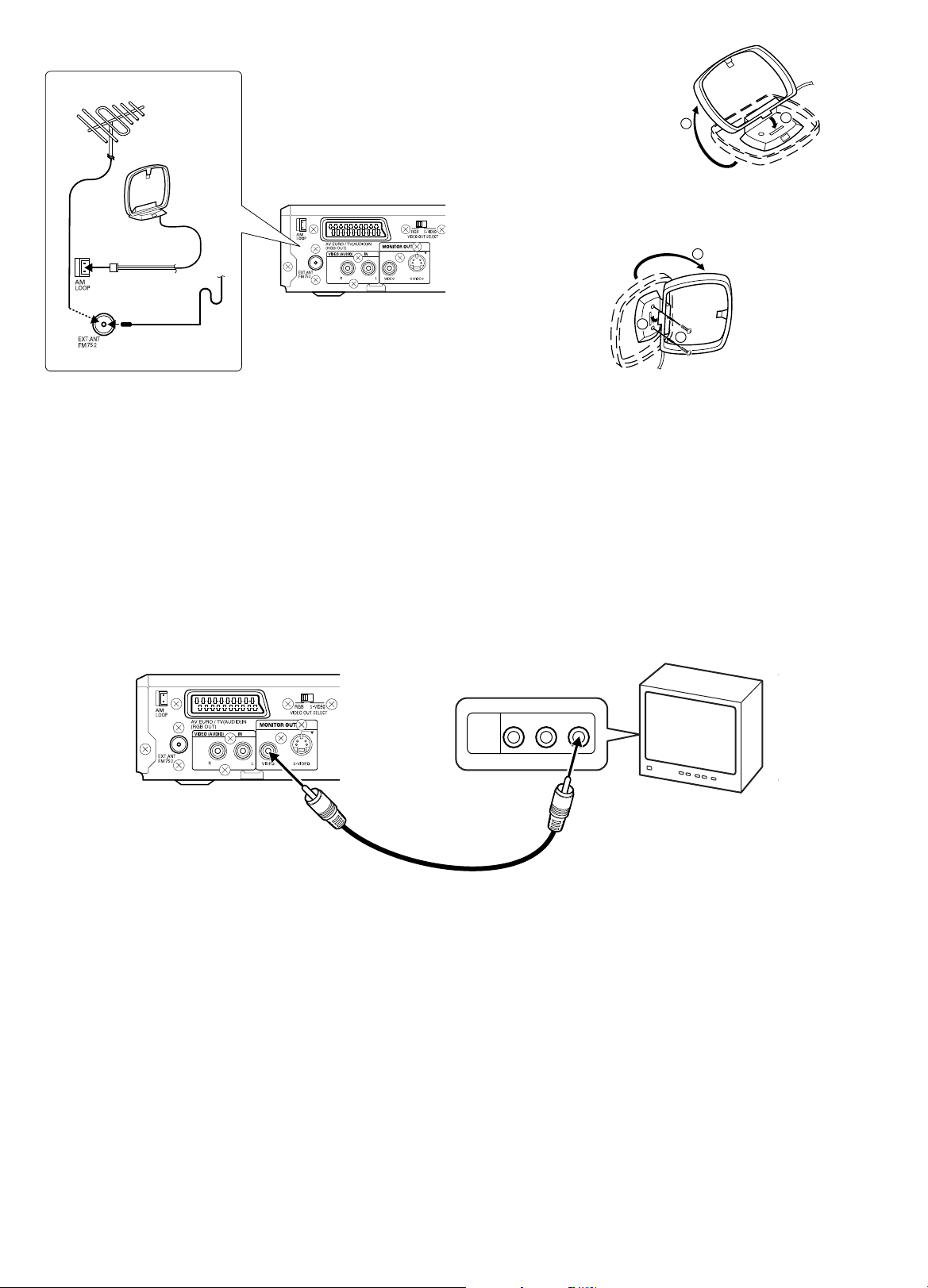
Aerial connections
1
2
FM external aerial
AM loop aerial
AM loop aerial
Assemble the loop aerial.
JCX-TS760
Unwind the aerial wires, then connect the plug to the AM LOOP terminal.
If you have difficulty inserting the plug, turn it over and reinsert it. Place the
loop aerial in a position which yields the best AM reception, or attach it to
a wall or other surface.
3
Aerial wire
2
Screws (not supplied)
In areas close to a transmitter the simple indoor aerial is sufficient to
receive broadcasts. Extend the aerial wire as straight as possible and,
while listening to the sound from the system, secure it in a position which
yields minimal distortion and noise.
Note:
To minimize noise, the speaker, mains and any other leads should not
come close to the indoor or external aerial lead and AM loop aerial. Do not
place the aerial leads close to the system.
In fringe areas or where reception is distorted or noisy, an FM external
aerial (not supplied) should be connected instead of the simple indoor
aerial. Consult your dealer.
Connecting to a TV with the video lead
Connect the video lead between the MONITOR OUT VIDEO socket of the unit and the video input socket of the TV.
JCX-TS760
1
TV
AUDIO
R-AUDIO-L VIDEO
VIDEO
INPUT
1
Video lead
Notes on connections
- Please refer to the instruction manuals for the components that you are connecting (TV, VCR, etc.).
- When you connect the unit to your TV and other equipment, be sure to turn off the power and disconnect all of the equipments from the AC outlet until
all the connections have been made.
- Do not connect the MONITOR OUT (S-VIDEO/VIDEO) and AV EURO/TV (AUDIO) IN (RGB OUT) sockets of the unit to a VCR directly. The
playback picture will be distorted because DVD discs are copy protected.
- Please consult your local audio/video dealer for more details.
6
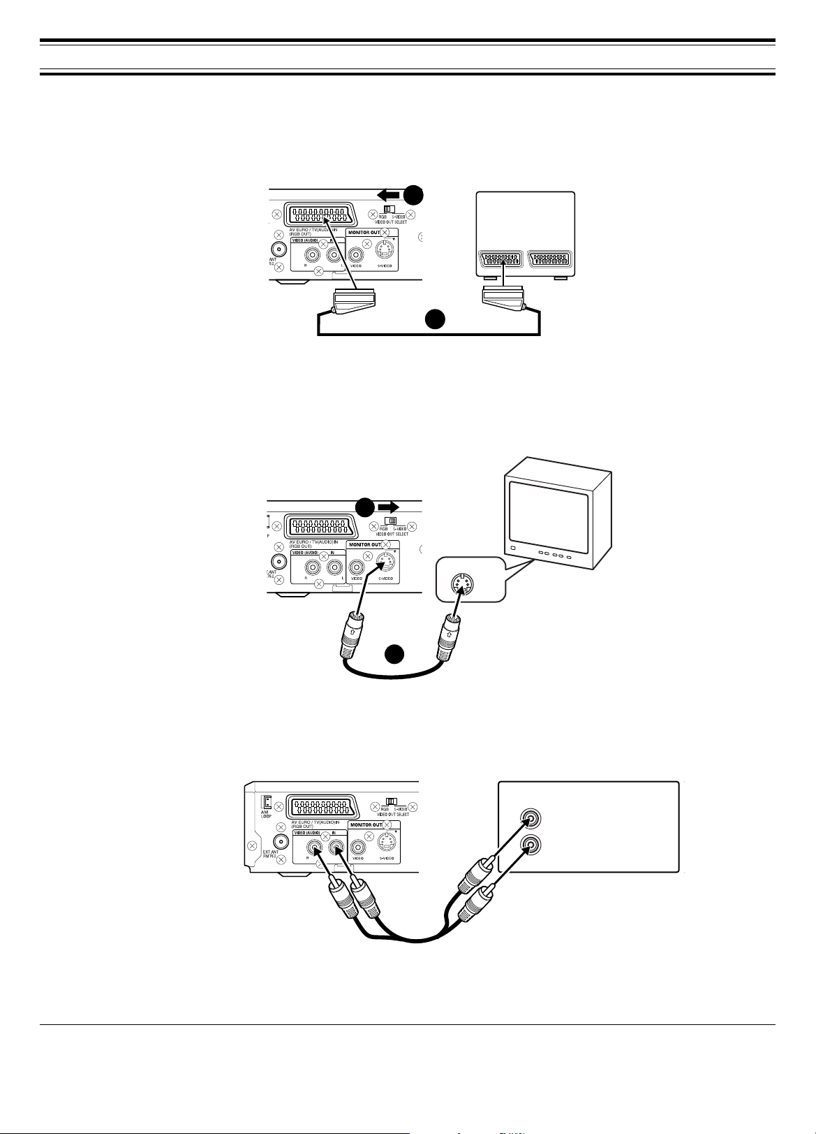
ADDITIONAL CONNECTIONS EXAMPLES
2
1
Connecting to a TV with an EURO-AV/SCART lead
Please follow the steps below before turning on the power.
1. If your TV has an EURO-AV/SCART socket, connect the unit as shown. (Do not connect the video lead to the MONITOR OUT VIDEO socket.) You
can enjoy high quality picture playback.
2. Set the VIDEO OUT SELECT switch to RGB.
JCX-TS760
EURO-AV/SCART lead (not supplied)
TV
EURO-AV/SCART
(RGB input facility)
Connecting to a TV with an S-video lead
Please follow these steps before turning on the power.
1. If your TV has an S-video input socket, connect the unit as shown. (The MONITOR OUT VIDEO socket connection is not necessary.) You can enjoy
clearer picture playback.
2. Set the VIDEO OUT SELECT switch to S-VIDEO.
JCX-TS760
2
S-VIDEO IN 1
TV
1
S-Video lead (not supplied)
TV or Audio equipment connections
Connect an audio lead between the VIDEO (AUDIO) IN sockets of the unit and the audio output sockets of the TV or audio equipment.
JCX-TS760
Audio lead (not supplied)
TV or Audio equipment
(such as MD deck etc.)
AUDIO OUT
L
R
Headphones
Connect stereo headphones (not supplied) to the PHONES socket for monitoring or for private listening. The speakers are automatically disconnected
when headphones are connected.
Manufactured under license from Dolby Laboratories.
“Dolby”, “Pro Logic” and the double-D symbol are trademarks of Dolby Laboratories.
“DTS” and “DTS Digital Surround” are registered trademarks of Digital Theater Systems, Inc.
7
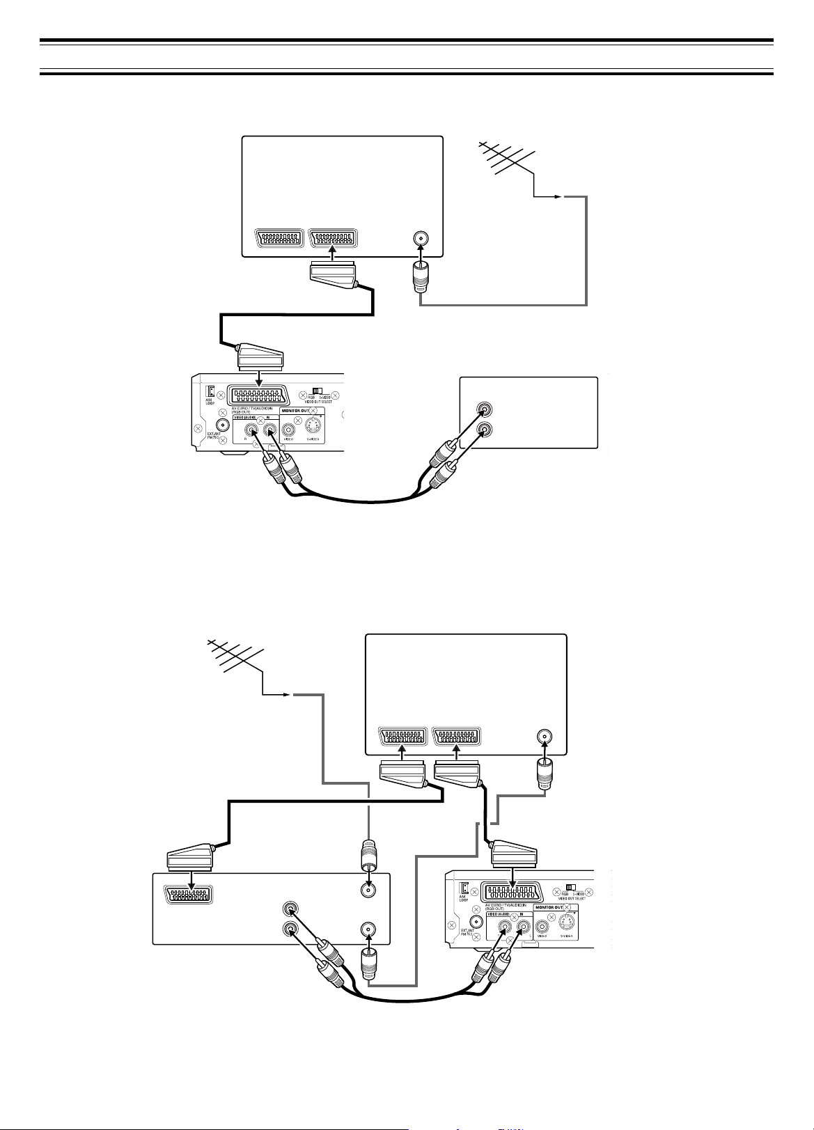
SYSTEM CONNECTIONS EXAMPLES
JCX-TS760, TV and Audio equipment
JCX-TS760
TV
EURO-AV/SCART
(RGB input facility)
EURO-AV/SCART lead (not supplied)
AERIAL
Aerial
IN
Aerial lead (not supplied)
Audio equipment
(such as MD deck etc.)
AUDIO OUT
L
R
Audio lead (not supplied)
JCX-TS760, TV and VCR
EURO-AV/SCART lead
(not supplied)
Aerial
Aerial lead (not supplied)
VCR
AV
AUDIO OUT
L
R
IN
AERIAL
OUT
TV
EURO-AV/SCART
(Audio monitor out)
AERIAL
IN
Aerial lead (not supplied)
EURO-AV/SCART lead (not supplied)
JCX-TS760
Audio lead (not supplied)
8
 Loading...