

Page 1
INSTRUCTION MANUAL
DVD & Hi-Fi VCR Home Theatre System
DC-TS3000
ENGLISH (GB)
Page 2
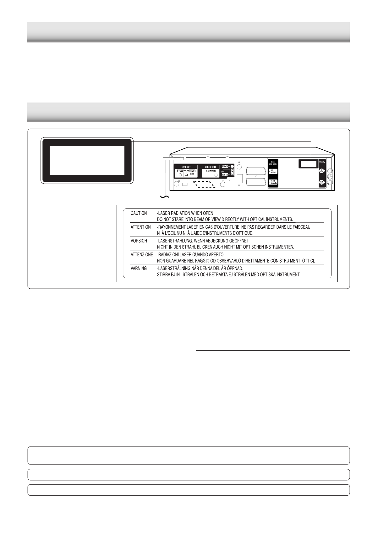
TABLE OF CONTENTS
PRECAUTIONS ....................................2
CONTROLS ..........................................3
REMOTE CONTROL ............................4
BASIC CONNECTIONS........................5
ADDITIONAL CONNECTIONS EXAMPLES..
BEFORE OPERATION ....................... 10
VIDEO CASSETTE TAPE PLAY.........16
CLASS 1 LASER PRODUCT
LUOKAN 1 LASERLAITE
KLASS 1 LASERAPPARAT
RECORDING ...................................... 19
PLAYABLE DISCS ..............................25
DISC PLAY..........................................26
VARIOUS DISC PLAYING FUNCTIONS ...
9
MP3/WMA CD OPERATION ...............33
KODAK PICTURE CD PLAY............... 34
JPEG CD PLAY...................................35
PRECAUTIONS
INITIAL SETTINGS .............................36
LANGUAGE CODE LIST .................... 39
LISTENING TO THE RADIO............... 40
27
TROUBLESHOOTING GUIDE............41
MAINTENANCE .................................. 43
SPECIFICATIONS ..............................44
CLASS 1 LASER PRODUCT
LUOKAN 1 LASERLAITE
KLASS 1 LASERAPPARAT
• The apparatus shall not be exposed to dripping or splashing.
• No objects filled with liquids, such as vases, shall be placed
on the apparatus.
• Do not use where there are extremes of temperature (below
5°C or exceeding 40°C) or where direct sunlight may strike
it.
• Because of the DVD player’s extremely low noise and wide
dynamic range, there might be a tendency to set the volume
on the amplifier unnecessarily high. Doing so may produce
an excessively large output from the amplifier which could
damage your speakers.
• Sudden changes in the ambient temperature may cause
condensation to form on the video head or the optical lens
inside the unit. If this happens, take out the disc, leave the
unit for about 2 hours, and then proceed to operate.
• When carrying the unit, be sure to remove any disc which
may be inside and turn the power off. Wait at least 10
seconds, then unplug the mains lead from the AC outlet.
Carrying the unit with a disc inside may damage the disc
and/or the unit.
• Do not install these equipments in a confined space, such
as a book case or built in cabinet.
CAUTION – USE OF CONTROLS OR ADJUSTMENTS OR PERFORMANCE OF PROCEDURES OTHER THAN THOSE
SPECIFIED HEREIN MAY RESULT IN HAZARDOUS RADIATION EXPOSURE.
This set complies with the EMC Directive 89/336 and with the LVD Directive 73/23.
• Placing the main unit and powered subwoofer in a well
ventilated area is strongly recommended.
Do not place any object on the top of the unit.
Do not block ventilation holes.
The cabinet of the unit warms up when it is used for a long
time, but it is not a malfunction.
NOTES ON COPYRIGHTS:
It is forbidden by law to copy, broadcast, show, broadcast via
cable, play in public, or rent copyrighted material without
permission.
This product features the copy protection function developed
by Macrovision. Copy protection signals are recorded on some
discs. When recording and playing the pictures of these discs
on a VCR, picture noise will appear.
This product incorporates copyright protection technology that
is protected by method claims of certain U.S. patents and other
intellectual property rights owned by Macrovision Corporation
and other rights owners. Use of this copyright protection
technology must be authorized by Macrovision Corporation,
and is intended for home and other limited viewing uses only
unless otherwise authorized by Macrovision Corporation.
Reverse engineering or disassembly is prohibited.
The unit is not disconnected from the mains unless it is unplugged from the AC outlet.
GB-2
Page 3
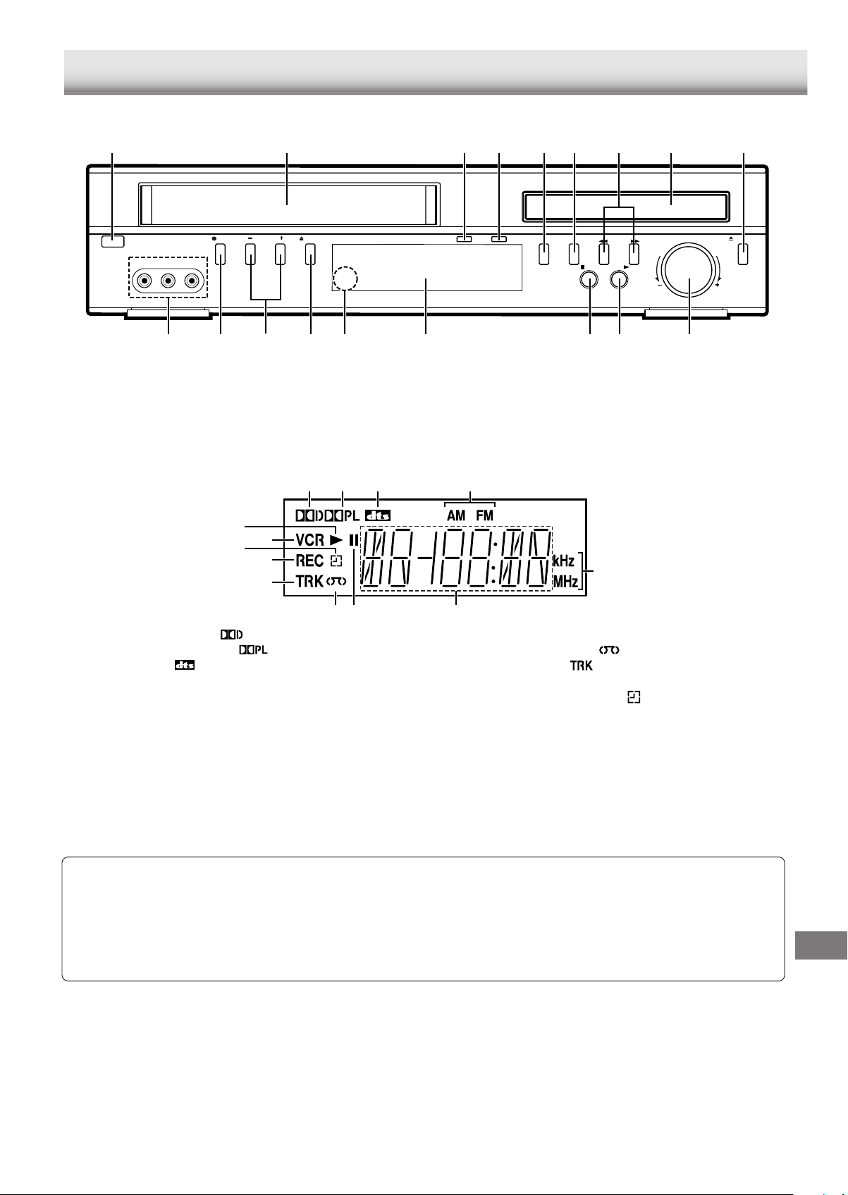
Front panel
1 2 83 4 5 6 79
CONTROLS
POWER
REC
CHANNEL
VIDEO IN L-AUDIO IN-R
1. POWER button
2. Cassette loading slot
3. VCR indicator
4. DVD indicator
5. VCR/DVD mode selector button
6. AM/FM button
EJECT
7. d/c (PRESET +/–) buttons
8. Disc tray
9. OPEN/CLOSE button
10. VOLUME control
11. PLAY button
12. STOP button
Display
13
12
11
10
9
1. Dolby Digital indicator (
2. Dolby Pro Logic indicator ( )
3. DTS indicator ( )
4. AM/FM indicators
5. Kilohertz/Megahertz indicators
6. Message or number indicators
(Title, chapter, track, playing time or other information)
)
312
-
PRESET
AM/FM
VCR/DVD
DVD
VCR
STOP
+
PLAY
11121318 15 141617 10
13. FL display
14. Remote sensor (IR)
15. EJECT button
16. CHANNEL +/– buttons
17. REC button
18. AUDIO (L/R)/VIDEO IN sockets
4
5
678
7. Pause indicator (k)
8. Video tape indicator ( )
9. Track indicator (
10. REC indicator
11. Timer recording indicator ( )
12. VCR indicator
13. Play indicator (a)
)
VOLUME
OPEN/CLOSE
Notes:
• “DTS” and “DTS Digital Out” are trademarks of Digital Theater Systems, Inc.
• DVD video discs with DTS may not work correctly. You can see the picture on the TV screen, but there is no sound.
• Manufactured under license from Dolby Laboratories.
• “Dolby”, “Pro Logic” and the double-D symbol are trademarks of Dolby Laboratories.
ACCESSORIES
RB-TS3000STXE remote control
R03/AAA battery x 2
AM loop aerial
FM aerial wire
Aerial lead
Front right speaker lead (Black and Red)
Front left speaker lead (Black and White)
Centre speaker lead (Black and Green)
Surround right speaker lead (Black and Gray)
Surround left speaker lead (Black and Blue)
Subwoofer lead (Din 9-pin lead)
GB-3
Page 4
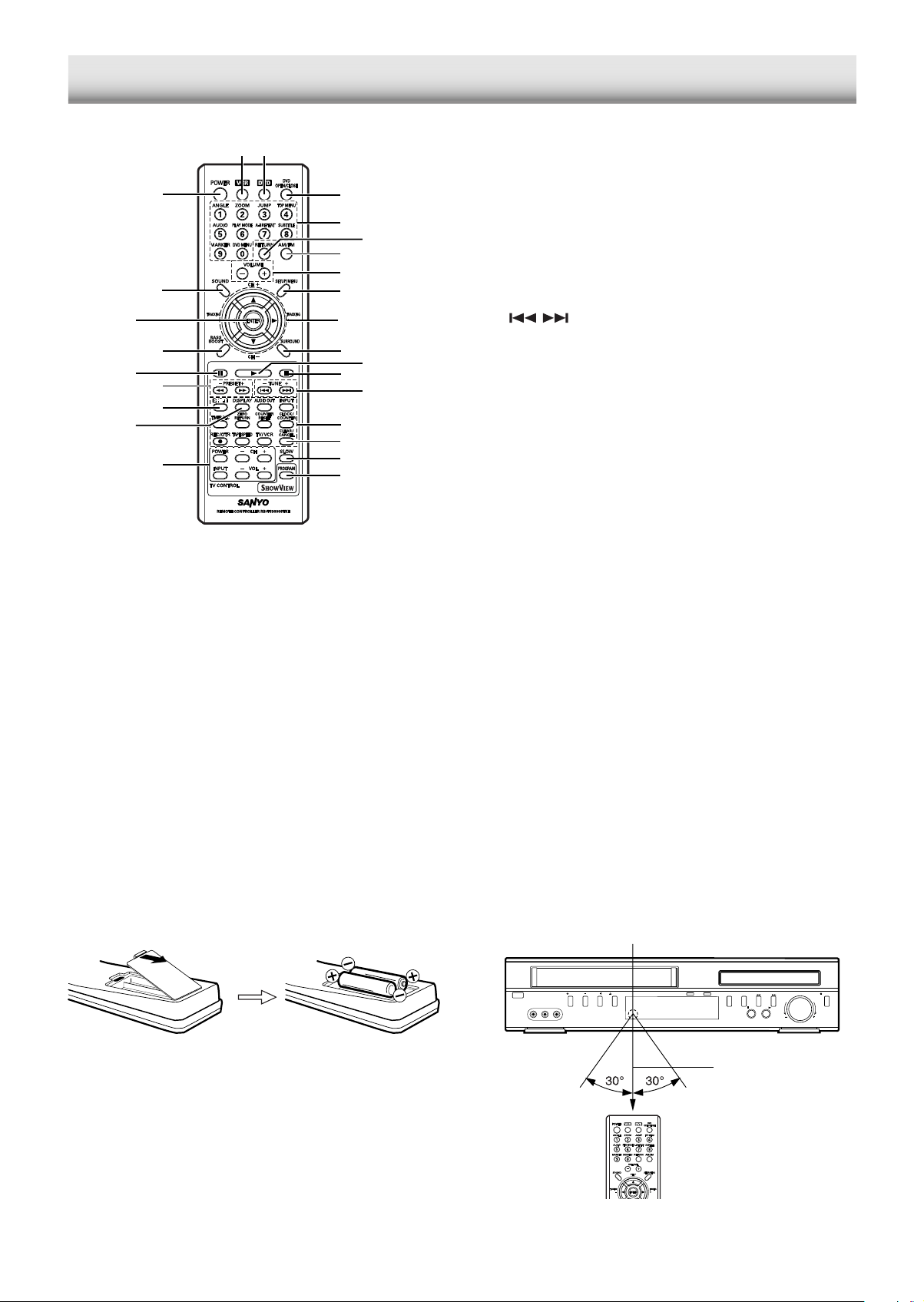
REMOTE CONTROL
Controls
2 3
1
26
25
24
23
22
21
20
19
1. POWER button
2. VCR button
3. DVD button
4. DVD OPEN/CLOSE button
5. Number and other function buttons
These buttons are used as number buttons and as function
buttons of each name.
• When using as a number button, press the appropriate
button directly.
Number buttons (1–9, 0)
• When using as a function button of each name, press the
appropriate button while holding [SHIFT] down.
ANGLE button
ZOOM button
JUMP button
TOP MENU button
AUDIO button
PLAY MODE button
A-B REPEAT button
SUBTITLE button
MARKER button
DVD MENU button
4
5
7
8
9
10
11
13
15
16
17
18
6
12
14
6. RETURN button
7. AM/FM button
8. VOLUME +/– buttons
9. SETUP/MENU button
10. Directional arrow buttons (4, a, 5, b)
CH (Channel) +/– buttons
TRACKING +/– buttons
11. SURROUND button
12. Play button (a)
13. Stop button ( n)
14.
/ buttons
TUNE (Tuning) +/– buttons
15. VCR control buttons
AUDIO OUT button
INPUT button
TIMER REC button
ZERO RETURN button
COUNTER RESET button
CLOCK/COUNTER button
REC/OTR (Recording/One-touch Timer Recording) button
TAPE SPEED button
TV/VCR button
16. CLEAR/CANCEL button
17. SLOW button
18. PROGRAM button
19. TV control buttons
Notes:
• Only SANYO TVs can be operated using this remote
control.
• There may be some TV models that cannot be operated
with this remote control. If this is the case, use the
original remote control supplied with the TV.
POWER button
INPUT select button
CH (Channel) scanning +/– buttons
VOL (Volume) +/– buttons
20. DISPLAY button
21. SHIFT button
22. d /c buttons
PRESET tuning +/– buttons
23. Pause button (k)
24. BASS BOOST button
25. ENTER button
26. SOUND button
Inserting batteries
Install two “R03/AAA” batteries.
Note:
Remove the batteries if the remote control is not to be used for
a month or more. Batteries left in the unit may leak and cause
damage.
GB-4
Remote control range
Remote sensor
POWER
VIDEO IN L-AUDIO IN-R
EJECT
REC
CHANNEL
-
PRESET
+
AM/FM
VCR/DVD
STOP
PLAY
Within approx.
7 meters
VOLUME
OPEN/CLOSE
Page 5
BASIC CONNECTIONS
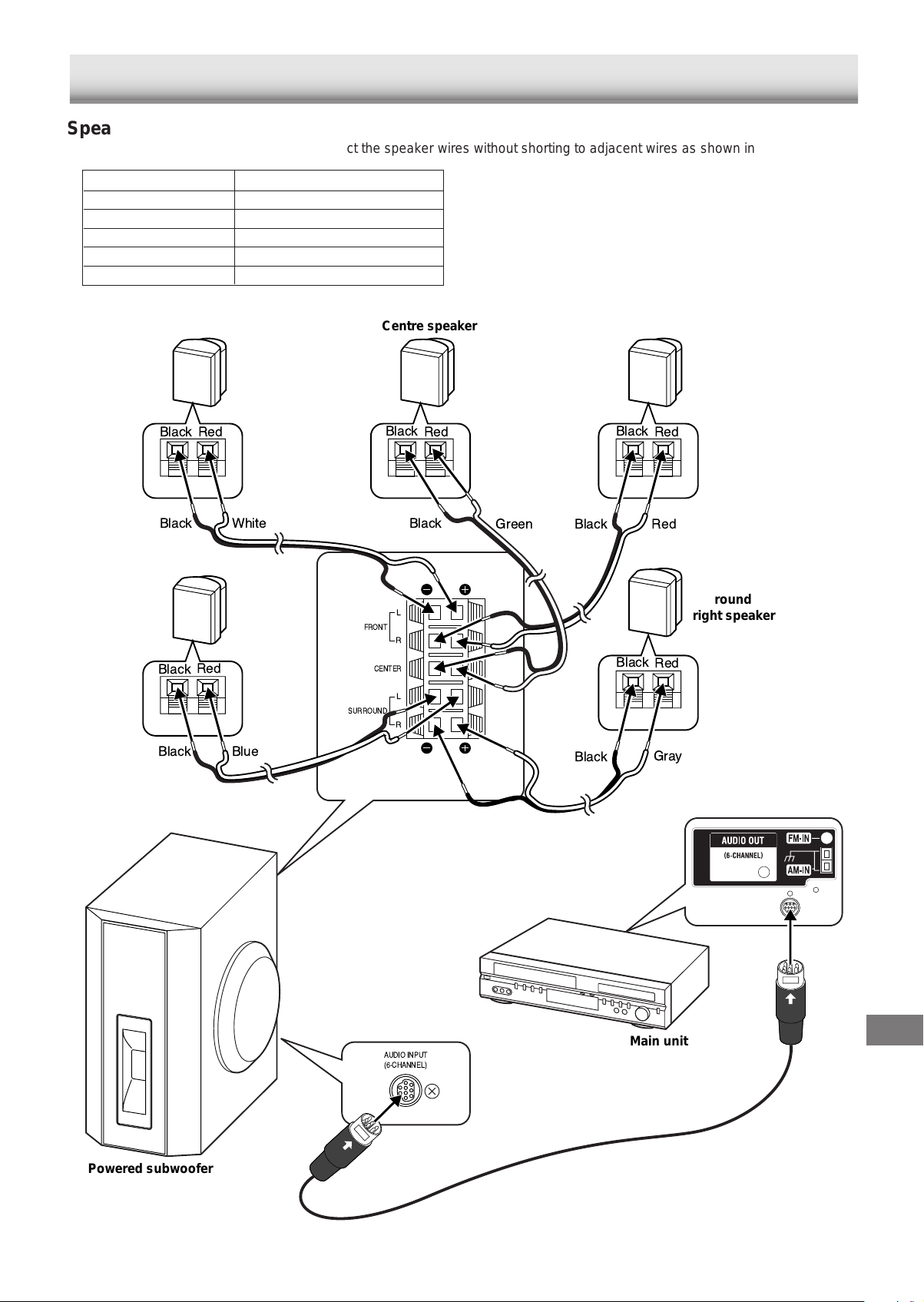
Speaker connections
To achieve proper stereo reproduction, connect the speaker wires without shorting to adjacent wires as shown in figure.
Speaker wire colour Use
Black and White Front left speaker
Black and Red Front right speaker
Black and Green Centre speaker
Black and Blue Surround left speaker
Black and Gray Surround right speaker
Front left speaker
Red
Black
Black
White
Surround
left speaker
Black
Red
FRONT
SURROUND
Centre speaker
Black
Red
Black
L
R
CENTER
L
R
Note:
The SPEAKERS sockets are designed for use only with the
supplied speakers. Do not use with other speakers. Connecting
other speaker may damage the speaker and/or the unit.
Front right speaker
Black
Red
Green
RedBlack
Surround
right speaker
Black
Red
Black
Powered subwoofer
Blue
AUDIO INPUT
(6-CHANNEL)
Black
Gray
Main unit
GB-5
Page 6
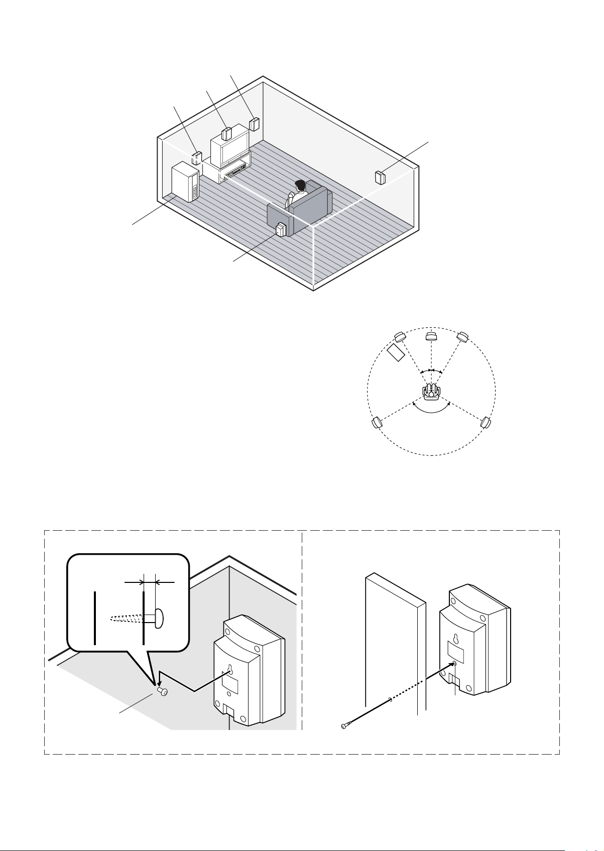
Speaker placement
Centre speaker
Front left speaker
Powered subwoofer
Place it near the Front speaker.
Front right speaker
Surround right speaker
Surround left speaker
The supplied satellite speakers have built-in magnetic stray
field compensation. They may be placed close to a TV without
affecting the colour purity.
The five speakers are all the same and can be used for Front
left, Centre, Front right, Surround left, and Surround right
speakers.
The front, centre, and surround speakers should be placed at
approximately the same distance from the listening position.
Place the front left and right speakers either side of the TV.
Place the centre speaker directly above the TV.
Place the surround speakers either sides of the listening position,
or slightly to the rear, approximately 60 cm ~ 1 meter higher
than ear level.
The powered subwoofer can be placed near the front speaker
and not too far from the TV.
Example: To hang the speaker on a wall Example: To mount the speaker with a stand
Approximately 2.5 mm
Front left speaker Front right speaker
Powered
subwoofer
Surround left
speaker
Notes:
• The angles in the diagram are approximate.
• Please see to “Changing the delay time” on page 11.
• Set the TV’s built-in speaker volume to minimum.
Stand (not supplied)
Centre speaker
30°30°
120°
Surround right
speaker
Built-in special nut, 3/16 inch
Round head screw
(not supplied)
Note: Take care when installing the speakers. They may cause damage or serious injury should they fall from their mountings.
Screw
(not supplied)
diameter
GB-6
Page 7
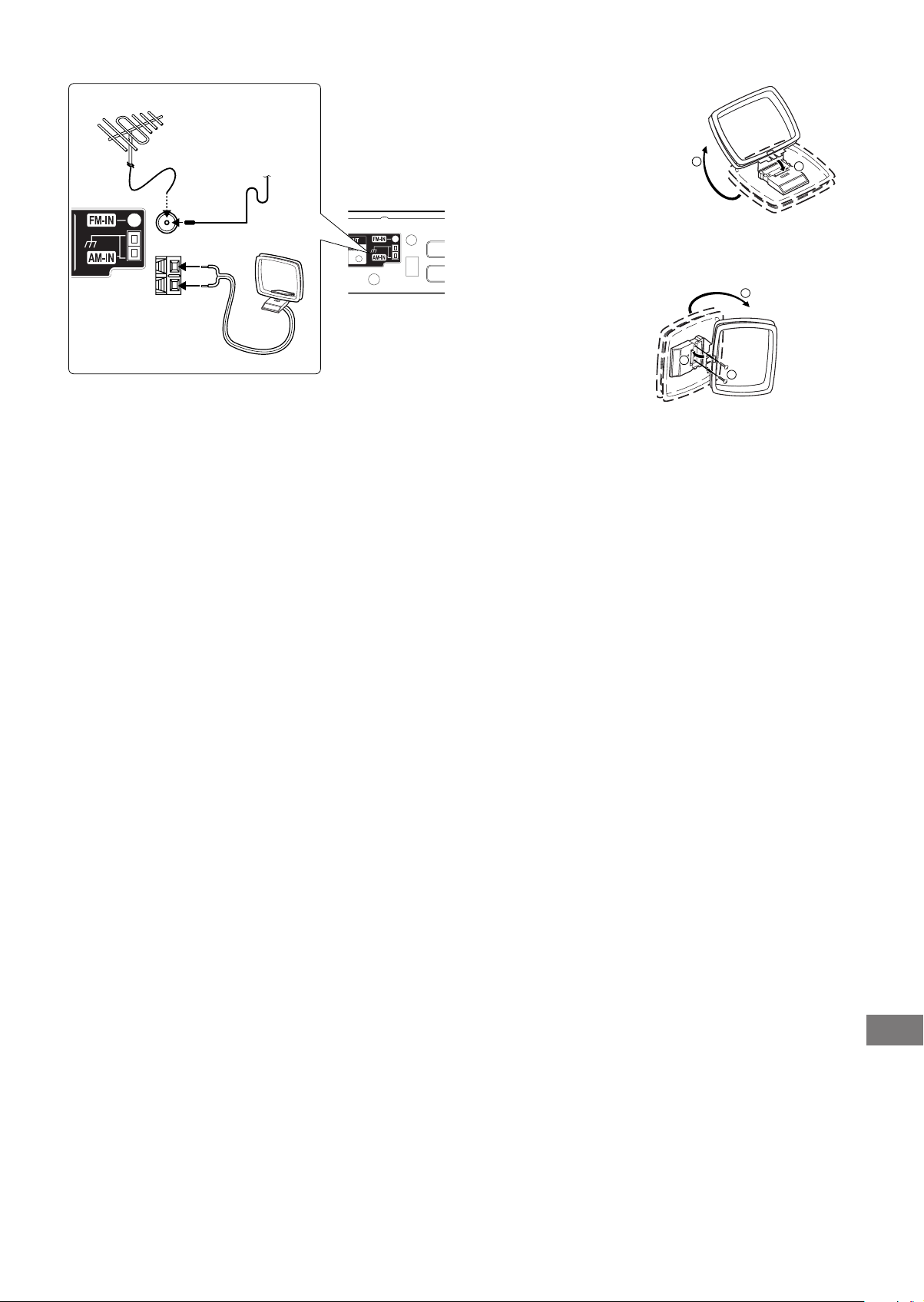
AM loop aerial
FM external aerial
Aerial wire
Black
White
AM/FM aerial connections
AM loop aerial
Assemble the loop aerial.
1
2
JCX-TS3000
Unwind the aerial wires, then connect them to the AM-IN
terminals. Place the loop aerial in a position which yields the
best AM reception, or attach it to a wall or other surface.
1
In areas close to a transmitter the simple indoor aerial is
sufficient to receive broadcasts. Extend the aerial wire as
straight as possible and, while listening to the sound from the
system, secure it in a position which yields minimal distortion
and noise.
In fringe areas or where reception is distorted or noisy, an FM
3
Note:
To minimize noise, the speaker, mains and any other leads
should not come close to the indoor or external aerial lead and
AM loop aerial. Do not place the aerial leads close to the
system.
2
Screws (not supplied)
external aerial (not supplied) should be connected instead of
the simple indoor aerial. Consult your dealer.
Notes on connections:
• Please refer to the instruction manuals for the components that you are connecting (TV, VCR, etc.).
• When you connect the unit to your TV and other equipment, be sure to turn off the power and disconnect all of the equipments
from the AC outlet until all the connections have been made.
• Please consult your local audio/video dealer for more details.
GB-7
Page 8
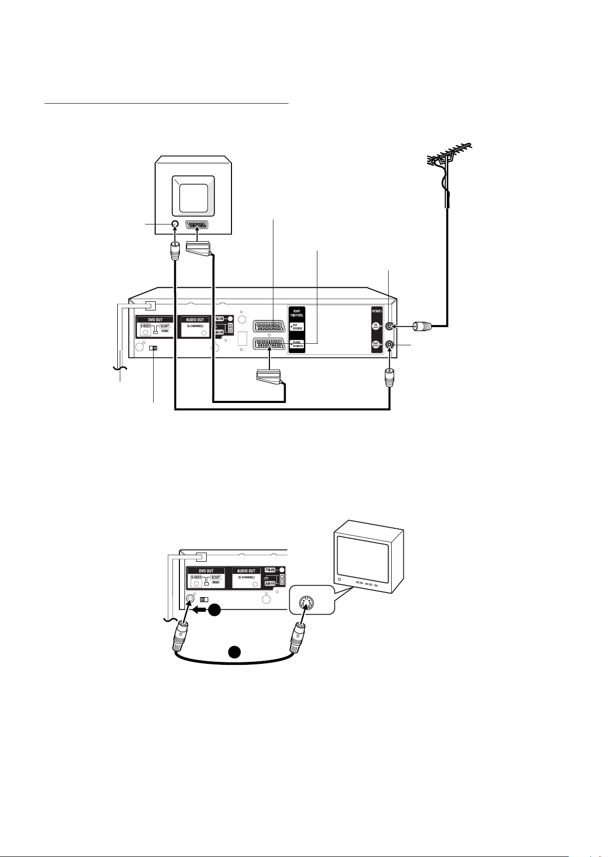
TV aerial and TV connections
You can connect the unit to a TV using Aerial or SCART leads.
In addition to the aerial lead connection, connect also with scart lead. The picture and sound will be transmitted best through the
scart lead. In this case, the TV need not be tuned to the video recorder. The Video channel also need not be tuned. The video
recorder switch the television to video operation through the scart lead automatically.
The stereo-play is possible in only case through a scart lead!
Note:
When you play the DVD/CD disc, set the DVD OUT selector to SCART (RGB).
TV
Aerial
VCR/DECODER
Scart socket (AV2)
RF Input
TV-RGB/Composite
To Scart
socket
JCX-TS3000
Scart socket (AV1)
RF-Input
Aerial lead
(not supplied)
RF-Output
Mains lead
DVD OUT selector
Scart lead
(not supplied)
Aerial lead (supplied)
Connecting to a TV with an S-video lead
Note:
You can ONLY watch DVD play through the connections shown below.
Please follow these steps before turning on the power.
1. If your TV has an S-video input socket, connect the unit as shown. You can enjoy clearer picture play.
2. Set the DVD OUT selector to S-VIDEO.
JCX-TS3000
S-VIDEO IN 1
TV
2
1
S-video lead (not supplied)
Mains supply (Main unit and Powered subwoofer)
After all connections have been made, connect the mains lead to an AC outlet.
The powered subwoofer will automatically turn on when the main unit is turned on.
Note:
Do not connect the mains lead to an AC outlet until all connections have been made.
GB-8
Page 9
SYSTEM SETUP
CLOCK SET
AV2 [DEC]
LANGUAGE/SPRACHE/LANGUE
LINGUA/LENGUA
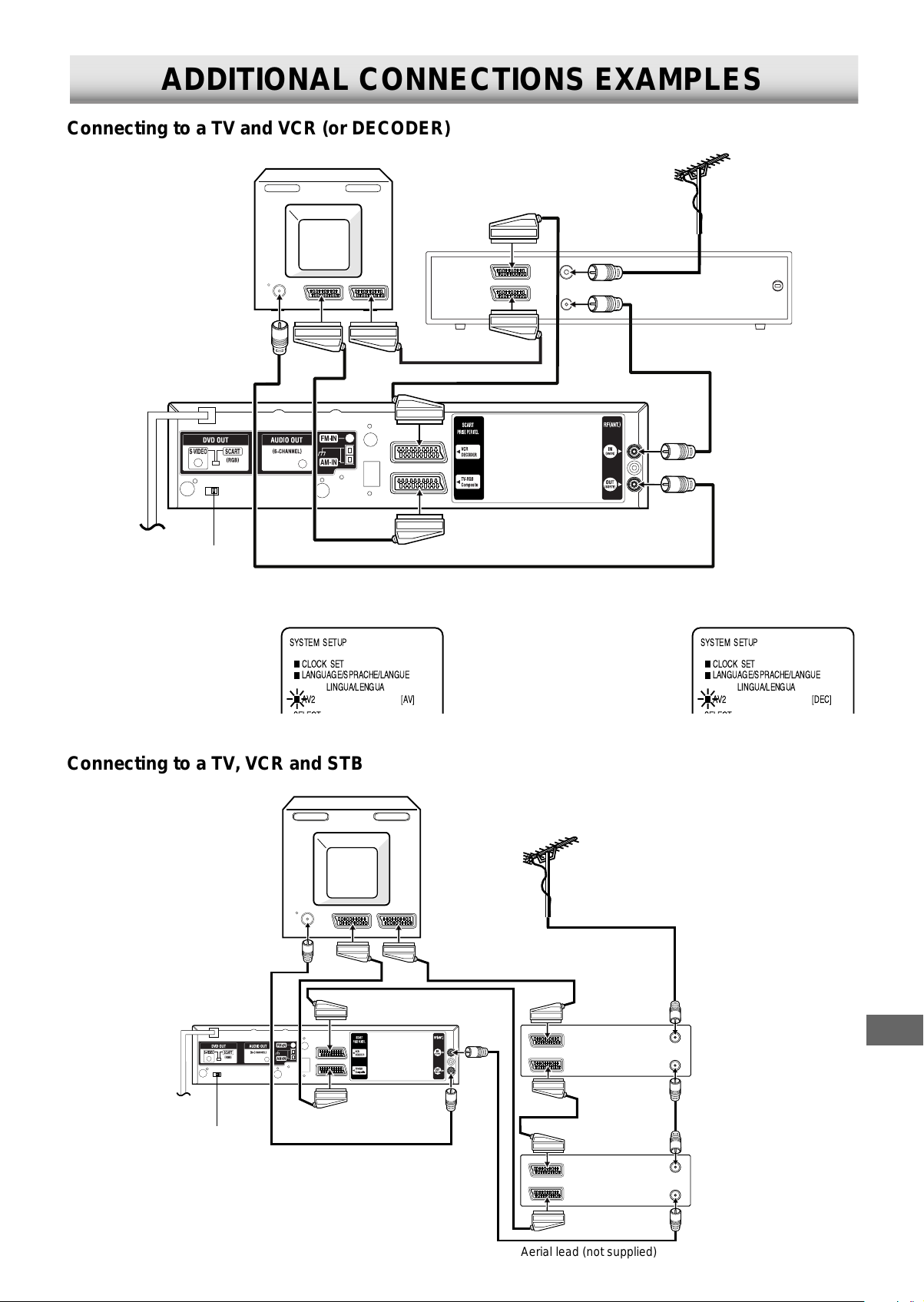
ADDITIONAL CONNECTIONS EXAMPLES
Connecting to a TV and VCR (or DECODER)
TV
Aerial
IN/OUT
AV
IN/OUT
Scart lead (not supplied)
JCX-TS3000
DVD OUT selector
Scart lead (not supplied)
Scart lead (not supplied)
Aerial lead (supplied)
Note: Make sure the AV2 selection in SYSTEM SETUP menu is set correctly.
• When you connect to another
VCR, select “AV”.
SYSTEM SETUP
CLOCK SET
LANGUAGE/SPRACHE/LANGUE
LINGUA/LENGUA
AV2 [AV]
• When you connect to the
decoder, select “DEC”.
OUT
IN
AERIAL
Aerial lead
(not supplied)
VCR (or DECODER)
Aerial lead
(not supplied)
Connecting to a TV, VCR and STB
TV
JCX-TS3000
Scart lead
DVD OUT selector
(not supplied)
Aerial lead (supplied)
Scart lead (not supplied)
Scart lead (not supplied)
Aerial
Aerial lead (not supplied)
Set Top Box
IN/OUT
AV
IN/OUT
IN
AERIAL
OUT
Scart lead
(not supplied)
VCR
IN/OUT
AV
IN/OUT
IN
AERIAL
OUT
Aerial lead
(not supplied)
Aerial lead (not supplied)
GB-9
Page 10

BEFORE OPERATION
This instruction manual explains the various functions of this unit using the remote control.
The buttons on the main unit perform similar functions to similarly marked buttons on the remote control.
Common operation
Turning the power on and off
Press [POWER] to turn the power on. (After connecting the
mains lead, when you press [POWER] for the first time, the
volume-reset feature automatically sets the initial volume level.)
When the mains lead is connected to the AC outlet, the unit will
respond to commands from the remote control.
To turn the power off, press [POWER] again.
Selecting the function
Press [VCR] to select the “VCR” function.
Press [DVD] to select the “DVD” function.
Press [AM/FM] to select the “Tuner” function.
Press [INPUT] repeatedly in the “VCR” function to select the
external source or original source.
Notes:
• When the source is selected the “DVD” or “Tuner” function,
you cannot use [INPUT] button.
• When the source selection is changed to the “Tuner”
function, disc and tape play automatically stops.
Front panel operation
Press [VCR/DVD] repeatedly to select the “VCR” or “DVD”
function.
Press [AM/FM] to select the “Tuner” function.
Adjusting the volume
Press [VOLUME] + or – (or rotate [VOLUME] on the front
panel). The volume level appears on the FL display (Vol 0 ~ Vol
40).
Note:
Set the TV’s built-in speaker volume to minimum.
Adjusting the sound mode and speaker level
1. Press [SOUND].
“BA” appears on the FL display.
2. Press [ENTER] repeatedly to select the desired sound
mode.
Each time [ENTER] is pressed, the sound mode changes
as follows:
v
BA (Bass)
FL (Front left speaker) v C (Centre speaker)
FR (Front right speaker) v SR (Surround right speaker)
SL (Surround left speaker) v SU (Subwoofer) v . . .
3. Press [4] or [5] to adjust the sound level.
BA/TR: “+5” ~ “–5”
Q: “Lo” or “HI”
FL/FR: “0” ~ “–10”
C/SR/SL/SU: “+10” ~ “–10”
4. Repeat steps 2 ~ 3 for another sound mode.
• You can also use the menu screen to adjust the speaker
level. See “Adjusting the speaker and subwoofer level”
on page 11.
TR (Treble) v Q (Q-Surround)
Bass boost system
Press [BASS BOOST].
“BA” appears on the FL display.
Press the button repeatedly to select the bass boost effect ON
or OFF.
BA ON v BA OFF v BA ON . . .
v
v
v
Selecting surround mode
Press [SURROUND] button to select the surround mode.
“AUTO” appears on the FL display. Each time the button is
pressed, the surround mode changes as follows:
AUTO v 2Q 5.1 v 1Q 5.1 v 2 ch . . .
When “DVD” function is selected
AUTO
The unit selects the surround mode automatically depending
on the disc.
• If a DVD disc is encoded with Dolby Digital, “ s D”
appears on the FL display, and it is played back with
Dolby Digital 5.1 channel surround sound.
Not all DVD discs are encoded with Dolby Digital 5.1
channel surround sound.
• If a DVD disc is encoded with Dolby Digital 2-channel or
mono, both “ s D” and “ s PL” appear on the FL
display. The surround mode is set to Dolby Pro Logic
mode.
• If a DVD disc is encoded with 2-channel Liner PCM,
“ s PL” appears on the FL display. The surround mode
is set to Dolby Pro Logic mode.
• VCD, Audio CD, MP3 and WMA discs are played back
with Q-Surround 5.1 channel surround sound.
2Q 5.1
Disc is played back with Q-Surround 5.1 channel surround
sound.
For 2-channel source, it uses Virtual 5.1 channel surround
sound.
1Q 5.1
When using a monaural source, select this mode. It uses
Virtual 5.1 channel surround sound.
2 ch
The surround mode is set to 2.1 channel (Front left and
right speakers, and Subwoofer).
When “VCR” or “AM/FM” function is selected
AUTO
The surround mode is set to Q-Surround 5.1 channel
surround sound.
2Q 5.1
The surround mode is set to Q-Surround 5.1 channel
surround sound.
For 2-channel source, it uses Virtual 5.1 channel surround
sound.
1Q 5.1
When using a monaural source, select this mode. It uses
Virtual 5.1 channel surround sound.
2 ch
The surround mode is set to 2.1 channel (Front left and
right speakers, and Subwoofer).
Notes:
• DVD video discs with DTS may not work correctly. You can
see the picture on the TV screen, but there is no sound.
• When receiving weak FM broadcasts, set the mode to “2
ch”.
The sound quality may improve.
GB-10
Page 11
Adjusting the speaker volume balance
This unit is set to the standard level before shipping from the
factory. You may not need adjustment.
But, depending on the size of the room and the placement of
the speakers, you may benefit from a fine adjustment.
In this case, follow the steps below. Please use the remote
control at the listening point.
1. Press [SETUP/MENU].
When the unit is in DVD mode and in the Stop mode or disc
is not inserted, press [SETUP/MENU] twice.
The “MENU” screen appears on the TV screen.
2. Press [4] or [5] to select “SPEAKER SETUP”, then press
[ENTER].
The “SPEAKER SETUP” screen appears.
SPEAKER SETUP
VOL. ADJUST
DELAY ADJUST
3. Press [ENTER].
The “VOL. ADJUST” screen appears.
4. Press [4] or [5] to select “TEST TONE”, then press
[ENTER].
5. The test tone will be heard from each speaker for 2 seconds
in the following order.
VOL. ADJUST
FÐL
CENTRE FÐR
SURR.L VOL. Ð 0 SURR.R
TRIM
TEST TONE
TV screen Speaker
F-L Front left Speaker
CENTRE Centre Speaker
F-R Front right Speaker
SURR.R
SURR.L
Surround right Speaker
Surround left Speaker
6. Press [VOLUME] + or – until the test tone is at a comfortable
level.
7. If the test tone level is not the same from each speaker,
press [4] or [5] to adjust it while the speaker is activating.
F-L/F-R: “0” ~ “–10”
CENTRE/SURR.R/SURR.L: “+10” ~ “–10”
8. Repeat steps 6 ~ 7 for other settings.
9. Press [SETUP/MENU] until the menu screen is cleared.
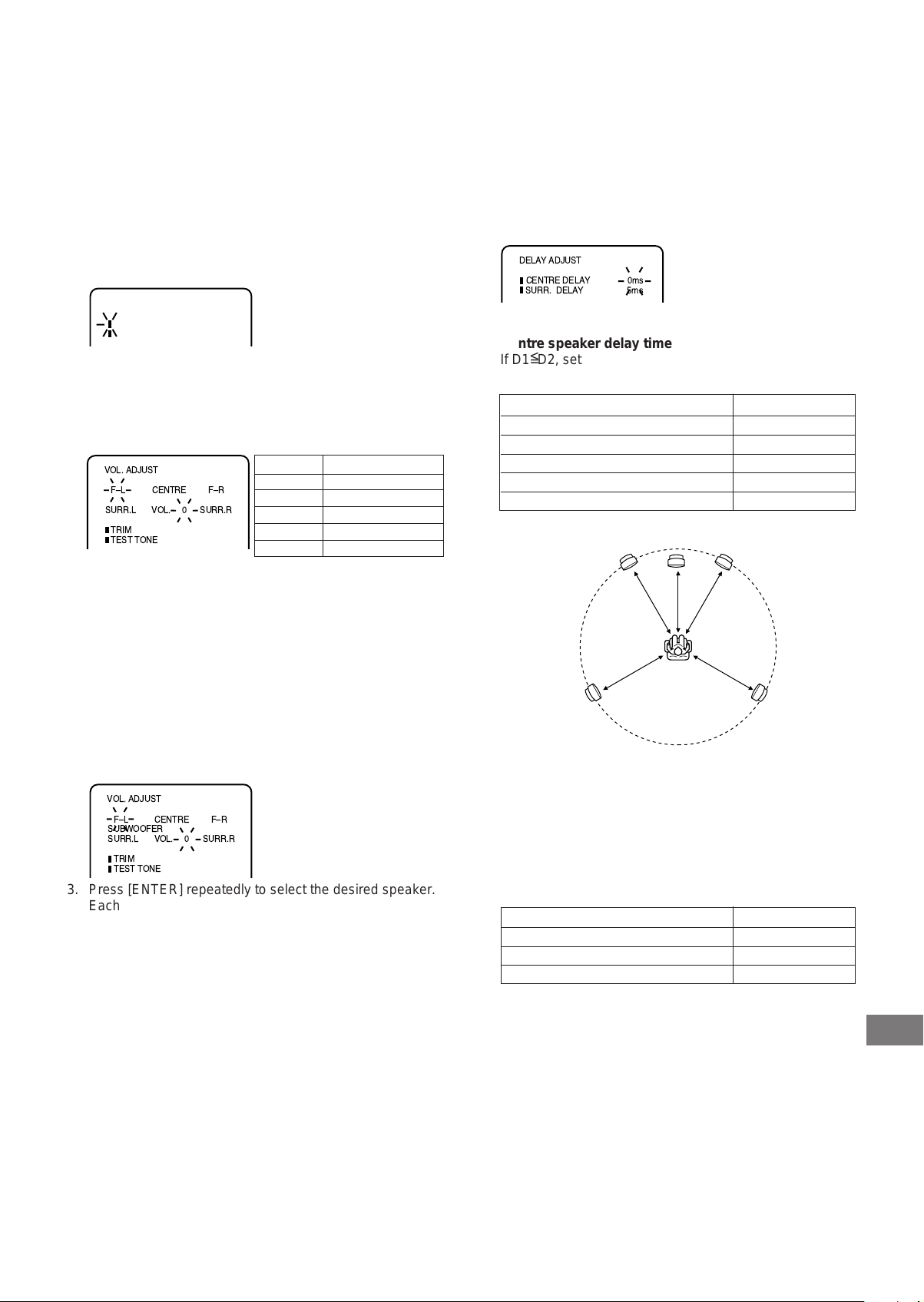
Adjusting the speaker and subwoofer level
1. Follow steps 1 ~ 3 above.
2. Press [4] or [5] to select “TRIM”, then press [ENTER].
VOL. ADJUST
FÐL
TRIM
TEST TONE
CENTRE FÐR
VOL. Ð 0 SURR.R
SUBWOOFER
SURR.L
3. Press [ENTER] repeatedly to select the desired speaker.
Each time the button is pressed, the selected speaker and
tone level blink.
4. Press [4] or [5] to adjust the level as desired.
F-L/F-R: “0” ~ “–10”
CENTRE/SURR.R/SURR.L/SUBWOOFER: “+10” ~ “–10”
Note: No test tone.
5. Repeat steps 3 ~ 4 for other settings.
6. Press [SETUP/MENU] until the menu screen is cleared.
Note:
If no adjustment are made, the original display returns after
approximately 60 seconds.
Changing the delay time
The sound from speakers can reach the listening position at
different times depending the speaker placements. You can
allow for this difference by changing the delay time of the
centre and surround speakers.
1. Follow steps 1 ~ 2 left.
2. Press [4] or [5] to select “DELAY ADJUST”, then press
[ENTER].
The “DELAY ADJUST” screen appears.
3. Press [4] or [5] to select “CENTRE DELAY”, then press
[ENTER].
DELAY ADJUST
CENTRE DELAY 0ms
SURR. DELAY 5ms
4. Press [4] or [5] to select the centre speaker delay time.
Centre speaker delay time
<
If D1
D2, set the delay time to “0ms”.
=
If D1>D2, set the delay time as follows:
Difference between D1 and D2 Delay time
Approx. 30cm 1ms
Approx. 60cm 2ms
Approx. 90cm 3ms
Approx. 120cm 4ms
Approx. 150cm 5ms
Centre speaker
Front left speaker Front right speaker
D2
D1
Surround left
speaker
5. Press [ENTER].
“CENTRE DELAY” and the selected delay time remain.
6. Press [4] or [5] to select “SURR. DELAY”, then press
[ENTER].
7. Press [4] or [5] to select the surround speaker delay time.
Surround speaker delay time
<
If D1
D3, set the delay time to “0ms”.
=
If D1>D3, set the delay time as follows:
Difference between D1 and D3 Delay time
Approx. 150cm 5ms
Approx. 300cm 10ms
Approx. 450cm 15ms
8. Press [ENTER].
“SURR. DELAY” and the selected delay time remain.
9. Press [SETUP/MENU] until the menu screen is cleared.
Note:
If no adjustments are made, the original display returns after
approximately 60 seconds.
D1
D3D3
Surround
right speaker
GB-11
Page 12
Setting the VCR channel
VCR
SP
VCR
SP
If you have connected the unit to your TV using an aerial lead
only, tune your TV as follows.
Preparation:
• Make sure that the unit is connected properly to the TV.
• Turn on the TV and select the channel you wish to allocate
for video use.
1. Press and hold [POWER] on the front of the unit in the
Standby mode until “rF” and RF output channel “36” will
appear on the FL display.
2. Tune the TV in the same way as tuning in a TV broadcast
station until the word “TEST” blinks on the TV screen. Refer
to the TV operating instructions for tuning.
Now the output from the unit is tuned to this channel.
Whenever you want to play back a tape, select this channel.
TEST
3. If there is interference in the picture (wavy lines, picture
roll, etc.), press [CHANNEL] +/– on the front panel to select
any RF channel between 23 and 69, retuning your TV until
the word “TEST” blinks on the TV screen.
If you have connected the unit to your TV using an aerial
lead and a scart lead, press [CHANNEL] +/– repeatedly
until “OFF” appears on the FL display (“OFF” will appear
after 69 or before 23).
4. Press [POWER] to turn OFF the unit.
Now the TV is tuned to the unit.
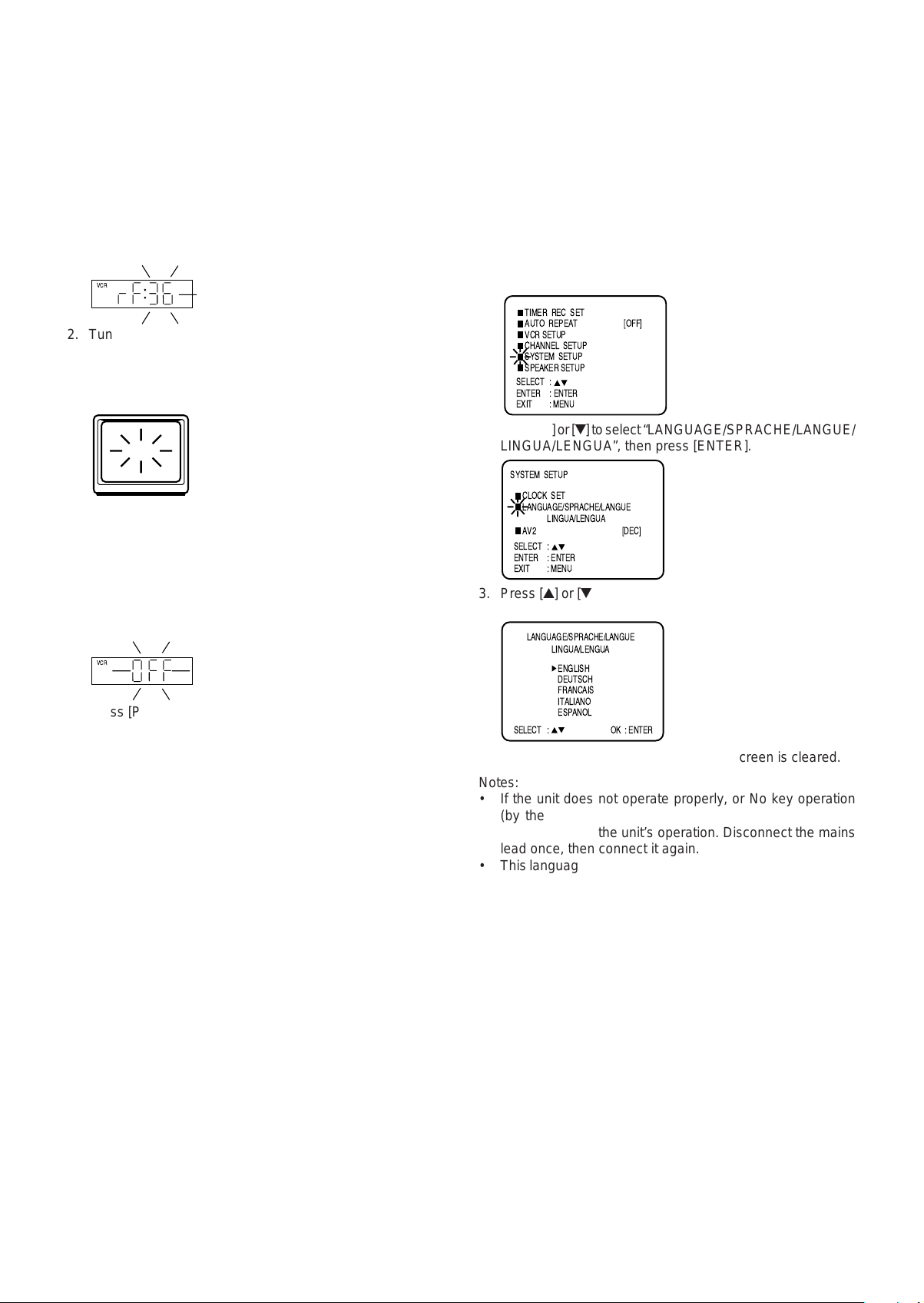
On-screen language selection
You can choose from five different languages (English, German,
French, Italian and Spanish) for the on screen displays.
In this instruction manual, the language in on-screen display is
English. If you changed the language, please follow the selected
language in on-screen display.
Preparation:
• Press [POWER] to turn on the unit.
• Press [VCR] to select the VCR mode. (The VCR indicator
will light.)
1. Press [SETUP/MENU]. Press [4] or [5] to select “SYSTEM
SETUP”, then press [ENTER].
TIMER REC SET
AUTO REPEAT [OFF]
VCR SETUP
CHANNEL SETUP
SYSTEM SETUP
SPEAKER SETUP
SELECT :
ENTER : ENTER
EXIT : MENU
2. Press [4] or [5] to select “LANGUAGE/SPRACHE/LANGUE/
LINGUA/LENGUA”, then press [ENTER].
SYSTEM SETUP
CLOCK SET
LANGUAGE/SPRACHE/LANGUE
LINGUA/LENGUA
AV2 [DEC]
SELECT :
ENTER : ENTER
EXIT : MENU
3. Press [4] or [5] to select the desired language, then press
[ENTER].
LANGUAGE/SPRACHE/LANGUE
LINGUA/LENGUA
ENGLISH
DEUTSCH
FRANCAIS
ITALIANO
ESPANOL
SELECT : OK : ENTER
• The first time you press
[SETUP/MENU], the left
LANGUAGE menu will
appear.
Note:
If you want to change the RF output channel or switch to “OFF”,
press and hold [POWER] on the front panel in the Standby
mode until the current RF output channel appears. Press
[CHANNEL] +/– to select the RF channel you desire.
4. Press [SETUP/MENU] until the menu screen is cleared.
Notes:
• If the unit does not operate properly, or No key operation
(by the unit and/or the remote control): Static electricity,
etc., may affect the unit’s operation. Disconnect the mains
lead once, then connect it again.
• This language selection is not effective for DVD operations.
GB-12
Page 13

Setting the time and date
This unit is fitted with a 24-hour clock.
You must set the date and time for timer recordings.
Automatic tuning
This feature automatically searches and tunes all available TV
stations and preset them up to 80 different stations (if available).
Example: Setting the clock to 11:30, 25 Oct. 2003.
1. Press [SETUP/MENU]. Press [4] or [5] to select “SYSTEM
SETUP”, then press [ENTER].
• The step-2 will appear when clock is not set.
TIMER REC SET
AUTO REPEAT [OFF]
VCR SETUP
CHANNEL SETUP
SYSTEM SETUP
SPEAKER SETUP
SELECT :
ENTER : ENTER
EXIT : MENU
2. Press [4] or [5] to select “CLOCK SET”, then press [ENTER].
SYSTEM SETUP
CLOCK SET
LANGUAGE/SPRACHE/LANGUE
LINGUA/LENGUA
AV2 [DEC]
SELECT :
ENTER : ENTER
EXIT : MENU
3. Press [b] or [a] repeatedly until “25” appears. Then press
[5] to continue.
CLOCK SET
DAY
MONTH
YEAR
TIME
SELECT :
SET : / 0Ð9
OK : ENTER
25 SAT
1
2003
0:00
EXIT : MENU
4. Set the month, year, hour and minute in the same way as in
step 3. Then press [ENTER]. The clock will begin operation.
CLOCK SET
DAY
MONTH
YEAR
TIME
SELECT :
SET : / 0Ð9
OK : ENTER
25 SAT
10
2003
11:30
EXIT : MENU
• In case of an error, press [4] to go back to one step and
enter again.
5. Press [SETUP/MENU] until the menu screen is cleared.
Notes:
• If you want to correct the setting, follow steps 1 ~ 2 above,
press [4] or [5] to select the item then press [b] or [a] to
correct to the desired setting.
• In case of a power failure, the clock will continue to operate
for another 30 minutes with quartz-controlled precision. To
indicate that the power failure has lasted for an excessive
period of time “--:--” will appear on the display. In this case
readjust time and date.
1. Press [SETUP/MENU]. Press [4] or [5] to select “CHANNEL
SETUP”, then press [ENTER].
TIMER REC SET
AUTO REPEAT [OFF]
VCR SETUP
CHANNEL SETUP
SYSTEM SETUP
SPEAKER SETUP
SELECT :
ENTER : ENTER
EXIT : MENU
2. Press [4] or [5] to select “AUTO TUNING”.
CHANNEL SETUP
CH TUNING
AUTO TUNING
CHANNEL MAPPING
SELECT :
ENTER : ENTER
EXIT : MENU
3. Press [ENTER].
The unit is now automatically tuning in all available TV
stations (VHF-L,VHF-H and UHF). While tuning channels,
“AUTO TUNING” blinks. After the tuning finished, the
“CHANNEL MAPPING” menu will appear.
CHANNEL MAPPING
AUTO TUNING
1
2
3
4
SELECT : /
SKIP : CANCEL
CHANGE NAME : 1
MOVE : 2
EXIT : MENU
5
6
7
8
9
10
11
12
• You can enter the TV station name or move TV station
positions using CHANNEL MAPPING menu. (See page
14.)
4. Press [SETUP/MENU] until the menu screen is cleared.
To skip unwanted TV station
Unwanted channels can be skipped so that they cannot be
called up by pressing [CH] +/–. Select the channel you want to
skip, then press [CLEAR/CANCEL]. The channel number will
be blinking on the FL display. That way you can cancel further
channel one after the other.
• To cancel skipping, select the desired skipped channel using
the number buttons [0–9], then press [CLEAR/CANCEL].
The channel now may be selected using [CH] +/–.
• You can also skip unwanted channels using CHANNEL
MAPPING menu. (See page 15.)
Notes:
• TV reception interference or power failure may result in
Automatic tuning malfunctions. In such a case repeat the
setting procedure from the beginning.
• If the Automatic tuning could not tune the necessary TV
station, try to tune the TV station manually. (See page 15.)
• When the unit is in the auxiliary input mode, you cannot
select “AUTO TUNING” in the CHANNEL SETUP menu.
GB-13
Page 14
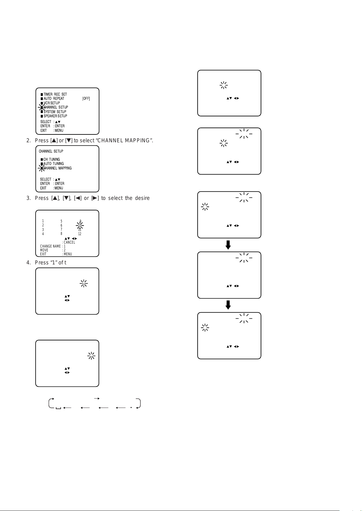
Mapping TV stations
You can enter or change the respective names for the TV
stations by yourself.
Entering TV station name
Example: The TV station (MTV) is preset to channel position
10, but there is no station name on the table.
1. Press [SETUP/MENU]. Press [4] or [5] to select “CHANNEL
SETUP”, then press [ENTER].
TIMER REC SET
AUTO REPEAT [OFF]
VCR SETUP
CHANNEL SETUP
SYSTEM SETUP
SPEAKER SETUP
SELECT :
ENTER : ENTER
EXIT : MENU
2. Press [4] or [5] to select “CHANNEL MAPPING”.
CHANNEL SETUP
CH TUNING
AUTO TUNING
CHANNEL MAPPING
SELECT :
ENTER : ENTER
EXIT : MENU
3. Press [4], [5], [b] or [a] to select the desired channel
position.
CHANNEL MAPPING
1
2
3
4
SELECT : /
SKIP : CANCEL
CHANGE NAME : 1
MOVE : 2
EXIT : MENU
5
6
7
8
9
10
11
12
4. Press “1” of the number buttons [0–9].
CHANGE BROADCAST NAME
1
2
3
4
SELECT :
NAME :
OK : ENTER
CLEAR : CANCEL
EXIT : MENU
5
6
7
8
9
10
11
12
5. Press [4] or [5] repeatedly until the desired character
appears, then press [a] to enter the next character...
After entering a station name, press [ENTER].
CHANGE BROADCAST NAME
1
2
3
4
SELECT :
NAME :
OK : ENTER
CLEAR : CANCEL
EXIT : MENU
5
6
7
8
9
10 MTV
11
12
• Each press of [4] will change the character as follows.
A, B, C, ... X, Y, Z 0, 1, 2, ... 7, 8, 9
—+ /
6. Repeat steps 3 ~ 5 above to enter another station name.
7. Press [SETUP/MENU] until the menu screen is cleared.
Note:
When a wrong character is entered, press [CLEAR/CANCEL]
and enter the correct character.
• To go to next or previous
page, press [b] or [a].
• Up to four characters can
be used to create a station
name.
Moving TV station positions
Example: Move the TV station (BR3) under No. 6 to position
No. 2.
1. Repeat the steps 1 ~ 2 as left, then press [ENTER].
2. Press [4], [5], [b] or [a] to select the desired channel
position.
CHANNEL MAPPING
1 ARD
2 ZDF
3 RTL
4 SAT1
SELECT : /
SKIP : CANCEL
CHANGE NAME : 1
MOVE : 2
EXIT : MENU
5 PRO 7
6 BR3
7 SW3
8 N3
9 HR3
10 WDR3
11 MDR3
12 TM3
3. Press “2” of the number buttons [0–9].
MOVE CHANNEL 6 BR3
1 ARD
2 ZDF
3 RTL
4 SAT1
POSITION : /
MOVE : ENTER
EXIT : MENU
5 PRO 7
6
7 SW3
8 N3
9 HR3
10 WDR3
11 MDR3
12 TM3
4. Press [4], [5], [b] or [a] to select the desired channel
position to be moved, then press [ENTER].
MOVE CHANNEL 6 BR3
1 ARD
2 ZDF
3 RTL
4 SAT1
POSITION : /
MOVE : ENTER
EXIT : MENU
MOVE CHANNEL WAIT
1 ARD
2 ZDF
3 RTL
4 SAT1
POSITION : /
MOVE : ENTER
EXIT : MENU
MOVE CHANNEL 6 ZDF
1 ARD
2 BR3
3 RTL
4 SAT1
POSITION : /
MOVE : ENTER
EXIT : MENU
5 PRO 7
6
7 SW3
8 N3
5 PRO 7
6
7 SW3
8 N3
5 PRO 7
6
7 SW3
8 N3
9 HR3
10 WDR3
11 MDR3
12 TM3
9 HR3
10 WDR3
11 MDR3
12 TM3
9 HR3
10 WDR3
11 MDR3
12 TM3
Note:
If you press [SETUP/MENU] or any button is not pressed
for more than 60 seconds, this station (ZDF) will be set to
this position number (6) automatically.
5. Repeat step 4 above to move another TV station position.
6. Press [SETUP/MENU] until the menu screen is cleared.
• To go to next or previous
page, press [b] or [a].
• The TV station (BR3) will
be moved to the first line.
• “WAIT” blinks for approx.
12 seconds.
• Now the station BR3 is
set in new position 2.
• The TV station (ZDF) will
be moved to the first line.
GB-14
Page 15

Skipping unwanted TV stations
1. Repeat the steps 1 ~ 2 in “Entering TV station name” on
page 14, then press [ENTER].
2. Press [4], [5], [b] or [a] to select the desired channel
position.
CHANNEL MAPPING
1 ARD
2 ZDF
3 RTL
4 SAT1
SELECT : /
SKIP : CANCEL
CHANGE NAME : 1
MOVE : 2
EXIT : MENU
5 PRO 7
6 BR3
7 SW3
8 N3
9 HR3
10 WDR3
11 MDR3
12 TM3
3. Press [CLEAR/CANCEL].
CHANNEL MAPPING
1 ARD
2 ZDF
3 RTL
4 SAT1
SELECT : /
SKIP : CANCEL
CHANGE NAME : 1
MOVE : 2
EXIT : MENU
5 PRO 7
6 BR3
7 SW3
8 N3
9 HR3
10 WDR3
11 MDR3
[12] TM3
• The number before the
skipped TV station name
(e.g. 12) will be bracketed.
4. Press [SETUP/MENU] until the menu screen is cleared.
To unskip a channel:
Press [4], [5], [b] or [a] to select the desired channel position
on the step 2 above, then press [CLEAR/CANCEL]. The bracket
will disappear.
Manual tuning
In certain areas of the countries which have poor reception the
Automatic tuning may not tune your unit to the strongest
broadcast signal. If you are not satisfied with the automatic
tuning you may manually tune your unit to obtain the best
possible picture and sound.
Example: Preset the TV station (SAT1) on channel position 5.
1. Press [SETUP/MENU]. Press [4] or [5] to select “CHANNEL
SETUP”, then press [ENTER].
4. Press [b] (falling frequency) or [a] (rising frequency) once
to start the search. It stops at each broadcast automatically
(“a” change to “k”). Press [b] or [a] repeatedly until the
SAT1 appears, then press [ENTER].
DEC OFF
SEARCH : / F. TUNE :
EXIT : MENU
CH 1
DEC OFF
SEARCH : / F. TUNE :
OK : ENTER EXIT : MENU
CH 1
• If you need to make the picture clearer, press [4] or [5]
for Fine tuning.
5. Press [4] or [5] repeatedly until “5” is displayed. Or enter
[5] with the number buttons [0–9]. Then press [ENTER].
CH 5
DEC OFF
CH : / 0Ð9
OK : ENTER EXIT : MENU
6. Repeat the steps 3 ~ 5 to preset other TV stations.
7. Press [SETUP/MENU] until the menu screen is cleared.
Note:
Occasionally, the auto search might catch a weak signal and
stop. If the TV station signal is weak, you shouldn't store this
station. In that case restart the auto search using [b] or [a].
TIMER REC SET
AUTO REPEAT [OFF]
VCR SETUP
CHANNEL SETUP
SYSTEM SETUP
SPEAKER SETUP
SELECT :
ENTER : ENTER
EXIT : MENU
2. Press [4] or [5] to select “CH TUNING”, then press [ENTER].
CHANNEL SETUP
CH TUNING
AUTO TUNING
CHANNEL MAPPING
SELECT :
ENTER : ENTER
EXIT : MENU
3. When the decoder is not connected with the unit.
Press [ENTER] to select “DEC OFF”.
CH 1
DEC OFF
SELECT :
OK : ENTER EXIT : MENU
When the decoder is connected with the unit.
Press [b] or [a] to select “DEC ON”, then press [ENTER].
Important Information:
TV, DVD, Video CD, Audio CD, MP3 CD, WMA CD or VHS
recorded materials are not same Audio output level. You
must adjust the volume level individually.
GB-15
Page 16

VIDEO CASSETTE TAPE PLAY
Loading and unloading a cassette tape
Use only video cassette tapes marked and .
• Cassettes marked “VHS” (or “S-VHS”) can be used with
this video cassette recorder. However, S-VHS recording is
not possible with this model.
• This model is equipped with SQPB (S-VHS QUASI
PLAYBACK) that makes it possible to play back S-VHS
recordings with regular VHS resolution.
• HQ VHS is compatible with existing VHS equipment.
• SQPB play can be seen only at PAL SP mode.
Loading
Push the centre of the tape until it is automatically inserted.
Insert the cassette tape with its labeled side facing up and the
erase prevention tab positioned at your left. An inverted cassette
tape cannot be inserted.
Erase prevention tab
Automatic power ON
When you insert a cassette tape, the unit power will turn ON
automatically.
Unloading
1. Press [q EJECT] on the front panel. Even if a tape is being
played, press this button only once.
To prevent accidental erasure
Remove the erase prevention tab with a screwdriver.
Screwdriver
Erase prevention tab
To record again
Cover the hole with a piece of adhesive tape.
Adhesive tape
Adjusting tracking condition
Automatic tracking adjustment
Whenever you insert a tape and start play, automatic tracking
starts working and continuously analyzes the signal to enable
optimum picture quality during play.
Manual tracking adjustment
If automatic tracking cannot eliminate noises well during play,
press [TRACKING] +/– to eliminate the noises. “MANUAL TR.”
will appear. Press it briefly for a fine adjustment, or press and
hold for a coarse adjustment.
To return to automatic tracking, eject the tape and play again.
Notes:
• The audio output is muted during SPEED SEARCH, STILL,
FRAME ADVANCE and SLOW MOTION.
• During picture search mode there will be noise bars which
are caused by the system.
• The Special play will automatically change to play after
approx. 5 minutes to protect the video tape against excessive
wear.
2. Remove the cassette tape.
Automatic tape eject
This unit will automatically rewind the tape when the tape has
ended. And when the tape is rewinded to its beginning, the
cassette tape will be ejected automatically.
GB-16
Page 17

Cassette tape play
Preparation:
• Turn on the TV, and select the VCR channel on TV.
• Press [VCR] to select the VCR mode. (The VCR indicator
will light.)
1. Load a prerecorded tape. (When
loading a cassette tape without the
erase prevention tab, play will start
automatically.)
2. Press [a (Play)]. Play will start.
To stop play
Press [n].
To rewind the tape or forward it rapidly
Stop the play or recording with [n].
To rewind the tape: Press [d].
Special play
Picture search
Reverse picture search function
Press [d] x 1 or x 2 during the play.
Forward picture search function
Press [c] x 1 or x 2 during the play.
To return to play: Press [a (Play)].
Still picture
Press [k] during play.
To resume normal play: Press [a (Play)].
Slow motion
During play, press [SLOW].
You can change the slow speed by the additional pressing of
[SLOW].
1/5 v 1/10 v1/30
To return to play: Press [a (Play)].
Slow tracking and vertical lock adjustment
If noise bars appear in the picture during slow motion, press the
[TRACKING] +/– to reduce the noise bars.
If the still picture jitters excessively, press [TRACKING] +/– to
stabilize the still picture.
Frame by frame picture
During play, press [k] one by one: The picture advances frame
by frame.
To return to play: Press [a (Play)].
To forward the tape: Press [c].
To stop the tape-winding, press [n]. To switch to play directly
(without stop), press [a (Play)].
Forward/reverse picture search mode
When the tape is being winded, you can switch to picture
search mode (see right). To do this, press [d] or [c] and
hold it down. The unit will resume the tape winding as soon as
the button is released.
NTSC video cassette play
When using a pre-recorded NTSC video cassette tape, the
connected TV set must operate with a 60 Hz vertical frequency.
Otherwise the on-screen picture will be affected by vertical
rolling. Even if your VCR set is capable of processing NTSC
video signals, the picture may be shortened vertically
(appearance of black bars at the top and at the bottom of the
TV screen). The dubbing of a NTSC video cassette tape to a
standard PAL VCR is not possible.
Notes:
• This VCR selects the play tape speed SP or LP
automatically.
• The cassette tape and DVD disc can be played back
simultaneously. If you press [VCR] or [DVD], the tape play
and DVD play alternate with each other on the screen.
Repeat play
If the Repeat function is switched on, the play will continue until
it reaches the tape-end and then rewind to the beginning of the
tape. This process will repeat until the unit is turned off.
1. Press [SETUP/MENU]. Press [4] or [5] to select “AUTO
REPEAT”.
TIMER REC SET
AUTO REPEAT [OFF]
VCR SETUP
CHANNEL SETUP
2. Press [b], [a] or [ENTER] to select “ON” or “OFF”.
TIMER REC SET
AUTO REPEAT [ ON ]
VCR SETUP
CHANNEL SETUP
3. Press [SETUP/MENU] until the menu screen is cleared.
If “ON” has been selected, the tape will be repeatedly
played.
Note:
To cancel the auto repeat mode, follow the steps 1 and 2
above, then press [b], [a] or [ENTER] to select “OFF”.
GB-17
Page 18

ZERO RETURN function
This function makes tape-rewinding stop at the counter “00:00:00”
position automatically.
1. Press [DISPLAY].
The counter display shows the tape running time during
play or recording.
12:00 SUN
Video index search system
This function enables you to locate the beginning of any
recording made on the VCR.
Recording an INDEX mark
The Index search function automatically records an INDEX
mark on the tape whenever a recording is initiated.
CH 2
00:04:38 SP
2. Press [COUNTER RESET] at the desired tape position.
The counter display will be reset to the “00:00:00” position
(e.g. the beginning of recording).
12:00 SUN
00:00:00 SP
3. Press [n] when play or recording is finished.
4. Press [ZERO RETURN].
The tape will be rewinded or fast forwarded and automatically
stop at the “00:00:00” position.
5. Press [DISPLAY] once again to make all the indicator
disappear.
The CLOCK/COUNTER button
Press [CLOCK/COUNTER] during the play. The clock and tape
counter alternate with each other on the FL display.
Notes:
• You can set the tape counter to “00:00:00” with [COUNTER
RESET] anytime. Therefore, the counter display can also
indicate “00:00:00”, even when the tape counter does not
reach its beginning yet. Even if the tape counter indicates
“00:00:00”, it can be rewinded moreover. If the tape was
rewinded over the point of “00:00:00”, the minus mark “–”
appears in the counter display. Although the tape counter
seems to forward when you press [d], in fact the tape is
being rewinded. When the tape reaches the beginning, the
tape-rewinding stops automatically.
• When you load a video cassette, the display indication
changes to “00:00:00”.
• The counter display does not function on non-recorded
(blank) sections of the tape. When you rewind, fast forward
or play tapes through blank sections, the counter display
stops.
INDEX
Index search
Press [ ] or [ ] during stop or play mode.
For Succeeding programmes: Press [ ].
For Preceding programmes: Press [ ].
(Additional press increases the INDEX NO. up to 9.)
When [ ] or [ ] is pressed, the unit starts searching the
INDEX NO. selected and finds the portion, then play starts
automatically. To stop the Index search, press [n].
or
is displayed
INDEX NO. (up to 9)
Notes:
• When you record an INDEX mark at the very beginning of
the tape, the mark may not be found.
• During INDEX search, the tape may stop and begin to play
at a slightly different location.
• INDEX search may not function properly with old or worn out
video tapes.
• INDEX marks may not be found if it is extremely close to the
point where the search began.
• In recording, if you stop recording temporarily, the INDEX
mark is not recorded on the tape.
To display VCR operation status
Press [DISPLAY]. The clock, day of the week and more
informations will be indicated.
To cancel the indicating: Press [DISPLAY] again.
Example:
Indication for
Hi-Fi play
stereo reception
or
Day of the week
Time
23:59 MON
HI-FI
STEREO
01:36:58 SP
Deck-status
here: Play
CH 80
****
Programme
number or
Scart input
AV1/AV2/AV3
*
Station's name
(e.g. ZDF)
Cassette in
Unit
GB-18
Audio select
Tape speed
Stand of Tape counter
Page 19

RECORDING
Recording a TV programme
Preparation:
• Turn on the TV, and select the VCR channel on TV.
• Press [VCR] to select the VCR mode. (The VCR indicator
will light.)
1. Load a blank cassette tape with the erase prevention tab
intact.
2. Select the programme (e.g.29) you want to record with [CH]
+/– or the number buttons [0–9].
1~9 : e.g. 5 = press “5”
10~80 : e.g. 29 = press “2” and “9”.
3. If a recording in Long Play mode is intended, press [TAPE
SPEED] to display “LP”.
4. Press [REC/OTR].
“m” will appear on the screen for about 4 seconds and
“REC” will appear on the FL display.
If the erase prevention tab is removed, the tape will eject
when [REC/OTR] is pressed for recording.
CH 29
One-touch timer recording (OTR)
The one-touch timer recording feature provides a simple and
convenient way to make a timed recording.
1. Follow steps 1 ~ 3 left.
2. Press [REC/OTR] to begin recording. Press [REC/OTR]
again to stop recording after 30 minutes. Each additional
press of [REC/OTR] will increase recording time as shown
in the chart below, up to a maximum of 6 hours. The OTR
and recording time will appear on the screen for about 4
seconds.
OTR 0:30
CH 29
6:00
To extend the recording time
Press [REC/OTR] repeatedly until the desired time appears.
OTR 1:30
CH 29
To stop the OTR
Press [n].
1:30Recording 0:30 1:00
2:005:00 4:00 3:00
To stop recording
Press [n].
To stop recording temporarily
To stop a recording for a short period of time, press [k]. Press
this button again if you want to resume the recording.
Attention:
A safety circuit turns the pause mode off automatically after 5
minutes, and the VCR will stop the recording mode.
Notes:
• Since the unit has a built-in TV tuner, the TV set may be
turned off when recording. The TV set may only be used to
check for accurate programme adjustments or to monitor
recordings.
• You can confirm on the TV-screen whether you selected SP
or LP. Press [DISPLAY] to see the status display.
• If you wish to watch the DVD play during the normal
recording on VCR, press [DVD] to change to DVD mode
and perform the DVD play.
Notes:
• If you wish to watch the DVD play during the OTR, press
[DVD] to change to DVD mode and perform the DVD play.
• If the tape supply has not sufficed for OTR recording, the
clock symbol (
In this case, press [TIMER REC] to cancel the blink, then
press [q EJECT] on the front panel to remove the cassette
tape.
) will blink at the tape-end.
Auto rewind feature
The VCR will automatically rewind when the tape has ended
(except during OTR and TIMER REC). It will also eject the
cassette tape.
GB-19
Page 20

SHOWVIEW® recording
Look up the SHOWVIEW number codes in an appropriate TV
programme magazine. Select the desired TV programme for
recording and refer to the number code next to it.
Preparation:
Load a video cassette with the erase prevention tab intact.
Make sure that the time and date are correct.
1. Press [PROGRAM].
SHOWVIEW NO.
ONCE
DAILY
SHOWVIEW
SELECT
CLEAR
OK
EXIT
2. Enter the SHOWVIEW code using the number buttons [0–9].
SHOWVIEW
SELECT
CLEAR
OK
EXIT
• In case of an error, press [CLEAR/CANCEL] and enter
3. Press [4] or [5] to select ONCE, DAILY or WEEKLY.
ONCE: To record a programme only once
DAILY: To record TV programmes transmitted daily
WEEKLY:
4. Press [ENTER]. By the SHOWVIEW code, the entered data
appears on the screen. Then press [b], [a] or the number
buttons [0–9] to enter CH number, then press [5].
SELECT :
SET : / 0Ð9
EXIT : MENU
• If the entered Number is not correct, the indicator
• Only in case of the TV station that you decode for the
WEEKLY
: 0Ð9
NO.
:
: CANCEL
: ENTER
: SHOWVIEW
SHOWVIEW NO. 57378
ONCE
DAILY
WEEKLY
: 0Ð9
NO.
:
: CANCEL
: ENTER
: SHOWVIEW
the desired number again.
To record TV programmes transmitted once a
week.
SHOWVIEW NO. 57378
DATE 15 FRI
START 17:00
END 18:00
CH
SPEED SP
--
OK : ENTER
“SHOWVIEW NO. ERROR” will appear. Enter the correct
number.
first time, the “– –” will blink at the CH line. That is to say,
you must enter the corresponding channel position with
the decoded TV station manually.
Example:
You receive TV station (TM3) on CH position 12.
In case of the first SHOWVIEW-recording for TM3, “– –”
will blink at the CH line. Enter [1] and [2] with the number
buttons [0–9] within 2 seconds. The SHOWVIEW-system
memorizes that the storing position 12 is for TM3. From
the next all times of the SHOWVIEW-recording from TM3,
“12” will be entered in the CH line automatically.
SHOWVIEW NO.
DATE 15 FRI
START 17:00
END 18:00
CH 12
SPEED SP
SELECT :
SET : / 0Ð9
EXIT : MENU
57378
OK : ENTER
Setting the day of the week:
If you have selected Daily or Weekly, then you can select a
recording date again. The DATE must blink.
If it does not blink, then press [4] or [5] repeatedly until the
DATE blinks. Then press [b] or [a] repeatedly until the
desired date appears. The following date options are
available:
SUN-SAT: Sunday to Saturday
MON-SAT: Monday to Saturday
MON-FRI: Monday to Friday
WKL-MON: each Monday
WKL-TUE: each Tuesday
…
…
WKL-SUN: each Sunday
Recording period extension:
The recording end time will be set by SHOWVIEW
automatically. However you can extend the recording end
time manually. The time END must blink.
If it does not blink, then press [4] or [5] repeatedly until the
time end blinks. Then press [a] to extend.
5. Press [4] or [5] repeatedly until the SPEED blinks. Then
press [b] or [a] to select “SP” or “LP”.
SHOWVIEW NO. 57378
DATE 15 FRI
START 17:00
END 18:00
CH 12
SPEED SP
SELECT :
SET :
EXIT : MENU
• If you want to correct the setting, press [4] or [5] to
select the item then press [b] or [a] to correct to the
desired setting.
6. Press [ENTER] after the confirmation. Then press [SETUP/
MENU] until the menu screen is cleared.
15 FRI 17:00 18:00 12
SELECT : / ENTER
EXIT : MENU
7. To enter another programme, repeat steps 1 ~ 6.
8. Press [TIMER REC]. The clock symbol (
the FL display and the VCR stands by for timer recording.
At the same time, VCR mode will change to DVD mode
automatically. You can use DVD even if the VCR is in the
timer recording mode. If you do not use the DVD, turn the
power off. The timer recording will start at 20 seconds
before the time you predetermined.
SHOWVIEW is a registered trademark of Gemstar Development
Corporation. The SHOWVIEW system is manufactured under
licence from Gemstar Development Corporation.
OK : ENTER
SP
:
:
:
:
:
:
:
:
:
:
:
:
:
:
) will appear on
GB-20
Page 21

Timer recording manually
The built-in timer allows unattended recording of up to 8
programmes within 1 month.
Preparation:
Load a video cassette with the erase prevention tab intact.
Make sure that the time and date are correct.
Example: Timer recording for the 23rd, Friday, on channel 3,
19:30 to 21:30 and LP mode.
1. Press [SETUP/MENU]. Press [4] or [5] to select “TIMER
REC SET”, then press [ENTER].
TIMER REC SET
AUTO REPEAT [OFF]
VCR SETUP
CHANNEL SETUP
SYSTEM SETUP
SPEAKER SETUP
SELECT :
ENTER : ENTER
EXIT : MENU
2. Press [4] or [5] to select one of the programme line, then
press [ENTER].
:
:
:
:
:
:
:
:
:
:
:
:
:
:
:
SELECT : / ENTER
EXIT : MENU
3. Press [b] or [a] to select the date, then press [5] to set the
next step.
• Daily/weekly settings can be found by pressing [b] or
[a] repeatedly (see page 22).
TIMER REC SET
DATE 23 FRI
START 11:30
END
CH 1
SPEED SP
SELECT :
SET : / 0Ð9
EXIT : MENU
4. Set the Starting time “19:30”, ending time “21:30”, channel
“3” and tape speed “LP” in the same way as in step 3.
:
--:--
8. Press [TIMER REC]. The clock symbol (
) will appear on
the FL display and the VCR stands by for timer recording.
At the same time, VCR mode will change to DVD mode
automatically. You can use DVD even if the VCR is in the
timer recording mode. If you do not use the DVD, turn the
power off. The timer recording will start at 20 seconds
before the time you predetermined.
Notes on S
HOWVIEW
®
recording and Timer recording:
• The built-in timer stores 8 progremmes. If the “PROGRAM
FULL” indication appears, you must delete one memory
(see page 22).
• After a power failure or disconnection of the mains plug, all
programmed recording settings and time display will be lost
upon resumption of power. In this case, reset the clock (see
page 13) and reprogramme any timer recordings.
• If the clock symbol ( ) blinks on the FL display in spite of
the pressing of [TIMER REC], the cassette may not have
been loaded yet.
• If the cassette is ejected in spite of the pressing of [TIMER
REC], the erase prevention tab of the cassette may have
been removed.
• If the clock symbol ( ) blinks when the timer recording
ended, the TV programme has not been completely recorded
because of an insufficient tape supply. In this case, press
[TIMER REC] to cancel the timer programme or press [q
EJECT] on the front panel to remove the cassette tape.
• During timer recording standby mode, the VCR mode cannot
be selected. To use the VCR, press [TIMER REC] at first,
then press [VCR] to change to VCR mode. After you use
the VCR, press [TIMER REC] again to put the VCR into
timer recording standby mode.
• If you press [TIMER REC] during timer recording, the
recording operation will be interrupted. If you press [TIMER
REC] again within the programmed time, the recording
operation will start again.
• If no adjustments are made, the original display returns
after approximately 60 seconds.
TIMER REC SET
DATE 23 FRI
START 19:30
END 21:30
CH 3
SPEED LP
SELECT :
SET :
EXIT : MENU
OK : ENTER
• If you want to correct the setting, press [4] or [5] to
select the item then press [b] or [a] to correct to the
desired setting.
• To record from external source, set the CH to “AV2”.
5. Press [ENTER] to accept them.
23 FRI 19:30 21:30 3
SELECT : / ENTER
EXIT : MENU
:
:
:
:
:
:
:
LP
:
:
:
:
:
:
:
6. To enter other programmes, repeat steps 2 ~ 5.
7. Press [SETUP/MENU] until the menu screen is cleared.
GB-21
Page 22

Weekly (e.g. WKL-TUE: each Tuesday) or daily (e.g.
MON-SAT: Monday to Saturday) timer recording
Follow the procedure for timer recording on the previous page.
In picture/step 3 (when date and day is blinking), press [a]
repeatedly until the desired setting appears (weekly or daily).
DATE-DAY WKL-FRI WKL-SAT WKL-SUN WKL-MON
SUN-SAT MON-SAT MON-FRI WKL-THU WKL-WED WKL-TUE
Set other START, END, CH, SPEED as previous pages.
In case of overlapping timer programmes
Do not overlap timer programmes as portions of the conflicting
programmes will be lost. The first recording time has priority
over the next recording time as shown in the diagram below.
Programme 1
Programme 2
Programme 3
Recording
Control Settings
8:00
Notes:
• In case of a timer recording from the Scart socket, proceed
as follows: When “CH” is blinking in picture/step 4 on page
20, press [b] or [a] repeatedly until “AV1”, “AV2” or “AV3”
appears.
• If the clock symbol blinks when the timer recording is
completed, the TV programme has not been completely
recorded because of an insufficient tape supply.
• As long as the timer is activated (clock symbol indicated on
the display), you cannot use the VCR. If you want to use the
VCR, press [TIMER REC] to deactivate the timer.
• The daily/weekly recording can be made continuously until
the recording is cancelled or the tape reaches the end.
• During timer recording, the automatic rewinding mechanism
does not function.
Prog.1
9:00
Deleted Parts
Non Recorded Portion Parts
Prog.2 Prog.3
10:00
11:00
Confirmation/cancellation of the timer recording
1. If the Timer has been activated, now press [TIMER REC] to
deactivate the timer. The clock symbol will disappear. Then
press [VCR] to change to VCR mode.
2. To confirm a Timer programme:
Press [PROGRAM] twice. All the timer programmes will
appear.
19:30
21:30
3
23 FRI
30 SUN
30 SUN
SELECT : / ENTER
CLEAR : CANCEL EXIT : MENU
12:15
19:00
:
:
:
:
:
13:00
22:00
3. To cancel a Timer programme:
Press [4] or [5] to select the timer programme you wish to
cancel. Then press [CLEAR/CANCEL]. This line is now
cancelled.
23 FRI
19:30
21:30
13:00
12:15
30 SUN
SELECT : / ENTER
EXIT : MENU
: :
:
:
:
:
:
4. Press [SETUP/MENU] (or [PROGRAM]) until the menu
screen is cleared.
LP
1
SP
3
LP
:
:
:
:
:
31LP
SP
:
:
:
:
:
GB-22
Page 23

NICAM stereo recording and play
This unit is capable of recording sound in Hi-Fi system. The
recording will be performed automatically. NICAM STEREO
broadcasts are recorded in its original sound system regardless
of the setting. If you wish to record NICAM programmes, select
NICAM “AUTO” as follows.
And, this unit can also receive and record German A2 stereo
programme. The tape recording is always both in HiFi and in
MONO on the standard longitudinal track. In case of bilingual
TV programmes always the two audio channels will be recorded.
German A2 stereo sound reception:
Stereo or Bilingual programme indication
During a stereo or bilingual programme reception, “STEREO” or
“BILINGUAL” will be displayed for approx. 4 seconds when
[CALL] is pressed or the channel is changed.
STEREO
NICAM stereo sound reception:
1. Press [SETUP/MENU]. Press [4] or [5] to select “VCR
SETUP”, then press [ENTER].
2. Press [4] or [5] to select “NICAM”.
VCR SETUP
NICAM [AUTO]
AUDIO MIX [OFF]
SELECT : /
ENTER : ENTER
EXIT : MENU
3. Press [b], [a] or [ENTER] to select “AUTO” or “OFF”.
VCR SETUP
NICAM [ OFF]
AUDIO MIX [OFF]
SELECT : /
ENTER : ENTER
EXIT : MENU
4. Press [SETUP/MENU] until the menu screen is cleared.
NICAM programmes are divided into 4 types as
shown below.
NICAM STEREO broadcast
NICAM ST
Hi-Fi signal indication
During the Hi-Fi video cassette play, “HI-FI” will be displayed
for approx. 4 seconds when [CALL] is pressed.
a
HI-FI
Play
Use [AUDIO OUT] to select under stereo/mono or bilingual play.
See the table below for more information.
On-screen indications
(for 4 sec.)
HI-FI
STEREO
HI-FI
HI-FI
Stereo play
performed in:
Stereo
Left channel
signal output
from both
loudspeakers
Right channel
signal output
from both
loudspeakers
Bilingual play
performed as follows:
Simultaneously both
languages from Hi-Fi
track (Mixed sounds)
One's mother tongue
dubbing
(Main sound)
Original sound track
(Sub sound)
NICAM MONO A broadcast
NICAM M1
NICAM MONO A and MONO B broadcast
NICAM M1/2
NICAM OFF
It will be displayed for the NICAM signal when the “NICAM
OFF” is selected in menu screen.
NICAM OFF
Note:
The sound which is output from the RF OUT socket is monaural.
Mono
One's mother tongue
dubbing
MONO
(Main sound)
Note:
When playing Hi-Fi cassette tapes recorded on another VCR, the
sound output may be distorted. This is normal and no indication of
a unit malfunction. Try to minimize sound distortions by using
[TRACKING] + /– or change to MONO by pressing of [AUDIO
OUT].
GB-23
Page 24

Audio mixing
To AUDIO (R) INTo VIDEO IN
To AUDIO (L) IN
To AUDIO (R) OUTTo VIDEO OUT
Play VCR
Recording VCR (Main unit)
To AUDIO (L) OUT
AUDIO/VIDEO lead
(not supplied)
To AUDIO (R) IN
T o A V socket
To VIDEO IN
To AUDIO (L) IN
AUDIO/VIDEO lead (not supplied)
Recording VCR (Main unit)
Play video camera
You can listen to both sound tracks (Hi-Fi and MONO), by
setting AUDIO MIXING mode.
1. Press [SETUP/MENU]. Press [4] or [5] to select “VCR
SETUP”, then press [ENTER].
2. Press [4] or [5] to select “AUDIO MIX”.
VCR SETUP
NICAM [AUTO]
AUDIO MIX [OFF]
SELECT : /
ENTER : ENTER
EXIT : MENU
3. Press [b], [a] or [ENTER] to select “ON”.
If you select “ON”, the unit will play both sound tracks (Hi-Fi
and MONO) until the AUDIO MIXING mode is cancelled.
VCR SETUP
NICAM [AUTO]
AUDIO MIX [ ON]
SELECT : /
ENTER : ENTER
EXIT : MENU
4. Press [SETUP/MENU] until the menu screen is cleared.
Note:
To deactivate the AUDIO MIX function follow the above
procedure from steps 1 ~ 3, select “OFF”, and confirm the
setting by pressing [SETUP/MENU].
Duplicating a video tape
If you connect the unit to another VCR or video camera, you
can duplicate a previously recorded tape.
Make all connections before turning on the power.
1. Load a blank cassette tape with the erase prevention tab
intact into the recording VCR (Main unit). Load a previously
recorded cassette tape into the play VCR or a video camera.
2. Press [TAPE SPEED] to select the desired tape speed SP
or LP.
3. Use [INPUT] or [CH] +/– of the recording VCR (Main unit) to
select the “AV1”, “AV2” or “AV3” instead of the preset
channel.
AV1 = TV-RGB/Composite Scart socket
AV2 = VCR/DECODER Scart socket
AV3 = Front AV sockets
4. Press [REC/OTR] and then [k] of Recording unit.
5. Press the play button and then the pause button of Play
unit. Now you can see the still picture of the scene that you
wish to duplicate.
6. Release the recording pause and the playback still
simultaneously to begin the duplicating process.
Connection with second video recorder
GB-24
Connection with video camera
Important note:
You cannot record disc material in DVD, Audio CD, VCD,
etc. onto a Video tape with this VCR. When you press
[REC/OTR] in the DVD mode, the following icon will show
up on the TV screen.
Page 25

PLAYABLE DISCS
The following types of discs can be played on this unit.
Disc type and logo mark
DVD Video
Audio CD
Region number
Region number (Regional restriction code) is built-in to the unit
and DVD video discs.
Region number “2” or “ALL” of DVD video discs can be used on
this unit.
ALL
2
DVD video disc
There are the marks on some DVD video disc package.
Examples:
3
2
3
LB16:9
Multiple languages
Multi-language subtitles
Multi-angle
Multi-aspect
CAUTION:
• This unit can play back the Video CD (VCD).
• Only the above types of discs can be played on this unit.
DVD-ROM, CD-ROM, SVCD, CVD, etc. cannot be played.
• This unit is to be used exclusively with the PAL (or NTSC)
colour system. The SECAM system discs cannot be used
with this unit.
• For DVD discs: The video output signal format is “PAL 60”
when playing back the NTSC DVD discs.
• Some CD-R/RWs can not be played back depending on the
recording conditions.
• For MP3/WMA CD, please see page 33.
• For KODAK Picture CD, please see page 34.
• For JPEG CD, please see page 35.
DVD Video Disc
Title 1
Chapter 1 Chapter 2
DVD video discs are divided into titles, and the titles are subdivided into chapters.
Track 1 Track 2 Track 3 Track 4 Track 5
Video CD/Audio CD discs are divided into tracks.
Chapter 1 Chapter 2 Chapter 3
Video CD/Audio CD Disc
Title 2
2
Region number
Closed caption
Notes on handling discs
• Do not expose the disc to direct sunlight, high humidity or
high temperatures for extended periods of time.
• Discs should be returned to their cases after use.
• Do not apply paper or write anything on the disc surface.
• Handle the disc by its edge. Do not touch the playing
surface (glossy side).
• Fingerprints and dust should be carefully wiped off the
playing surface of the disc with a soft cloth.
Wipe in a straight motion from the centre to the outside of
the disc.
• Never use chemicals such as record cleaning sprays,
antistatic sprays or fluids, benzene or thinner to clean
discs.
GB-25
Page 26

DISC PLAY
Preparations
• Turn on the TV and select the video input source.
• Select the play picture size according to the aspect ratio of
the TV. (See “Setting picture” on page 37.)
4:3 (Letterbox): 4:3 (Panscan): 16:9 (Wide screen):
• Select the desired language for the on-screen menus. The
following languages can be selected. (See “Setting
language” on page 36.)
English (default), Francais, Espanol, Deutsch, Italiano
In this instruction manual, the language in on-screen display
is English. If you changed the language, please follow the
selected language in on-screen display.
Basic play
Notes:
• Do not touch the disc tray while it is moving.
• Never place anything except a disc on the disc tray. Foreign
objects can damage the unit.
• Do not apply excessive force to the disc tray.
• Discs must be placed on the disc tray one at a time.
When operation buttons are pressed, that operation is displayed
on the TV screen. The display turns off after several seconds.
Important note:
• This “DISC PLAY” explains the basic instruction of the
DVD player section.
• Some DVD or VCD discs have different functions that
may not be explained in this instruction manual. You may
need extra instructions. In this case, please follow the
instructions displayed on the TV screen or jacket or case
of the disc.
•“
Note:
If the disc is loaded with the label side downward (and it is a
single sided disc), or if a badly scratched disc is loaded, “Err
(Error)” appears on the FL display and “Incorrect Disc” appears
on the TV screen. If this occurs, load the disc correctly or
replace the disc.
If a DVD disc menu screen appears on the TV screen...
Select the desired menu by pressing [4], [a], [5] or [b] (or
the number buttons), then press [ENTER] or [a (Play)]. Play
of the selected menu starts.
” may appear on the TV screen during operation.
This icon means that the function is not available on the
disc now.
MENU
Play Movie
Languages & Audio Set-Up
Subtitles
Theatrical Trailers
Scene Selections
a (Play)
1. Press [DVD] to select DVD function.
• “SANYO” logo appears on the TV screen.
• The DVD indicator on the front panel will light.
• “No Disc” appears on the TV screen.
2. Press [DVD OPEN/CLOSE].
•“q” appears on the TV screen and the disc tray opens.
Note:
To open or close the disc tray, be sure to press [DVD
OPEN/CLOSE]. Do not press the disc tray with your hand.
3. Place the disc with the label facing up on the disc tray.
For 12cm disc For 8cm disc
4. Press [DVD OPEN/CLOSE] again.
The disc tray closes. “Reading” appears on the TV screen.
Note:
Some discs may start play automatically.
5. Press [a (Play)] to start play.
Example:
Note:
For more details, please refer to the jacket or case of the
disc.
Stopping play
• Press [n] once during play. “ ” appears briefly on the TV
screen.
When you press [a (Play)], play starts automatically from
the point where you stopped.
Note:
Some discs may not resume play.
• Press [n] twice during play. “n” appears on the TV screen
and play stops completely.
When you press [a (Play)], play starts from the beginning
of the disc.
What is “PBC”?
“PBC” is an abbreviation for “Playback Control” that refers to
control codes prerecorded on Video CDs.
During play of Video CD with PBC, “PBC” appears on the FL
display.
GB-26
Elapsed playing time
Page 27

VARIOUS DISC PLAYING FUNCTIONS
Selecting a DVD menu [DVD]
1. Press [DVD MENU] while holding [SHIFT] down. The main
menu screen appears.
2. Press [4], [5], [b] or [a] (or the number buttons) to select
the desired menu, then press [ENTER] or [a (Play)]. The
selected menu play starts.
Selecting a top menu [DVD]
1. Press [TOP MENU] while holding [SHIFT] down. The top
menu appears.
2. Press [4], [5], [b] or [a] (or the number buttons) to select
the desired menu, then press [ENTER] or [a (Play)]. The
selected menu play starts.
Note:
Selecting a menu operation may differ depending on the disc
used and may not be possible on some discs.
Chapter (Track) skip
Skipping forward
Press [ ] during play to skip to the next chapter (or track).
A chapter (or track) is skipped each time the button is pressed.
Skipping backward
Press [ ] during play to skip back to the beginning of the
chapter (or track) currently play.
Press the button again immediately to skip back to the beginning
of the previous chapter (or track).
Note:
You can skip only through the chapters, not over the title on the
DVD disc.
Chapter search [DVD]
1. Press [JUMP] while holding [SHIFT] down during play or in
the stop mode.
2. Press [4] or [5] to select the Chapter.
Jump Time
Title
Chapter
/Enter/0 9/Cancel/Jump
3. Press the number buttons to enter the chapter number.
4. Press [ENTER].
Play starts from the selected chapter.
Time search [DVD]
1. Press [JUMP] while holding [SHIFT] down during play.
2. Press [4] or [5] to select the Time.
Jump Time
Title
Chapter
/Enter/0 9/Cancel/Jump
3. Press the number buttons to enter the time.
Example:
20 minutes 5 seconds, press [2], [0], [0] and [5].
1 hour 4 minutes 35 seconds, press [1], [0], [4], [3] and [5].
Note:
If you make a mistake, press [CLEAR/CANCEL].
4. Press [ENTER].
Play starts from the searched time.
Title search [DVD]
1. Press [JUMP] while holding [SHIFT] down during play or in
the stop mode.
The “Jump” screen appears on the TV screen.
2. Press [4] or [5] to select the Title.
Jump Time
Title
Chapter
/Enter/0 9/Cancel/Jump
3. Press the number buttons to enter the title number.
Example:
To select Title No.3, press [3].
To select Title No.10, press [1], then [0].
To select Title No.24, press [2], then [4].
Note:
If you make a mistake, press [CLEAR/CANCEL].
4. Press [ENTER].
Play starts from the selected title.
Important note:
“ ” may appear on the TV screen during operation. This
icon means that the function is not available on the disc now.
GB-27
Page 28

Time search [VCD] [CD]
1. Press [JUMP] while holding [SHIFT] down during play or in
the stop mode.
2. Press [4] or [5] to select the Time.
Jump Time
Track
/Enter/0 9/Cancel/Jump
3. Press the number buttons to enter the time.
4. Press [ENTER].
Play starts from the searched time in the track (or from the
beginning of the disc).
Track search [VCD] [CD]
1. Press [JUMP] while holding [SHIFT] down during play or in
the stop mode.
2. Press [4] or [5] to select the Track.
Fast play
Fast forward play
Press [c] repeatedly to select the fast speed forward play.
Each time the button is pressed, the speed is changed.
c v ca v caa v caaa (4 steps)
Press [a (Play)] to return to normal play.
Fast reverse play
Press [d] repeatedly to select the fast speed reverse play.
Each time the button is pressed, the speed is changed.
d v db v dbb v dbbb (4 steps)
Press [a (Play)] to return to normal play.
Note:
The sound is muted during fast play in DVD and VCD.
Jump Time
Track
/Enter/0 9/Cancel/Jump
3. Press the number buttons to enter the track.
4. Press [ENTER].
Play starts from the selected track.
Slow motion play [DVD] [VCD]
Press [SLOW] repeatedly to select the forward slow speed
play.
Each time the button is pressed, the speed is changed.
1/2 v 1/4 v 1/6 v 1/7 (4 steps)
Press [a (Play)] to return to normal play.
Notes:
• The sound is muted during slow motion play.
• Slow motion play is operated forward only.
Still picture (Pause)
Press [k] during play.
•“k” appears on the FL display.
•“k” appears on the TV screen.
Press [a (Play)] to return to normal play.
[DVD] [VCD]
Still picture mode
[CD]
Pause mode
GB-28
Note: The sound is muted.
Frame by frame advance play [DVD] [VCD]
Press [k] during still play.
•“” appears on the TV screen.
Each time the button is pressed, the picture advances one
frame.
Press [a (Play)] to return to normal play.
Notes:
• The sound is muted.
• Frame play is operated forward only.
Page 29

Picture zoom [DVD] [VCD] [JPEG]
3
1. Press [ZOOM] while holding [SHIFT] down during normal/
slow/fast play or still picture.
The central part of the picture is magnified, and “ 1”
appears on the TV screen.
Repeat play
[DVD]
1. Press [PLAY MODE] while holding [SHIFT] down during
play or stop mode.
The “Repeat” screen appears.
1
• Each time the button is pressed, the zoom mode will be
changed as follows:
[DVD]
1 v 2 v 3 v Off
[VCD] [JPEG]
1 v 2 v Off
• Press [4], [a], [5] or [b] to change the zoom point.
2. Press [ZOOM] while holding [SHIFT] down to select “
Off” to return to the original screen.
Note:
Picture Zoom may not work on some discs.
Viewing from a desired camera angle
(Multi-Angle) [DVD]
Some DVD video discs may contain scenes which have been
shot simultaneously from a number of different camera angles.
The jacket or case of discs that are recorded with angles will be
marked.
Example:
Repeat Off
/Enter/Play Mode
2. Press [b], [a] or [ENTER] once or twice to select “Chapter”
or “Title”.
Repeat: Chapter Repeat of chapter being played
Repeat: Title Repeat of title being played
Repeat: Off Normal play mode
The selected repeat mode may work.
3. Press [PLAY MODE] while holding [SHIFT] down again to
close the screen.
[VCD] [CD]
1. Press [PLAY MODE] while holding [SHIFT] down during
play or stop mode.
The “Play Mode/Repeat” screen appears.
2. Press [5] to select “Repeat”.
Play Mode Off
Repeat Off
/Enter/Play Mode
3. Press [b], [a] or [ENTER] once or twice to select “Track” or
“All”.
Repeat: Track Repeat of track being played
Repeat: All Repeat all tracks
Repeat: Off Normal play mode
The selected repeat mode may work.
4. Press [PLAY MODE] while holding [SHIFT] down again to
close the screen.
Note:
In case of stop mode, press [a (Play)] to start Repeat play.
Note:
The recorded angles differ depending on the disc used.
1. Play the disc that is recorded with angles.
2. Press [ANGLE] repeatedly while holding [SHIFT] down
until the desired angle appears.
Example:
3/5
Designated range repeat play (A-B Repeat)
Point A Point B
1. Press [A-B REPEAT] while holding [SHIFT] down during
play at the beginning of the section you want to repeat
(Point A).
•“
2. Press [A-B REPEAT] while holding [SHIFT] down again at
the end of the section you want to repeat (Point B).
•“
The section between points A and B is played repeatedly.
3. To return to normal play, press [A-B REPEAT] while holding
[SHIFT] down again.
•“
Notes:
• Repeat play or A-B repeat play mode may not work correctly
with some discs.
• During the Random/Programmed play, the A-B repeat
feature will not operate.
• A-B Repeat does not work with an interactive DVD, MP3/
WMA/JPEG CD and Video CD with PBC.
A-” appears on the TV screen.
A-B” appears on the TV screen.
Off” appears on the TV screen.
GB-29
Page 30

Programmed play
[VCD]
[CD] [MP3] [WMA]
[JPEG]
Up to 12 selections can be programmed.
Programming procedure
1. Press [PLAY MODE] while holding [SHIFT] down in the
stop mode.
The “Play Mode” screen appears.
Play Mode Off
Repeat Off
2. Press [a (Directional arrow)] to select “Program”.
The “Program” screen appears.
3. Press the number buttons to select the track number.
Example:
To select Track No.3, press [3].
To select Track No.10, press [1], then [0].
To select Track No.24, press [2], then [4].
Notes:
• If you make a mistake, press [CLEAR/CANCEL].
• To quit the “Play Mode” screen, press [PLAY MODE]
while holding [SHIFT] down.
4. Press [5] to move the highlighted box down.
Example:
Play Mode Program
Repeat
1 9
--4 ---7 ---
2
---5 ---8 ---
3
---6 ---9 ---
Clear Program Playback
/Enter/0—9/Cancel/Play Mode
5. Repeat steps 3 ~ 4 above to select another track.
6. Press [4], [5], [b] or [a] to select “Program Playback” on
the TV screen.
7. Press [ENTER].
Programmed play starts in the programmed order.
Off
10
---
11
---
12
---
Random play [VCD] [CD] [MP3] [WMA] [JPEG]
1. Press [PLAY MODE] while holding [SHIFT] down during
play or stop mode.
The “Play Mode” screen appears.
Play Mode Off
Repeat Off
2. Press [a (Directional arrow)] to select “Random”.
Play Mode Random
Repeat Off
3. Press [a (Play)] to start Random Play.
In case of Random Play of JPEG file, press [ ] to proceed
the Random play.
Note:
To stop Random Play completely, select “Off” in step 2.
In case of Programmed play of JPEG file, press [ ] to
proceed the Programmed play.
To return to normal play, press [PLAY MODE] while holding
[SHIFT] down and select Play Mode “Off”.
• The programme is cancelled when you open the disc
tray or turn the power off.
To clear the programme one by one
In the programme mode, press [4], [5], [b] or [a] to select the
track number. Then press [CLEAR/CANCEL].
To clear all the programmes
In the programme mode, press [4], [5], [b] or [a] to select
“Clear”. Then press [ENTER].
To change the programme
1. In the programme mode, press [4], [5], [b] or [a] to select
the track number.
2. Press the number buttons to select the track number to be
replaced.
Note:
To quit the “Play Mode” screen, press [PLAY MODE] while
holding [SHIFT] down.
GB-30
Page 31

Selecting subtitle language [DVD]
This operation works only with discs on which multiple subtitle
languages are recorded.
1. Press [SUBTITLE] while holding [SHIFT] down during play.
The subtitle language mark appears on the TV screen.
(Example: 2/3 Spa)
If “ Off” appears, press the button again.
2. Press [SUBTITLE] while holding [SHIFT] down repeatedly
until the desired subtitle language appears.
Example:
1/3 Eng
Engish
After few seconds, “ ” disappears.
Notes:
• In some cases, the subtitle language is not changed to the
selected one.
• When a disc supporting closed caption is played, the subtitle
and the closed caption may overlap each other on the TV
screen. In this case, turn the subtitle off.
• When the desired language is not selected even if the
button is pressed, the language is not available on the disc.
• When the disc is replaced, select the subtitle language
again.
• If the subtitle language is not necessary, press [SUBTITLE]
while holding [SHIFT] down to select “
Off”.
Karaoke play [DVD]
You can turn the vocal on or off recorded on the DVD KARAOKE.
1. During DVD KARAOKE disc play, press [AUDIO] while
holding [SHIFT] down.
“ ” (karaoke symbol) appears on the TV screen.
Example:
1/8 Eng Dolby Digital
On
2. Press [b] or [a] to select “On” or “Off”.
On: The primary vocal is output when it is recorded on the
disc.
Off: The primary vocal is not output.
Notes:
• The vocal output feature is used during play of Dolby Digital
(multi-channel) recorded DVD KARAOKE discs. This feature
allows you to turn off vocal audio tracks, or restore them for
back-ground accompaniment.
• When playing KARAOKE, connect appropriate audio
equipment such as an amplifier to the DVD.
Selecting audio soundtrack language
(Multi-Language) [DVD]
Hello! Holà! ¡Hola!
This operation works only with discs on which multiple audio
soundtrack languages are recorded.
1. Press [AUDIO] while holding [SHIFT] down during play.
2. Press [AUDIO] while holding [SHIFT] down repeatedly until
the desired language appears on the TV screen.
Example:
1/3 Eng Dolby Digital
English
Notes:
• When the desired language is not selected even if the
button is pressed, the language is not available on the disc.
• When the power is turned on or the disc is replaced, select
the language again.
• If the language is not recorded on the disc, only the available
language on the disc will be heard.
Dolby Digital sound
Changing the audio channel output [VCD]
During VCD play, press [AUDIO] while holding [SHIFT] down
to select an audio channel.
LR v L v R
GB-31
Page 32

Marking desired scenes [DVD] [VCD] [CD]
The unit stores the points that you want to watch (or listen it)
again. You can resume play from that scene.
Marking the scenes
1. Press [MARKER] while holding [SHIFT] down during play.
The “Marker” screen appears.
Marker 1
Marker 2
Marker 3
/Enter/Cancel/Marker
2. Select the blank Marker using [4] or [5], then press [ENTER]
at the desired scene.
Example:
Marker 1
Marker 2
Marker 3
/Enter/Cancel/Marker
• Up to 3 scenes can be selected.
• Repeat this procedure to set the other 2 scenes.
3. To quit the Marker screen, press [MARKER] while holding
[SHIFT] down.
Returning to the scenes
1. Press [MARKER] while holding [SHIFT] down during play
or stop mode.
Example:
00 27 54
Selecting on-screen information
Example for DVD:
Press [DISPLAY] repeatedly to show the disc information (Title,
Chapter, Title elapsed playing time, Language, etc.).
1. Press [DISPLAY] during play.
Title total time
Title elapsed playing time
00:08:20 01:12:33
2. Press [DISPLAY] again.
Title elapsed playing time
Chapter number
Title number
Title total time
00:08:40 01:12:33
Title 1/99
1/8
1/32
Subtitle language
3. Press [DISPLAY] to close the disc information.
Chapter 1/999
Eng DolbyDigital
Eng
A kind of audio
Audio language
1/9
Camera angle
Marker 1
Marker 2
Marker 3
/Enter/Cancel/Marker
2. Press [4] or [5] to select the Marker 1 ~ 3.
Example:
Marker 1
Marker 2
Marker 3
/Enter/Cancel/Marker
3. Press [ENTER].
Play starts from the marked scene.
• To quit the Marker screen, press [MARKER] while
holding [SHIFT] down.
00 27 54
01 16 25
02 08 31
00 27 54
01 16 25
02 08 31
To cancel the mark
1. Press [MARKER] while holding [SHIFT] down.
2. Press [4] or [5] to select the Marker 1 ~ 3.
3. Press [CLEAR/CANCEL].
Notes:
• You may not mark it on some discs.
• The marking is cancelled when you open the disc tray or
turn the power off.
Example for VCD:
1. Press [DISPLAY] during play.
Track total time
Track elapsed playing time
00:12 25:43
2. Press [DISPLAY] again.
Disc operation
PBC
00:12PBC 25:43
-/-
Track
Note:
Track number does not appear when PBC is on.
3. Press [DISPLAY] to close the disc information.
Example for Audio CD:
When a CD is loaded or play is started, the disc information
may appear on the TV screen.
Track total time
Track elapsed playing time
02:25 05:04
Track 11/99
GB-32
Track number
Page 33

MP3/WMA CD OPERATION
Before starting
This unit can play back the CD that has recorded music data,
MP3 or WMA (Windows Media Audio) files.
• The file system is ISO9660 Level 1 and Level 2.
• If the CD has both audio CD tracks and MP3/WMA files,
only audio CD tracks are played.
• It would take 30 seconds or more for this unit to read MP3/
WMA files depending on its structure.
• This unit can recognize up to 200 files or 50 folders per
disc. The CD with 201 files or 51 folders and over is not
available to this unit.
• MP3/WMA CDs may not be played in the recorded order.
1. Please use the MP3 or WMA software with the function
that can record data alphabetically or numerically.
2. Please refrain from making many sub-folders by
preference.
However, some CD-R/RWs cannot be played back depending
on the recording conditions.
Before playing back MP3 or WMA files, please read the
following.
MP3 CD
• MP3 files must have the extension letters, “.MP3” or “.mp3”.
• Standard, sampling frequency, and the bit rate:
MPEG-1 Audio
32kHz, 44.1kHz, 48kHz
32kbps ~ 320kbps (constant bit rate or variable bit rate)
• The recommend recording setting for a high-quality sound
is 44.1kHz of sampling frequency and 128kbps of constant
bit rate.
WMA CD
• When creating a WMA disc, be sure the copyright function
is off. DRM files cannot be played back.
• WMA files must have the extension letters, “.WMA” or
“.wma”.
• Standard, sampling frequency, and the bit rate:
WMA version 7, and 8
32kHz, 48kbps
44.1kHz, 48kbps ~ 192kbps
48kHz, 128kbps ~ 192kbps
• The file recorded by mono, 48kHz, 48 kbps is not available
to this unit.
Microsoft, Windows Media, and Windows Logo are trademarks
or registered trademarks of Microsoft Corporation in both the
United States and other countries.
LIMITATIONS ON DISPLAY
• The maximum number for display is 16 letters.
• Available letters for display are the following: capital or
small alphabets of A through Z, and numbers of 0 through
9.
• Other letters than those above are replaced in “-” (hyphen).
CAUTION:
• Some MP3/WMA CDs cannot be played back depending
on the recording conditions.
• The CD has no music data or non-MP3/WMA files cannot
be played back.
MP3/WMA CD play
Preparation:
1. If a disc loaded, remove the disc first.
2. Set “Select Files” setting to “All” or “Music Only”. Usually
set to “All” (see page 37).
1. Load the MP3/WMA CD.
• A file list (table of contents in the root directory) appears
on the TV screen.
Example:
Media type
Folder
Operation
CD-R
Pops
1
Japan
2
Bay Bridge
3
CLOSE MY EYES
4
DIVE TO BLUE
5
Honey
6
BLUE EYES
7
Blurry Eyes
File number
File type
8
9
10
11
12
13
14
Elapsed time
-
/72
--:--
flower
Lies and Truth-
winter fall
Rain
Strawberry
Welcome party
Thailand
/0-9/Enter/Play Mode
2. Press [b], [a] or [ENTER] to select folder.
3. Press [4], [5], [b], [a] or number buttons [0–9] to select
your desired file.
• In case the folder include more than 15 files, press [b]
or [a] to display next file list.
Example:
-
/72
15/72
--:--
00:03
CD-R
Pops
15
Mother
16
Hold Your Last
/0-9/Enter/Play Mode
4. Press [ENTER] to start play.
• The letter's colour in the highlighted box turns green.
Example:
CD-R
Pops
15
Mother
16
Hold Your Last
/0-9/Enter/Play Mode
Note:
During MP3/WMA CD Play, you can not use Fast Play and
Designated range repeat play (A-B Repeat) functions.
Stopping play
Press [n] once during play. “ ” appears on the TV screen.
Press [a (Play)] to resume play (from the stopped point). To
stop the play completely, press [n] twice.
Important note:
“ ” may appear on the TV screen during operation. This
icon means that the function is not available on the disc now.
GB-33
Page 34

KODAK PICTURE CD PLAY
With KODAK Picture CD, it’s easy to turn film into pictures you
can email from your PC and view on this unit!
Just bring your film in for processing, and check the box for
KODAK Picture CD. You’ll get back your prints and negatives
as usual - plus you’ll get a special CD that contains your
pictures along with software that lets you view, enhance, share,
and print your pictures from your computer and view them on
this unit.
Before starting
• The file system is ISO9660 Level 1 and Level 2.
• It would take 30 seconds or more for this unit to read KODAK
Picture CD files depending on its structure.
• This unit can recognize up to 200 files or 50 folders per
disc. The CD with 201 files or 51 folders and over is not
available to this unit.
LIMITATIONS ON DISPLAY
Same as “MP3/WMA CD OPERATION” on page 33.
To play the picture one by one
Preparation:
1. If a disc loaded, remove the disc first.
2. Set “Select Files” setting to “All” or “Pictures Only” (see
page 37).
1. Load the KODAK Picture CD.
• “Picture CD” appears briefly on the TV screen.
• The first thumbnail pictures (maximum 9-picture) appear
on the TV screen.
Example:
• If you press [TOP MENU] while
holding [SHIFT] down, the file
list appears.
To start the slide show
The slide show enables you to view pictures (files) one after
another automatically.
Preparation:
1. If a disc loaded, remove the disc first.
2. Set “JPEG Interval” setting to “5 Seconds”, “10 Seconds”
or “15 Seconds” (see page 37).
1. Load the KODAK Picture CD.
2. Press [4], [a], [5] or [b] to move the cursor to the desired
picture.
• To go to the next or previous thumbnail pictures,
press [
• You can also select the desired picture from the file list.
3. Press [ENTER] (or [a (Play)]) to start slide show from the
selected picture.
• If you press [k] during the slide show, the slide show
stops temporary. “
Press [a (Play)] (or [ ]) again to resume the slide
show.
• If you press [ ] or [ ] during the slide show, it
skips to the next or previous picture.
After the last picture has displayed, the thumbnail pictures
appear.
• To stop the slide show, press [n]. The thumbnail pictures
appear on the TV screen.
If the picture appears upside down or sideways...
1. Press [k], if necessary.
2. Press [ANGLE] repeatedly while holding [SHIFT] down
until it’s right side up.
“ ”, “ ”, “ ” or “ ” appears briefly on the
TV screen.
Example:
] or [ ].
k
” appears briefly on the picture.
2. Press [4], [a], [5] or [b] to move the cursor to the desired
picture.
• To go to the next or previous thumbnail pictures,
press [ ] or [ ].
• Selecting a picture from the file list
1) Press [TOP MENU] while holding [SHIFT] down, the
file list appears on the TV screen.
Example:
-
PictureCD
Pictures
1
001-1
2
002-2
3
003-3
4
004-4
5
005-5
6
006-6
7
007-7
/0-9/Enter/Play Mode/DVD Menu
/32
8
008-8
9
009-9
10
010-10
11
011-11
12
012-12
13
013-13
14
014-14
• If you press [DVD MENU]
while holding [SHIFT] down,
the thumbnail pictures
appear.
2) Press [b], [a] or [ENTER] to select folder.
3) Press [4], [5], [b], [a] or number buttons [0–9] to
select your desired file.
• In case the folder includes more than 15 files,
press [b], [a] to display next file list.
3. Press [ENTER] (or [a (Play)]) to play the selected picture.
• Press [ ] or [ ] to skip to the next or previous
picture.
• To stop the play, press [n]. The thumbnail pictures
appear on the TV screen.
3. Press [a (Play)] (or [ ]) to skip to the next picture.
Picture zoom
Please see page 29.
Notes:
• Some discs cannot be played back depending on the
recording conditions.
• MP3 or WMA file on the KODAK Picture CD is not recognized
on this unit.
• FUJICOLOR CD can be used.
KODAK and Picture CD are registered trademarks of Eastman
Kodak Company.
GB-34
Page 35

JPEG CD PLAY
Before starting
You can also view digital images from JPEG files on disc
created by your computer.
• The file system is ISO9660 Level 1 and Level 2.
• This unit can play baseline and progressive JPEG files.
• If the CD has both audio CD tracks and JPEG files, only
audio CD tracks are played.
• It would take 30 seconds or more for this unit to read JPEG
files depending on its structure.
• This unit can recognize up to 200 files or 50 folders per
disc. The CD with 201 files or 51 folders and over is not
available to this unit.
• JPEG files must have the extension letters, “.jpg”, “.jpeg”,
“.JPG”, “.JPEG”, “.Jpg” or “.jpe”.
• JPEG CD may not be played in the recorded order.
1. Please use the JPEG software with the function that
can record data alphabetically or numerically.
2. Please refrain from making many sub-folders by
preference.
LIMITATIONS ON DISPLAY
Same as “MP3/WMA CD OPERATION” on page 33.
Notes:
• Some JPEG CDs cannot be played back depending on the
recording conditions.
• The CD has no JPEG files cannot be played back.
To start the slide show
Preparation:
1. If a disc loaded, remove the disc first.
2. Set “JPEG Interval” setting to “5 Seconds”, “10 Seconds”
or “15 Seconds” (see page 37).
1. Load the JPEG CD.
2. Press [b], [a] or [ENTER] to select folder.
3. Press [4], [5], [b], [a] or number buttons [0–9] to select
your desired file.
• In case the folder include more than 15 files, press [b]
or [a] to display next file list.
• You can also select the desired picture from the
thumbnail pictures.
4. Press [ENTER] to start slide show from the selected file.
• If you press [k] during the slide show, the slide show
k
stops temporary. “
Press [a (Play)] (or [ ]) again to resume the slide
show.
• If you press [ ] or [ ] during the slide show, it
skips to the next or previous picture.
After the last picture has displayed, the file list appears.
• To stop the slide show, press [n]. The file list appears.
If the picture appears upside down or sideways...
Please see the page 34.
” appears briefly on the picture.
To play the picture one by one
Preparation:
1. If a disc loaded, remove the disc first.
2. Set “Select Files” setting to “All" or “Pictures Only” (see
page 37).
1. Load the JPEG CD.
• The number of all files on the disc appears on the FL
display.
• The file list appears on the TV screen.
Example:
-
CD-R
Collection
1
Pic-1
2
Pic-2
3
Pic-3
4
Pic-4
5
Pic-5
6
Pic-6
7
Pic-7
/0-9/Enter/Play Mode/DVD Menu
2. Press [b], [a] or [ENTER] to select folder.
3. Press [4], [5], [b], [a] or number buttons [0–9] to select
your desired file.
• In case the folder include more than 15 files, press [b]
or [a] to display next file list.
4. Press [ENTER] to play the selected picture.
• You can also select a picture from the thumbnail pictures.
Press [DVD MENU] while holding [SHIFT] down, the
thumbnail pictures appear. Then select your desired
picture.
• Press [ ] or [ ] to skip to the next or previous
picture.
• To stop the play, press [n]. The file list appears.
/36
8
Pic-8
9
Pic-9
10
Pic-10
11
Pic-11
12
Pic-12
13
Pic-13
14
Pic-14
• If you press [DVD MENU] while
holding [SHIFT] down, the
thumbnail pictures appear.
If the disc is mixed with MP3, WMA and JPEG files…
1. Press [4], [a], [5] or [b] to move the highlighted box to the
desired file.
Example:
: MP3-file
: WMA-file
/0-9/Enter/Play Mode/DVD Menu
: JPEG-file
2. Press [ENTER] to start play (or slide show).
• If you start from the MP3 or WMA file, the unit plays
both MP3 and WMA files. But the unit skips the JPEG
files automatically.
• If you start from the JPEG file, the unit plays the JPEG
files. But the unit skips both MP3 and WMA files auto-
matically.
• If you want to display only MP3/WMA or JPEG file, you
need to set “Select Files” on page 37.
Picture zoom
Please see page 29.
GB-35
Page 36

INITIAL SETTINGS
Once the initial settings have been completed, the unit can
always be operated under the same conditions.
The settings will be retained in the memory until they are
changed, even if the power is turned off.
Setting language
1. Press [SETUP/MENU] in the stop mode or No Disc.
The setup screen appears.
Language Picture Parental OtherSound
2. Press [5] or [ENTER].
The “Language” screen appears.
3. Press [4] or [5] to select the item.
Example:
Language
Picture Parental OtherSound
Menu
Subtitle
Audio
4. Press [a (Directional arrow)] or [ENTER].
The submenu appears.
5. Press [4] or [5] to select your desired language.
Example:
Language
Menu
Subtitle
Audio
6. Press [ENTER].
The selected language remains.
7. Repeat steps 3 ~ 6 for other setting.
English, Francais, Espanol, Deutsch, Italiano:
The language you have selected will play if it is recorded on
the disc.
Other:
If you want to select another language, enter the language
code. (See “LANGUAGE CODE LIST” on page 39.)
Original:
The unit will select the first priority language of each disc.
Automatic:
• The unit will automatically select the same language in
the “Audio” setting.
• When the unit selects the same language as the “Audio”,
the subtitles will not appear during play.
• When you do not use the same language as the “Audio”,
the subtitles will appear during play.
Off:
Subtitles do not appear.
8. Press [SETUP/MENU] or [RETURN] to close the screen.
English
Automatic
English
/Enter/Setup/Return
Picture Parental Other
Sound
English
Automatic
English
/Enter/Setup/Return
English
Francais
Espanol
Deutsch
Italiano
Other
Original
Notes:
• In this instruction manual, the language in on-screen
display is English. If you changed the language, please
follow the selected language in on-screen display.
• For improvement, on-screen displays subject to change
without notice.
• You cannot switch audio sound track languages if there
is only one language recorded on the disc.
• When you play back a DVD video disc, the unit
automatically displays the pre-selected subtitle language
if it is included on the disc.
RETURN
SETUP/
MENU
4, a, 5, b
ENTER
Setting OSD language
1. Press [SETUP/MENU] in the stop mode or No Disc.
The setup screen appears.
Language Picture Parental OtherSound
2. Press [a (Directional arrow)] to select “Other”.
Language Picture Parental OtherSound
3. Press [5] or [ENTER].
The “OSD Language” screen appears.
Language Picture Parental OtherSound
OSD Language English
4. Press [a (Directional arrow)] or [ENTER].
The submenu appears.
5. Press [4] or [5] to select your desired language.
Example:
Language Picture Parental OtherSound
OSD Language English
6. Press [ENTER].
The language remains. (The OSD Language is changed.)
7. Press [SETUP/MENU] or [RETURN] to close the screen.
English
Francais
Espanol
Deutsch
Italiano
GB-36
Page 37

Setting picture
1. Press [SETUP/MENU] in the stop mode or No disc.
The setup screen appears.
Language Picture Parental OtherSound
2. Press [a (Directional arrow)] to select “Picture”.
3. Press [5] or [ENTER].
The Picture screen appears.
“Tv Screen” is selected.
4. Press [a (Directional arrow)] or [ENTER].
The submenu appears.
5. Press [4] or [5] to select your desired screen type.
Language Picture Parental OtherSound
Tv Screen
Display
JPEG Interval
Select Files
4:3
On
Off
All
6. Press [ENTER].
The TV screen size is set.
4:3 (Letterbox):
Select when a conventional TV set is
connected.
When the wide screen disc is played
back, the black bands appear at the
top and bottom of screen.
4:3
(Panscan):
Select when a conventional TV set is
connected.
When the wide screen disc is played
back, it displays pictures cropped to
fill to your TV screen. The left and
right edges are cut off.
16:9
(Wide screen):
Select when a wide screen TV set is
connected.
Played in “FULL” size. (Setting the
wide screen TV to “FULL” mode is
also necessary.)
Notes:
• The screen size may differ depending on the DVD video
discs.
• If you select 16:9
when wide screen disc is played back, picture may be
slightly distorted.
• In some discs, even if 4:3 is selected, the black bands
may remain on the screen.
4:3
4:3
16:9
Cut off Cut off
to get rid of the black bands on screen
7. Press [5] to select “Display”.
8. Press [a (Directional arrow)] or [ENTER] to select “On” or
“Off”.
Language Picture Parental OtherSound
Tv Screen
Display
JPEG Interval
Select Files
4:3
On
Off
All
On: On-screen displays appear when you press the buttons.
Off: On-screen displays do not appear when you press
any buttons.
9. Press [5] to select “JPEG Interval”.
10. Press [a (Directional arrow)] or [ENTER] to select your
desired time.
Language Picture Parental OtherSound
Tv Screen
Display
JPEG Interval
Select Files
4:3
On
Off
All
Off:
Plays back one file at a time.
5 Seconds:
Plays back images in the form of a slide show at 5-second
intervals.
10 Seconds:
Plays back images in the form of a slide show at 10-second
intervals.
15 Seconds:
Plays back images in the form of a slide show in 15-second
intervals.
11.Press [5] to select “Select Files”.
12. Press [a (Directional arrow)] or [ENTER] to select your
desired file type.
Language Picture Parental OtherSound
Tv Screen
Display
JPEG Interval
Select Files
4:3
On
Off
All
All:
Displays all files on the file menu.
Music Only:
Displays only MP3/WMA files on the file menu.
Pictures Only:
Displays only JPEG/KODAK Picture CD/FUJICOLOR CD
files on the file menu.
Note: Usually set to “All”.
13.Press [SETUP/MENU] or [RETURN] to close the screen.
GB-37
Page 38

Setting sound
Used to adjust the sound level between the powerful sound
and the faint sound.
1. Press [SETUP/MENU] in the stop mode or No disc.
The setup screen appears.
Language Picture Parental OtherSound
2. Press [a (Directional arrow)] to select “Sound”.
3. Press [5] or [ENTER].
The DRC screen appears.
(DRC: Dynamic Range Control)
4. Press [a (Directional arrow)] or [ENTER].
The submenu (“Std” and “TV”) appears.
5. Press [4] or [5] to select your desired sound type.
To change the parental level
1. Repeat the steps 1 ~ 3 as above to open the Parental
screen.
2. Press the number buttons [0–9] to enter the password you
have stored.
3. Press [ENTER].
The rating is now unlocked.
4. Press [5] to select “Parental”, then press [b] or [a] to
change the parental level.
5. Press [4] to select “Password”.
Press the number buttons [0–9] to enter the password.
Note: You can change the password if you want.
6. Press [ENTER].
Now the parental level is changed and locked.
7. Press [SETUP/MENU] or [RETURN] to close the screen.
Language Picture Parental OtherSound
DRC
Std
Std
TV
Std: Normally set to this position.
TV: When listen to the DVD disc sound using TV’s speaker,
select “TV”.
6. Press [ENTER].
7. Press [SETUP/MENU] or [RETURN] to close the screen.
Notes:
• The DRC function works only during play of Dolby Digital
recorded discs.
• The level of DRC may differ depending on the DVD video
disc.
Setting parental
Some discs are specified not suitable for children. Such discs
can be limited not to play back with the unit.
1. Press [SETUP/MENU] in the stop mode or No disc.
The setup screen appears.
Language Picture Parental OtherSound
2. Press [a (Directional arrow)] to select “Parental”.
3. Press [5] or [ENTER].
The Parental screen appears.
Language Picture Parental OtherSound
Password
Parental
4. Press [5] to select “Parental”.
5. Press [b] or [a] repeatedly to select the level (1 ~ 8) or
“Off”.
Example:
Language Picture Parental OtherSound
Password
Parental
6. Press [4] to select “Password”.
7. Press the number buttons [0–9] to input a 4-digit password.
Be sure to remember this number!
If you input a wrong number, press [CLEAR/CANCEL].
8. Press [ENTER].
Example:
Language Picture Parental OtherSound
Password
Parental
Off
1
1234
1
Language Picture Parental OtherSound
Password
Parental
1
Parental control
MPAA (Motion Picture Association of America) Guideline is a
rating system that provides advanced cautionary information to
parent about the content of movie programmes.
The parental lock level is equivalent to the following MPAA
Rating System.
Level 7: NC-17 (No one 17 and under admitted)
Level 6: R (Restricted)
Level 4: PG-13 (Parents strongly cautioned)
Level 3: PG (Parental guidance suggested)
Level 1: G (General audiences)
Some DVD discs contain a restriction level which enables
parents to prevent play of discs by children. This unit is equipped
with a password designed to prevent children changing the
level.
You cannot play DVD video discs rated higher than the level
you selected unless you cancel the parental lock function.
For example, when you select level “5”, the unit will not play
discs with ratings of “6”, “7” or “8”.
The information will appear on the TV screen.
When you select level “Off”, all DVD video discs can be played
back.
If you forget the password…
1. Remove the disc.
2. Close the tray.
“No Disc” appears on the TV screen.
3. While holding [n STOP] down on the front panel, press [7]
on the remote control for 3 seconds.
“PASSWORD CLEAR” appears on the TV screen.
4. Enter a new password again.
Note:
DVD video discs may or may not respond to the parental lock
settings. Make sure this function works with your DVD video
discs.
9. Press [SETUP/MENU] or [RETURN] to close the screen.
GB-38
Page 39

LANGUAGE CODE LIST
Enter the appropriate code number for the initial settings “Menu”, “Subtitle” and “Audio” language on page 36.
Language Name Code Language Name Code Language Name Code Language Name Code
Abkhazian 1112 Fiji 1620 Lingala 2224 Singhalese 2919
Afar 1111 Finnish 1619 Lithuanian 2230 Slovak 2921
Afrikaans 1116 French 1628 Macedonian 2321 Slovenian 2922
Albanian 2927 Frisian 1635 Malagasy 2317 Somali 2925
Amharic 1123 Galician 1722 Malay 2329 Spanish 1529
Arabic 1128 Georgian 2111 Malayalam 2322 Sundanese 2931
Armenian 1835 German 1415 Maltese 2330 Swahili 2933
Assamese 1129 Greek 1522 Maori 2319 Swedish 2932
Aymara 1135 Greenlandic 2122 Marathi 2328 Tagalog 3022
Azerbaijani 1136 Guarani 1724 Moldavian 2325 Tajik 3017
Bashkir 1211 Gujarati 1731 Mongolian 2324 Tamil 3011
Basque 1531 Hausa 1811 Nauru 2411 Tatar 3030
Bengali; Bangla 1224 Hebrew 1933 Nepali 2415 Telugu 3015
Bhutani 1436 Hindi 1819 Norwegian 2425 Thai 3018
Bihari 1218 Hungarian 1831 Oriya 2528 Tibetan 1225
Breton 1228 Icelandic 1929 Panjabi 2611 Tigrinya 3019
Bulgarian 1217 Indonesian 1924 Pashto, Pushto 2629 Tonga 3025
Burmese 2335 Interlingua 1911 Persian 1611 T urkish 3028
Byelorussian 1215 Irish 1711 Polish 2622 Turkmen 3021
Cambodian 2123 Italian 1930 Portuguese 2630 Twi 3033
Catalan 1311 Japanese 2011 Quechua 2731 Ukrainian 3121
Chinese 3618 Javanese 2033 Rhaeto-Romance 2823 Urdu 3128
Corsican 1325 Kannada 2124 Romanian 2825 Uzbek 3136
Croatian 1828 Kashmiri 2129 Russian 2831 Vietnamese 3219
Czech 1329 Kazakh 2121 Samoan 2923 Volapük 3225
Danish 1411 Kirghiz 2135 Sanskrit 2911 Welsh 1335
Dutch 2422 Korean 2125 Scots Gaelic 1714 Wolof 3325
English 1524 Kurdish 2131 Serbian 2928 Xhosa 3418
Esperanto 1525 Laothian 2225 Serbo-Croatian 2918 Yiddish 2019
Estonian 1530 Latin 2211 Shona 2924 Yoruba 3525
Faroese 1625 Latvian, Lettish 2232 Sindhi 2914 Zulu 3631
GB-39
Page 40

LISTENING T O THE RADIO
Manual presetting
1. Tune in the station to be preset as described in “Automatic/
Manual tuning”.
2. Press [SETUP/MENU].
“Preset number” blinks.
AM/FM
SETUP/MENU
ENTER
PRESET
+/Ð
TUNE +/Ð
Automatic/Manual tuning
1. Press [AM/FM] to select FM or AM.
2. Automatic tuning
Press [TUNE] + or – for at least 1 second to tune in a
station. The unit will scan up or down the band and receive
the next receivable station. Press the button again to
continue.
Manual tuning
Press [TUNE] + or – briefly until the desired frequency is
displayed. The frequency changes in 50 kHz steps for FM
and 9 kHz steps for AM.
To preset stations
Up to 24 FM and 12 AM stations can be preset.
Automatic presetting (APT)
1. Press [AM/FM].
2. Press [SETUP/MENU] for at least 3 seconds.
“– –” and “FM (and AM)” blink.
The automatic tuning mode is set and automatic presetting
begins from the low end of the FM band to the AM band.
3. While “preset number” is blinking, press [PRESET] + or – to
select the channel to be preset.
• The number buttons can also be used.
• In this example, the channel is “9”.
4. While “preset number” is blinking, press [ENTER].
“Preset number” blinking stops.
5. Press [SETUP/MENU].
“Preset number” disappears.
• In this example, “103.1 MHz” FM station is preset on FM
channel 9.
6. Repeat steps above to add more preset stations.
• When presetting a new station, the previous preset
station is cleared.
Listening to preset stations
1. Press [AM/FM] to select FM or AM.
2. Press [PRESET] + or – briefly to select the desired channel.
• If using the number buttons, press the number buttons,
then press [ENTER].
Example:
To select preset number 3, press [0] [3], then [ENTER].
To select preset number 12, press [1] [2], then [ENTER].
Note:
Usually, when receiving the FM stereo broadcast you enjoy FM
stereo sound, if the signal from the station becomes weak, the
tuner automatically sets to monaural reception.
When 12 AM stations have been preset or the high end of
the AM band is reached, automatic presetting stops.
“– –” disappears and the station memorized on channel 1
will be heard.
Note:
If APT is activated, all previously programmed stations of the
band will be cleared and new stations will be programmed.
GB-40
Page 41

TROUBLESHOOTING GUIDE
If you have followed the instructions and are having difficulty operation the unit, locate the SYMPTOM in the left column below.
Check the corresponding POSSIBLE CAUSE and CORRECTIVE ACTION columns to locate and remedy the problem.
SYMPTOM
No power.
The power is on, but the unit does not
work.
No picture.
No sound.
Sound is heard from only one speaker.
The play picture is poor.
The unit does not start play.
On audio CD - sound only comes from
front left and right speakers.
No sound from rear and centre
speakers.
POSSIBLE CAUSE
• The mains lead is disconnected.
• No tape is inserted.
• No disc is loaded.
• The wrong function is selected.
• The TV is not set to the correct video input
mode.
• TV/VCR mode for unit is set to TV.
• The SCART lead is not connected securely.
• The SCART lead or aerial lead is not connected.
• Video connection is not correct.
Note: S-Video out does not output the VCR/
tuner video signal. It is only for DVD video
output.
• The connected TV power is turned off.
• An unplayable disc is loaded.
• The SCART lead are not connected securely.
• The wrong function is selected.
• Faulty speaker connections.
• Volume control is set to minimum.
• Faulty speaker connections.
• The disc is dirty.
• Tape heads are dirty.
• Tape is a rental or was recorded on another
VCR.
• An unplayable disc is loaded.
• No tape is inserted.
• No disc is loaded.
• An unplayable disc is loaded.
• The disc is loaded with the label side down.
• The disc is not placed within the guide.
• The disc is dirty.
• “PARENTAL” is set.
• Unit automatically sets 2.1 channel (Front left
and right speakers, and Subwoofer).
CORRECTIVE ACTION
• Plug the mains lead into the wall outlet securely.
• Insert a tape. (See page 16.)
• Load a disc. (See page 26.)
• Select the correct function. (See page 10.)
• Select the appropriate video input mode on the
TV so the picture from the unit appears on the
TV screen.
• Press [TV/VCR] on the remote control
repeatedly to choose VCR mode. “VCR”
appears on the FL display.
• Connect the SCART lead securely.
• Connect the SCART lead into the socket. (See
page 8.)
• Connect the aerial lead into the socket. (See
page 8.)
• Connect the lead correctly. See “TV aerial and
TV connections” or “Connecting to a TV with an
S-video lead” on page 8.
• Turn on the TV.
• Load a playable disc. (Check the disc logo,
type, colour system and regional code.) (See
page 25.)
• Connect the SCART lead securely.
• Select the correct function. (See page 10.)
• Connect the speaker wires firmly to the speaker
terminals. (See page 5.)
• Turn up the volume.
• Connect the speaker wires firmly to the speaker
terminals. (See page 5.)
• Clean the disc. (See page 25.)
• Clean video heads. (See page 43.)
• Use [TRACKING] +/– for manual tracking
adjustment while tape is playing. (See page 16.)
• Load a playable disc. (Check the disc logo,
type, colour system and regional code.) (See
page 25.)
• Insert a tape. (See page 16.)
• Load a disc. (See page 26.)
• Load a playable disc. (Check the disc type, colour
system, and regional code.) (See page 25.)
• Load the disc on the disc tray correctly.
• Place the disc on the disc tray correctly inside
the guide.
• Clean the disc or replace it. (See page 25.)
• Cancel the parental lock function or change the
rating level. Reset it after play. (See page 38.)
• Press [SURROUND] repeatedly to select
“AUTO”, “2Q5.1” or “1Q5.1”. (See page 10.)
GB-41
Page 42

SYMPTOM
The remote control does not work
properly.
“ ” appears on the TV screen.
Picture and sound of broadcasting
channel are weak or missing.
POSSIBLE CAUSE
• The remote control is not aimed at the remote
sensor window.
• The remote control is too far from the main unit.
• There is an obstacle in the path of the remote
control and the main unit.
• The batteries in the remote control are weak, or
installed incorrectly.
• This remote control use the same buttons for
VCR and DVD functions (ex. PLAY (a)).
• The selected function does not operate on the
disc now.
• Aerial or leads are loose.
CORRECTIVE ACTION
• Aim the remote control at the remote sensor
window. (See page 4.)
• Operate the remote control within 7 meters.
• Remove the obstacle.
• Check the battery polarity (+ or –). (See page 4.)
• Replace the batteries. (See page 4.)
• When using a VCR, first press [VCR].
• When using a DVD, first press [DVD].
• The feature or action cannot be completed at
this time because:
• The feature is not available at the moment.
• The DVD software restricts it.
• The DVD software doesn’t support the feature
(e.g., angles).
• Tighten connections or replace lead.
The conversation in DVD programmes
is hard to listen to.
Cannot play MP3/WMA CD or Picture
CD. (“lncorrect Disc” appears on TV
screen.)
Video camera image is not shown.
Video camera image via AUDIO/
VIDEO input to the unit is not shown
on TV screen.
Timer recording does not work.
“ERROR” appears when entering
SHOWVIEW number codes.
“PROGRAM FULL” appears when
entering SHOWVIEW number codes.
SHOWVIEW does not record the TV
station you request.
Timer recording indicator appears
during the unit is turned off.
The operation or display is not normal.
• Centre speaker level is low.
• The first file play is not unwanted one on a CD
containing a mixture of MP3, WMA and JPEG
files.
• “Select Files” setting is not correct.
• Video camera is off.
• Input position is not selected correctly.
• Clock in the unit is not set to correct time.
• The unit is on which disables timer.
• Timer has been programmed incorrectly.
• Incorrect SHOWVIEW code is entered.
• The VCR’s timer record memory is full.
• Your SHOWVIEW programme position has been
incorrectly set.
• The unit is in timer recording mode.
• The memory must be reset.
• Raise the centre speaker level. (See page 10 or
11.)
• Select MP3/WMA file or JPEG file on the file list
you want to play. (See page 35.)
•
Set “Select Files” setting correctly. (See page
37.)
• Turn video camera on and operate properly.
• Press [INPUT] to select the correct input position.
(See page 24.)
• Set clock to correct time. See “Setting the time
and date” on page 13.
• Press [TIMER REC] to enable timer. Timer
recording indicator appears on the FL display.
• Reprogramme timer. (See pages 20 ~ 22.)
• Re-enter the correct SHOWVIEW number codes.
(See page 20.)
• Clear the timer memory. (See page 22.)
• Check your CH position. (See page 20.)
• This is the normal indication that the unit is in
timer mode.
1. Disconnect the mains lead.
2. Reconnect the mains lead.
3. Resume operation.
IMPORTANT INFORMATION:
• You cannot record S-VHS video format with this VCR.
• You cannot record disc material in DVD, Audio CD, etc. onto a Video tape with this VCR.
GB-42
Page 43

MAINTENANCE
WARNING:
FOR YOUR PERSONAL SAFETY, BE SURE TO DISCONNECT THE MAINS LEAD BEFORE PROCEEDING WITH ANY
MAINTENANCE OR CLEANING.
Cleaning the unit
Clean the outside of the unit with a clean soft cloth moistened with lukewarm water. Do not use benzene, thinner or alcohol since
they will mar the finish of the surfaces.
Video Head Cleaning
Video head clogging
The video heads are the means by which the unit reads the picture from the tape during play. In the unlikely event that the heads
become dirty enough to be clogged, no picture will be played back. This can easily be determined if, during play of a known good
tape, there is good sound, but no picture (picture is extremely snowy). If this is the case, use a high quality head cleaning system
or have them cleaned professionally.
Good Picture Snowy Picture
Video head cleaning
Video head cleaning is needed when the play picture becomes unclear . This signifies that the heads are getting dirty and can occur
when playing poor quality or damaged tapes. If the heads require cleaning, use a equivalent high quality chemical non-abrasive
(wet) head cleaning tape or have them cleaned prof essionally. If playing a head cleaning tape in the unit once does not improv e the
picture, play it several times before requesting service.
Notes:
• DO NOT ATTEMPT TO CLEAN THE VIDEO HEADS OR SERVICE THE UNIT BY REMOVING THE TOP COVER.
• Video heads may eventually wear out and should be replaced when they fail to produce clear pictures.
• To help prevent video head clogging, use only good quality VHS tapes. Discard worn out tapes.
GB-43
Page 44

SPECIFICATIONS
General
Power requirements:
AC 230V, 50Hz
Power consumption:
25 Watts
Dimensions (W x H x D):
Approx. 430 x 99 x 256.5 mm
Weight:
Approx. 3.8 kg
Operating temperature:
5°C to 40°C
Operating humidity:
Less than 80 % RH
Colour signal system:
PAL
VCR section
Head system:
Four head helical scan azimuth system
Timer:
24-hour display type
Tape speed
SP: 33.35 mm/sec., LP: 16.67 mm/sec.
Tape width:
12.7 mm
Maximum recording time:
SP: 3 hours (E-180), LP: 6 hours (E-180)
FF/REW time at 25°C:
Approx. 1 minute and 48 seconds (with E-180 Cassette Tape)
Aerial:
75 ohms
RF output channel:
UHF channel 36 (23 to 69)
Channel coverage:
E2 ~ E4, X ~ Z+2, S1 ~ S10, E5 ~ E12,
S11 ~ S41, E21 ~ E69
Frequency range:
20 Hz to 20 kHz (Hi-Fi), 100 Hz to 10 kHz (mono at SP)
Signal to noise ratio:
70 dB (Hi-Fi), 42 dB (mono at SP)
Dynamic range:
More than 75 dB (Hi-Fi)
Channel separation:
More than 60 dB (Hi-Fi)
DVD video player section
Laser:
Semiconductor laser, wavelength 650 nm/790 nm
Laser output (Continuos wave max.) 1 mW (DVD), 0.5 mW (CD)
Signal to noise ratio:
90 dB
Frequency response:
DVD: 4 Hz – 22 kHz
CD: 4 Hz – 20 kHz
Harmonic distortion:
0.3 % (1 kHz)
Dynamic range:
More than 90 dB
Inputs
VIDEO INPUT (RCA/SCART): 1.0 Vp-p (75 Ω)
AUDIO INPUT (RCA/SCART): –3.8 dBm (50 kΩ)
AERIAL INPUT: Aerial input (75 Ω)
Outputs
S-VIDEO OUT:
Y: 1.0 Vp-p (75 Ω)
C: 0.3 Vp-p (75 Ω)
AUDIO OUT (SCART): –3.8 dBm (1 kΩ)
VIDEO OUT (SCART/COMPOSITE): 1.0 Vp-p (75 Ω)
(SCART/RGB): 0.7 Vp-p (75 Ω)
AUDIO OUT (6-CHANNEL):
DIN 9-pin
RF output channel: Channel 36 (23 ~ 69, adjustable)
Powered subwoofer (ASX-TS3000)
Subwoofer amplifier:
100 Watts (at 6 ohms, 70 Hz, 10% distortion, with the other amplifiers
off)
Satellite speaker amplifiers:
30 Watts (at 6 ohms, 1 kHz, 10% distortion, with the other amplifiers
off)
AUDIO INPUT (6-CHANNEL):
DIN 9-pin
SPEAKERS (Output):
FRONT (L/R): 6 Ω
CENTER: 6 Ω
SURROUND (L/R): 6 Ω
Power requirements:
AC 230V, 50 Hz
Power consumption:
150 Watts
Unit used:
16 cm diameter, Cone type
Dimensions (W x H x D):
Approx. 225 x 390 x 320 mm
Weight:
Approx. 8.9 kg
Satellite speakers
Front left, Front right, Centre, Surround left, and Surround right speakers
(SX-TS3000, magnetic shield)
Unit used:
8 cm diameter, Cone type, Full range
Maximum music power handling capacity:
50 Watts
Nominal impedance:
6 Ω
Dimensions (W x H x D):
Approx. 95 x 145 x 85 mm
Weight:
Approx. 0.6 kg/speaker
Tuner section
Frequency range:
FM: 87.5 MHz – 108.0 MHz (50 kHz steps)
AM: 522 kHz – 1,611 kHz (9 kHz steps)
IMPORTANT INFORMATION
Because its products are subject to continuous improvement, SANYO reserves the right to modify product designs and
specifications without notice and without incurring any obligation.
GB-44
Page 45

U
03/06
1AD6P1P1969
SANYO Electric Co., Ltd.
––
 Loading...