

Page 1
CE32LM4WPR-E
LCD Monitor
Moniteur d'affichage à cristaux liquides
LCD-Monitor
LCD-Monitor
Monitor LCD
Monitor de LCD
Instruction Manual
Manuel d'utilisation
Bedienungsanleitung
Gebruiksaanwijzing
Manuale d'Istruzioni
Manual de instrucciones
English Page 2~13
Deutsch Seite 26~37
Français Page 14~25
Nederlands Bladzijde 38~49
GB
D
F
NL
Italiano Pagine 50~61
I
Please read this Instruction book before using your LCD monitor. We wish you many hours of pleasure from your new LCD monitor.
Veuillez lire attentivement ce mode d’emploi avant d’utiliser votre moniteur. Nous espérons que votre nouveau dispositif d'affichage
vous procurera de nombreux instants de bonheur.
Lesen Sie diese Anleitung bitte aufmerksam durch, bevor Sie Ihren LCD-monitor in Betrieb nehmen. Wir wünschen Ihnen viel Freude
mit Ihrem neuen Gerät.
Lees deze handleiding voordat u uw LCD-Monitor gaat gebruiken. We wensen u vele uren van plezier met uw nieuwe beeldscherm.
Leggere attentamente questo manuale d’istruzioni prima di utilizzare il monitor LCD. Vi ringraziamo per aver scelto un monitor LCD
Sanyo che vi consentirà di trascorrere momenti piacevoli e divertenti.
Lea este manual de instrucciones antes de usar su nuevo monitor. Deseamos que disfrute de él muchas horas.
Español Página
62- 74
E
Page 2
2
SAFETY
SAFETY
PRECAUTIONS
PRECAUTIONS
GB
Do not allow anything to rest on the power
cord. Do not locate this LCD monitor where
the cord will be damaged by people walking
on it.
Do not overload wall outlets and extension
cords as this can result in fire or electric
shock.
Do not place this LCD monitor near any heat sources such as
radiators, heaters, stoves and other heat-generating products
(including amplifiers).
Do not place your LCD monitor on an unstable stand, shelf or
table. Serious injury to an individual, and damage to the LCD
monitor may result if it should fall. Your sales person can
recommend approved wall mounting kit. Aspecial wall mounting
kit is available for this model.
This LCD monitor should be operated only from the type of power
source indicated on the monitor or as indicated in the Operating
Instructions. If you are not sure of the type of power supply, consult your sales person or your local power company
For added protection it is strongly recommended that this LCD
monitor is supplied via a RCCB. Safety unit.
WARNING: To prevent injury LCD monitor must be securely
attached to the wall in accordance with the manufacturers installation instructions
.
This monitor is tested to IP56 (Category 2) standard rating and
may be positioned in an outdoor environment exposed to rain.
This monitor is not
protected against temporary or continuous
immersion in liquid.
Do not use immediately after moving the LCD monitor from a low
temperature to a high temperature environment, as this causes
condensation, which may result in fire, electric shock, or other
hazards. Before cleaning, unplug the monitor from the wall
socket.
Do not mount near an open flame source. Open flames must
never be used near this LCD monitor.
This LCD monitor should not be built in or enclosed in any way,
heat build up will reduce the life of the monitor.
This LCD monitor should have a minimum distance of 5cm
away from the wall and the monitor should have 10cm
distance around the top and sides
Do not apply liquid cleaners or aerosol cleaners directly onto the
LCD monitor. Use a damp cloth for cleaning.
Always mount using recommended and substantial fixtures and
fittings.
The rear finned section around the cabinet functions as a heat
sink, removing heat away from the monitor. The external surface
of the cabinet (finned area) must not be covered or the airflow
restricted in anyway by enclosing the LCD monitor
The operating temperature range of this monitor is guaranteed
0°c ~ 40°c.
It is not recommended to install the screen in direct sunlight without adequate shading, as this will cause the temperature of
the panel to rise above the maximum specified.
Doing so may cause a black shadow to appear on the screen, which
will disappear when the screen temperature returns to within the
specification. This “of course” does not produce any harmful effect on
the lifetime of the panel.
Installation
CAUTION: Please read and retain for your safety. This unit has been engineered and manufactured to assure your personal safety, but
improper use can result in potential electric shock or fire hazards. In order not to defeat the safeguards incorporated in this receiver observe
the following basic rules for its installation, use and servicing.
Use
Important recycling information.
Your SANYO product is designed and manufactured with high quality materials and components
which can be recycled and reused.
This symbol means that electrical and electronic
equipment, at their end-of-life, should be disposed of separately.
In the European Union there are separate collection systems for used electrical and electronic
products.
Please help us to conserve the environment we
live in!
Note: This symbol mark and recycle system are applied only to EU
countries are not applied to other countries of the world.
GB
Important:
THIS PRODUCT MUST BE EARTHED
This equipment is fitted with an approved in-line waterproof mains
coupler and an approved non rewireable UK mains plug. To
change a fuse in this type of plug proceed as follows:
1. Remove the fuse cover and fuse.
2. Fit a new fuse which should be a BS1362 5 Amp A.S.T.A. or
BSI approved type.
3. Ensure that the fuse cover is correctly refitted.
If the fuse cover is lost or damaged the plug must NOT be used
but replaced with a serviceable plug.
If the fitted plug is not suitable for your socket outlets, it should be
cut off and an appropriate plug fitted in its place. If the mains plug
contains a fuse, this should have a rating of 5 Amp, ensure the
fuse cover is correctly fitted. If a plug without a fuse is used, the
fuse at the distribution board should not be greater than 5 Amp.
Note: The severed plug must be destroyed to avoid a possible
shock hazard should it be inserted into a 5 Amp socket elsewhere.
The wires in this mains lead are coloured in accordance with the
following code:
Blue -------> Neutral
Brown ----> Live
Green and Yellow ----> Earth
1. The Blue wire must be connected to the terminal whichis
marked with the letter “N” or coloured BLACK.
2. The Brown wire must be connected to the terminal with the
letter “L” or coloured RED.
3. The Green and Yellow wire must be connected to the terminal
which is marked with the letter “E” or coloured GREEN or
GREEN and YELLOW.
Before replacing the plug cover, make certain that the cord grip is
clamped over the sheath of the lead - not simply over the wires.
Do not attempt to bypass the safety purpose of the grounding
type plug.
THIS UNIT IS NOT DISCONNECTED FROM THE MAINS UNLESS
THE MAINS LEAD IS UNPLUGGED.
THE INSTALLER MUST MAKE SURE THE WATERPROOF IN-
LINE COUPLER IS EASILY ACCESSIBLE.
Page 3
3
Your LCD monitor is fully transistorised and does not contain any user serviceable components.
You must not remove the rear cover of the LCD monitor by yourself. The apparatus is working with high voltages and could damage
objects or even endanger people. Leave all required repair and service jobs to an authorised service technician. He will exclusively
use such spare parts that are complying with the same safety standards as applicable to the original parts. The use of original spare
parts can prevent fire, shock and other hazards.
Unplug the LCD monitor from the wall outlet and refer servicing to qualified service personnel under the following conditions:
■ If the power cord or plug is damaged.
■ If the LCD monitor has been dropped or the cabinet has been damaged.
■ If the LCD monitor exhibits a distinct change in performance.
■ If the LCD monitor does not operate normally by following the operating instructions.
Adjust only those controls that are covered in the operating instructions as improper adjustment of other controls may result in damage. This will
often require extensive work by a qualified technician to restore the LCD monitor to normal operation.
Servicing
SERVICING & END USER LICENSE
SERVICING & END USER LICENSE
GB
GB
The product (meaning the equipment or appliance to which this
documentation relates) incorporates Software (the software applications, utilities and modules embedded within the Product) which is
owned by Sanyo or its licensors. Before using the product, please
read the End-User License Conditions detailed below. If you do not
agree to the terms and conditions of the End-User License, Please
do not proceed to use the Product- repack the Product unused and
return it to your supplier together with proof of purchase for a full
refund. By using the product, you agree to be bound by the terms
and conditions of the End-User License.
License Grant, Conditions and restrictions
1.
Sanyo grants you a non-exclusive, world-wide (subject to export
controls), non-transferable (except as permitted by 2 below),
royalty-free license to use the Software upon and with the Product.
2. You may not transfer any of your license rights in the Software
without the prior written consent of SANYO and if consent is
provided then the Software shall only be transferred in conjunction
with the transfer of the Product AND provided that the transferee
has read and agreed to accept the terms and conditions of this
license.
3. You must ensure that the copyright, trademark and other protective
notices contained in the Software are maintained and not altered
or removed.
4. The Software provided hereunder is copyrighted and licensed (not
sold). SANYO especially does not transfer title or and ownership
rights in the Software to you. The Software provided hereunder
may contain or be derived from portions of materials provided to
SANYO under license by a third party supplier.
5. Except as expressly permitted by statute you may not;
● use the Software in conjunction with any other computer
hardware other than the product;
● copy all or part of the Software;
● incorporate all (or any of) the Software into other programs
developed by (or on behalf of) you and/or used by you;
● reverse-engineer, decompile or disassemble the Software;
● make the Software (or any part of it) available, or permit its
redistribution, for use with any computer hardware other than
the Product; or rent, lease, gift, loan, sell, distribute or transfer
possession of the whole or any part of the Software.
Termination
This license is effective until terminated. This license will terminate
automatically without notice if you fail to comply with any of its
provisions.
Disclaimer
1. The Software is(to the extent permitted by law) supplied ‘as is’ and
SANYO and its suppliers expressly exclude all warranties, express
or implied, including (but not limited to) warranties of satisfactory
quality, fitness for purpose and non-infringement (save to the
extent that the same are not capable of exclusion at law).
2. In no circumstances will SANYO be liable for any direct, indirect,
consequential, or incidental damage (including loss of profits,
business interruption, loss of data or the cost of procurement of
substitute goods, technology or services) arising out of the use or
the inability to use the Software (save to the extent that such
liability is not capable of exclusion at law).
General
1. This End-User License will be governed by laws of England and
the User may only bring claims in the English Courts and SANYO
shall be entitled to bring a claim in the courts of any jurisdiction.
2. The above terms and conditions supersede any prior agreement,
oral or written, between you and SANYO relating to the Software.
End-User License
THIS MONITOR UNIT IS SEALED TO IP 56 STANDARD. THE INTEGRITY OF THE
OF THE ENCLOSURE MUST NOT BE TAMPERED WITH OR BREACHED.
Page 4
4
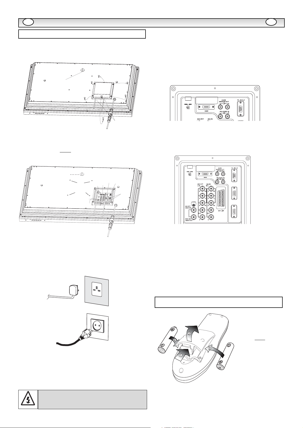
■ REMOVE TERMINAL COVER AS INDICATED BELOW.
■ CONNECT THE DISPLAY UNIT TO AERIAL, VGA. BNC.AND
SCART CONNECTOR AS BELOW.
■ TERMINAL COVER MUST BE REPLACED WITH CABLE EXITS AS
INDICATED IN THE SKETCH ABOVE.
■
Connect the LCD monitor to Aerial, VGA, and Scart connector as
required.
1. Connect the waterproof in-line power connector to the connector
attached to the LCD monitor as shown above.
2. Connect the correct power cord of the LCD monitor to a wall outlet.
✐ As this product does not have a mains On/Off switch, please
ensure your mains plug is easily accessible.
✐ The LCD monitor is prepared for a mains voltage AC220~240V,
50Hz. To completely switch off the mains, or when the LCD monitor is not to be used for an extended period of time, it is advisable
to disconnect the power cord from the power outlet or disconnect
the mains coupler..
3. Warning: To prevent injury, the unit must be securely attached to
the wall in accordance with the installation instructions.
1.■ HDMI (High Definition Multimedia Interface)
This monitor has an HDMI connector. When connected to the HDMI
source and HDMI is selected using the remote control,There is a short
time period before the picture appears at a much higher resolution.
This connection is located at the back of the monitor next to the aerial
socket.
2. Y,Pb,Pr connection (AV2)
This LCD monitor has a choice of Y, Pb, Pr or RGB , H/V connections
You can connect your DVD player to the Y, Pb, Pr terminals instead
of using a scart lead. This can support high definition in analogue
component form. RGB, H/V can be used as a PC input via the BNC
terminal.
3. PC connection
This LCD monitor has a PC connector.You can connect a PC to the
LCD monitor and use it as a monitor display (see page 9).
To switch between TV, AV1, RGB, AV2 RGB H/V or Y, Pb, Pr, AV3,
HDMI or PC mode press the TV/ AV switch on your remote control
repeatedly or press and hold the TV/AV button for a few seconds and
a selection menu will appear on screen. Use the e or d buttons to
select the correct mode.
4. RS232C IN/OUT: Is a input for external commands to control the
monitor (see page 9)
Install two "AA" 1.5 volt batteries so that the "+" and "-" marks on the
batteries match the "+" and "-" marks inside the unit into the remote
control handset.
INST
INST
ALLA
ALLA
TION
TION
Step : 1 Connections (Essential)
AC Mains Outlet
WARNING! High voltages are used in the operation of
this set. Refer service to qualified service personnel.
Step : 2 Remote control battery installation
WARNING!
This remote
control is
not
waterproof
GB
GB
Security fixing point
Cable entry
Security fixing point
Audio monitor
AV2 audio
Coaxial aerial IN
AV2 IN/ Out
BNC
Out
IN
HDMI
Serial ports
IN/ Out
Wall
mount
fixing
positions
Services
AV3 IN/Out
BNC
Serial
Port-IN
Service
Serial
Port-OUT
Waterproof in-line connector
Page 5
5
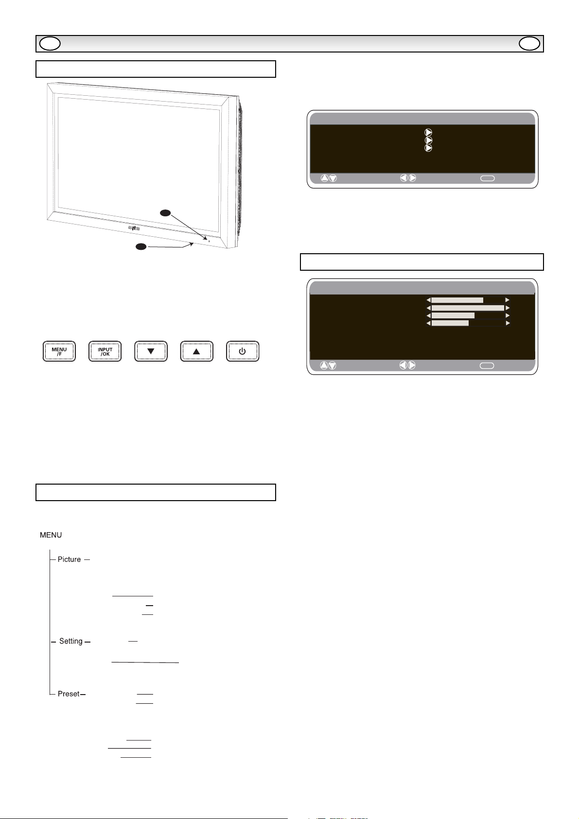
1. The LCD display will have a Standby light to show there is power.
2. Control buttons (bottom edge of cabinet)
Menu/F button: rotate between contrast, Brightness, colour and
sharpness
Input/ OK button: switch between TV , AV1, RGB, AV2, AV3,
HDMI and PC mode.
ed buttons: adjust channels up and down
4 button: To switch from display to standby mode (to switch off
completely disconnect the monitor from the power supply)
Many of your monitors functions are controlled through the menu
function.
During menu operation the bottom of the screen will show which
controls can be used.
Press the u button to enter the main menu.
A sub menu is selected using the e or d button and pressing the
8 button when the required sub menu is highlighted.
When you have set a Sub menu you can press the MENU button to
exit, then the MENU button again to exit the main menu.
1. Press the MENU button. Select Picture using the e or d button.
Press the 8 button to enter.
Set the picture settings for your “personal” preference.
2. Use the e or d button to select eg. Brightness and the 7 or 8
button to adjust levels.
3. Preset : You can select either your “Personal” settings, or
Dynamic, Standard or Eco settings.
4. Noise Reduction: May be used to reduce any local picture ‘noise’
(granular appearance) being experienced by Using 7 or 8 to select
between Mid / High / Auto / Low / OFF.
5. Dynamic skin tone: May be used to enhance skin tone by Using
7 or 8 to select between On / Off.
Tint : is only available if NTSC equipment is connected.
6. Text Brightness: May be adjusted by Using 7 or 8 button to
select between Min / Mid / Max.
To exit press the MENU button.
✐ Your personal settings are automatically saved when you exit the
menu.
INST
INST
ALLA
ALLA
TION
TION
GB GB
Terminals
Picture menu
Menu Operation
1
2
Main Menu
Picture
Setting
Preset
: Select
: Adjust
MENU
: Exit
Picture
Brightness
Contrast
Colour
Sharpness
Preset Personal / Dynamic / Standard / ECO
Noise Reduction Mid / Max / Auto / / OFF
Dyn. skin tone ON / OFF
Text Brightness Min / Mid / Max
: Select
: Adjust
Min
MENU
: Back
Brightness
Contrast
Colour
Sharpness
Preset Personal / Dynamic / Standard / Eco
Noise Reduction Mid / Max / Auto / OFF / Min
Dyn. Skin
Text Brightness Max / Mid / Min
Child lock OFF / ON
OSD language
Timer
Text Language East / West / Cyrillic / Greek
AV2 setting RGB, H/V / Y Pb Pr
Program Sort (Program sort) Program pos.
Program name
Sound System
Auto Tunning
Frequency
Skip
Memory
Tone ON / OFF
Off Time ON / OFF
MOVE / DELETE
MHz
ON / OFF
OK to save
Page 6

6
REMOTE CONTROL
REMOTE CONTROL
GB
GB
TV/AV switch
To switch from TV, AV1, RGB, AV2, AV3, PC or HDMI mode
press repeatedly. Press and hold in a few seconds, an AV selection
bar appaers. Select the mode you require using the
Screen mode selector
To select the screen mode, Auto, Natural, Full
Zoom 16:9, Title 16:9,Zoom 14:9,title 14:9 or Normal.
Refer to page 11
Direct programme selector
For direct access to programmes
using (0-9) numeric buttons in analogue
and digital. For selection of programme position
10 - 99, for example 23, first press -/-- button
and press 2 and 3 numeric buttons.
MENU
To enter and exit sub menus. Also see page
Cursors up/down
To adjust the menu levels .
keys
Standby
To switch the TV on and off. Also see page
Programme information call
To display the programme information.
You can also select colour systems in AV mode as follows
AUTO -> PAL -> SECAM -> NTSC3.58
CS button
Press button to scan through all available channels
and back to the original channel.
Programme swap
To switch between current and previous
programme position watched.
Programme up and down
To select the next programme number or
previous programme number.
Picture mode selection
Press the button repeatedly to select the following
picture modes.
Personal - Personal preference mode.
Dynamic - Suitable for brightly lit rooms.
Standard - Normal viewing mode.
Eco - Suitable for dimlt lit rooms and gives a
cinema - like effect.
F/OK
To save the setting in the menu.
JXPLA
Time display
In the TV mode, if the teletext is available
the teletext clock will be displayed on the
screen. Press again to cancel.
Teletext/TV selector
To access this feature press the TXT/TV button the
picture changes from TV - TXT - MIX and back to TV.
Page 7

7
■ Child lock
You can prevent unwanted operation on the LCD monitor via the
buttons on the bottom edge of the monitor.
1. Press the MENU button. Select Setting using the e or d button.
Press the 8 button to enter.
2. Select Child lock using the e or d button.
3. Set the Child lock to Off or On by pressing the 7 or 8 button.
4. Press the MENU button to exit.
■ AV2 setting
In setting menu, to select AV2 press the d button and set to Y,Pb,Pr
or RGB, H/V depending on your external equipment.
1. Press the MENU button. Select Setting using the e or d button
press the 8 button to enter.
2. Select AV2 setting using the e or d button.
3. Press the 7 or8 button to select which Y,Pb,Pr or RGB, H/V.
4. Press the MENU button to exit, this automatically stores your
changes.
4. Press the MENU button to exit.
■ Text Language
1. Press the MENU button. Select Setting using the e or d button
press the 8 button to enter.
2. Select Text language using the e or d button.
3. Press the 7 or8 button to select West, East, Greek or Cyrillic.
4. Press the MENU button to exit.
■ Off-timer setting
The Off timer will switch the monitor into the standby mode when the
selected time has elapsed.
1. Press the MENU button. Select Setting using the e or d button
press the 8 button to enter.
2. Select OFF Timer using the e or d button.
3. Press the 7 or8 button to change time.
The time changes in 5 minute steps.The maximum time is 120 minutes.
If you have set the off timer, a display appears in the corner of the
screen.
✐ If the TV set is switched off by the standby button
4
on the
remote control or by the standby switch 4on the top of the TV
set the timer settings will be cancelled.
1.Press the MENU button.
2.Select Preset using the e or d button. Press the 8 button to
enter.
✐ The preset menu can be used to tune new channels, to re-order
channels and their programme positions, and to make fine adjustments to the tuning.
MENU OPERA
MENU OPERA
TION
TION
Preset menu
Setting menu
Setting menu
GB
GB
Setting
Child lock OFF / ON
OSD Language English
Timer
Text Language Greek/ East/ West/ Cyrillic
: Select
: Adjust
MENU
: Exit
Preset
Preset
Pro gr am So r t
Pro gr am So r t
Program pos.
Pro g ram p o s. 6
Pro g ram name
Pro g ram name
Sound s
Colour s y stem Au t o
Au to tunning
Sound s y stem S-3
requen c 495.25 MHz
F
Autostore
Skip On / Off
Frequen cy 495.25 MHz
Memory OK? / OK
6
ys tem S-1/ S-2/ S-3/ S-4
y
: Select
: Select
OK? / Busy
: Adjust
: Adjust
MENU
MENU
: Back
: Back
TSEW
HSILGNE
HSIDEWS
HSINNIF
HCNERF
HSIKRUT
NAMREG
R
NAILAT
I
NA
IRAGNUH
HSINAPS
HSINAD
ESEUGUTROP
TSAE
HSILOP
AINAMO
VOLS
NAINOTSE
N
HCEZC
NAITAORC
NAIKA
NAI
NEVOLSNAMREG
KEERG
HSINNIFHSILGNE
HSIDEWS
KEERG
HSINADNAMREG
NAIRAGNUH
HCNERFNAILATI
HSIKRUTNAINEVOLS
NAI
C
TAOR
CILLIRYC
EVOL
SHSILOP
NAMREG
ISSUR
HSITTEL
NAITAORC
NAIN
NA
Timer
OFF TIMER 5 ~ 120
: Select
: Adjust
MENU
: Exit
Page 8

8
MENU OPERA
MENU OPERA
TION
TION
■ Program sort.
Use this channel moving feature to move the channels between two
programme positions. This feature is particularly useful after automatic tuning.
You have to choose a programme that you wish to move from one
position to another.
1. Select programme position eg. 4.
2. Press the Green button.
3. Select Channel position you would like the channel moved to
eg.7
4. Press the Green button again.
5. Press the MENU button two times to exit.
■ Program Name.
With this feature individual channels may be renamed by using the
7 or 8 buttons and e or d buttons.
■ Auto tuning
1. Select Auto sort by using the e or d button. Press the OK but-
ton to start scan.
2. While Scan is in progress, channel frequencies will be captured
and stored automatically, starting from position one.
■ Skip.
Skip is situated directly beneath Frequency on the screen.
When ‘ON’ it removes access to a channel using the e or d button.
The only way that selected channel can be accessed will be by
using the direct channel access keys.
■ Memory.
Memory is situated directly beneath Skip on the screen.
When all the preceding headings under preset have been adjusted
to your satisfaction, using the OK button, change ‘OK?’ to ‘OK’ all
the preset settings will be stored automatically.
Preset Menu
■
Channel Table
The table below shows the receivable channels and channel
allocation for this LCD monitor.
■ Frequency.
The frequency shown will be the frequency being dis
played except when Scanning, then the frequency
shown will change as the scan progresses.
1. To manually Select Frequency by using the 5 or 6 button.
(Refer to the channel table.)
You can either...
a) Enter the frequency using the 0-9 buttons referring to the
channel table.
b) Press and hold the 1 or 2 buttons until the frequency
starts scanning (about 5 seconds), scanning will stop when a
channel is found.
c) Keep pressing to de-tune the frequency.
Repeat above until the correct channel is found.
2. Press the 5 or 6 button to select Memory. Press the OK
button to store the new frequency and all other settings.
GB
GB
Program sort
1 6 11
2 7 12
3 8 13
4 9 14
5 10 15
Move Delete
Preset
Preset
Pro gr am So r t
Pro gr am So r t
Prog r am p o s .
Pro g ram p o s. 6
Pro g ram name
Pro g ram name
Sound s
Colour s y stem Au t o
Au to tunning
Sound s y stem S-3
requen c 495.25 MHz
F
Autostore
Skip On / Off
Frequen cy 495.25 MHz
Memory OK? / OK
Preset
Preset
Pro gr am So r t
Pro gr am So r t
Prog r am p o s .
Pro g ram p o s. 6
Pro g ram name
Pro g ram name
Sound s
Colour s y stem Au t o
Au to tunning
Sound s y stem S-3
requen c 495.25 MHz
F
Autostore
Skip On / Off
Frequen cy 495.25 MHz
Memory OK? / OK
6
ys tem S-1/ S-2/ S-3/ S-4
y
: Select
: Select
6
ys tem S-1/ S-2/ S-3/ S-4
y
: Select
: Select
OK? / Busy
OK? / Busy
: Adjust
: Adjust
: Adjust
: Adjust
MENU
MENU
MENU
MENU
: Back
: Back
: Back
: Back
Italian
channels
CCIR
OIRT
Channels
CCIR
channels
Italian
channels
Displayed
channel no.
C 1 43.25
C 2 A E2 R1 48.25
C 3 A E3 55.25
C 4 B E4 R2 62.25
C 5 D E5 R6 175.25
C 6 E E6 R7 182.25
C 7 F E7 R8 189.25
C 8 E8 R9 196.25
C 9 G E9 205.25
C10 H E10 R10 210.25
C11 H1 E11 R11 217.25
C12 H2 E12 R12 224.25
C21 21 E21 E21 471.25
C22 22 E22 E22 479.25
C23 23 E23 E23 487.25
C24 24 E24 E24 495.25
C25 25 E25 E25 503.25
C26 26 E26 E25 511.25
C27 27 E27 E27 519.25
C28 28 E28 E28 527.25
C29 29 E29 E29 535.25
C30 30 E30 E30 543.25
C31 31 E31 E31 551.25
C32 32 E32 E32 559.25
C33 33 E33 E33 567.25
C34 34 E34 E34 575.25
C25 35 E35 E35 583.25
C36 36 E36 E36 591.25
C37 37 E37 E37 599.25
C38 38 E38 E38 607.25
C39 39 E39 E39 615.25
C40 40 E40 E40 623.25
C41 41 E41 E41 631.25
C42 42 E42 E42 639.25
UHF band
C43 43 E43 E43 647.25
C44 44 E44 E44 655.25
C45 45 E45 E45 663.25
C46 46 E46 E46 671.25
C47 47 E47 E47 679.25
C48 48 E48 E48 687.25
C49 49 E49 E49 695.25
C50 50 E50 E50 703.25
C51 51 E51 E51 711.25
C52 52 E52 E52 719.25
C53 53 E53 E53 727.25
C54 54 E54 E54 735.25
C55 55 E55 E55 743.25
C56 56 E56 E56 751.25
C57 57 E57 E57 759.25
C58 58 E58 E58 767.25
C59 59 E59 E59 775.25
C60 60 E60
C61 61 E61 E61 791.25
C62 62 E62 E62 799.25
C63 63 E63 E63 807.25
C64 64 E64 E64 815.25
C65 65 E65 E65 823.25
C66 66 E66 E66 831.25
C67 67 E67 E67 839.25
C68 68 E68 E68 847.25
C69 69 E69 E69 855.25
E60 783.25
Displayed
Vision
channel no.
Frequency
[MHz]
C75 X X 69.25
C76 Y Y R3 76.25
C77 C/Z Z R4 83.25
C78 Z+1 Z+1 R5 90.25
C79 Z+2 Z+2 97.25
C80 S1 S1 105.25
C81 S2 S2 112.25
C82 S3 S3 119.25
C83 S4 S4 126.25
C84 S5 S5 133.25
C85 S6 S6 140.25
C86 S7 S7 147.25
C87 S8 S8 154.25
C88 S9 S9 161.25
C89 S1S S10 168.25
C90 S11 S11 231.25
C91 S12 S12 238.25
C92 S13 S13 245.25
C93 S14 S14 252.25
C94 S15 S15 259.25
C95 S16 S16 266.25
C96 S17 S17 273.25
C97 S18 S18 280.25
C98 S19 S19 287.25
C99 S20 S20 294.25
H21 S21 S21 303.25
H22 S22 S22 311.25
H23 S23 S23 319.25
H24 S24 S24 327.25
H25 S25 S25 335.25
H26 S26 S26 343.25
H27 S27 S27 351.25
H28 S28 S28 359.25
H29 S29 S29 367.25
H30 S30 S30 375.25
H31 S31 S31 383.25
H32 S32 S32 391.25
H33 S33 S33 399.25
H34 S34 S34 407.25
H35 S35 S35 415.25
H36 S36 S36 423.25
H37 S37 S37 431.25
H38 S38 S38 439.25
H39 S39 S39 447.25
H40 S40 S40 455.25
H41 S41 S41 463.25
channels
OIRT
Channels
Vision
Frequency
[MHz]
Page 9

9
Connect your PC to the connector on the left side terminal of the
set. Once connected select PC mode via the v button on your
remote control. The set will become a monitor for the PC.
By pressing the MENU button on the remote control a menu window
will appear on screen, this allows the settings to be adjusted.
To adjust the Picture settings select picture using the e or d buttons
on the remote then the 8 button to enter the following picture
settings menu.
Press the 7 or 8 buttons to adjust the Picture brightness and the
same to adjust the contrast of the picture.
Picture position changes the picture horizontally or vertically, this is
done by using the 7 or 8 buttons on the remote control.
Video adjust changes the Phase and the clock of the screen. If the
picture is blurred or grainy this function will adjust it to a clearer
picture.
Auto Adjust will automatically adjust the picture by using the 8
button. This will change all the above settings automatically .Auto
adjust can also be achieved by pressing the
button on the remote control
Resolution displays the current resolution of the picture. This is just
for information and cannot be adjusted.
Using the 7 or 8 buttons it is possible to adjust the tone of the
screen using the White tone Red(R) / Green (G)/ Blue(B). This will
adjust the picture to show more of the chosen colour for example if
red is selected you can adjust the red in the picture to increase or
decrease using the 7 or 8 buttons
Native Resolution is used when the PC can output WXGA
1366 x 768pixels. The setting on your Monitor can be changed
to receive XGA or WXGA signal using the 7 or 8 buttons . Once the
signal has been selected, save the settings by switching off then on
the monitor using the power button.
To select the Settings menu press the menu button on your remote
and using the e or d buttons to select Settings. The 8 button will
enter the settings menu.
Child lock/ Timer and AV2 settings are the same as in the TV mode
(pg 7)
Power save if turned ON will turn the LCD monitor into Powersave
mode after 1 minute if no signal is detected, the LED light will turn
blue to indicate stand by. The TV will automatically turn on when a
signal has been detected. Use 7 or 8 buttons to select ON or OFF.
The TV control commands are used to control a TV through RS232C from a computer.
Serial Interface Specification
Transfer Specification
1. Transmission Speed: initial setting value is 19200
2. Transmission speed can be changed by service mode.
Connection
The Designated RS-232C serial cable that is provided with the LCD
monitor must be used for a connection to a computer and LCD
monitor
Notes for communication
The TV command is defined by one command/ one line that starts
with “C” and ends with carriage return (0x0D)
There are two types of commands:
Functional Execution Command e.g Co5[CR] (table on page 75)
Status Read Commands e.g “CR0 [CR] (see table on page 75)
Setting the monitor address in RS232 mode
To Access hotel mode press the green button on the remote control
and hold for 5 seconds. Anew screen will appear.
Each monitor can have a specific Address for example 007, which
helps command that monitor individually and will not effect other
monitors connected to a controlling PC
Address format command
The addressing format command is used for operating multiple
monitor sets from a single PC via the RS232C command line. If you
set your monitor address to ‘000’, it will never respond to any
addressing command from the PC.
If the address from the PC is ‘FFF’, all monitor sets will execute the
command.
The Address format command is defined by one command, one line
which starts with ‘A’and ends with carriage return.(0 x0D)
The Monitor starts to decode when it receives a carriage return
(0x0D)
An address is added at the top of a control command (same as a
address command)
Example:
Functional execution command:
“A001C05” [CR] means address is 001 and the control command is
C05
Status read command
“A001CR0”[CR] means address is 001 and command is CR0
The monitor can set its own address in the hotel option menu
(above) The address range is 000 - 999, the default address will be
000
The baud rate indicates the unit for transfer speed of data
from the PC to the monitor sets
PC menu settings
PC OPERATION
GB GB
RS232C settings
Main Menu
Picture
Setting
MENU
MENU
MENU
: Exit
: Back
: Back
: Select
: Adjust
Picture
Brightness
Contrast
Position
Video Adjust
Auto Adjust
Resolution
White Tone R
White Tone G
White Tone B
Native Resolution
: Select
1024 X 768 @60Hz
XGA / WXGA 1366 x 768
: Adjust
Setting
CHILD LOCK OFF / ON
Timer
AV2
Power save OFF/ON
: Select
RGB, HV/ Y,Pb,Pr
: Adjust
ITEM
Synchronous system
Transmission Speed
Data Length
Parity
Stop Bit
Flow Control None
PC
COM 1
CD
1
2
RXD
3
TXD
DTR
4
SG
5
DSR
6
RTS
7
8
CTS
RING
9
(D-Sub 9 Pin) (D-Sub 9 Pin)
Hotel
Hotel mode ON / OFF
On program OFF/ 1~99
Preset ON / OFF
Address 007
Baud Rate 19200
: Select
SPECIFICATION
Asynchronous
9600 / 19200
8 bit
None
1
TV CONTROL
PORT
N.C.
1
2
RXD
TXD
3
N.C
4
SG
5
N.C
6
RTS
7
CTS
8
9
N.C.
/ AV1-AV3 /RGB/ HDMI/ PC
: Adjust
MENU
: Exit
Page 10

10
TELETEXT / OTHER FEA
TELETEXT / OTHER FEA
TURES
TURES
Teletext reception
If your aerial signal is poor, the teletext reception operation may be
erratic.
Teletext brightness level
You can change the teletext brightness level. Please return to TV
mode.(See Picture menu -Text Brightness on page 7).
■ Switching into /from standby mode
The Standby mode is used for switching the LCD monitor off for
short periods of time. In standby mode the monitor is switched off
but is still receiving mains power.
● To turn the monitor into standby mode, press the
4
button.
The blue power indicator illuminates more brightly.
● To turn the monitor ON from standby mode, press any of the
following buttons:
4,5,6
or
0-9 buttons.
■ Auto shut off
This monitor will automatically switch into the standby mode, 10
minutes after a signal is no longer received. The time until the set
will switch off is displayed on the screen.
■ Sound system selection and Programme
information
Press the button to display the programme information such as
current programme number, station name, stereo status, sound system and remains time if set the timer, for about 5 seconds.
S-1: B/G sound system
S-2: D/K sound system
S-3: I Sound system
S-4: France SECAM L/L’system
■ Use of Audio Output Jacks
The audio monitor out sockets on the rear of the set provide a fixed
level audio output for reproducing sound via your audio equipment.
Teletext
Other functions
GB GB
If you find the power indicator flashing, disconnect
power cord from the power outlet and contact our
Service desk.
This warning is a sign to let you know that the power
protection function of this TV set is now operating.
Direct access to page.
All the numeric buttons can be used
to select a page number directly.
If you need page 301, then press 3 then
0 and then 1.
Sub page access.
Some text pages are made up of severall
sub pages which rotate automatically. If you
wish to view page 4 of 8 then press the sub
page button.
"----" will appear. Enter 0004 and the page
will appear.
Index page selector
This selects one of the teletext index pages.
Cursor
Press the button to select the next page
or the previous page number
Direct Access to subjct headings.
Coloured boxes are displayed at
bottom of screen, the four coloured buttons
give access to the corresponding subject
or pages.
JXPLA
Standby
To switch the TV on and off.
Reveal switch.
This reveals hidden items on the teletext
page eg:a hidden answer to a quiz question.
Page up and down
To select the next or
previous page numbers
Size switch
This will make either the top half
or the bottom half of the page expand
to fill the screen.
Teletext / TV
to access this featurepress the TXT/TV button
the picture changes from TV-TXT-MIX and
back to TV.
.
Page 11

11
■ Screen options
Today there are various transmission formats with different size
ratios, eg. 4:3 , 14:9, 16:9 and video formats such as letterbox.
■ Auto
It automatically switches to the optimum screen mode according to
the WSS signal provided in the receiving signal source. If the signal
does not have it, the monitor keeps current screen mode.
✐ This setting may cause the picture to change when a different
format is received eg. when an advert is received.
✐ WSS (Wide screen signalling)
Some broadcasters transmit this signal and some VCR tapes have it
included . The signal identifies the picture format ratio (16:9, 14:9,
4:3 etc.).
If WSS is not being received and you are not happy with your picture
this monitor provides you the option to change it with the following
options.
Press the WIDE button repeatedly to select your desired setting.
✐ When in High Resolution (720p / 1080i) YPbPr or HDMI, the pic-
ture will remain fixed in 16:9 format ‘Full size’ and may not be
changed.
OPERA
OPERA
TION
TION
GB
GB
TITLES ON SCREEN
TITLES ON SCREEN
TITLES ON SCREEN
TITLES ON SCREEN
Selecting of picture size
■ Title - In 14:9
■ Zoom 14:9
■ Natural
■ Normal
■ Full
■ Zoom 16:9
■ Title - In 16:9
4:3 14:9 16:9
Letterbox Video
4:3 14:9 16:9
The correct picture
width is maintained
but the top and
bottom are
cropped.
Zooms in slightly
cropping the top
and bottom.
4:3 14:9 16:9
As Zoom (16:9),
but bottom is
compressed even
more to allow
subtitles to be
seen.
As Zoom (16:9),
but bottom is
compressed even
more to allow
subtitles to be
seen.
Zooms in slightly
cropping the top
and bottom.
TITLES ON SCREEN
As Zoom (16:9),
but bottom is
compressed even
more to allow
subtitles to be
seen.
Letterbox Video
The black bars top
and bottom are
smaller and the
picture height is
compressed slightly.
Letterbox Video
TITLES ON SCREEN
As Zoom (16:9),
but bottom is
compressed even
more to allow
subtitles to be
seen.
Stretches the
picture horizontally
to fill the screen.
The picture is more
stretched at the
edges.
The height is
expanded to fill the
whole screen.
4:3 14:9 16:9
The correct picture
width is maintained
but the top and
bottom are
cropped.
Zooms in slightly
cropping the top
and bottom.
4:3 14:9 16:9
As zoom (14:9), but
bottom is
compressed even
more to allow
subtitles to be
seen.
As zoom (14:9), but
bottom is
compressed even
more to allow
subtitles to be
seen.
The picture fills the
screen and is
proportionally
correct.
Zooms in slightly
cropping the top
and bottom.
TITLES ON SCREEN
As zoom (14:9), but
bottom is
compressed even
more to allow
subtitles to be
seen.
The black bars top
and bottom remain
and the height is
compressed to fit
the picture area.
Letterbox Video
The black bars top
and bottom are
smaller and the
picture height is
compressed slightly.
Letterbox Video
TITLES ON SCREEN
As zoom (14:9), but
bottom is
compressed even
more to allow
subtitles to be
seen.
4:3 14:9 16:9
The whole screen
is filled stretching
the width.
The whole screen
is filled stretching
the height slightly
at the edges.
4:3 14:9 16:9
The correct ratio is
maintained with
black bars on the
left and right.
Black bars left and
right, picture height
is stretched.
The whole screen
is filled with the
corrrect picture
ratio.
Black bars left and
right, picture height
is stretched.
Letterbox Video
The black bars top
and bottom are
present and the
height is
compressed.
Letterbox Video
Black bars left,
right, top and
bottom.
Page 12

12
Common specification
Power source 220~240V 50Hz
Television system System I B/G, D/K, L’L
Colour system PAL(PAL/NTSC3.58 in AV mode),SECAM
Channel coverage UHF: 21-69,
VHF: E2-E12,F2-F10,R1-R12
CATV : X, Y, S1 -S41, B-Q
Aerial input impedance 75 ohm
AV terminal
AV1: CENELECStandard
Input: Composite video, RGB and audio-L/R
Output: TV-output with composite video and audio-L/R
AV2: BNC
Input: RGB, H and V / Y, Pb, Pr audio-L/R
Output: RGB, H and V / Y, Pb, Pr
AV3: BNC
Input: Composite video
Output: Composite video
Audio M.Out: CINCH L/R
HDMI Input : HDMI GROUP Standard
PC Input
Serial port RS232C: Input/ output
CE32LM4WPR-E
Contrast Ratio 1000:1
Screen(inches/ cm) 32” / 81 cm
(viewing measured
diagonally)
Display Resolution 1366 X 768 (WXGA)
Viewing angles H:176°, V:176°
Dimensions (WxHxDmm) 803X493X162
Weight (kg) 21.8
■ NO PICTURE
● Check if monitor is plugged in.
● Try a different channel, if OK, probably station trouble.
■ POOR PICTURE
● Adjust BRIGHTNESS control.
● Adjust FINE TUNING control.
● Check aerial connections.
■ NO COLOUR, PICTURE OK
● Adjust COLOUR control.
● Adjust FINE TUNING control.
● Is the programme in colour ?
■ WEAK PICTURE
● Check aerial connections on back of set.
● Check aerial for broken wires.
● Re-orient aerial.
The following faults are not caused by the receiver:
"GHOSTS"
Reflections of signals from mountains or high buildings will cause
multiple images, called "Ghosts". These abnormal conditions can be
reduced to minimum by repositioning aerial or by installing new one
suited for your area.
"INTERFERENCE"
Interference may be caused by electrical appliances, car ignition
systems, etc. This should normally be a temporary condition, but
should this interference persist, contact your dealer.
This LCD monitor set allows you to set up the following:-
■ Prohibition of presetting.
This prohibits the use of tuning.
■ Programme position at Start up
SETTING PROCEDURE
1. Press and hold the green button on the remote control
handset for 5 seconds.
2.
Use the 5 or 6 button to highlight Hotel Mode, use the 1
to switch ON or OFF.
3. Select ON program using the
6 button, select the start up
position using the
1 or 2 buttons.
(AV2 - AV1 - 0 - 1 - 2 - 3 - 4 ........99)
4. Press the MENU button to exit from the menu.
SPECIFICA
SPECIFICA
TIONS / HELPFUL
TIONS / HELPFUL
HINTS / HOTEL
HINTS / HOTEL
MODE
MODE
GB
GB
Specification
Helpful hints
Specification
Hotel
Hotel mode ON / OFF
On program OFF/ 1~99
Preset ON / OFF
Address 007
Baud Rate 19200
: Select
/ AV1-AV3 /RGB/ HDMI/ PC
: Adjust
MENU
: Exit
Page 13

13
HDMI / COMPONENT SIGNAL SUPPORT TIMING LIST
GB GB
HD MI signa l supp ort t iming
HD MI signa l supp ort t iming
Vertical
Aspect
Format Timing
Description
Description
60Hz Formats
60Hz Formats
VGA 640x480p 4:3 59.94/60 861 Default format
VGA 640x480p 4:3 59.94/60 861 Default format
480p 720 x480p 4:3
480p 720 x480p 4:3
480p 720 x480p 16:9 59.94/60 861 EDTV
480p 720 x480p 16:9 59.94/60 861 EDTV
720p 1280x720p 16:9
720p 1280x720p 16:9
1080i 1920x1080i 16:9
1080i 1920x1080i 16:9
480i 720(1440)x480i 4:3
480i 720(1440)x480i 4:3
480i 720(1440)x480i 16:9
480i 720(1440)x480i 16:9
50Hz Formats
50Hz Formats
576p 720x576p 4:3
576p 720x576p 4:3
576p 720x576p 16:9
576p 720x576p 16:9
720p 1280x720p 16:9 50 861A HDTV
720p 1280x720p 16:9 50 861A HDTV
1080i 1920x1080i 16:9
1080i 1920x1080i 16:9
576i 720(1440)x576i 4:3
576i
576i 720(1440)x576i 16:9
576i
Format Timing
720(1440)x576i 4:3 50
720(1440)x576i 16:9 50
Aspect
ratio
ratio
Vertical
Freq (Hz)
Freq (Hz)
59.94/60 861 EDTV
59.94/60 861 EDTV
59.94/60 861 HDTV
59.94/60 861 HDTV
59.94/60 861 HDTV
59.94/60 861 HDTV
59.94/60
59.94/60
59.94/60
59.94/60
Where
Where
defined
defined
optional
optional
optional
optional
50 861A EDTV
50 861A EDTV
50 861A EDTV
50 861A EDTV
50 861A HDTV
50 861A HDTV
861A
50
50
861A
optional
optional
861A
861A
optional
optional
861
861
861
861
Remark
Remark
Double clock for
Double clock for
720x480i
720x480i
Double clock for
Double clock for
720x480i
720x480i
Double clock for
Double clock for
720x576i
720x576i
Double clock for
Double clock for
720x576i
720x576i
Horizontal
Resolution
720_400 3 1.47 7 0.09 DOS(VGA)
640_480 31.50 60.00 DOS(VGA VESA 60Hz)
640_480 37.50 75.00 VGA VESA 75Hz
640_480 37.86 72.81 VGA VESA 70Hz
640_480 3 7.86 7 4.38 VGA
640_480 3 5.00 6 7.00 Mac.
640_480 3 4.97 6 6.60 Mac LC 13"
800_600 3 5.16 5 6.25 SVGA VESA 56Hz
800_600 3 7.90 6 0.32 SVGA VESA 60Hz
800_600 4 6.90 7 5.00 SVGA VESA 75Hz
800_600 3 2.70 5 1.09 SVGA
800_600 3 4.50 5 5.38 SVGA
800_600 3 7.90 6 1.03 SVGA
800_600 3 8.00 6 0.51 SVGA
800_600 3 8.60 6 0.31 SVGA
832_624 4 9.00 7 4.00 Mac.
1024_768 48.40 60.00 XGA VESA 60Hz
1024_768 56.50 70.00 XGA VESA 70Hz
1024_768 60.000 75.00 XGA VESA 75Hz
1024_768 44.00 54.58 XGA
1024_768 46.90 58.20 XGA
1024_768 47.00 58.30 XGA
1024_768 48.50 60.02 XGA
1024_768 58.03 72.00 XGA
1024_768 60.31 74.92 XGA
1024_768 61.00 75.70 XGA
1024_768 60.24 75.08 MAC_ Normal 19"
1280_960 60.00 60.00 SXGA VESA 60Hz
1280_1024 79.976 7 5.025 SXGA VESA 7 5Hz
1280_1024 62.50 58.60 SXGA
1280_1024 63.370 60.01 SXGA
1280_1024 63.34 59.98 SXGA
1280_1024 63.74 60.01 SXGA
1280_1024 63.79 60.18 SXGA
1280_1024 63.90 60.00 SXGA
1280_1024 71.69 67.19 SXGA
1280_1024 76.97 72.00 SXGA
1280_1024 81.13 76.107 SXGA
1152_864 64.20 70.40 SXGA
1152_900 61.20 65.20 SXGA
1152_900 61.85 66.00 SXGA
1152_900 71.40 75.60 SXGA
1152_870 68.68 75.06 MAC_ Normal 21"
1280_960 75.00 75.08 Mac.
1280_1024 80.00 75.00 Mac_.
1600_1200 75.00 60.00 UXGA VESA 60Hz
Frequency
(kHz)
Vertical
Frequency
(Hz)
Remark
Component signal support timing
Resolution Horizontal
fre qu enc y (KHz )
720x480 15.735 60i 12.27 SDTV 480i
720x576 15.625 50i 13.50 SDTV 576i
720x480 31.25 60p 27 SDTV 480p
720x576 31.25 50p 27 HDTV 576p
1280x720 45.00 60p 74.25 HDTV 720p
1280x720 37.50 50p 74.25 HDTV 720p
1920x1080 33.75 60i 74.25 HDTV 1080i
1920x1080 28.13 50i 74.25 HDTV 1080i
1920x1080 31.25 50i 74.25 HDTV 1152i
Vertical frequency
(Hz)
Dot Clock
Frequency(Mhz)
Remark
Page 14

74
HDMI / COMPONENT SIGNAL SUPPORT TIMING LIST
HD MI signa l supp ort t iming
HD MI signa l supp ort t iming
Vertical
Aspect
Format Timing
Description
Description
60Hz Formats
60Hz Formats
VGA 640x480p 4:3 59.94/60 861 Default format
VGA 640x480p 4:3 59.94/60 861 Default format
480p 720 x480p 4:3 59.94/60 861 EDTV
480p 720 x480p 4:3 59.94/60 861 EDTV
480p 720 x480p 16:9
480p 720 x480p 16:9
720p 1280x720p 16:9
720p 1280x720p 16:9
1080i 1920x1080i 16:9
1080i 1920x1080i 16:9
480i 720(1440)x480i 4:3
480i 720(1440)x480i 4:3
480i 720(1440)x480i 16:9
480i 720(1440)x480i 16:9
50Hz Formats
50Hz Formats
576p 720x576p 4:3
576p 720x576p 4:3
576p 720x576p 16:9
576p 720x576p 16:9
720p 1280x720p 16:9 50 861A HDTV
720p 1280x720p 16:9 50 861A HDTV
1080i 1920x1080i 16:9
1080i 1920x1080i 16:9
576i 720(1440)x576i 4:3
576i
576i 720(1440)x576i 16:9
576i
PC signal support timing
Format Timing
720(1440)x576i 4:3 50
720(1440)x576i 16:9 50
Aspect
ratio
ratio
Vertical
Freq (Hz)
Freq (Hz)
59.94/60 861 EDTV
59.94/60 861 EDTV
59.94/60 861 HDTV
59.94/60 861 HDTV
59.94/60 861 HDTV
59.94/60 861 HDTV
59.94/60
59.94/60
59.94/60
59.94/60
50 861A EDTV
50 861A EDTV
50 861A EDTV
50 861A EDTV
50 861A HDTV
50 861A HDTV
50
50
Where
Where
defined
defined
861
861
optional
optional
861
861
optional
optional
861A
861A
optional
optional
861A
861A
optional
optional
Remark
Remark
Double clock for
Double clock for
720x480i
720x480i
Double clock for
Double clock for
720x480i
720x480i
Double clock for
Double clock for
720x576i
720x576i
Double clock for
Double clock for
720x576i
720x576i
Component signal support timing
Resolution Horizontal
fre qu enc y (KHz )
720x480 15.735 60i 12.27 SDTV 480i
720x576 15.625 50i 13.50 SDTV 576i
720x480 31.25 60p 27 SDTV 480p
720x576 31.25 50p 27 HDTV 576p
1280x720 45.00 60p 74.25 HDTV 720p
1280x720 37.50 50p 74.25 HDTV 720p
1920x1080 33.75 60i 74.25 HDTV 1080i
1920x1080 28.13 50i 74.25 HDTV 1080i
1920x1080 31.25 50i 74.25 HDTV 1152i
Vertical frequency
(Hz)
Dot Clock
Frequency(Mhz)
Remark
Page 15

76
Part No. 1KA6P1P0305-A N4HLW
Printed in U.K.
 Loading...