

Page 1
CE32LM3WP-B
Please read this Instruction book before using your display unit.
Display Unit
INSTRUCTION MANUAL
Page 2
Do not allow anything to rest on the power
cord.
Do not locate this display unit where the cord
will be damaged by people walking on it.
Do not overload wall outlets and extension
cords as this can result in fire or electric
shock.
Do not place this unit near any heat sources
such as radiators, heaters, stoves and other heat-generating
products (including amplifiers).
It is also advisable whenever possible, not to place this display
unit in direct sunlight as the maximum surface temperature specified for this monitor unit is 60°c.
Do not place this display unit on an unstable stand, shelf or table.
Serious injury to an individual, and damage to the unit may result
if it should fall. Your sales person can recommend an approved
wall mounting kit. A special wall mounting kit is available for this
model.
This display unit should be operated only from the type of power
source indicated on the unit or as indicated in the Operating
Instructions. If you are not sure of the type of power supply, consult your sales person or your local power company.
For added protection it is strongly strongly recommended that
this display unit is supplied via a RCCB. Safety unit.
Never add accessories that have not been specifically designed
for this unit.
This unit is tested to
IP56 (Category 2) standard rating and may
be positioned in an outdoor environment exposed to rain.
This unit is
not protected against temporary or continuous immer-
sion in liquid.
Do not use immediately after moving the display unit from a low
temperature to a high temperature environment, as this causes
condensation, which may result in fire, electric shock, or other
hazards. Before cleaning, unplug the unit from the wall socket.
Do not apply liquid cleaners or aerosol cleaners directly onto the
display unit. Use a damp cloth for cleaning.
Do not mount near an open flame source. Open flames must
never be used near this display unit.
This display unit should not be built in or enclosed in any
way,heat build up will reduce the life of the unit.
Always mount using specifically, the wallmount bracket manufacturers instructions, fixtures and fittings.
This heat sink removes heat from within the unit without the
requirement of an external airflow into the enclosure.
The external surface of the heat sink must not be covered or the
airflow restricted in any way by enclosing the display unit.
The operating temperature range of this unit is 0°c ~ 40°c.
2
INST
INST
ALLA
ALLA
TION/SAFETY
TION/SAFETY
PRECAUTIONS
PRECAUTIONS
CAUTION: Please read and retain for your safety. This display unit has been engineered and manufactured to assure your personal safety,
improper use can result in potential electric shock or fire hazards. In order not to defeat the safeguards incorporated in this display unit,
observe the following basic rules for its installation, use and servicing.
Installation
Use
Important:
THIS PRODUCT MUST BE EARTHED
This equipment is fitted with an approved in-line waterproof mains
coupler and an approved non rewireable UK mains plug. To
change a fuse in this type of plug proceed as follows:
1. Remove the fuse cover and fuse.
2. Fit a new fuse which should be a BS1362 5 Amp A.S.T.A. or
BSI approved type.
3. Ensure that the fuse cover is correctly refitted.
If the fuse cover is lost or damaged the plug must NOT be used
but replaced with a serviceable plug.
If the fitted plug is not suitable for your socket outlets, it should be
cut off and an appropriate plug fitted in its place. If the mains plug
contains a fuse, this should have a rating of 5 Amp, ensure the
fuse cover is correctly fitted. If a plug without a fuse is used, the
fuse at the distribution board should not be greater than 5 Amp.
Note: The severed plug must be destroyed to avoid a possible
shock hazard should it be inserted into a 5 Amp socket elsewhere.
The wires in this mains lead are coloured in accordance with the
following code:
Blue -------> Neutral
Brown ----> Live
Green and Yellow ----> Earth
1. The Blue wire must be connected to the terminal which is
marked with the letter “N” or coloured BLACK.
2. The Brown wire must be connected to the terminal with the
letter “L” or coloured RED.
3. The Green and Yellow wire must be connected to the terminal
which is marked with the letter “E” or coloured GREEN or
GREEN and YELLOW.
Before replacing the plug cover, make certain that the cord grip is
clamped over the sheath of the lead - not simply over the wires.
Do not attempt to bypass the safety purpose of the grounding
type plug.
THIS UNIT IS NOT DISCONNECTED FROM THE MAINS UNLESS
THE MAINS LEAD IS UNPLUGGED.
THE INSTALLER MUST MAKE SURE THE WATERPROOF IN-
LINE COUPLER IS EASILY ACCESSABLE.
Page 3
3
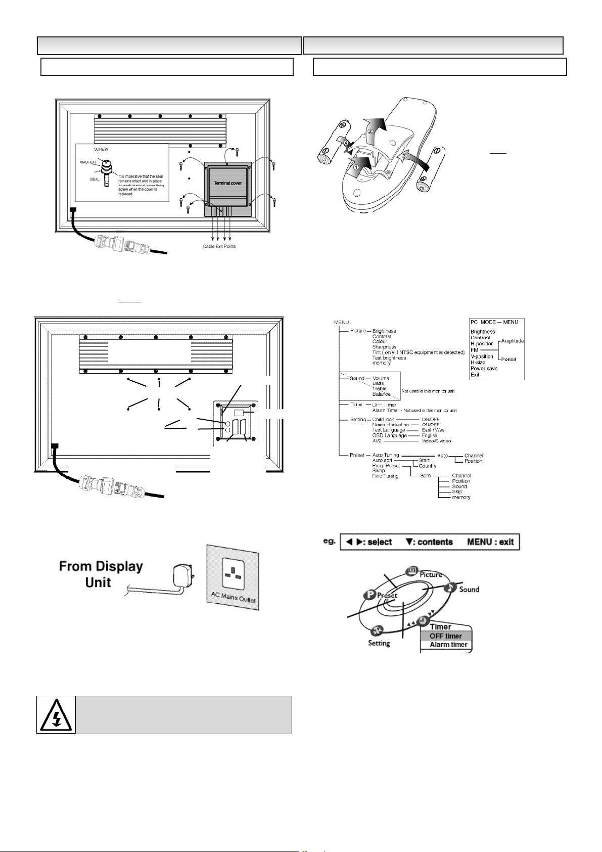
■ REMOVE TERMINAL COVER AS INDICATED BELOW.
■ CONNECT THE DISPLAY UNIT TO AERIAL, VGA. BNC.AND
SCART CONNECTORS AS BELOW.
■ TERMINAL COVER MUST BE REPLACED WITH CABLE EXITS AS
INDICATED IN THE SKETCH ABOVE.
1. Connect the waterproof in-line power connector to the connector
attached to the display unit as above.
2. Connect the power cord of the Display Unit to a wall outlet.
✐ As this product does not have a mains On/Off switch, please
ensure your mains plug is easily accessible.
✐ The display unit is prepared for a mains voltage AC220~240V,
50Hz. To completely switch off the mains, or when the TV set is
not to be used for an extended period of time, it is advisable to
disconnect the power cord from the power outlet or disconnect the
mains coupler.
The Standby mode is used for switching the display unit off for
short periods of time. In standby mode the unit is switched off but is
still receiving mains power.To turn the display unit into standby mode,
press the 4button.When in standby mode press the 4button to
switch on the display.
Install two "AA" 1.5 volt batteries so that the "+" and "-" marks on the
batteries match the "+" and "-" marks inside the unit into the remote
control handset.
Many of your units features are controlled through the remote control
menu function.
During menu operation a bar at the bottom of the screen shows which
controls can be used.
Press the
u button to enter and exit the 5 sub menus Picture,
Sound, Timer, Setting and Preset.
When a sub menu is selected its options are displayed and its colour
will change to yellow.
When you have set each Sub menu you can either press the MENU
button to exit and clear the screen or press the 5 button until the
sub menu is re-selected. Using the 2 or 1 button you can
rotate again.
INST
INST
ALLA
ALLA
TION
TION
Step : 1 Connections (Essential)
WARNING! High voltages are used in the operation of
this set. Refer service to qualified service personnel.
Step : 2 Remote control battery installation
MENU OPERA
MENU OPERA
TION
TION
OUT
IN
BNC CONNECTIONS
PC / VGA
Wall mount fixing positions
AV1 AV2
Scart
connections
Waterproof In-line connector
Coaxial aerial in
HEAT SINK
DO NOT REMOVE
WARNING !
This remote
control is
not
waterproof
Page 4
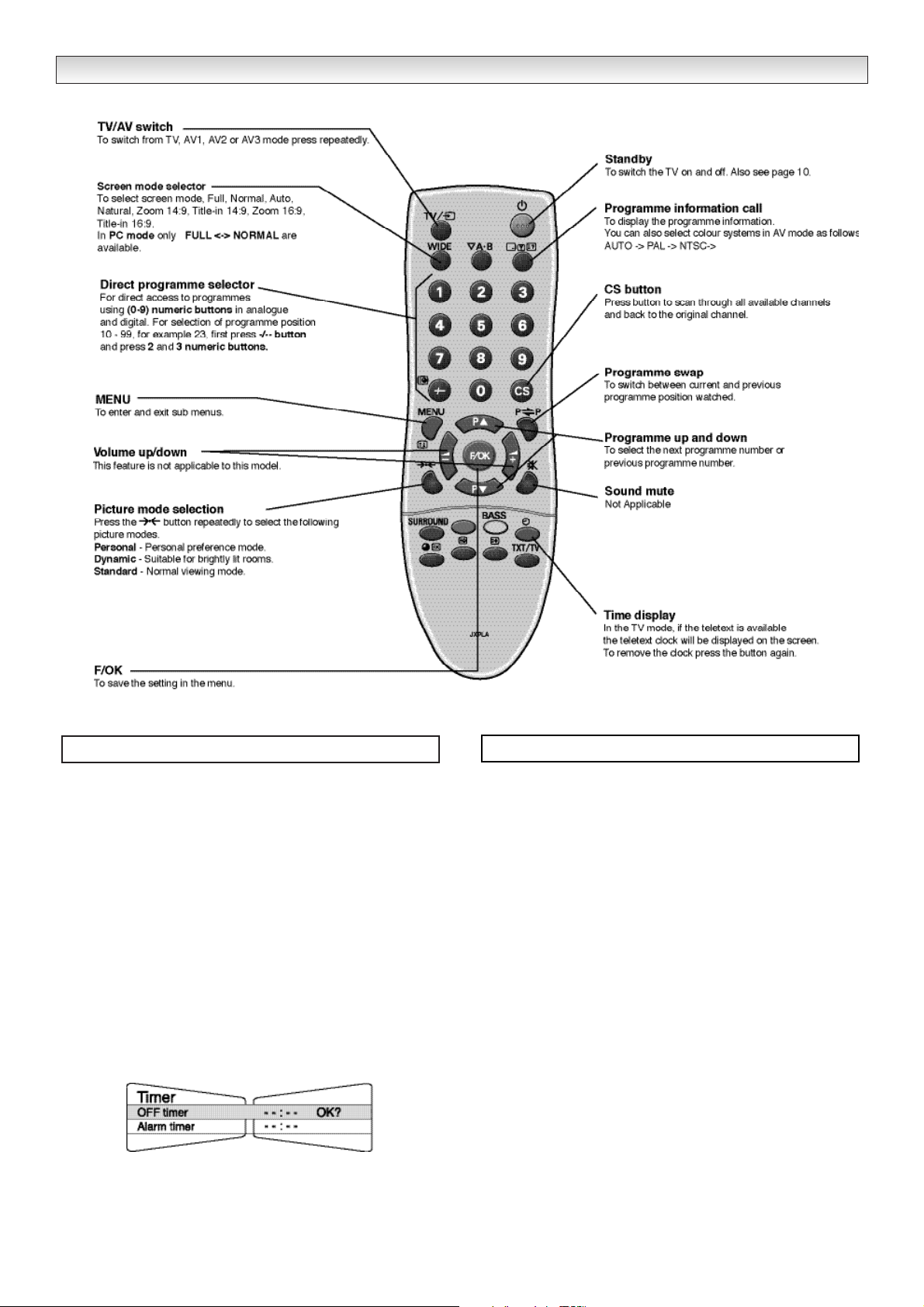
■ Off-timer setting
The Off timer will switch the display monitor into the standby mode
when the selected time has elapsed.
1. Press the
MENU button and select Timer using 2 or 1
button. Select OFF Timer using 5 or 6 button. The com-
plete line turns yellow.
2.
Press the
2 or 1 button to select --:-- (highlighted yellow).
3.
Press the
5 or 6 button to change time.
The time changes in 30 minute steps.The maximum time is 2:00hrs.
4.
Press the
2 or 1 button to highlight complete line (yellow).
5. Press the OKbutton to store your settings.
If you have set the off timer, then one minute before the display
monitor switches off, a display appears on the screen.
✐ If the monitor is switched off by the standby button 4on the
remote control or by the standby switch 4underneath the right
front of the monitor, the timer settings will be cancelled.
Press the MENU button to exit.
■ To Prohibit the use of the Remote Control
1.
Press the RED button and Menu then using the numerical but-
tons enter 7308.
This will toggle on/off the ability to access the monitor unit display
functions via the remote control.
4
REMOTE FUNCTION
Timer menu
Prohibiting the remote control
Page 5

5
Press the MENU button, then the 2 or 1 button to rotate
and select Picture menu. Set the picture settings for your personal
preference.
Use the 5 or 6 to select eg. Brightness, Contrast, Colour and use
the 2 or 1 button to adjust levels.
Tint : is only available if NTSC equipment is connected.
Text brightness : You can set to minimum, centre or maximum.
Use the 5 or 6 button to select and the 2 or 1 button to set.
To memorise these settings press the OK button. (The OK? will
change to OK.)
To exit press the MENU button.
✐ In PC mode Picture menu is not available.
The preset menu can be used to tune new channels, to reorder
channels and their programme positions, and to make fine adjustments to the tuning.
■ Auto Tuning
1. Press the MENU button and select Preset using the 2 or 1
button. Select Auto Tuning using the 5 or 6 button. The complete line turns yellow.
2. Press the 1 button and select Auto.
3. Press the 1 button to start, all available channels are
automatically stored, starting from programme position 01.
After completing this procedure, the display returns to programme
position “01”.
Position changes sequentially as channels are found.
To cancel this tuning operation, press the
MENU button repeatedly.
■ Auto Sort
1. Press the MENU button.
2. Select Preset, press the 5 or 6 button select Auto sort and
press 1.
3. Press the 2 or 1 button to select specific country.
4. Press OK to start automatic sorting and storing of TV stations in your
area. It will sort the channels as in Plug and Play.
To cancel press Menu button repeatedly.
■ Prog. preset.
This is used to preset a received channel in any desired programme
position.
1. Press the MENU button and select Preset, press the 5 or 6
button and select Prog. Preset.
2. Press the 1 button to enter Semi menu.
3. Select Position by pressing the 6 button. Press the -/-- button
and enter the position (01-99) using the 0-9 buttons or 2, 1
button until the position is selected. (eg: to select position 5 press
0 then 5).
4. Press 5 to highlight Channel. Press the -/-- button (C--) to enter
the number directly if known.
You can search for a channel for your selected position. Highlight
Channel, press the 2 or 1 button until a channel is found, if
this is not the one required repeat until it is found (C--/H--).
✐
The selection changes colour to blue, to say that another channel
has been found.
5. Press the 6 button and select Memory, press the OK button to
memorise.(The OK? will change to OK).
Press the MENU button to exit.
Press Button 1 to rotate between Brightness, Contrast, Colour and
Sharpness.
Press
Button 2 to rotate between TV, AV1,RGB, AV2 and PC mode.
Press
Button 3 and 4 to adjust up and down.
Press Button 5 to switch from display to standby mode (to switch off
completely disconnect from the power supply).
MENU OPERA
MENU OPERA
TION / TV/A
TION / TV/A
V MODE
V MODE
Picture menu
Preset menu
Button functions (Bottom edge of cabinet)
Button 1
Button 3
Button 5
Button 2
Button4
Page 6

6
1. Press the TV/AV button on your remote control to rotate between
TV, AV1, RGB, AV2 and PC mode.
When PC mode is selected Press the MENU button the following
screen will appear.
2. Press the 2 or 1 button to rotate between Brightness,
Contrast, H-Position, FM, V- Position, H-size, PS and Exit.
Select which mode you wish to adjust and press the OK button.
Set at your desired level by pressing the 2 or 1 button.
3. Press the OK button again to memorise and return to the main PC
mode screen as shown above.
PS mode.
If you select PS mode it will give you two options to choose. POWER
SAVE and AUTO SHUT OFF.
POWER SAVE. If there is no signal being received, after one minute
the display unit switches into Standby mode. If the signal then
becomes available the display unit will automatically switch itself on,
as long as power is still being received.
AUTO SHUT OFF. If there is no signal being received, after one
minute the display unit switches into Standby mode. If the signal then
becomes available you must press the Standby button to switch the
display unit on again.
1. Press the 2 or 1 button to rotate between POWER SAVE
and AUTO SHUT OFF.
2. Press the OK button when you have chosen, this will save your
selection.
3. Press the OK button to return to the main PC mode screen.
To Exit the menu rotate by pressing the 2 or 1 button until you
select Exit.
4. Press the OK button to exit.
To manually operate the PC mode. Use the following buttons. They
are located on underside of cabinet beneath the blue standby light on
the front of your monitor.
1. Press button 2 to rotate between TV, AV1, RGB, AV2, and PC
mode.
2. Press button 1 (as the OK button) to select the main PC menu
screen.
3. Press button 3 or 4 to navigate through the menu of adjustable
features :- Brightness, Contrast, H-Position, V-Position, H-size, PS
and Exit. Select which feature you wish to adjust and press button 2
(as the OK button) to enter.
4. Using buttons 3 or 4 make the desired adjustment, again press
button 2 (as the OK button) to accept.
5.Using buttons 3 or 4 navigate to EXIT and press button 2 to leave
the feature.
6. If no other feature requires adjustment, using buttons 3 or 4,to
highlight EXIT and press button 2 to leave the PC MENU.
✐ Press button 5 to switch the display unit into standby mode. Press
again to switch on.(to switch off completely disconnect from the
power supply).
✐ In the PC MENU if there is no input signal, the message screen
below will appear.
FM (FUNCTION)
If you have experienced patterning (usually in the form of diagonal
lines across the screen) then select FM. This will give you two
adjustable options. Amplitude (top symbol) and Period (symbol at
right hand side).
Use the level adjustment bars pictured beneath each heading by
pressing the 2 or 1 button to remove the pattern.
When the patterning has been removed then press the OK button
once, then using the 2 or 1 buttons to select exit.
MENU OPERA
MENU OPERA
TION / PC MODE
TION / PC MODE
PC mode
Button 1
Button 3
Button 5
Button 2
Button 4
Button functions
Page 7

7
END-USER LICENCE & SERVICING
END-USER LICENCE & SERVICING
The product (meaning the equipment or appliance to which this
documentation relates) incorporates Software (the software applications, utilities and modules embedded within the Product) which is
owned by Sanyo or its licensors. Before using the product, please
read the End-User Licence Conditions detailed below. If you do not
agree to the terms and conditions of the End-User Licence, Please
do not proceed to use the Product- repack the Product unused and
return it to your supplier together with proof of purchase for a full
refund. By using the product, you agree to be bound by the terms
and conditions of the End-User Licence.
Licence Grant, Conditions and restrictions
1. Sanyo grants you a non-exclusive, world-wide (subject to export
controls), non-transferable (except as permitted by 2 below),
royalty-free licence to use the Software upon and with the Product.
2. You may not transfer any of your licence rights in the Software
without the prior written consent of SANYO and if consent is
provided then the Software shall only be transferred in conjunction
with the transfer of the Product AND provided that the transferee
has read and agreed to accept the terms and conditions of this
licence.
3. You must ensure that the copyright, trademark and other protective
notices contained in the Software are maintained and not altered
or removed.
4. The Software provided hereunder is copyrighted and licenced (not
sold). SANYO especially does not transfer title or and ownership
rights in the Software to you. The Software provided hereunder
may contain or be derived from portions of materials provided to
SANYO under licence by a third party supplier.
5. Except as expressly permitted by statute you may not;
● use the Software in conjunction with any other computer
hardware other than the product;
● copy all or part of the Software;
● incorporate all (or any of) the Software into other programs
developed by (or on behalf of) you and/or used by you;
● reverse-engineer, decompile or disassemble the Software;
● make the Software (or any part of it) available, or permit its
redistribution, for use with any computer hardware other than
the Product; or rent, lease, gift, loan, sell, distribute or transfer
possession of the whole or any part of the Software.
Termination
This licence is effective until terminated. This licence will terminate
automatically without notice if you fail to comply with any of its
provisions.
Disclaimer
1. The Software is(to the extent permitted by law) supplied ‘as is’ and
SANYO and its suppliers expressly exclude all warranties, express
or implied, including (but not limited to) warranties of satisfactory
quality, fitness for purpose and non-infringement (save to the
extent that the same are not capable of exclusion at law).
2. In no circumstances will SANYO be liable for any direct, indirect,
consequential, or incidental damage (including loss of profits,
business interruption, loss of data or the cost of procurement of
substitute goods, technology or services) arising out of the use or
the inability to use the Software (save to the extent that such
liability is not capable of exclusion at law).
General
1. This End-User Licence will be governed by laws of England and
the User may only bring claims in the English Courts and SANYO
shall be entitled to bring a claim in the courts of any jurisdiction.
2. The above terms and conditions supersede any prior agreement,
oral or written, between you and SANYO relating to the Software.
End-User Licence
Your display unit is fully transistorised and does not contain any user serviceable components.
If there is a fault with this unit, you MUST NOT in any way tamper with the rear cover fixings or remove the rear cover:
Please refer to Warranty / Exchange Documentation on the opposite page.
Unplug the display unit from the wall outlet and refer servicing to qualified service personnel under the following conditions:
■ If the power cord or plug is damaged.
■ If the display unit has been dropped or the cabinet has been damaged.
■ If the display unit exhibits a distinct change in performance.
■ If the display unit does not operate normally by following the operating instructions.
Adjust only those controls that are covered in the operating instructions as improper adjustment of other controls may result in damage. This will
often require extensive work by a qualified technician to restore the
display unit
to normal operation.
Servicing
THIS MONITOR UNIT IS SEALED TO IP 56 STANDARD. THE INTEGRITY OF THE
OF THE ENCLOSURE MUST NOT BE TAMPERED WITH OR BREACHED.
Page 8

8
Common specification
Power source 220~240V 50Hz
Television system System B/G, D/K, I, L/L
Colour system PAL / SECAM
(PAL / SECAM / NTSC3.58 in AV mode)
Channel coverage VHF: E2-E12, F2-F10, R1-R12
UHF: 21-69,
CATV:X,Y,Z,S1-S41
Aerial input impedance 75 ohm
AV terminal
AV1: CENELEC Standard(Minus Audio input/output)
Input: Composite video, RGB and 5v RGB
AV2: CENELEC Standard (Minus Audio input/output)
Input: Composite video, RGB, S-VHS
or BNC composite video input.
AV3: PC
Input: VGA (640x 480, 60Hz)
SVGA (800 x 600, 60Hz)
XGA (1024 x 768, 60Hz)
CE32LM3WP-B
Contrast Ratio 1000:1
Screen size 32in / 81cm
(viewing measured diagonally)
Display Resolution 1366 X 768 (WXGA)
Viewing angles H:176°, V:176°
Dimensions (WxHxDmm) 816 x 510 x 165
(including stand)
Weight (kg) 22.8
IP 56 (Category 2)
Operating Temperature 0°c ~ 40°c
This unit must only be used in Landscape orientation.
Please do not connect both scart and
BNC at the same time,They have a
common input.
Specification
SPECIFICATIONS
Page 9

9
“WEATHERPROOF” WARRANTY
Model No. CE32LM3WP-B
Terms & Conditions
Warranty
Sanyo Europe Limited (SEL) warrants to the initial purchaser only that if the product becomes defective due to faulty
materials or manufacture SEL will at its discretion, for a period of 24 months from the date of sale, replace or
repair, free of charge, any defective component part of the equipment, subject to the following conditions:-
Proof of purchase is required at the time of any claim.
The equipment has at all times been used in accordance with the operating instructions issued by the Company and
has not been connected to an electrical mains supply for which it has not been designed.
Accidental damage including mishandling, transport or damage caused by negligence, vandalism or misuse is
excluded from warranty. SEL reserves the right to invoice the cost of repairs or replacement of any returned product
under warranty found to have failed due to misuse.
Unauthorised repair or modification to the equipment including the removal of any part of the product casing screw
devices and seals will render the warranty null and void.
Failure as a result of fair wear and tear is specifically excluded.
If SEL determine that the problem is due to a manufacturing fault, an exchange product will be provided. It will be of
a similar but not necessarily of identical specification to the returned product.
The exchange product will be delivered within 48 hours (excluding Weekends and Bank Holidays) provided SEL are
notified by fax or e-mail by 2.00 p.m.
Product removal and re-installation should be arranged by the end user and is not covered by the terms of this warranty.
This warranty is not transferable and is only applicable within the United Kingdom and the Republic of
Ireland.
This warranty does not affect the statutory rights of the initial purchaser.
Contact Telephone No. for all
Warranty enquiries: 01923 477195
Please have model and serial number details
and proof of purchase at time of calling
SEL Service
Sanyo Europe Limited
Commercial Division
Sanyo House
18 Colonial Way
Watford
Hertfordshire
WD24 4PT
WARRANTY DOCUMENT
Page 10

101112
Page 11

Page 12

Part No. 1KA6P1P0278-A N2MJW
Printed in U.K.
 Loading...