

Page 1
EC 3ML2
3 B
-
.ti
n
u y
al
psi
d
ruoy gnis
u
e
ro
f
eb koob
n
oi
tc
u
rt
s
nI siht
d
a
er e
s
a
elP
t
in
U
y
alps
iD
LAUNA
M
N
OITCURTSN
I
Page 2
Do not allow anything to rest on the power
cord.
Do not locate this display unit where the cord
will be damaged by people walking on it.
Do not overload wall outlets and extension
cords as this can result in fire or electric
shock.
Do not place this unit near any heat sources
such as radiators, heaters, stoves and other heat-generating
products (including amplifiers).
Do not place the this display unit in direct sunlight.
Do not place this display unit on an unstable stand, shelf or table.
Serious injury to an individual, and damage to the unit may result
if it should fall. Your sales person can recommend an approved
wall mounting kit. A special wall mounting kit is available for this
model.
This display unit should be operated only from the type of power
source indicated on the unit or as indicated in the Operating
Instructions. If you are not sure of the type of power supply, consult your sales person or your local power company.
For added protection it is strongly strongly recommended that
this display unit is supplied via a RCCB. Safety unit.
Never add accessories that have not been specifically designed
for this unit.
Never spill liquids of any kind on this display unit.
Do not place items such as vases containing liquid on top of the
unit.Some internal parts carry hazardous voltages and contact
may result in an electric shock hazard.
Do not expose the display unit to rain or use near water.
For example, near a bathtub, in a wet basement, etc.
Do not use immediately after moving the display unit from a low
temperature to a high temperature environment, as this causes
condensation, which may result in fire, electric shock, or other
hazards. Before cleaning, unplug the unit from the wall socket.
Do not apply liquid cleaners or aerosol cleaners directly onto the
display unit. Use a damp cloth for cleaning.
Do not mount near an open flame source. Open flames must
never be used near this display unit.
This display unit should not be built in or enclosed in any
way,heat build up will reduce the life of the unit.
Always mount using recommended and substantial fixtures and
fittings.
This heat sink removes heat from within the unit without the
requirement of an external airflow into the enclosure.
The external surface of the heat sink must not be covered or the
airflow restricted in any way by enclosing the display unit.
2
INST
INST
ALLA
ALLA
TION/SAFETY
TION/SAFETY
PRECAUTIONS
PRECAUTIONS
CAUTION: Please read and retain for your safety. This display unit has been engineered and manufactured to assure your personal safety,
improper use can result in potential electric shock or fire hazards. In order not to defeat the safeguards incorporated in this display unit,
observe the following basic rules for its installation, use and servicing.
Installation
Use
Important:
THIS PRODUCT MUST BE EARTHED
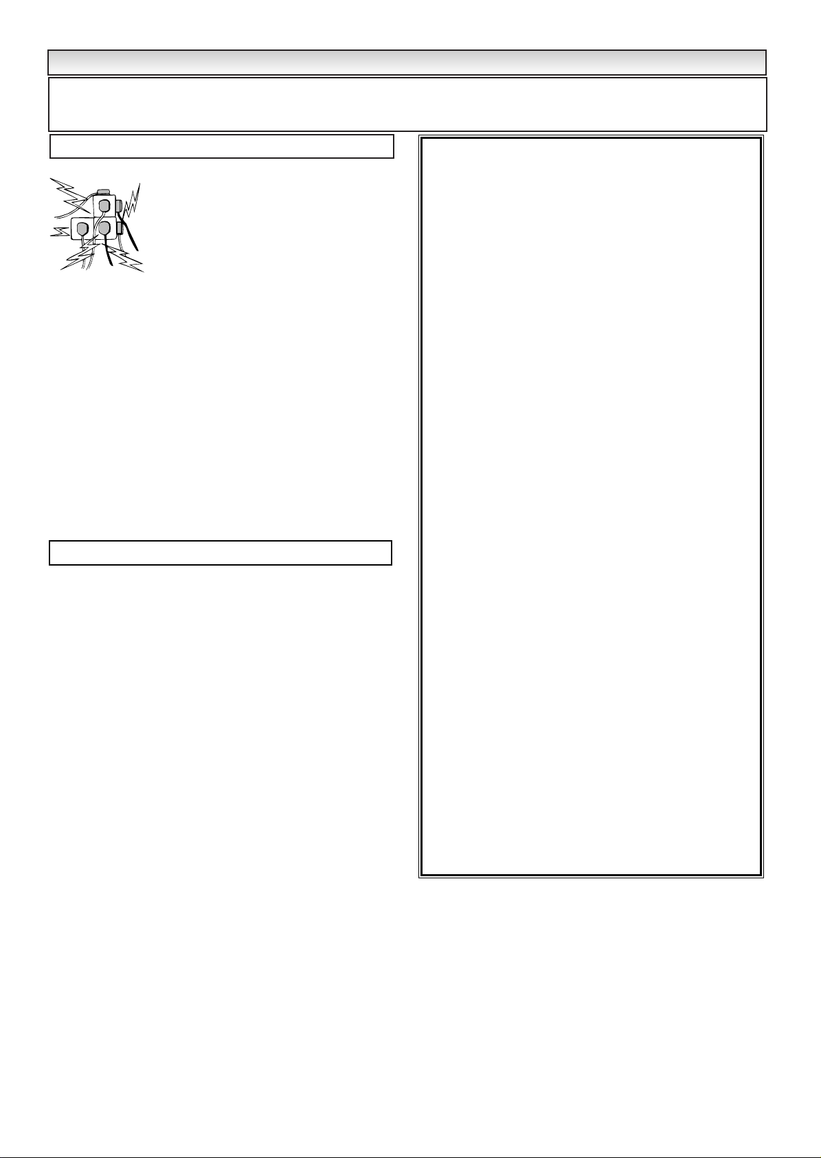
This equipment is fitted with an approved in-line mains coupler
and an approved non rewireable UK mains plug. To change a fuse
in this type of plug proceed as follows:
1. Remove the fuse cover and fuse.
2. Fit a new fuse which should be a BS1362 13Amp A.S.T.A. or
BSI approved type.
3. Ensure that the fuse cover is correctly refitted.
If the fuse cover is lost or damaged the plug must NOT be used
but replaced with a serviceable plug.
If the fitted plug is not suitable for your socket outlets, it should be
cut off and an appropriate plug fitted in its place. If the mains plug
contains a fuse, this should have a rating of 13 Amp, ensure the
fuse cover is correctly fitted. If a plug without a fuse is used, the
fuse at the distribution board should not be greater than 13 Amp.
Note: The severed plug must be destroyed to avoid a possible
shock hazard should it be inserted into a 13Amp socket elsewhere.
The wires in this mains lead are coloured in accordance with the
following code:
Blue -------> Neutral
Brown ----> Live
Green and Yellow ----> Earth
1. The Blue wire must be connected to the terminal which is
marked with the letter “N” or coloured BLACK.
2. The Brown wire must be connected to the terminal with the
letter “L” or coloured RED.
3. The Green and Yellow wire must be connected to the terminal
which is marked with the letter “E” or coloured GREEN or
GREEN and YELLOW.
Before replacing the plug cover, make certain that the cord grip is
clamped over the sheath of the lead - not simply over the wires.
Do not attempt to bypass the safety purpose of the grounding
type plug.
THIS UNIT IS NOT DISCONNECTED FROM THE MAINS UNLESS
THE MAINS LEAD IS UNPLUGGED.
THE INSTALLER MUST MAKE SURE THE IN-LINE COUPLER IS
READILY OPERABLE.
7
END-USER LICENCE & SERVICING
END-USER LICENCE & SERVICING
The product (meaning the equipment or appliance to which this
documentation relates) incorporates Software (the software applica-
tions, utilities and modules embedded within the Product) which is
owned by Sanyo or its licensors. Before using the product, please
read the End-User Licence Conditions detailed below. If you do not
agree to the terms and conditions of the End-User Licence, Please
do not proceed to use the Product- repack the Product unused and
return it to your supplier together with proof of purchase for a full
refund. By using the product, you agree to be bound by the terms
and conditions of the End-User Licence.
Licence Grant, Conditions and restrictions
1. Sanyo grants you a non-exclusive, world-wide (subject to export
controls), non-transferable (except as permitted by 2 below),
royalty-free licence to use the Software upon and with the Product.
2. You may not transfer any of your licence rights in the Software
without the prior written consent of SANYO and if consent is
provided then the Software shall only be transferred in conjunction
with the transfer of the Product AND provided that the transferee
has read and agreed to accept the terms and conditions of this
licence.
3. You must ensure that the copyright, trademark and other protective
notices contained in the Software are maintained and not altered
or removed.
4. The Software provided hereunder is copyrighted and licenced (not
sold). SANYO especially does not transfer title or and ownership
rights in the Software to you. The Software provided hereunder
may contain or be derived from portions of materials provided to
SANYO under licence by a third party supplier.
5. Except as expressly permitted by statute you may not;
● use the Software in conjunction with any other computer
hardware other than the product;
● copy all or part of the Software;
● incorporate all (or any of) the Software into other programs
developed by (or on behalf of) you and/or used by you;
● reverse-engineer, decompile or disassemble the Software;
● make the Software (or any part of it) available, or permit its
redistribution, for use with any computer hardware other than
the Product; or rent, lease, gift, loan, sell, distribute or transfer
possession of the whole or any part of the Software.
Termination
This licence is effective until terminated. This licence will terminate
automatically without notice if you fail to comply with any of its
provisions.
Disclaimer
1. The Software is(to the extent permitted by law) supplied ‘as is’ and
SANYO and its suppliers expressly exclude all warranties, express
or implied, including (but not limited to) warranties of satisfactory
quality, fitness for purpose and non-infringement (save to the
extent that the same are not capable of exclusion at law).
2. In no circumstances will SANYO be liable for any direct, indirect,
consequential, or incidental damage (including loss of profits,
business interruption, loss of data or the cost of procurement of
substitute goods, technology or services) arising out of the use or
the inability to use the Software (save to the extent that such
liability is not capable of exclusion at law).
General
1. This End-User Licence will be governed by laws of England and
the User may only bring claims in the English Courts and SANYO
shall be entitled to bring a claim in the courts of any jurisdiction.
2. The above terms and conditions supersede any prior agreement,
oral or written, between you and SANYO relating to the Software.
End-User Licence
Your display unit is fully transistorised and does not contain any user serviceable components.
You must not remove the rear cover of the display unit by yourself. The apparatus is working with high voltages and could damage
objects or even endanger people. Leave all required repair and service jobs to an authorised service technician. He will exclusively
use such spare parts that are complying with the same safety standards as applicable to the original parts. The use of original spare
parts can prevent fire, shock and other hazards.
Unplug the display unit from the wall outlet and refer servicing to qualified service personnel under the following conditions:
■ If the power cord or plug is damaged.
■ If liquid has been spilt into the display unit receiver.
■ If display unit has been exposed to rain or water.
■ If the display unit has been dropped or the cabinet has been damaged.
■ If the display unit exhibits a distinct change in performance.
■ If the display unit does not operate normally by following the operating instructions.
Adjust only those controls that are covered in the operating instructions as improper adjustment of other controls may result in damage. This will
often require extensive work by a qualified technician to restore the
display unit
to normal operation.
Servicing
Page 3
3
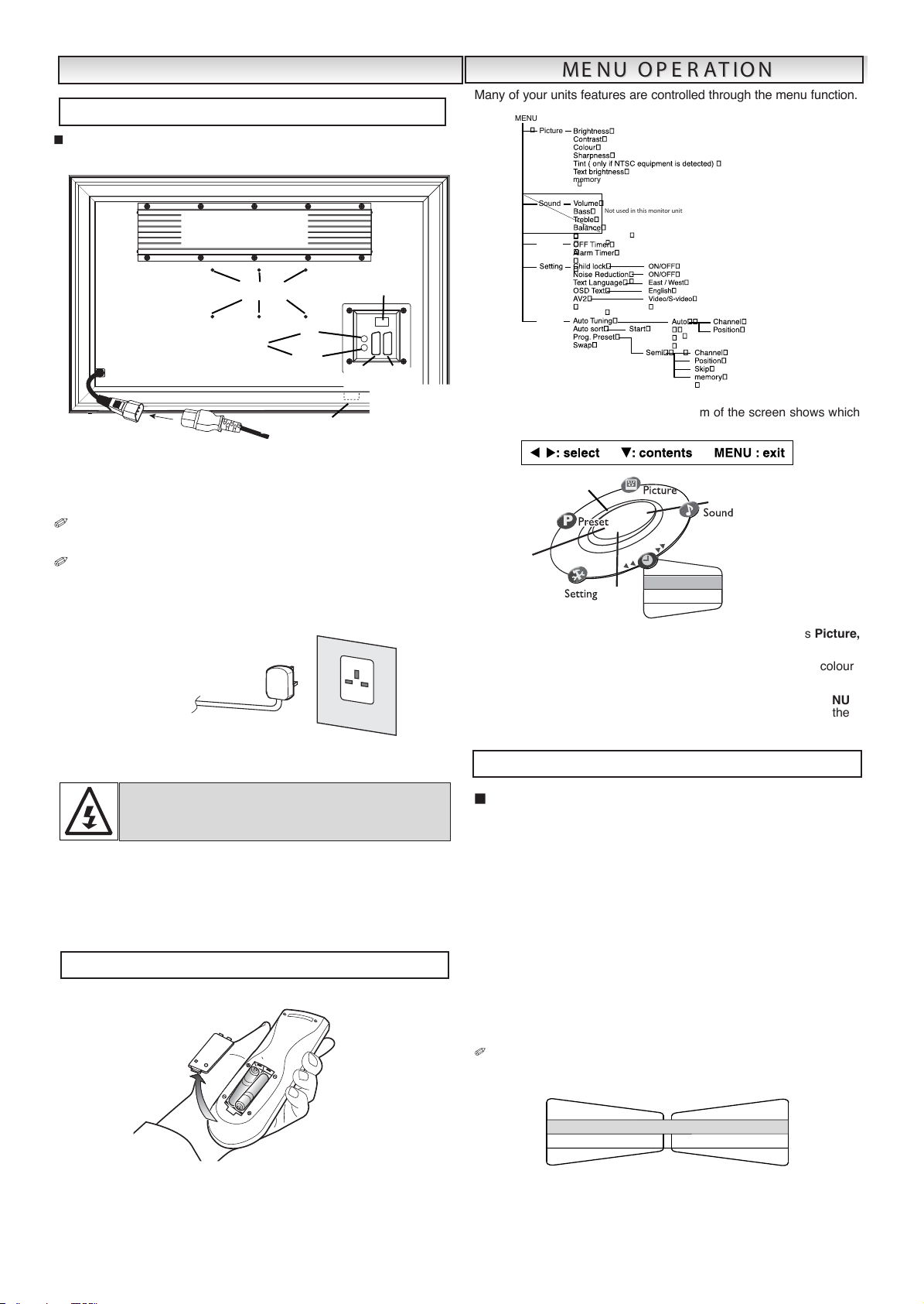
DNA.CNB .AGV ,LAIREA OT TINUYALPSID EHT TCENNOC
.DERIUQER SA SROTCENNOC TRACS
.
1
ot dehcatta rotcennoc eht ot rotcennoc rewop enil-ni eht tcenn
oC
.evo
ba sa tinu yalpsid eh
t
.teltuo llaw a ot tinU yalpsiD eht fo droc rewop eht tcennoC .2
esaelp ,hctiws ffO/nO sniam a evah ton seod tcudorp siht sA
.elbissecca ylisae si gulp sniam ruoy erusne
,V042~022CA egatlov sniam a rof deraperp si tinu yalpsid ehT
si tes VT eht nehw ro ,sniam eht ffo hctiws yletelpmoc oT .zH05
-sid ot elbasivda si ti ,emit fo doirep dednetxe na rof desu eb ot ton
eht tcennocsid ro teltuo rewop eht morf droc rewop eht tcennoc
.relpuoc sniam
:gni
nraW
.3
tinu
eht ,yr
ujni tneverp oT tsum ot dehctatta yleruces
eb
.snoitcurtsni noitallatsni eht h
tiw
ecnadrocca ni
ll
aw eht
rof ffo tinu yalpsid eht gnihctiws rof desu si edom ybdnatS ehT
si tub ffo dehctiws si tinu eht edom ybdnats nI
.em
it fo sdoirep trohs
,edom ybdnats otni tinu y
alp
sid eht nrut oT.rewop sniam gniviecer llits
eht sserp n
ottub .
eht sserp e
dom
ybdnats ni neh
W
nottub .yalpsid eht no hctiws ot
eht no skram "-" dna "+" eht taht os seirettab tlov 5.1 "AA" owt llatsnI
etomer eht otni tinu eht edisni skram "-" dna "+" eht hctam seirettab
.tesdnah lortnoc
.noitcnuf
unem eht hguorht dellortnoc era serutaef stinu ru
oy fo
ynaM
hcihw swohs neercs eht fo mottob eht ta rab a noitarepo unem gniruD
.desu eb nac slortnoc
eht s
serP
ot nott
ub
retne dna
tixe
sunem bus 5 eht
,
erutci
P
gnitteS ,remiT ,dnuoS dna teserP .
r
uoloc sti d
na deyalpsid era snoitpo sti detceles si unem bus a n
eh
W
.wolley ot e
gnahc lliw
e
ht sserp rehtie nac uoy unem buS hcae tes evah uoy nehW UNEM
nottu
b
e
hts
serp
ro n
eercs eht
ra
elc dna tixe o
t
nottub
e
ht litnu
eht gnisU .detceles-er si unem bus
r
o nottub
n
ac uoy
.
niaga etato
r
gnittes remit-ff
O
e
dom
yb
dnats eht otni rotinom yalpsid eht hctiws
lliw
remit ffO ehT
.despale sah emit detc
eles eh
t nehw
.1 eht sserP
nottub UNEM tceles
dna remi
T gnisu ro -tub
not
tceleS.
re
miT FF
O
gnisu ro nottub enil etelpmoc ehT .
.wolley s
nrut
.2
eht sser
P
r
o
nottub .)wolle
y de
thg
ilhgih( --:-- tceles o
t
.3
eht sser
P
r
o nottub .emit egnahc o
t
.srh00:2 si emit mumixam ehT.spets etunim 03 ni segnahc emit ehT
.4
eht sser
P
r
o
nottub
.)wolley( enil ete
lpmoc thg
ilhgih o
t
.5 eht sser
P
K
O
nottub .sgnittes ruoy erots
ot
-inom yalpsid eht erofeb etunim eno neht ,remit ffo eht tes
ev
ah uoy fI
.neercs eht no sraeppa yalpsid a ,ffo sehctiws rot
eht yb ffo dehctiws si rotinom eht fI nottub ybdnats eht no
hct
iws y
bdnat
s eht yb ro lortno
c e
tomer thgir eht htaenrednu
.del
lecnac eb lliw sgni
ttes re
mit
eht ,rot
inom eht fo tnorf
eht sserP nottub
UNE
M eht sserp ro ,tixe ot nottub thgilhgih ot
eht sserP neht dna wolley enil etelpmoc nottub .re
mit
mralA tes ot
T
SNI
TSNI
A
LL
A
ALLA
N
OIT
NOIT
)laitnessE( snoitcennoC 1 : petS
!GN
IN
RAW fo noitarep
o e
ht ni desu era segatlov hgiH
.le
nno
srep ecivr
es deifilauq ot ecivres refeR .tes siht
noitallat
sn
i yretta
b l
ortn
o
c
eto
m
eR 2 : petS
AREPO UNEM
AREPO
U
NEM
N
OI
T
N
O
IT
yromem
erutciP
UNEM
dnuo
S
remiT
gninuT eniF
teserP
tinu rot
inom siht
n
i desu
toN
re
mit FF
O
re
mit mralA
remiT
.
ge
u
n
e
m re
m
i
T
- - : -
-
remiT
remit mr
alA
remit FFO
- - : - -
?K
O
N
I
TUO
S
NOIT
CENNOC CNB
AGV /
CP
snoitisop gnixif tnuom
ll
aW
2VA 1VA
t
racS
snoitcennoc
rotcennoc enil-nI
ni lairea laixaoC
KNISTA
EH
E
VO
MERTON OD
morF
yalpsiD
tinU
A
C
M
a
i
n
s
O
tu
l
e
t
Page 4
4
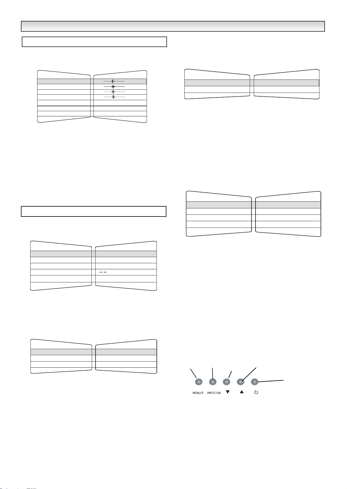
Press the MENU button, then the 2 or 1 button to rotate
and select Picture menu. Set the picture settings for your personal
preference.
Use the 5 or 6 to select eg. Brightness, Contrast, Colour and use
the 2 or 1 button to adjust levels.
Tint : is only available if NTSC equipment is connected.
Text brightness : You can set to minimum, centre or maximum.
Use the 5 or 6 button to select and the 2 or 1 button to set.
To memorise these settings press the OK button. (The OK? will
change to OK.)
To exit press the MENU button.
✐ In PC mode Picture menu is not available.
The preset menu can be used to tune new channels, to reorder
channels and their programme positions, and to make fine adjustments to the tuning.
■ Auto Tuning
1. Press the MENU button and select Preset using the 2 or 1
button. Select Auto Tuning using the 5 or 6 button. The complete line turns yellow.
2. Press the 1 button and select Auto.
3. Press the 1 button to start, all available channels are
automatically stored, starting from programme position 01.
After completing this procedure, the display returns to programme
position “01”.
Position changes sequentially as channels are found.
To cancel this tuning operation, press the MENU button repeatedly.
■ Auto Sort
1. Press the MENU button.
2. Select Preset, press the 5 or 6 button select Auto sort and
press 1.
3. Press the 2 or 1 button to choose either UK or IRE.
4. Press OK to start automatic sorting and storing of TV stations in your
area. It will sort the channels as in Plug and Play (See page 5).
To cancel press Menu button repeatedly.
■ Prog. preset.
This is used to preset a received channel in any desired programme
position.
1. Press the MENU button and select Preset, press the 5 or 6
button and select Prog. Preset.
2. Press the 1 button to enter Semi menu.
3. Select Position by pressing the 6 button. Press the -/-- button
and enter the position (01-99) using the 0-9 buttons or 2, 1
button until the position is selected. (eg: to select position 5 press
0 then 5).
4. Press 5 to highlight Channel. Press the -/-- button (C--) to enter
the number directly if known. (Please refer to the channel table on
page 9).
You can search for a channel for your selected position. Highlight
Channel, press the 2 or 1 button until a channel is found, if
this is not the one required repeat until it is found (C--/H--).
✐
The selection changes colour to blue, to say that another channel
has been found.
5. Press the 6 button and select Memory, press the OK button to
memorise.(The OK? will change to OK).
Press the MENU button to exit.
Controls on the TV Monitor.
Press Button 1 to rotate between Brightness, Contrast, Colour and
Sharpness.
Press
Button 2 to rotate between TV, AV1,RGB, AV2 and PC mode.
Press
Button 3 and 4 to adjust up and down.
Press
Button 5 to switch from display to standby mode (to switch off
completely disconnect from the power supply).
MENU OPERA
MENU OPERA
TION / TV/A
TION / TV/A
V MODE
V MODE
Picture menu
Preset menu
Button 1
Button 3
Button 5
Button 2 Button4
5
1. Press the TV/AV button on your remote control to rotate between
TV, AV1, AV2 and
PC mode.
When PC mode is selected Press the MENU button the following
screen will appear.
2. Press the 2 or 1 button to rotate between Brightness,
Contrast, H-Position, V- Position, H-size, PS and Exit. Select
which mode you wish to adjust and press the OK button.
Set at your desired level by pressing the 2 or 1 button.
3. Press the OK button again to memorise and return to the main PC
mode screen as shown above.
PS mode.
If you select PS mode it will give you two options to choose. POWER
SAVE and AUTO SHUT OFF.
POWER SAVE. If there is no signal being received, after one minute
the display unit switches into Standby mode. If the signal then
becomes available the display unit will automatically switch itself on,
as long as power is still being received.
AUTO SHUT OFF. If there is no signal being received, after one
minute the display unit switches into Standby mode. If the signal then
becomes available you must press the Power button to switch the dis-
play unit on again.
1. Press the 2 or 1 button to rotate between POWER SAVE
and AUTO SHUT OFF.
2. Press the OK button when you have chosen, this will save your
selection.
3. Press the OK button to return to the main PC mode screen.
To Exit the menu rotate by pressing the 2 or 1 button until you
select Exit.
4. Press the OK button to exit.
To manually operate the PC mode. Use the following buttons. They
are located under the blue standby light at the front of your monitor.
1. Press button 2 repeatedly to select PC mode it rotates between
TV, AV1, AV2, and PC mode. This button also works in TV mode.
2. Press button 1 to select the main PC mode screen.
3. Press button 3 or 4 to rotate between Brightness, Contrast,
H-Position, V-Position, H-size, PS and Exit. Select which mode
you wish to adjust and press the button 2. Button 2 has the same
function as the
OK button on the remote control, when in you are
in a menu.
4. Press button 5 to switch the display unit into standby mode. Press
again to switch on.(to switch off completely disconnect from the
power supply).
FM (FUNCTION)
If you have experienced patterning (usually in the form of diagonal
lines across the screen) then select FM. This will give you two
adjustable options. Amplitude (top symbol) and Period (symbol at
right hand side).
Use the level adjustment bars pictured beneath each heading by
pressing the 2 or 1 button, to remove the pattern.
When the patterning has been removed then press exit twice using
the
2 or 1 buttons.
MENU OPERA
MENU OPERA
TION / PC MODE
TION / PC MODE
PC mode
Button 1
Button 3
Button 5
Button 2
Button 4
P
ictur
B
rightn
C
ontrast
C
olou
S
harpness
T
int
T
ex
t brightness
M
emory
Preset
A
uto
T
uning
A
uto sor
P
r
og
.
P
S
wap
F
ine
T
uning
A
uto
C
hannel
P
ositi
on
S
ound
e
ess
r
t
r
ese
t
38
2
27
M
inimu
m
OK? / OK
42
>
>
>
<
>
42
C31
01
s
1
/
/
C
s
entre
2
/ s3
/
M
aximum
/ s4
A
uto
C
ountr
S
tar
t
S
ort
y
42
A
OK
?
S
emi
hannel
C
P
ositi
on
S
kip
M
emory
42
C24
01
OFF / ON
OK?
Page 5

5
1. Press the TV/AV button on your remote control to rotate between
TV, AV1, AV2 and
PC mode.
When PC mode is selected Press the MENU button the following
screen will appear.
2. Press the 2 or 1 button to rotate between Brightness,
Contrast, H-Position, V- Position, H-size, PS and Exit. Select
which mode you wish to adjust and press the OK button.
Set at your desired level by pressing the 2 or 1 button.
3. Press the OK button again to memorise and return to the main PC
mode screen as shown above.
PS mode.
If you select PS mode it will give you two options to choose. POWER
SAVE and AUTO SHUT OFF.
POWER SAVE. If there is no signal being received, after one minute
the display unit switches into Standby mode. If the signal then
becomes available the display unit will automatically switch itself on,
as long as power is still being received.
AUTO SHUT OFF. If there is no signal being received, after one
minute the display unit switches into Standby mode. If the signal then
becomes available you must press the Power button to switch the display unit on again.
1. Press the 2 or 1 button to rotate between POWER SAVE
and AUTO SHUT OFF.
2. Press the OK button when you have chosen, this will save your
selection.
3. Press the OK button to return to the main PC mode screen.
To Exit the menu rotate by pressing the 2 or 1 button until you
select Exit.
4. Press the OK button to exit.
To manually operate the PC mode. Use the following buttons. They
are located under the blue standby light at the front of your monitor.
1. Press button 2 repeatedly to select PC mode it rotates between
TV, AV1, AV2, and PC mode. This button also works in TV mode.
2. Press button 1 to select the main PC mode screen.
3. Press button 3 or 4 to rotate between Brightness, Contrast,
H-Position, V-Position, H-size, PS and Exit. Select which mode
you wish to adjust and press the button 2. Button 2 has the same
function as the
OK button on the remote control, when in you are
in a menu.
4. Press button 5 to switch the display unit into standby mode. Press
again to switch on.(to switch off completely disconnect from the
power supply).
FM (FUNCTION)
If you have experienced patterning (usually in the form of diagonal
lines across the screen) then select FM. This will give you two
adjustable options. Amplitude (top symbol) and Period (symbol at
right hand side).
Use the level adjustment bars pictured beneath each heading by
pressing the 2 or 1 button, to remove the pattern.
When the patterning has been removed then press exit twice using
the
2 or 1 buttons.
MENU OPERA
MENU OPERA
TION / PC MODE
TION / PC MODE
PC mode
Button 1
Button 3
Button 5
Button 2
Button 4
960 x 568
H:48.7 KHz V:59.5 KHz
Page 6

SNOI
T
ACIFICEPS
noitacificeps nommoC
zH05 V042~022 ecruos rewoP
L/L ,I ,K/D ,G/B metsyS metsys noisiveleT
MACES /LAP metsys ruoloC
)edom VA ni 85.3CSTN / MACES /LAP(
21R-1R ,01F-2F ,21E-2E :FHVegarevoc lennahC
,
96-12 :FHU
14S-1S,Z,Y,X:VTAC
mho 57 ecnadepmi tupni laireA
lanimret VA
dradnatSCELENEC :1VA
B
GR
v5
dna BGR ,oe
div etisopmoC :
tup
nI
dradnatSCELENEC :2VA
SHV-S ,BGR ,oediv etisopmoC :tupnI
.tupni oediv etisopmoc CNB ro
C
P :3VA
.tupni C
PA
GV :tupnI
B-3ML2
3EC
1:
0001 oitaR tsar
tno
C
23)sehcni(neercS
)
yllano
gaid
derusaem gniweiv(
)AGXW
(
867 X
663
1
noituloseR yalpsiD
°6
7
1:V
,°671
:H
selgna g
niw
eiV
561 x
015 x
6
18)m
mDxHxW( s
noi
snemiD
)dnats gnidulcni(
14.02)gk( thgieW
6
dn
a tracs h
tob tcennoc ton
od esael
P
.emit emas eht ta CNB
noitacificepS
3
DNA.CNB .AGV ,LAIREA OT TINUYALPSID EHT TCENNOC
.DERIUQER SA SROTCENNOC TRACS
.
1
ot dehcatta rotcennoc eht ot rotcennoc rewop enil-ni eht tcenn
oC
.evo
ba sa tinu yalpsid eh
t
.teltuo llaw a ot tinU yalpsiD eht fo droc rewop eht tcennoC .2
esaelp ,hctiws ffO/nO sniam a evah ton seod tcudorp siht sA
.elbissecca ylisae si gulp sniam ruoy erusne
,V042~022CA egatlov sniam a rof deraperp si tinu yalpsid ehT
si tes VT eht nehw ro ,sniam eht ffo hctiws yletelpmoc oT .zH05
-sid ot elbasivda si ti ,emit fo doirep dednetxe na rof desu eb ot ton
eht tcennocsid ro teltuo rewop eht morf droc rewop eht tcennoc
.relpuoc sniam
:gni
nraW
.3
tinu
eht ,yr
ujni tneverp oT tsum ot dehctatta yleruces
eb
.snoitcurtsni noitallatsni eht h
tiw
ecnadrocca ni
ll
aw eht
rof ffo tinu yalpsid eht gnihctiws rof desu si edom ybdnatS ehT
si tub ffo dehctiws si tinu eht edom ybdnats nI
.em
it fo sdoirep trohs
,edom ybdnats otni tinu y
alp
sid eht nrut oT.rewop sniam gniviecer llits
eht sserp n
ottub .
eht sserp e
dom
ybdnats ni neh
W
nottub .yalpsid eht no hctiws ot
eht no skram "-" dna "+" eht taht os seirettab tlov 5.1 "AA" owt llatsnI
etomer eht otni tinu eht edisni skram "-" dna "+" eht hctam seirettab
.tesdnah lortnoc
.noitcnuf
unem eht hguorht dellortnoc era serutaef stinu ru
oy fo
ynaM
hcihw swohs neercs eht fo mottob eht ta rab a noitarepo unem gniruD
.desu eb nac slortnoc
eht s
serP
ot nott
ub
retne dna
tixe
sunem bus 5 eht
,
erutci
P
gnitteS ,remiT ,dnuoS dna teserP .
r
uoloc sti d
na deyalpsid era snoitpo sti detceles si unem bus a n
eh
W
.wolley ot e
gnahc lliw
e
ht sserp rehtie nac uoy unem buS hcae tes evah uoy nehW UNEM
nottu
b
e
hts
serp
ro n
eercs eht
ra
elc dna tixe o
t
nottub
e
ht litnu
eht gnisU .detceles-er si unem bus
r
o nottub
n
ac uoy
.
niaga etato
r
gnittes remit-ff
O
e
dom
yb
dnats eht otni rotinom yalpsid eht hctiws
lliw
remit ffO ehT
.despale sah emit detc
eles eh
t nehw
.1 eht sserP
nottub UNEM tceles
dna remi
T gnisu ro -tub
not
tceleS.
re
miT FF
O
gnisu ro nottub enil etelpmoc ehT .
.wolley s
nrut
.2
eht sser
P
r
o
nottub .)wolle
y de
thg
ilhgih( --:-- tceles o
t
.3
eht sser
P
r
o nottub .emit egnahc o
t
.srh00:2 si emit mumixam ehT.spets etunim 03 ni segnahc emit ehT
.4
eht sser
P
r
o
nottub
.)wolley( enil ete
lpmoc thg
ilhgih o
t
.5 eht sser
P
K
O
nottub .sgnittes ruoy erots
ot
-inom yalpsid eht erofeb etunim eno neht ,remit ffo eht tes
ev
ah uoy fI
.neercs eht no sraeppa yalpsid a ,ffo sehctiws rot
eht yb ffo dehctiws si rotinom eht fI nottub ybdnats eht no
hct
iws y
bdnat
s eht yb ro lortno
c e
tomer thgir eht htaenrednu
.del
lecnac eb lliw sgni
ttes re
mit
eht ,rot
inom eht fo tnorf
eht sserP nottub
UNE
M eht sserp ro ,tixe ot nottub thgilhgih ot
eht sserP neht dna wolley enil etelpmoc nottub .re
mit
mralA tes ot
T
SNI
TSNI
A
LL
A
ALLA
N
OIT
NOIT
)laitnessE( snoitcennoC 1 : petS
!GN
IN
RAW fo noitarep
o e
ht ni desu era segatlov hgiH
.le
nno
srep ecivr
es deifilauq ot ecivres refeR .tes siht
noitallat
sn
i yretta
b l
ortn
o
c
eto
m
eR 2 : petS
AREPO UNEM
AREPO
U
NEM
N
OI
T
N
O
IT
yromem
erutciP
UNEM
dnuo
S
remiT
gninuT eniF
teserP
tinu rot
inom siht
n
i desu
toN
re
mit FF
O
re
mit mralA
remiT
.
ge
u
n
e
m re
m
i
T
- - : -
-
remiT
remit mr
alA
remit FFO
- - : - -
?K
O
N
I
TUO
SNOITCENNOC CNB
AGV /
CP
snoitisop gnixif tnuom
ll
aW
2VA 1VA
t
racS
snoitcennoc
rotcennoc enil-nI
ni lairea laixaoC
KNISTA
EH
E
VO
MERTON OD
Page 7

7
END-USER LICENCE & SERVICING
END-USER LICENCE & SERVICING
The product (meaning the equipment or appliance to which this
documentation relates) incorporates Software (the software applications, utilities and modules embedded within the Product) which is
owned by Sanyo or its licensors. Before using the product, please
read the End-User Licence Conditions detailed below. If you do not
agree to the terms and conditions of the End-User Licence, Please
do not proceed to use the Product- repack the Product unused and
return it to your supplier together with proof of purchase for a full
refund. By using the product, you agree to be bound by the terms
and conditions of the End-User Licence.
Licence Grant, Conditions and restrictions
1. Sanyo grants you a non-exclusive, world-wide (subject to export
controls), non-transferable (except as permitted by 2 below),
royalty-free licence to use the Software upon and with the Product.
2. You may not transfer any of your licence rights in the Software
without the prior written consent of SANYO and if consent is
provided then the Software shall only be transferred in conjunction
with the transfer of the Product AND provided that the transferee
has read and agreed to accept the terms and conditions of this
licence.
3. You must ensure that the copyright, trademark and other protective
notices contained in the Software are maintained and not altered
or removed.
4. The Software provided hereunder is copyrighted and licenced (not
sold). SANYO especially does not transfer title or and ownership
rights in the Software to you. The Software provided hereunder
may contain or be derived from portions of materials provided to
SANYO under licence by a third party supplier.
5. Except as expressly permitted by statute you may not;
● use the Software in conjunction with any other computer
hardware other than the product;
● copy all or part of the Software;
● incorporate all (or any of) the Software into other programs
developed by (or on behalf of) you and/or used by you;
● reverse-engineer, decompile or disassemble the Software;
● make the Software (or any part of it) available, or permit its
redistribution, for use with any computer hardware other than
the Product; or rent, lease, gift, loan, sell, distribute or transfer
possession of the whole or any part of the Software.
Termination
This licence is effective until terminated. This licence will terminate
automatically without notice if you fail to comply with any of its
provisions.
Disclaimer
1. The Software is(to the extent permitted by law) supplied ‘as is’ and
SANYO and its suppliers expressly exclude all warranties, express
or implied, including (but not limited to) warranties of satisfactory
quality, fitness for purpose and non-infringement (save to the
extent that the same are not capable of exclusion at law).
2. In no circumstances will SANYO be liable for any direct, indirect,
consequential, or incidental damage (including loss of profits,
business interruption, loss of data or the cost of procurement of
substitute goods, technology or services) arising out of the use or
the inability to use the Software (save to the extent that such
liability is not capable of exclusion at law).
General
1. This End-User Licence will be governed by laws of England and
the User may only bring claims in the English Courts and SANYO
shall be entitled to bring a claim in the courts of any jurisdiction.
2. The above terms and conditions supersede any prior agreement,
oral or written, between you and SANYO relating to the Software.
End-User Licence
Your display unit is fully transistorised and does not contain any user serviceable components.
You must not remove the rear cover of the display unit by yourself. The apparatus is working with high voltages and could damage
objects or even endanger people. Leave all required repair and service jobs to an authorised service technician. He will exclusively
use such spare parts that are complying with the same safety standards as applicable to the original parts. The use of original spare
parts can prevent fire, shock and other hazards.
Unplug the display unit from the wall outlet and refer servicing to qualified service personnel under the following conditions:
■ If the power cord or plug is damaged.
■ If liquid has been spilt into the display unit receiver.
■ If display unit has been exposed to rain or water.
■ If the display unit has been dropped or the cabinet has been damaged.
■ If the display unit exhibits a distinct change in performance.
■ If the display unit does not operate normally by following the operating instructions.
Adjust only those controls that are covered in the operating instructions as improper adjustment of other controls may result in damage. This will
often require extensive work by a qualified technician to restore the
display unit
to normal operation.
Servicing
Page 8

8
JM2N
A-4520P1P6AK1 .oN
tra
P
EC 3ML2
3 B
-
.ti
n
u y
al
psi
d
ruoy gnis
u
e
ro
f
eb koob
n
oi
tc
u
rt
s
nI siht
d
a
er e
s
a
elP
t
in
U
y
alps
iD
LAUNA
M
N
OITCURTSN
I
 Loading...