


SPECIFICATIONS
Dimensions
weight
Water quantity (HIGH)
( )
Power Source
Power Consumption
Required Water Pressure
575(W) x 597(D) x 980(H) mm(ASW-U94HTP)
580(W) x 556(D) x 980(H) mm(ASW-U94HT)
( ) ( ) ( )
35 kg
52 litres
AC Local voltage
,
340 W
0.03 Mpa ~ 0.8 MPa
(0.3 kgf/cm2 ~ 8 kgf/cm2 )
FOR WASHER WITH A 10 Amp. PLUG TOP 3 PIN
13
WARNING - This appliance must be earthed.
IMPORTANT
The wires in this mains lead are coloured in accordance with the following code:
Green/yellow: Earth
Blue: Neutral
Brown: Live
As the colours of the wires in the mains lead of this appliance may not correspond
with the coloured markings identifying the terminals in your plug, proceed as follows:
The wire which is coloured green and yellow must be connected to the terminal
in the plug which is marked with the letter E or by the earth symbol  , or coloured green or green and yellow.
The wire which is coloured blue must be connected to the terminal which is marked with the letter N or coloured black.
The wire which is coloured brown must be connected to the terminal which is marked with the letter L or coloured red.
:
:
:
:
:
E 
N
L
|
ASW-U94HTP |
|
ASW-U94HT |
MICROCOMPUTER CONTROL
FULLY AUTOMATIC WASHING MACHINE
Before operating this washing machine, please read these instructions carefully and completely.
CODE NO.301-6-421S-751-40-A |
SANYO Electric Co.,Ltd. |

CONTENTS
FEATURES |
2 |
WARNINGS |
2 |
ACCESSORIES |
3 |
NAME OF PARTS |
3 |
INSTALLATION INSTRUCTIONS |
4-8 |
NAMES AND FUNCTIONS OF CONTROL PANEL |
9-10 |
NORMAL USAGE |
11 |
HOW TO USE THE CUSTOMIZED COURSE |
12 |
COURSE CHOOSING GUIDE |
13 |
HOW TO USE THE BLANKET COURSE |
14 |
VARIOUS FUNCTIONS |
15-16 |
PRESET |
15 |
WATER LEVEL SETTING |
15 |
MULTIPLE WATER POWER FUNCTION |
15 |
SHOWER RINSE |
15 |
REMEMBER FUNCTION |
16 |
CHILD LOCK FUNCTION |
16 |
TWO CLEAN STEPS FUNCTION |
16 |
HOW TO DRAIN REMAINING WATER |
16 |
DELETE THE END BUZZER |
16 |
TROUBLE SHOOTING GUIDE |
17 |
NO TROUBLE CONDITIONS |
18 |
CARE AND MAINTENANCE |
18 |
SPECIFICATIONS |
Back Cover |
FEATURES
·Ultrasonic washing function: completely clean the dirty.
·Digital display: easy operation.
·Soft Spin: Anti-crease spin .
·Custom course and remember function.
 WARNINGS
Never put your hand(s) into the Wash/Spin Tub while the washer is operating.
·If you reach into the Wash/Spin Tub, it can cause injury.
·If the Wash/Spin Tub dose not stop within 15 seconds after
the Washer Lid is opened,
turn the washer off immediately and call
a service person.
Be sure not to bring any type of flame near the washer or put
lit cigarettes or volatile materials on the top of the washer. ·It may deform the washer
or catch fire, because this washer has a large number of plastic parts.
Do not install the washer in
the bathroom or very humid 


 place.


 ·It may cause a


 malfunction or an


electric shock.
Be sure not to splash or pour water on the Control Panel. ·It may cause a malfunction
or an electric shock.
Be sure to connect Power Plug and Power Cord properly.
·Be sure to plug the Power Cord into a proper socket-outlet for the washer.
·An improperly attached plug may catch fire.
·Never disconnect by pulling the cord. Hold the plug as you pull it out.
·Never use a damaged Power
Cord.  ·Never connect and/or disconnect
the Power Plug with wet hands, it may cause an electric shock.
Never wash items stained with
benzine, kerosene, thinner or gasoline. ·It may cause a risk of fire
or explosion.
Do not allow children to play on or in the washer.
·If a child accidentally falls in to the Wash/Spin Tub, serious injury could occur.
Do not allow your washer to be repaired by an unqualified service person.
·It may cause a risk of accidental fire.
·If the washer operates abnormally, it may cause injury.
1 |
2 |

ACCESSORIES
“Magic” Hose Joint
(Only for ASW-U94HTP)
(Only for ASW-U94HT)
NAME OF PARTS
Water Supply Hose
Washer Lid
Softener Dispenser
Lint Filter
Contro l Panel
Wash/Spin Tub
Frame
Adjustable Leg
(One)
3
Faucet
(Close water supply after operation)
Power Plug
Power Cord
Detergent Tray
Pulsator
Leg
INSTALLATION INSTRUCTIONS
Installing the Bottom Cover |
|
|
1.Unplug the Power Cord of the washer. |
Bottom |
|
2.Gently lay down the front side of washer on a soft mat or |
Cover |
|
cushion.(Becareful not to dent the Frame.) |
Screw |
|
|
||
3.Insert the attached Bottom Cover into the hooks of Leg |
Front |
|
by straightly pushing until it reaches into the front hooks. |
||
|
||
4.Fasten the Bottom Cover with a screw. |
Leg |
|
5.Gently set the washer upright. |
||
|
||
Location of Washer |
Back |
|
|
1.Choose a dry location out of sunlight for the washer. 2.Install the washer on a stable and level surface.
Inclined floor |
Unstable floor |
3.Adjust the Adjustable Leg of washer if necessary to make the washer level as shown in the figure.
● The maximum permissible inclination of the supporting surface is 2 .
Fundus
Lock Nut
Tighten 
 Loosen
Down 
 Up
Up
Adjustable Leg
CAUTION:
●Do not block the ventilation openings on the bottom of washer by carpeting when the washer is installed on a carpeted floor.
Attaching the "Magic" Hose Joint to a Faucet
Faucet: Type A :is the most suitable
Type A |
Type B |
Type C |
|
At least 16mm |
Water leak |
Type B :The length of the mouth of the faucet needs to be at least 16mm. If it is less than16mm, the"Magic"Hose Joint can not be installed.
Type C :It may cause water leaking.
CAUTIONS:
●Do not use water which is hotter than 50 .
●If your faucet is not suitable, please consult your dealer.
4

INSTALLATION INSTRUCTIONS
How to Attach the “ Magic ” Hose Joint
1.Loosen the four screws and slide the top of the "Magic"Hose Joint(section A in the figure)onto the faucet. Then, securely tighten the four screws provided with the “Magic" Hose Joint by using a screwdriver to secure the top of the joint to the faucet.
2.Remove the CAUTION label from the "Magic" Hose Joint.
3.Turn the male coupler on the joint (section B in the figure) clockwise to attach it securely to the top of the joint (section A in the figure).
●The appliance is to be connected to the water mains using new Water Supply Hose and “Magic" Hose Joint and old hose-sets should not be reused.
Screw |
A |
After tightened |
|
||
|
|
About 4mm |
CAUTION |
B |
(About 2mm or less) |
label |
|
|
CAUTIONS:
If outer diameter of faucet is larger than calibre of the Joint Ring, loosen the four screws and remove the Joint Ring from the "Magic" Hose Joint.
Joint Ring
Installing Water Supply Hose to the Washer
1.Turn the nut clockwise while holding the hose. Turn the nut counterclockwise after turning the faucet off when you want to detach the Water Supply Hose.
Nut
Hose
2.While pushing the sleeve on the female coupler (section D in the figure) of the joint down with your fingers, connect the female coupler to the male coupler (section C in the
figure).
C 
Lock Lever

 Sleeve
D
3.Release the sleeve, then push the Water Supply Hose up into the “ Magic ” Hose joint until it clicks into place.
4.Pull the Water Supply Hose down to make sure that it is securely attached.
INSTALLATION INSTRUCTIONS
How to Detach the Water Supply Hose
1.Turn the faucet off.
2.Press the POWER ON/OFF button to turn the power on, the NORMAL button and the START/PAUSE button.
3.Press the POWER ON/OFF button to turn the power off 15 seconds later.
4.While pushing the lock lever and the sleeve on the female (section D in the figure) of the joint down with your fingers, detach the female coupler from the male coupler (section C in the figure).
C 


Sleeve
Lock
Lever
5.Turn anti-clockwise the water inlet hose on water inlet valve till taking it down.
Nut

 Hose
Hose
How To Installing The Drain Hose (Only for ASW-U94HTP)
1.Pinching the two bands of the clamp on the drain hose, connect it to the drain valve (rear to cabinet) and fix the hose band.
2.Pull the Drain Hose upward and fix it to the hose clip on back over of cabinet. 3.Hang the drain hose to the hole on right side of top frame when the washer is not
working. And put the drain hose to drain spout when washer start working.
CAUTION:
Please make use the height of drain hose is not less than 700 mm during operating, otherwise, the washer won’t work. 

5 |
6 |

INSTALLATION INSTRUCTIONS
Installing The Drain Hose (Only for ASW-U94HT)
Set the clip part of Hose Band sideways to prevent touching the frame which may cause a vibration noise. 


Drain Outlet


 Drain Hose
Hose Band
Changing the Drain Hose Direction (Only for ASW-U94HT)
You can change the direction from right side to left side.
NOTE:
Put gloves on to prevent injury of your hands when changing the Drain Hose direction.
1.Unplug the Power Cord of the washer. 2.Detach the Back Cover by loosening screws at the back side of the washer.
Detach outer Drain Hose and gently lay down the front side of washer on a soft mat or cushion.
●Be careful not to open the Washer Lid and dent the frame.
3.Detach the Cap from the left side of frame. 4.Loosen the Hose Band and pull the inner Drain Hose out of the Drain Valve. Pull the Hose Band out of the inner Drain Hose.
5.Remove right and left Tabs of Drain Outlet one side by another side pushing the Tabs both in side and outside and pull the Drain Hose out toward outside of frame.
6.Let the inner Drain Hose through outside of left hole and set the protrusive guard of inner Drain Hose to the square cutting part of frame, then attach the Drain Out let of the hose until fitting the Tabs certainly to the frame.
7.Connect the inner Drain Hose to the Drain Valve in place and fix the Hose Band as shown below.
●if you do not attach correct position marked with ,it can damage the inner Drain Hose and cause a water leaking through the torn position.
8.Attach the Cap to the right hole.
9.Reattach Back Cover and gently set the washer upright.
7
INSTALLATION INSTRUCTIONS
Drain Valve
Hose Clip
Drain Hose
 Drain hole
Drain hole cover
Drain Valve |
|
Drain Hose Hose Clip |
Drain hole |
Extension of the Drain Hose (Only for ASW-U94HT)
When extending the external Drain Hose, please follow the below figure for the length and height.
Extension Hose |
|
Height |
Length |
|
|
|
|
|
|
No straight |
Max.15cm |
Max.1m |
||
|
|
|
|
|
Straight |
|
|
|
Max.3m |
|
|
|
||
|
|
|
|
|
|
Max.1m |
Max.15cm |
||
|
|
|||
|
|
|
|
|
|
|
|
|
|
|
|
|
|
|
|
|
|
|
|
8
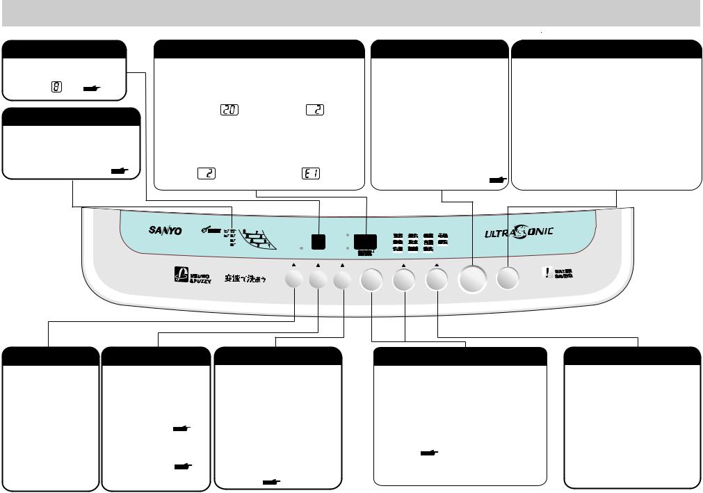
NAMES AND FUNCTIONS OF CONTROL PANEL
WATER LEVEL Indication
●This indicator shows water
level.
(E.g.)
11
DETERGENT Indication
●These are the spoon indications of the DETERGENT volume.
●Refer to "DETERGENT AND LOAD RECOMMENDATIONS" onpage11.
11
TIMER And PRESET Indicators
● This indicator shows |
● This indicator shows when |
||||||
remained time during |
the washing is finished |
||||||
washing. |
during presetting. |
||||||
(E.g.) |
Remaining time is 20 minutes |
|
(E.g.) |
Finish washing 2 hours later |
|
||
REMAINING TIME…… |
|
|
|
|
|||
● When setting SELECT, |
● When abnormal conditions |
||||||
the digital display indicates |
occur, the indicator will |
||||||
time or times. |
indicate warning. |
||||||
(E.g.) |
Twice Water Saver Rinse |
|
(E.g.) |
Water does not flow |
|
|
|
|
REMAINING TIME |
|
|
SOFT SPIN |
CHILD LOCK |
|
|
|
START/PAUSE Button |
POWER ON/OFF Button |
●This button can be use to start the washer operation.
●This button can also be used to temporarily stop the washer operation.
To restart the washer operation, press the START/PAUSE button again.
NOTES:
●This is not a cancel button.
●If you want to delete the End Buzzer, press the START/PAUSE button and hold down for about 4 seconds until beeping stops.
Detailed please refer to Page16. 16
To turn the power on, press the POWER ON/OFF. When you want to turn off the power, press the POWER ON/OFF again.
When washing has finished, the power will be turned off in 5 seconds automatically.
( except Setting Remained water Draining function).
NOTES:
●If you want to change the wash course, turn the
POWER ON/OFF off and then on it again.
●If you leave the washer turning on without starting the operation, the power will be turned off in 10 minutes by itself.
MIN. |
PRESET |
R I N S E |
NORMAL |
BLANKET |
W |
G |
|
|
|
|
|
N |
|
|
S O A K |
S P I N |
CUSTOM |
DELICATE |
|
A S HI |
HRS. |
|
|
||||
|
|
|
|
|
|
|
|
W A S H |
ULTRASONIC |
HEAVY DUTY |
|
|
|
|
|
|
|
SOFT SPIN Button
Press the button SOFT SPIN , the light above flashes. The last 2 minutes spinning will be soft spin, this avoid clothes creasing.
WATER LEVEL Button
CHILD LOCK Function
●You can choose the appropriate water level that matches the load size.
●Different water levels for washing rinsing optional. Detailed operation please refer to Page 15.
15
●You can set CHILD LOCK function. Refer to CHILD LOCK function at page 16.
16
SOFT |
|
|
S E T |
SELECT |
COURSE |
START |
POWER |
|
WATER |
VARIABLE |
|
||||||
ON/OFF |
||||||||
SPIN |
LEVEL |
WASH |
|
|
|
PAUSE |
/ |
|
|
|
|
|
|
|
|
|
|
|
|
|
|
|
VARIABLE WASH Button |
SELECT And SET Button |
Press VARIABLE WASH button to adjust water power during washing or rinsing.
Neuro & fuzzy function will not be effective when select this function.
And this function could not be set for DELICATE or BLANKET course.
●The SELECT and SET button can be used to select PRESET, SOAK, WASH time, RINSE times, and SPIN time.
For example to set Rinse times: Press SELECT button till RINSE light flashes. Then press SET button to choose you wanted rinse times.
Detailed operation please refer to Page 12. 12
COURSE Button
●To choose the washing course, press COURSE button. Press it and choose you need course, then the light above flashes.
Detailed please refer to
Page 15. 15
9 |
10 |
 Loading...