


SCC2600A
SCC 2600A

1
SANY CRAWLER C RANE
SCC2600A
1
SCC2600A
CONTENTS
SCC2600A Crawler Crane
Outline Dimensions
Main Technical Features
Main Performance Data
Transport Dimensions
Transporting scheme
Assembly and disassembly diagram
Specifi cations
Superstructure
Undercarriage
Operation Devices
Safety Devices
Operating Condition Combination
Operating Condition Combination
H Operating Condition
Fixed Jib Combination
Luffi ng Jib Combination
Shield Operating Condition Load Charts
P2
P16
P23
02 Outline Dimensions
03 Main Technical Features
04 Main Performance Data
05 Transport Dimensions
10 Transporting scheme
12 Assembly and disassembly diagram
CRAWLER CRANE

SANY CRAWLER C RANE
SCC2600A
3
2
Main technical featuresOUTLINE dimensions
1. Safety Control System:
There are two convenient a nd reliable operation modes, wor king
and assembly. The electronic level indicator and bubble level
indicator are equippe d to ensure dual protection for real- time
display. It has the leaving-machine stop action, emergency
electrical c ontrol, lightning protection, walkin g automatically
steering and closed circuit monitoring functions, with the
complete safety and mo nitoring system;
2. New Lift Operating Condition De sign:
The operating condition of 20m boom + 12m heavy fixed jib is
adopted, to meet the lift ing requirement of shield machine used
for subway construction and similar products. The turning-over
operation of shield mac hine can be automatically done, without
the auxiliary cra ne. The auxiliary hook is larger enou gh to lift the
heavy object up to 96T. The load moment limiter indicator can
dynamically reflect the loading capacities of main and auxiliary
hooks;
3. Beautiful and Comfortable Cab:
The cab is beautiful, c omfortable and safe;
4. Superior Operating Performance:
The load sensor, limit load regul ation and electronic- over-
hydraulic control can ens ure the best all actions excellent action
and stability.;
5. Reliable Function Assurance:
The designed safety margin for structures and mechanisms are
sufficient; and th e control system can operate stably in the cold,
high temperature, plateau, and l arge sand harsh environment;
6. Convenient Maintenance Technology:
It takes approx imately no more than 10m in/person to adjust;no
more than 30min/person for daily maintenance;no more than 2h/
person to repair.GPS remote monitor ing system is optional for
maintenance and management.;
7. Powerful Lifting Capacity:
The maximum boom lif ting moment is 183.8t × 8m = 1470.4t
• m and the longest boom length is 86m; th e maximum lifting
capacity of luffing jib is 62.5t × 18m = 1125t • m and the longest
boom combination length is 62 m+6 3m;
8. High Efficient Self-Handling Technology:
A button can be coc ked to easily lift the mast, to ensure the
clutch traction wi nch reeving operation. It can suppor t the
machine self-dis mounting operation; and the quick-cha nge rope
connectors and win ch rope head are can be used;
9. Large Chassis Design:
The chassis wi th the track gauge of 6.7m is ado pted, to ensure
the excellent operation sta bility within the range of 360°
rotation;
10. Globalization of Transportation Standards:
The transport wei ght of main machine is limited within 45 tons,
the transport wi dth is less than 3m and the transpor t height is
less than 3.2m, thus saving the transport cost significantly;
11. Powerful Traveling Capacity with Load:
The powerful travelin g traction and walking stabilit y can make
the best advantage of craw ler crane;
12. Reliable Transmission System:
The use of advanced hydraulic co mponents and of load
feedback control technology with independent property rights
can ensure the stable an d reliable operation of hydraulic system;
13. Large Fuel Tank Design:
The fuel tank capaci ty is 1050L, which is greatly incr eased
compared with the o ld models (400L), thus avoid the frequent
refueling;
14. Broad Adaptability:
In accordance with Europe and America non-road phase III
emission standards a nd has a wide application in boat building,
subway constructio n, metallurgy and infrastructure.
9145
8003
1200
1200
7980
7504
3164
10000
4622
1800
2350
1400
1550
369
3033

SANY CRAWLER C RANE
SCC2600A
5
4
Main Performance Data Tr a ns p o rt Dimensi o ns
L
H
L
H
L
L
L
L
L
H
H
H
H
H
Basic Machine ×1
Length 13.32 m
Width 3.0m
Height 3.20m
Weight 45t
Track Assembly ×2
Length 9.15 m
Width 1.20 m
Height 1.4 0m
Weight 22t
Boom Head (inclu ding pulley block) ×1
Length 3.24m
Width 2.0 7m
Height 1.6 2m
Weight 3.5t
Boom Base (inclu ding winch) ×1
Length 10.35m
Width 2.60m
Height 2.99m
Weight 13.58t
3m Boom Inser t ×1
Length 3.18 m
Width 2.65m
Height 2.66m
Weight 1. 3t
6m Boom Inser t ×1
Length 6 .18m
Width 2.65m
Height 2.66m
Weight 2.0t
12m Boom Insert ×5
Length 1 2.18m
Width 2.65m
Height 2.66m
Weight 3.6t
Main Performanc e Parameters of SCC2600A Crawler Cran e
Performance index Unit Parameters
Boom operating
condition
Maximum lifting capacity
t 260
Maximum rated lif ting moment
t•m
1470.4
Boom length m 20~86
Boom luffing angl e ° 30~85
Fix jib operating jib
Longest boom + longest fi xed jib m 62+42
Fixed jib offset angle ° 10, 30
Heavy fixed jib
operating condition
Boom + fixed jib (shield operating
condition)
m 20+12
Angle between boo m and jib ° 20
Luffing jib operat ing
condition
Maximum liftin g moment t•m 62.5×18 =1125
Longest boom + longest l ufffing jib m 62+63
Jib luffing angle ° 65~88
Speed
Boom ( jib) winch line speed (outmost
working layer)
m/min 0~124
Main luf fing winch lin e speed (outmost
working layer)
m/min 0~108
Auxiliary luf fing winch line speed
(outmost working layer)
m/min 0~14 4
Swing speed rpm 0~1. 25
Traveling speed km/h 0~1.2/0~0.53 (double speed)
Gradeability % 30
Engine
Output power kW 242
Rated speed rpm 2100
Transportation data
Max. transpor t weight of single part
(including boom and jib li fting winches)
t 45
Transport dimension (L * W * H) mm 13320×3000×3200
Average ground pressure MPa 0.14

SANY CRAWLER C RANE
SCC2600A
7
6
Tr a ns p o rt Dimensi o nsTr a ns p o rt Dimensi o ns
6m Transitional Boo m Insert ×1
Length 6.20m
Width 2.65m
Height 2.66m
Weight 2.0t
Luffing Jib Tip ×1
Length 6.46m
Width 2.12m
Height 2.1 0m
Weight 2.4t
3m Luffing Jib In sert ×1
Length 3 .17m
Width 2 .12m
Height 1. 91m
Weight 0.63t
6m Luffing Jib I nsert ×1
Length 6.17 m
Width 2.12m
Height 1. 91m
Weight 1.04t
6m Luffing Jib I nsert ×1
Length 6.17 m
Width 2.12 m
Height 1. 91m
Weight 1.05t
12m Luffing Jib Inse rt ×3
Length 12.1 7m
Width 2.12 m
Height 1. 91m
Weight 1.95t
Boom Extens ion ×1
Length 2.2m
Width 0.9 5m
Height 1. 44m
Weight 0.42t
Jib Base, Luffing Front and Rear Masts ×1
Length 11. 49m
Width 2 .11m
Height 3.26m
Weight 5.5 t
6m Fixed Jib Inser t ×1
Length 6.11 m
Width 1.50 m
Height 1. 42m
Weight 0.75t
11.5m Fixed Jib Insert ×2
Length 11.67m
Width 1.5 0m
Height 1.42m
Weight 1.3 t
Fixed Jib Base and Ma st ×1
Length 6.70 m
Width 1. 42m
Height 2.00m
Weight 1.75t
Fixed Jib Tip ×1
Length 7.1 0m
Width 1. 42m
Height 1. 43m
Weight 1.75t
Carbody Counterweight ×2
Length 5.48m
Width 1.72 m
Height 0.60m
Weight 15t
Counterwe ight Tray ×2
Length 7. 50 m
Width 1.9 6m
Height 0 .70m
Weight 16t
L
L
L
L
L
L
L
W
H
H
H
H
H
H
L
H
W
H
H
H
H
W
L
L
L
L
L
L

SANY CRAWLER C RANE
SCC2600A
9
8
Tr a ns p o rt Dimensi o nsTr a ns p o rt Dimensi o ns
16t Hook ×1
Length 0.53m
Width 0 .57m
Height 1.10 m
Weight 0.9 t
6t Counter weight Block ×14
Length 2.17 m
Width 1.9 6m
Height 0. 51m
Weight 6t
Dolly ×1
Length 2.56 m
Width 1.74m
Height 1.00 m
Weight 1t
260t Hook ×1
Length 1.04m
Width 1.02 m
Height 2.93m
Weight 5.2t
160t Hook ×1
Length 0.59m
Width 1.02 m
Height 2.64m
Weight 3.2t
100t Hook ×1
Length 0 .51m
Width 1.02 m
Height 2.48m
Weight 2.3t
50t Hook ×1
Length 0.45m
Width 1. 02m
Height 2.30m
Weight 1.7t
H
H
H
H
H
W
L
L
L
L
L
L
W
W
W
W
H
L
W
Notes: 1. The transp ort dimensions of t he parts are marked o n schematic
diagrams, but not d rawn by scale; the dime nsions indicated ar e
the design value s excluding packag e.
2. The weight is the d esign value and th ere may be differe nce due
to the manufactu ring error.

SANY CRAWLER C RANE
SCC2600A
11
10
Transporting schemeTransporting scheme Transporting scheme
Platform lorry 498-16165 Rated load:49. 8t
Transport part Basic crane
Transport weight 45t
Quantity 1
Platform lorry 395-16165 Rated load:3 9.5t
Transport part Left track fra me assembly
Transport weight 22t
Quantity 1
Platform lorry 395-16165 Rated load:39.5t
Transport part Right track fra me assembly
Transport weight 22t
Quantity 1
Platform lorry 20-146 30 Rated load:20t
Transport part
Counterweight tray × 1, 6m luffing jib inter mediate
section Ⅰ and 6m luffing jib intermedi ate section
Transport weight 17.7t
Quantity 1
Platform lorry 20-146 30 Rated load:20t
Transport part
Central ballast frame × 1, 6m boom intermediate secti on
× 1 and 3m luffing jib intermed iate section × 1
Transport weight 18t
Quantity 1
Platform lorry 20-146 30 Rated load:20t
Transport part
Transport part : Counterweig ht block × 2 and 12m boom
intermediate section × 1
Transport weight 15.7t
Quantity 5
Platform lorry 20-146 30 Rated load: 20t
Transport part
Counterweight block × 2, 12m luffing jib int ermediate
section × 1 and 50T hook × 1
Transport weight 15.2t
Quantity 1
4117
2460
2460
4346
4844
4619
3916
859
9146
9146
6000
6000
13115
13115
3227
3227
18018
18018
14630
14630
14630
14630
2840
6480
8500
13320
13115
3450
18341
1000
1060
1060
1500
1500
1500
1500
1000
500
1000
1000
1000
1000
1840
3800
3860
1023
Platform lorry 20-146 30 Rated load:20t
Transport part Basic crane
Transport weight 13.5t
Quantity 1
Platform lorry 20-146 30 Rated load:20t
Transport part
Central ballast frame × 1, 12m luffing jib intermediate
section × 1 and 16T ball hook × 1
Transport weight 18t
Quantity 1
Platform lorry 20-146 30 Rated load:20t
Transport part Fixed jib 11.5m and intermediate se ction × 1
Transport weight 1.3t
Quantity 2
Platform lorry 20-146 30 Rated load:20t
Transport part Fixed jib base and mast × 1, fixed jib top × 1
Transport weight 2.6t
Quantity 1
Platform lorry 20-146 30 Rated load:20t
Transport part
160T hook × 1 and boom tape red insert ×1, Boom head
(with pulley bloc k) × 1 and luffing jib top × 1
Transport weight 13t
Quantity 1
Platform lorry 20-16140 Rated load:20t
Transport part
Luffing jib base and front and rear mast assembly × 1, 100T hook
× 1, 260t hook × 1 and fixed jib 6m int erme diat e sect ion × 1
Transport weight 13.5t
Quantity 1
Platform lorry 20-1614 0 Rated load: 20t
Transport part
Boom base × 1, boom 3m int ermediate sect ion × 1,
boom extensio n × 1 and dolly × 1
Transport weight 16.7t
Quantity 1
3916
3916
3454
3768
4062
4214
3932
1500
1500
1500
1500
990
990
990
1000
1000
1000
500
500
500
2950
7440
600
16140
16140
16140
3390 1000
1840
6590
9500
14630
14630
14630
14630
7717

SANY CRAWLER C RANE
SCC2600A
13
12
Assembly and disassembly diagram Assembly and disassembly diagram
1) Basic crane self-assembly
2) Track frame self-assembly
3) Counterweight self-assembly
4) Boom/jib base self-assembly
1) Basic boom installation
Main/Auxiliary winch wire rope
2) Jib frame installation under luffing jib operat ing condition
Boom frame installation diagram

SANY CRAWLER C RANE
SCC2600A
15
14
15
SCC2600A
Superstructure 16
Undercarriage 18
Operation Devices 19
Safety Devices 20
3) Jib frame installation under fi xed jib operating condition
Assembly and disassembly diagram

SANY CRAWLER C RANE
SCC2600A
17
16
NO.1 Main lifting device
Outermost working layer rope speed 0~ 110 m/ min
Diameter of wire rop e 28 mm
Length of wire rope of b oom winch 480m
Rated single line pul l 17t
NO.2 Auxiliar y lifting device
Outermost working layer rope speed 0~ 110 m/ min
Diameter of wire rop e 28 mm
Length of wire rope of b oom winch 390m
Rated single line pul l 17t
1)Engine
■
Diesel engine with r ated power of 242kw (324hp)/2100rpm
and rated torque output 1424N·m/1500rpm.
■
Emission standard: Tier I II .
2)Electrical Control System
■
Advanced central co ntrol unit, load moment indicator,
display, sensor and closed-circuit monitoring system are
adopted.
■
Reliability: Advanced main electrical devices are
adopted to ensure the stabl e operation in the cold,
high temperature, plateau an d large sand storm harsh
environment.
■
Security: Elect rical design fully compli es with the CE
standard; the multi- level safety limit control is adopted
and all safety signal indi cators are complete.
■
Comfortable ness: The electrical paramete rs of all points
can be seen through the c ombination instruments in the
cab, to monitor all operati ng parameter and working state
in real time.
■
Advancement: The vehicl e electrical system adopts
the CAN bus system; the load power lim it load
control is adopted, wit h the calibration of redundant
communications and with the optional GPS.
3)Hydraulic System
■
The hydraulic system includes: Mai n valve hydraulic
system, main lifting hydraulic st ructure, boom luffing
hydraulic structure, jib luffing hydraulic structure, and
auxiliary hydraulic structure. .
■
Features: The main system is of open cir cuit, widely
adopting the electronic proportional control components.
The system adopts the load sen sitive LUDV system,
which can achieve the f low distribution irrelevant wit h
load. The hydraulic propor tional pilot control is adopted,
which is character ized by the sensitive operation and
good micro- mobility.
■
The system pressure is 32M Pa.
4)Main and Auxiliary Hoisting Devices
■
The bo om and jib winch mech anisms can be driven
separately, which is characte rized by the compact
structure, easy installa tion, and low wear. The
maintenance-fr ee built-in wet brake can ensure the
safety of winch.
■
The displacement of vari able hydraulic motor of lifting
mechanism can be automatically adjusted according
to the load, to achieve the maxi mum winch speed.
■
The high-quali ty anti-rotation wire rop e is adopted, to
ensure the high lifti ng safety and long life.
■
The pouch socket with swag ed sleeve is adopted to
ensure the convenient and quic k dismounting of wire
rope.
SUPERSTRUCTURE
NO.3 Boom luffing device
Outermost working layer rope speed 0~121m/m in
Diameter of wire rop e 28mm
Length of boom luffing wire ro pe 310m
Rated single line pull 17t
5)Boom Luffing Device
The boom luffing drum is equipped w ith the ratchet pawl
locking device, to ensur e the parking safety of boom
under non-working state.
NO.4 Jib luffing device
Outermost working layer rope speed 0~72m/min
Diameter of wire rop e 20mm
Length of jib luffing wire rope 410m
Rated single line pull 8t
6)Jib luffing Device
The ji b luffing drum is equipped wit h the r atchet pawl
locking device, to ensur e the parkin g safety of jib under
non-working st ate.
7)Swing Mechanism
■
It adopts the three- row roller slewing ring and is driven
by the large-displacement single motor reducer, with
the slewing speed of 0 -1.1r/min; it has the median
free s lipping function, with 36 0° rotation provided.
When the handle is at middl e position and there is no
slewing speed, the brake is at t he closed position and
the slewing is at the lock ing state through the locking
device. If the traveling or tr ansportation is done with
load, the upper rotar y impact should be prevented.
8)Counterweight
■
Carbody counter weight: 2; total weight: 30t (15t × 2)
■
Rear c ounterweight: 6t counterweight block, with a
total of 14; a counter weight tray of 16t, with a total of
100t.
9)Cab
■
The full-enc losed and wide-vision ca b having a
smooth shape and the Sany uni que style is adopted,
with the tempered glas s equipped at front and sides.
The GE structural s heet material is adopted at the
top, which is character ized by a good transparency,
high strength and high wear r esistance; the indoor
noise is low (less than 8 5dB). Air-conditioning, control
devices, instrumentation, fire alarms and closed circuit
monitoring system are installed indoors, in accordance
with the ergonomic design.
■
The cab can pitching 25 d egrees upwards, expanding
the vision of driver’s operation, improving the
operational safety, with the transport width reduced
due to its rotatable characteristics.
10)Control Operation
■
The track traveling oper ation can be controlled
through the handle or the t raveling pedal, having the
control automatic ally forward direction fun ction. With
the function of automat ic change of the direction of
steering, no matter th e superstructure rotates to no
matter the superstr ucture rotates to any direction,
the forward direc tion refers to the operator’s for ward
direction.
■
The boo m winch, jib winch, luf fing and rotar y actions
can be controlled by swi tching the handle function;.
■
There are all operatio n buttons and control switches
as well as the air conditio ning control panel on the left
and right armrest box, to ac hieve the different control
function.
11)Alar m Display
All alarm information, including the wind speed, water
temperature, oil temperature, oil level, oil pressure,
working hours time an d engine rotation errors, can be
shown on the display in the c ab, while giving the audible
and visual alarm.

SANY CRAWLER C RANE
SCC2600A
19
18
1)Traveling Drive
Each track part has a n independent travel drive device,
The traveling motor drives th e machine to achieve
independent traveling and turning through drive wheel
and planetary gear r educer if travelling motor.
2)Traveling Brake
The travelling brake is a norma lly closed, built-in brake
with automatic compensation function. When the control
pedal valve is pressed dow n, the brake will be released to
achieve travelling operation.
3)Track Shoe
The track shoe is made of hi gh-strength and high wear-
resistance materia l, with its tension regulated by the
hydraulic jacks afte r installation. The ideal tensi on can be
achieved through adjustin g the position of gaskets.
UNDERCARRIAGE
1)Boom
■
The main chord pipe is mad e of high-strength material.
And the boom frame is of l attice the space truss
structure with the c onstant cross section at mi ddle of
boom and with the varia ble cross-section at two ends.
■
Factory standard sec tions include: Boom base 10m,
transition insert 6 m, boom head 1m, intermediate
section 3m×1, intermediate section 6m×1 a nd
intermediate section 12m×5.
■
The boom length can be va riable between the basic
boom (20m) and longest length (86m), which is
increased by 3m.
■
The 2.0m boom extensi on can be installed not only on
the boom head but also on th e luffing jib head.
2)Fixed Jib
■
The main chord pipe is mad e of high-strength material.
And the boom frame is of l attice the space truss
structure with the c onstant cross section at mi ddle of
boom and with the varia ble cross-section at two ends.
■
Jib top 6 .5m, jib base 6.5 m, intermediate section 6m × 1
and 11.5 m × 2; the usable fixed jib length includes 13m,
19m, 24.5m, 30.5 m, 36m and 42m and the fixed jib can be
mounted on the boom of the length of 29~62m.
3)Luffing Jib
■
The main chord pipe is mad e of high-strength material.
And the boom frame is of l attice the space truss
structure with the c onstant cross section at mi ddle of
boom and with the varia ble cross-section at two ends.
■
Jib top 6m, jib base 6m, intermediate section 3m × 1, 6m×2
and 12m × 3; the us able fixed jib length includes 21m,
24m, 27m, 30m, 33m, 36m, 39m, 42m, 45m, 48m,
51m, 54m, 57m, 60m and 63m the luffing j ib can be
mounted on the boom of the le ngth of 26~62m.
4)Hook Block
■
16t hook
■
50t hook
■
100t ho ok
■
160t hook
■
260t hook
Operation Dev ices

SANY CRAWLER C RANE
SCC2600A
21
20
1)Load moment Indicator
■
The SCC2600A-type load mo ment indicator is a
overload protection system specially designed for
the Sany SCC series boom c rawler crane, with the
performance structure parameters of all Sany series
crawler cranes store d directly in it, such as load curve,
boom weight, center of gravit y and other geometric
parameters. The moment c alculation adopts the
targeted optimized mod el with tailor-made advantage,
integrating Sany’s technology ac cumulated over
years in the area of crawler c rane. It ensures lifting
safety, maximizes the utiliz ation efficiency by
avoiding technology disjunction and after-sale service
difficulti es caused by different manufacture rs of the
crane and LMI, so as to enhanc e quality of the whole
machine.
■
As an independent safet y control system completely
controlled by a comput er, the load moment limiter can
automatically detect t he load weight, working radius
and lifting boom an gle, and compare them with the
rated load capacity a nd actual load, rated working
radius and rated boom angl e. Under normal operating
condition, it can intelligently judge and automatica lly
cut off the crane movi ng towards danger direction, It is
also equipped with blac k box to record the overloading
information.
■
Its main components i nclude display, controller, angle
sensor and force senso r.
2)Three-color Load Alarm Light
Its correspondi ng moment limiter display can show the
load progress bar state, r eflecting the safety status of
lifting load.
3)Main and Auxiliary Hoisting Limiter
When the lifting ho ok is raised to the height limit, it can
send produce the alar m message and while cut off the
lifting action of h ook.
4)Lowering Limit er of Main and Auxiliary
Winch
When the wire rope rele ases to the last three loops, it
can send produce th e alarm message, so the electr ical
control system can automat ically cut off the lowering
action.
5)Switch between Assembly/Operation
Mode
In assembly mode, over hoisti ng limiter, boom angle
limiter and load moment indi cator will be bypassed for the
assembly of the crane. In o peration mode, all safety limit
devices will function.
6)Lifting Boom Limit Detection Device
Under different operating conditions, through the
detection of the limit swi tch and the boom angle signal of
force limiter system, t he crane b oom or jib can operate
within the safety angl e.
7)Lifting Boom Back-stop Device
■
The boom adopts the cyli nder back-stop structure,
with the larger compr ession and amount, the greater
back-stop force. The ma ximum output force of back-
stop cylinder is 38t.
■
There is a pair of mechanic al back-stop device on the
rear mast of luffing jib, to pr event the mast overturn roll
backward and to tensio n the rear mast pendant bar.
■
If the angle bet ween jib and boom is too sm all, the
cylinder back-stop devic e can prevent it overturn roll
backward, with the ma xim output force of back-stop
cylinder of 50t.
Safety Devices
8)Winch Brake
All winch brakes adopt th e spring-loaded normally close d
disc brakes, which are cha racterized by the larger braking
force, free maintenanc e, safe and reliable operation and
long service life.
9)Monitoring System
With the high-definition camera adopted, the operator in
the cab can monitor the real-t ime states of luffing dr um,
lifting winch dr um and vehicle rear through the monitor.
10)Self- diagnosis System
It can automatically give the fault alarm message, and
check the work powere d state of electrical circuit , to
quickly eliminate the el ectrical fault.
11)Phraos
It is mounted on the top of boom, to g ive the boom
altitude lighting, so th e boom lowering at night is not
needed.
12)Anemometer
It is installed at the top of bo om, to measure the wind
speed in real time, and to tra nsfer the data to the monitor
display in the cab.
13)Level Gauge
The bubble level gauge is adopte d as the validation basis
and the electric al level indicator is adopted to give the
high-precision display in real time, showing the crane
tilting angle and infor ming the crane safety working
ground environment.
14)Hook Latch Device
There are baffle on the hook to prevent the wire rope fall
off.
15)O perating Alarm
Before any operation, pre ss the horn to give an alarm,
informing the crane w ill start work operation don e now
and other staff to pay at tention to danger.
16)Traveling or Swing Alarm Message
In traveling or slewing oper ation, the working alarm lamps
flashes, accompani ed by a buzzer sound.
17)Function Lock
If the operator leaves the se at or the function locking
handle is not at the proper po sition, all other functional
control handles will n ot be working so as to are invalid,
thus effectively avoid ing misuse.
18)Automatic Reverse Traveling
No matter what the relati ve position of superstructure
and chassis is pulled fo rwarded, the vehicle will travel
forward; if pulled bac kwards, the vehicle will travel
backward.
19)Monitor Display
The high-preci sion true color display with that is t he
vehicle electrical man-machine dialogue display terminal
can show the working st ate and real-time parameters of
engine system, hydraulic system and electrical system.

SANY CRAWLER C RANE
SCC2600A
23
22
SANY CRAWLER C RANE
SCC2600A
SCC2600A
23 Operating Condition Combination
24 H Operating Condition
28 Fixed Jib Combination
38 Luffi ng Jib Combination
56 Shield Operating Condition Load Charts
Operating condit ion combination
21m-63m
26m-62m29m-62m
13m-42m
20m-86m
H operating
condition (H)
Fixed jib operating
condition (FJ)
Luffing jib operating
condition (LJ)
Shield operating
condition (FJh)
20m
12m

SANY CRAWLER C RANE
SCC2600A
25
24
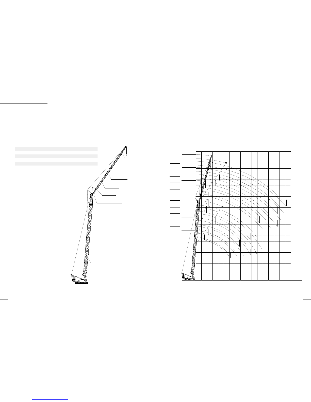
H operating condition
Boom length Insert
m 3 m 6 m 12m
20 1 - -
23 1 -
26 1 1 -
29 - - -1
32 1 - 1
35 - 1 1
38 1 1 1
41 - - 2
44 1 - 2
47 - 1 2
50 1 1 2
53 - - 3
56 1 - 3
59 - 1 3
62 1 1 3
65 - - 4
68 1 - 4
71 - 1 4
74 1 1 4
77 - - 5
80 1 - 5
83 - 1 5
86 1 1 5
Boom head(1m)
Transitional insert(6m)
12m boom insert(5 pieces)
6m boom insert(1 pieces)
3m boom insert(1 pieces)
Boom base(10m)
64
60
68
72
76
92
96
84
88
80
56
48
52
44
40
36
28
32
20
24
12
16
8
5
0
85°
30°
68
62
65
71
74
77
80
86
89
92
83
59
53
56
47
50
44
38
41
29
32
35
23
26
20
0 8 12 16 20 24 28 32 36 40 44 48 52 56 60 64 68
Working radius (m)
Lifting height(m)
H operating condition working radius diagram
H operating condition

SANY CRAWLER C RANE
SCC2600A
27
26
H OPERATIng CONDITION LOAD CHARTS H OPERATIng CONDITION LOAD CHARTS
Unit:(t)
SCC2600A Crawler Crane – H Operating Condition Load Charts
Boom length 2 0-86m Rear coun terweight 100t Car body counterwei ght 30t
Boom length (m)
Radius(m)
56 59 62 65 68 71 74 77 80 83 86
Boom length (m)
Radius(m)
8
8
9
114.0 114. 0 98.9 98.9
9
10
92.0 9 0.0 9 0.0 90.0 89.0 83.3 83.3 83.3
10
12
91.0 87. 2 85.6 76.3 72.8 67. 0 63.7 60.4 60.0 5 9.0 59.0
12
14 79.1 77.7 74 .9 73 .1
71.8 65 .1 60.3 5 4.9 51.8 51.2 50.0
14
16 68.1 6 7.0 65.6 64.4 63.0 62.0 54.8 52.1 48.2 47. 5 46.0 16
18 59.4 58.5 57. 3 56.2 55.1 54.2 53.0 47.4 4 5.5 44.9 39.0 18
20 52.4 51. 6 50.5 49.6 48.6 47. 8 46.8 45.9 42.9 39.4 35.9 20
22 46.6 45.9 44.9 44.1 43.2 42.5 41.5 40.8 39.8 36.6 3 2.1 22
24 41.8 41.1 40.2 39.5 38.6 38.0 37.1 36.4 35.6 35.0 31.1 24
26 37.6 37.1 36.2 35.6 34.7 34.2 33.4 32.7 31.9 31.4 28.7 26
28 33.7 33.6 32.8 32 .1 31.4 30.9 30.1 29.5 28.7 28.2 27.4 28
30 30.2 3 0.1 29.8 29.2 28.4 28.0 27. 2 26.6 25.9 25.4 24.7 30
32 27.2 27.1 26.8 26.5 25.8 25.4 24.7 24 .1 23.4 23.0 22.3 32
34 24.6 24.5 24.2 24.0 23.5 23.1 22.4 21.9 21.2 20.8 20.1 34
36 22.3 22.2 21.9 21.7 21.3 2 1.1 20.4 19.9 19.2 18.8 18.2 36
38
20.3
20.2 19.8 19.6 19.3 19.1 18. 6 18.1 17. 4 1 7.1 16.4 38
40
19.0
18.4 18.2 17.8 17.4 17.3 16.9 16.5 15.8 15.5 14.8 40
42
17.5
17.1 16.9 16.3 16.0 15.7 15. 3 15.0 14.3 14.0 13.4 42
44
16.2
15.9 15.5 14.9 14.7 14.5 13. 8 13.6 13.0 12.7 12 .1 44
46
15.0
14.5 14.0 13.7 13.4 13. 2 12.5 12.3 11.8 11.5 10.8 46
48
13.4
13.5 13 .1 12.6 12.5 12.3 11. 3 11.1 10.6 10.3 9.7 48
50
12.5
12.5 12.0 11. 7 11.5 11.2 10.2 9.9 9.6 9.3 8.7 50
52 11.5 11 .0 10.5 10.3 10.0 9.2 8.9 8.5 8.3 7.7 52
54 10.2 10.0 9.5 8.6 8.2 8.0 7.6 7.4 6.8 54
56 9.0 8.8 8.7 7.3 7.1 6.7 6.6 6.0 56
58 7.9 7.8 6.5 6.3 5.9 5.8 5.2 58
60 7.0 7.0 5.8 5.5 5.1 5.0 4.5 60
62 6.0 5.0 4.8 4.4 4.3 3.8 62
64 5.4 4.4 4.1 3.8 3.6 3 .1 64
66 3.7 3.5 3.1 3.0 2.5 66
68 2.9 2.5 2.4 68
SCC2600A Crawler Crane – H Operating Condition Load Charts
Boom length 2 0-86m Rear coun terweight 100t Car body counterwei ght 30t
Boom length (m)
Radius(m)
20 23 26 29 32 35 38 41 44 47 50 53
Boom length (m)
Radius(m)
5
260.0
5
6
238.4 224.9 223.6 204.2 194.0
6
7
207. 9 2 07.6 202.2 191.4 174 .4 1 69.1 165.0 158.0
7
8
183.8 178 .3 174. 4 170. 6 166.3 15 7.9 156.5 1 41.8 126 .3 125.0 12 4.0 122.0
8
9 15 6.1 153 .4 149.4 145 .4
142.7 142.7 141.3 130.2 122.1 11 7.6 115. 0 113 .0
9
10 141. 2 13 7.8 135.7 132 .2 13 0.1 129 .2 128.0 12 5.8 115 .5 11 5.5 10 7.1 104. 9 10
12 11 0.1 10 8.2 107.7 1 07.4 10 7.1 107.7 105.5 102.4 10 2.4 100.0 9 7.8 95.8 12
14 89.6 88.8 88 .1 8 7.7 87.2 87.2 8 6.9 86.8 85.8 84.2 82.4 80.9 14
16 74. 6 74. 2 73.8 73.5 72.8 72.6 73.8 72.3 72.3 72.3 70.8 69.5 16
18 63.8 63.3 62.8 62.5 62.5 62.6 62.0 62.3 61. 6 61.5 61.7 60.7 18
20 60.7 5 5.1 5 4.7 54.4 54.3 54.6 54.5 54.3 54.2 54 .1 53.8 53.5 20
22 49.5 48.8 48.3 48.2 48.2 48 .1 48.0 47. 8 47.7 4 7.5 47.6 22
24 43.8 43.5 43.1 43.0 42 .8 42.7 42.6 42.5 42.3 42 .7 24
26 39.1 39.0 39.1 38.9 38.9 38.0 38.3 38.2 38.1 26
28 37.0 35.0 35.1 34.9 3 4.8 3 4.5 34.5 34.2 34.0 28
30 31.4 31.6 31.4 31.3 31.1 31.0 30.7 30.5 30
32 28.6 28.4 28.3 28 .1 28.0 27. 7 2 7.5 32
34 25.8 25.7 25.5 25.4 25 .1 24.9 34
36 24.6 23.4 23.4 23.1 22.8 22 .7 36
38 22.3 21.7 22.0 20.8 20.6 38
40 20.0 20.2 19.5 19.2 40
42 17.8 17.7 17.6 42
44 16.9 16.8 16.5 44
46 16.5 15.2 46
Notes: 1. The actual we ight is a value that t he rated weight in t his table is subt racted by the weig hts of the hooks, ha ngers, and wir e ropes winding o n the hooks and on th e boom head.
2. The rated load in this table is measured under the condition that the heav y object is lifted slowly and stably from the level and hard soil grou nd.
Unit:(t)
SANY CRAWLER C RANE
SCC2600A
29
28
Fixed jib combination
Jib length
(m)
Insert
Boom length
(m)
Angle between boo m
and jib
6 m 11.5 m
13 - - 29~62 10°, 30°
19 1 - 29~62 10°, 30°
24.5 - 1 29~62 10°,30°
30.5 1 1 29~62 10°, 30°
36 - 2 29~62 10°, 30°
42 1 2 29~62 10°, 30°
Fixed jib working range dia gram
Jib tip(6.5m)
11.5m jib insert(2 pieces)
6m jib insert(1 pieces)
Jib base(6.5m)
Angle between boom and jib(10°,30°)
30°
Boom(29m-62m)
Fixed jib (jib angle: 10° +30°)
Lifting height(m)
Working radius (m)
80
75
85
90
95
115
105
110
100
70
60
65
55
50
45
35
40
25
30
15
10
20
5
5 1510 20 25 30 35 40 45 50 55 60 65 70 75 80 85 90
Boom (62m)
Jib (+42m)
Boom (62m)
Boom (62m)
Boom (62m)
Boom (62m)
Boom (62m)
Boom (62m)
Boom (62m)
Boom (62m)
Boom (62m)
Jib (+36m)
Jib (+30.5m)
Jib (+24.5m )
Jib (+19m )
Jib (+13m)
Jib (+36m)
Jib (+30.5m)
Jib (+24.5m )
Boom (62m)
Jib (+19m )
Boom (62m)
Jib (+42m)
Boom (29m)
Jib (+42m )
Boom (29m)
Jib (+36m)
Boom (29m)
Jib (+30.5m )
Boom (29m)
Jib (+24.5m)
Boom (29m)
Jib (+19m )
Boom (29m)
Jib (+13m )
Boom (29m)
Jib (+42m )
Boom (29m)
Jib (+36m)
Boom (29m)
Jib (+30.5m )
Boom (29m)
Jib (+24.5m)
Boom (29m)
Jib (+19m )
Boom (29m)
Jib (+13m )

SANY CRAWLER C RANE
SCC2600A
31
30
Unit:(t)
Fixed jib load CHARTS
SCC2600A Fixed Jib Load Charts (Without Jib Head Pulley Block)
Without mai n hook; jib angle: 10°
Boom length (m) 29 35 Boom length (m)
Jib length (m)
Radius(m)
13 19 24.5 30.5 36 42 13 19 24.5 30.5 36 42
Jib length (m)
Radius(m)
9
64.1 9
10
64.4 64.4
10
12
59.3 52. 9 62 .7 54. 2
12
14
53.1 4 9.7 44. 4 34.7 56.6 51.5 45.2
14
16 47.9 4 4.7 38.9 31.9
24.5 51.4 47.3 41 .6 32.8 24.1
16
18 4 3.7 40.6 3 4.1 28 .1 23.7 17.4 47.1 43.2 36.5 29.9 23.4 17.2 18
20 4 0.1 37. 2 30.4 25.0 2 1.8 16.8 42.5 39. 8 32.6 26.8 2 2.7 16.7 20
22 3 7.1 34.4 27. 5 22.7 19.7 16.2 38.0 3 6.9 29.8 24.2 20.9 16.1 22
24 3 4.1 31.8 24.9 20.5 17. 9 15.7 33.8 3 4.0 26.9 22 .1 19.0 15.6 24
26 30.5 29.3 22.9 18.8 16. 3 14. 4 34. 2 30.8 24.8 20.1 17.5 15. 2 26
28 29.2 26.9 20.9 17.3 1 5.1 13.2 30.6 27. 6 23.0 18.7 16.1 14.0 28
30 28.0 25.0 19 .4 16.0 13.9 12.2 29.3 25.0 21. 4 17.3 14.9 13 .0 30
32 26.9 23.0 18.1 14. 9 12 .8 11.3 26.6 22.7 19.9 16 .1 14.0 11. 9 32
34 24.5 22.5 17.0 13 .9 12.0 10.5 24.9 22.1 18 .6 15.1 12 .9 11.1 34
36 21.8 16 .7 13.1 11 .8 9.8 23.3 21.4 1 7.4 14.2 12.1 10.4 36
38 2 0.1 16.2 12.2 11 .6 9.7 21.3 19.6 16.4 13.3 11.4 9.8 38
40 18.5 15. 8 11.5 11.1 9.1 19.5 18 .1 15.5 12.6 10.7 9.2 40
42 15.0 11. 3 10.5 9.0 16.7 15.4 11. 9 10.5 9.0 42
44 14.3 10.7 9.9 8.5 15.4 14. 5 11.3 10.2 8.5 44
46 10.3 9.4 8.0 13.5 10.7 9.7 8.0 46
48 9.8 8.9 7.7 12.6 10.2 9.1 7.6 48
50 9.4 8.4 7.1 11.6 9.7 8.7 7.2 50
52 8.0 6.8 9. 3 8.4 6.8 52
54 6.8 6.5 8.9 7.9 6.5 54
56 6.1 7.5 6.2 56
58 5.9 7.2 5.9 58
60 5.5 7.0 5.6 60
62 5.4 62
64 5.1 64
Notes: 1. The actual we ight is a value that t he rated weight in t his table is subt racted by the weig hts of the hooks, ha ngers, and wir e ropes winding o n the hooks and on th e boom head.
2. The rated load in this table is measured under the condition that the heav y object is lifted slowly and stably from the level and hard soil grou nd.
Fixed jib load CHARTS
Unit:(t)
SCC2600A Fixed Jib Load Charts (Without Jib Head Pulley Block)
Without mai n hook; jib angle: 10°
Boom length (m) 41 47 Boom le ngth (m)
Jib length (m)
Radius(m)
13 19 24.5 30.5 36 42 13 19 24.5 30.5 36 42
Jib length (m)
Radius(m)
10
10
12
63.3 53.0 64.1
12
14
57.3 47.7 42.5 59.3 53.1
14
16
52.6 43.7 38.5 30.5 51.1 50.4 42.8 30.7
16
18 46.4 40.4 35.5 29.7
22.1 4 4.6 4 4.3 40.9 30.1 22.5
18
20 41.0 37.8 32.9 27.8 21.5 16.6 39.5 39.2 37.2 2 9.4 2 2.0 16.3 20
22 36.5 35.2 30.8 25.4 20.9 16.1 35.2 35.0 3 3.8 27.0 21.4 15.8 22
24 32.8 32.7 29.0 23.3 20.0 15. 6 33.6 31.5 31.0 24.7 20.9 15.5 24
26 29.6 29.6 26.4 21.5 18 .2 15 .1 32.2 28.5 28.5 22.8 19.4 15.0 26
28 30.2 26.9 24.5 20.0 17. 0 14 .7 31.0 25.9 26.0 21. 3 17. 9 14.6 28
30 2 7.1 24.5 22.9 18.4 15.7 14.2 2 8.1 23.6 23.7 19.9 16.8 14.3 30
32 27. 5 22.3 21. 4 17. 2 14.6 13.2 27. 0 21.6 21.8 18.5 15 .7 13.5 32
34 24.9 23.0 20.0 16 .1 13.8 12.4 24.4 21 .1 20.0 1 7.5 14.6 12.5 34
36 22.7 20.9 18. 8 15.2 12.9 11.5 22.2 20.5 18 .4 16.4 13.9 11.9 36
38 21.8 19 .2 17. 4 14.3 12.1 10.8 21.3 18.7 17.0 15.5 13.1 11.2 38
40 20 19 .0 16.0 13.6 11.5 10 .2 19.5 18.2 15.5 14.6 12. 4 10.5 40
42
18.3
17.7 15.7 12.9 10 .8 9.7 17.8 16.7 15.3 13 .9 11.7 9.9 42
44
16.8
16.3 14.5 12 .2 10.3 9.0 16.3 16.2 15.0 13.2 11.1 9.4 44
46 15.1 13.4 11. 6 9.8 8.7 15 15.6 13.8 12.5 10.5 8.9 46
48 14.9 12. 4 11.0 9. 3 8.2 13.7 14 .4 13.4 11.5 1 0.1 8.5 48
50 13.7 11 .4 10.6 8.8 7.7 13.2 12.4 10.6 9.6 8.0 50
52 10.6 1 0.1 8.5 7.3 12.2 11.4 9.8 9.2 7. 7 52
54 10.5 10.2 8.0 7.0 11.2 10 .5 9.7 8 .7 7.4 54
56 9.4 7.7 6.7 9.7 9.5 8.4 7.0 56
58 8.7 7.4 6.4 9.0 8.8 8.0 6.8 58
60 8.6 7.1 6.1 8.2 7. 4 6.4 60
62 6.8 5.9 7. 9 6.9 6.2 62
64 6.5 5.5 7.6 6.4 5.9 64
66 5.3 5.9 5.6 66
68 5.1 5.4 5.4 68
70 4.9 5.1 70
72 4.7 72
74 4.4 74
Notes: 1. The actual we ight is a value that t he rated weight in t his table is subt racted by the weig hts of the hooks, ha ngers, and wir e ropes winding o n the hooks and on th e boom head.
2. The rated load in this table is measured under the condition that the heav y object is lifted slowly and stably from the level and hard soil grou nd.

SANY CRAWLER C RANE
SCC2600A
33
32
Fixed jib load CHARTS
SCC2600A Fixed Jib Load Charts (Without Jib Head Pulley Block)
Without mai n hook; jib angle: 10°
Boom length (m) 53 56 Boom length (m)
Jib length (m)
Radius(m)
13 19 24.5 30.5 36 42 13 19 24.5 30.5 36 42
Jib length (m)
Radius(m)
10
10
12
58.8 58.8
12
14
56.9 52.7 55.7 49.5
14
16
49.1 48.5 39.8 48.2 47. 6 38.2
16
18 43.0 42.6 39.2 28.8
21.8 42 .1 41. 8 37. 7 2 8.1
18
20 38.0 37. 7 3 7.6 28.3 21. 4 16.0 3 7.2 37.0 3 6.8 27.6 22.4 16 .9 20
22 33.8 33.7 33.6 2 7.8 20.9 15 .6 35.3 33.0 32.9 27. 2 22.0 16.5 22
24 32.3 30.3 30.2 25.9 20.5 15.2 31.6 29.6 29.6 26.6 21.5 16.1 24
26 29 .1 2 7.3 27.4 24.1 20.0 14.9 30.2 26.7 26.8 24.5 21.0 15.8 26
28 28.3 24.8 24.9 22.4 18.8 14 .5 28.9 24.2 24.3 22.8 20.6 15.4 28
30 26.9 22.6 22.7 20.9 1 7.7 14 .2 27. 6 23.4 2 2.1 21. 5 19.2 15.0 30
32 27. 2 22.0 20.8 19. 6 16.5 13.8 26. 5 22.8 20.3 20.2 18.1 14. 6 32
34 24.8 21.3 19.1 18 .5 15.6 13. 3 24.1 22.7 18.5 18 .6 17. 0 14.3 34
36 22.7 20.7 17.5 17.3 14.6 12.5 22 22.4 17.0 17.1 15.9 13. 7 36
38 20.7 1 9.1 16.1 16. 2 13.9 11. 9 20.2 20.5 16. 6 15.7 15 .1 12. 9 38
40 18.9 18. 5 15.8 14.9 13.2 11.1 18.4 18. 8 16.3 14.5 14.4 12.2 40
42
17.2
17.9 15.5 13.8 12.5 10.6 16.9 17.3 15.0 13.4 13 .7 11.5 42
44
15.7
16.4 14.3 12 .8 11. 9 10 .1 15. 4 15.9 14.6 12.3 13.0 11.0 44
46
14.4
15 13.3 11.8 11.2 9.5 14 14.6 14. 0 11.4 12.2 10.5 46
48
13.1
13.8 12. 2 11.0 10.8 9.1 12. 7 13.4 13. 8 10.5 11. 4 9.9 48
50
12
12.6 11.1 10 .1 10.2 8.6 11. 6 12.2 12.7 10.3 10.5 9.4 50
52
10.9
11.5 10.9 10.0 9.5 8.2 10.5 11.2 11.7 1 0.1 9.7 9.0 52
54
9.9
10.6 10.0 9.8 8.8 7.9 9.6 10.2 10.7 9.4 9.0 8.6 54
56 9.7 9.4 9.3 8.2 7. 5 8.7 9.3 9.8 9.4 8.2 8.2 56
58 8.8 9.3 9.0 7. 5 7.2 8.4 9 9.3 7.6 7. 7 58
60 8.6 8.9 7.0 6.9 7.7 8.2 8.5 7.0 7.1 60
62 7.8 8.2 6.4 6.5 7. 5 7.8 6.4 6.5 62
64 7.1 7. 5 5.9 6 .0 6.8 7.1 5.9 6.0 64
66 6.8 5.4 5.6 6.1 6.5 5.4 5.4 66
68 6.2 5.0 5.1 5.9 4.9 5.0 68
70 4.5 4.7 5.3 4.5 4.6 70
72 4.1 4.2 4.0 4.1 72
74 3.7 3.8 3.6 3.7 74
76 3.5
3.2 3.3 76
78 3.2 3.0 78
80 2.6 80
Notes: 1. The actual we ight is a value that t he rated weight in t his table is subt racted by the weig hts of the hooks, ha ngers, and wir e ropes winding o n the hooks and on th e boom head.
2. The rated load in this table is measured under the condition that the heav y object is lifted slowly and stably from the level and hard soil grou nd.
Fixed jib load CHARTS
SCC2600A Fixed Jib Load Charts (Without Jib Head Pulley Block)
Without mai n hook; jib angle: 10°
Boom length (m) 59 62 B oom length (m)
Jib length (m)
Radius(m)
13 19 24.5 30.5 36 42 13 19 24.5 30.5 36 42
Jib length (m)
Radius(m)
10
10
12 12
14
54.7 46.5 53.6
14
16
47.3 46.0 36.5 46.4 43.5 35.0
16
18 41. 4 41.1 36 .1 27. 3
40.5 40.3 3 4.7 26.6
18
20 36.5 36.4 35.6 26.9 20.7 35.8 35.6 34.2 26.3 20.3 20
22 34.7 32.5 32.4 26.5 20.3 15.3 36.0 31. 8 31.7 25.8 20.0 15. 2 22
24 31.0 29.1 29.1 26.0 19.9 15.0 32.3 28.5 28.5 25.4 19.6 14.9 24
26 30.7 26.3 26.3 25.2 19.5 14. 6 30.7 25.7 25.8 25.0 19. 3 14.6 26
28 29.9 23.8 23.9 23.6 19.1 14.3 30.8 24.8 23.3 23.3 18.9 14.2 28
30 28.6 23.0 21.8 21.8 18.5 14.0 2 7.9 23.9 2 1.2 21.2 18 .5 14.0 30
32 26 22.9 19.9 19.9 17.3 13.8 25.3 23.8 19.4 19 .4 17.7 13.7 32
34 23.7 22.1 18.2 18.2 16. 3 13.4 23 23.3 17.7 17.8 16.7 13.4 34
36 21.6 2 1.9 16.7 16.7 15 .5 13 .1 20.9 21.3 17.3 16.3 15.8 13 .1 36
38 19.7 2 0.1 16. 3 15.4 14.6 12.4 19.1 19.4 16.8 14. 9 14.9 12. 7 38
40 18 18.4 15.9 14. 2 13.9 11.7 1 7.4 17.8 16 .3 13.7 13. 8 11.9 40
42
16.5
16.9 14.6 13.1 13.1 11 .2 15. 9 16.3 14.9 12 .6 12.8 11.4 42
44
15.1
15.5 13.4 12.0 12.2 10. 5 14.5 14.9 13.8 11.6 11.7 10.7 44
46
13.8
14.2 12.4 11.1 11.2 10. 0 13.2 13.6 12.9 11. 4 10.8 10. 3 46
48
12.6
13 11. 4 10.9 10 .4 9.5 12 12. 4 12.8 1 1.1 10.0 9.8 48
50
11.4
11.9 11.1 10 .6 9.5 9.2 10.9 11 .3 11.8 10.6 9.2 9.2 50
52
10.4
10.9 10.7 10.4 9.4 9.3 9.9 10.3 10.8 10 .1 8.4 8.5 52
54
9.4
10 10.4 9.9 8.6 8 .7 9 9. 4 9.8 10 .1 7.7 7.8 54
56
8.5
9.1 9.5 9.7 8.0 8.0 8.1 8.5 9 9.2 7.1 7.1 56
58
7.7
8.3 8.7 8.9 7.4 7.4 7.3 7.7 8.1 8.4 6.5 6.5 58
60 7.5 7.9 8.2 6.7 6.8 6.5 6.9 7.4 7.6 5.9 6.0 60
62 6.7 7. 2 7.4 6.2 6.2 6.2 6.7 6.9 5.4 5.5 62
64 6.1 6.5 6.8 5.6 5 .7 5. 5 6 6.2 4.9 5.0 64
66 5.9 6.1 5.1 5.2 4.9 5.3 5.6 4.4 4.5 66
68 5.3 5.5 4.6 4 .7 4.7 5 4.0 4.1 68
70 4.9 4. 2 4.2 4.2 4.4 3.5 3.6 70
72 4.4 3.8 3.8 3.9
3.2 3.2 72
74 3.9 3.4 3.4 3.4 2.8 2.9 74
76 3.0 3.0 2.9 2.4 2.5 76
78 2.6 2.6 2.0 2 .1 78
80 2.3 1.7 1.8 80
82 2.0 1. 5 82
84 1.7 1.2 84
Notes: 1. The actual we ight is a value that t he rated weight in t his table is subt racted by the weig hts of the hooks, ha ngers, and wir e ropes winding o n the hooks and on th e boom head.
2. The rated load in this table is measured under the condition that the heav y object is lifted slowly and stably from the level and hard soil grou nd.
Unit:(t)
Unit:(t)

SANY CRAWLER C RANE
SCC2600A
35
34
SCC2600A Fixed Jib Load Charts (Without Jib Head Pulley Block)
Without mai n hook; jib angle: 30°
Boom length (m) 29 35 Boom length (m)
Jib length (m)
Radius(m)
13 19 24.5 30.5 36 42 13 19 24.5 30.5 36 42
Jib length (m)
Radius(m)
12
12
14
27.8 28.4
14
16
26.2 26.9
16
18
24.7 20.6 25.5 21
18
20 23.4 19.4 1 7.5
24.3 19.9
20
22 22.3 18.4 16.5 23.2 19 16.8 22
24 21.3 17.5 15.7 13.9 22.3 18 .1 16 14 .1 24
26 20.5 16.7 14. 9 13.2 21.4 17.3 15.3 13.5 26
28 19.7 16 14.2 12 .6 11. 8 20.7 16.7 14.7 12.9 12 28
30 19 15.3 13.6 12 11 .2 20 16 14.1 12 .3 11. 5 30
32 18.4 14 .8 13 11.5 10.7 10 19. 4 15.5 13. 5 11.8 11 10.3 32
34 17. 9 14.3 12.5 11 10.3 9.5 18.8 14.9 13.1 11.4 10 .5 9.8 34
36 17. 5 13. 8 12.1 10.5 9.8 9.1 18.3 14.5 12.6 10.9 10.1 9.4 36
38 13.4 11 .7 10. 2 9.4 8.7 17. 9 14.1 12 .3 10.6 9.8 9 38
40 13 11. 3 9.8 9.1 8.4 17. 6 13 .7 11.9 10.2 9.4 8 .7 40
42 12.7 11 9.5 8.7 8.1 17.3 13.3 11. 5 9.9 9.1 8.4 42
44 10.7 9.2 8.4 7. 8 13 11.2 9. 6 8.8 8.1 44
46 10.5 8.9 8. 2 7. 5 12.8 10.9 9.3 8.5 7.8 46
48 10.2 8.6 7.9 7. 2 10.7 9 8.2 7.6 48
50 8.4 7.7 6.9 10.5 8.8 8 7.3 50
52 8.2 7.4 6.6 10.3 8.6 7.8 7 52
54 8 7.2 6.4 8.4 7.6 6.8 54
56 7.1 6.2 8.2 7.4 6.5 56
58 6.9 5.9 8.1 7.2 6.3 58
60 6.8 5.7 7.1 6 60
62 5.5 6.9 5.9 62
64 5.3 6.8 5.7 64
66 5.5 66
68 5.4 68
70 5.2 70
Fixed jib load CHARTS Fixed jib load CHARTS
SCC2600A Fixed Jib Load Charts (Without Boom Hook and Counterweight 100+30t)
Without mai n hook; jib angle: 30°
Boom length (m) 41 47 Boom le ngth (m)
Jib length (m)
Radius(m)
13 19 24.5 30.5 36 42 13 19 24.5 30.5 36 42
Jib length (m)
Radius(m)
14
14
16
26.9 2 7.9
16
18
25.7 20.9 26.7
18
20
24.6 19.9 25.6 20.7
20
22 23.6 19 16.7
24.7 19.8 17.4
22
24 22.7 18 .2 16 23.8 19.1 16.7 24
26 21.9 17.5 15.3 13.3 23 18.4 16 13.9 26
28 21 .1 16.9 14.7 12.8 11 .8 22.2 17. 7 15. 4 13.3 28
30 20.4 16.3 14. 2 12.3 11 .4 21.6 17.1 14.9 12.8 11.8 30
32 19.8 15 .7 13.7 11.8 10.9 10 20.9 16.6 14.4 12.4 11 .4 10. 4 32
34 19.3 15. 2 13.2 11 .4 10. 5 9.6 20.4 16.1 13 .9 12 11 10 34
36 18.8 14. 8 12.8 11 1 0.1 9.3 19.9 15 .6 13.5 11.6 10.6 9.7 36
38 18.3 14. 3 12.4 10. 5 9.8 8.9 19.4 15.2 13.1 11.2 10. 3 9.4 38
40 17. 9 14 12 .1 10 .1 9.4 8.6 18.9 14.8 12 .7 10.9 9.9 9 40
42 17. 6 13 .6 11. 7 9.6 9.1 8.3 18.5 14.4 12.4 10.6 9.6 8.7 42
44 17. 3 13. 3 11.4 9.2 8.8 8 16.9 14.1 12.1 10.3 9.3 8.5 44
46
15.8
13 11 .1 8.9 8.6 7. 8 15.5 13 .8 11. 8 10 9.1 8.2 46
48 12.8 10.9 8.5 8.3 7.5 14. 2 13.5 11. 5 9.7 8.8 8 48
50 12.5 10.6 8.3 8.1 7.3 12.9 13. 3 11.3 9.5 8.6 7.7 50
52 12.3 10.4 8 7.9 7.1 12.8 11.1 9.3 8.4 7. 5 52
54 10.2 7.8 7.7 6.9 11.7 10.8 9.1 8.2 7.3 54
56 10 .1 7.7 7.5 6.7 10.7 10.6 8.9 8 7.1 56
58 7.5 7.3 6.5 10. 5 8.7 7.8 6.9 58
60 7.4 7.1 6.3 9.8 8.5 7.6 6.8 60
62 7.3 7 6 .1 8.9 8.4 7. 5 6.5 62
64 6.9 5.9 8.2 7.3 6.3 64
66 6.7 5. 8 8.1 7.2 6. 2 66
68 6.6 5.6 7.4 7 6 68
70 5.4 6.9 5.8 70
72 5.3 6 .7 5 .7 72
74 5.2 5.5 74
76 5.3 76
78 5.3 78
Notes: 1. The actual we ight is a value that t he rated weight in t his table is subt racted by the weig hts of the hooks, ha ngers, and wir e ropes winding o n the hooks and on th e boom head.
2. The rated load in this table is measured under the condition that the heav y object is lifted slowly and stably from the level and hard soil grou nd.
unit:(t)
Unit:(t)
Unit:(t)

SANY CRAWLER C RANE
SCC2600A
37
36
SCC2600A Fixed Jib Load Charts (Without Boom Hook and Counterweight 100+30t)
Without mai n hook; jib angle: 30°
Boom length (m) 53 56 Boom length (m)
Jib length (m)
Radius(m)
13 19 24.5 30.5 36 42 13 19 24.5 30.5 36 42
Jib length (m)
Radius(m)
14
14
16
28.3 28.5
16
18
27.2 27.4
18
20
26.2 21 26.4 21.1
20
22 25.2 20.2
25.5 20.3
22
24 24.4 19.4 16.9 24.6 19.6 17 24
26 23.6 18.8 16.3 14 23.9 19 16.4 26
28 22.9 18.2 15. 7 13.5 23.2 18.3 15 .9 13.6 28
30 22.2 17. 6 15.2 13.1 12 22.5 1 7.8 15.4 13.2 1 2.1 30
32 21.6 17.1 14.7 12.6 11.6 21.9 17.3 14.9 12.7 11.7 32
34 21 16 .6 14.3 12. 2 11.2 10.2 21.4 16 .8 14.4 12. 3 11.3 10.2 34
36 20.5 16 .1 13.9 11.8 10.8 9.8 20.8 16. 3 14 12 10.9 9.9 36
38 20 15 .7 13.5 11.5 10.5 9.5 20.4 15.9 13.6 11.6 10.6 9.6 38
40 19.6 15. 3 13.1 11.2 10.2 9.2 19.5 15.5 13. 3 11.3 10.3 9.3 40
42 18 14.9 12. 8 10.9 9.9 8.9 17.7 15 .2 12.9 11 10 9 42
44 16.4 14.6 12.4 10.6 9.6 8.7 16.1 14.8 12.6 10.7 9.7 8 .7 44
46
15
14.3 12. 2 10.3 9.3 8.4 14.7 14.5 12.3 10. 4 9.4 8.5 46
48
13.7
14 11. 9 10 9.1 8.2 13.4 14.2 12.1 10 .2 9.2 8.3 48
50
12.5
13.5 11 .7 9.8 8.9 7.9 12.2 13.2 11. 9 9.9 9 8 50
52
11.4
12.3 11 .4 9.6 8.6 7.7 1 1.1 12 11. 6 9.7 8.8 7.8 52
54
10.3
11.3 11.2 9.4 8.4 7.5 10 11 11. 4 9.5 8.5 7. 6 54
56 10.3 11 9.2 8.2 7.3 9.1 10 10.8 9.3 8.4 7.4 56
58 9.4 10.2 9 8 7. 2 8.1 9.1 9.9 9 .1 8.2 7.3 58
60 8.5 9.3 8.8 7. 9 7 8.2 9 8.9 8 7.1 60
62 8.5 8.6 7.7 6.8 7.4 8.2 8.8 7.8 6.9 62
64 7.7 8.4 7.6 6.6 6.6 7.4 8 .1 7.7 6. 8 64
66 7 7.7 7.4 6.4 6.7 7. 4 7.5 6.6 66
68 7 7.3 6.2 6 6.7 7.3 6.3 68
70 6.3 6.9 6 6 6.6 6.2 70
72 5.7 6.3 5.9 5.4 6 6 72
74 5.7 5.8 4.8 5.4 5.8 74
76 5.1 5.6 4.8 5.3 76
78 4.5 5 4.3 4.7 78
80 4.5 3 .7 4.2 80
82 4 3.7 82
84 3.5 3. 2 84
86 2.7 86
Fixed jib load CHARTS
Notes: 1. The actual we ight is a value that t he rated weight in t his table is subt racted by the weig hts of the hooks, ha ngers, and wir e ropes winding o n the hooks and on th e boom head.
2. The rated load in this table is measured under the condition that the heav y object is lifted slowly and stably from the level and hard soil grou nd.
SCC2600A Fixed Jib Load Charts (Without Boom Hook and Counterweight 100+30t)
Without mai n hook; jib angle: 30°
Boom length (m) 59 62 Boom length (m)
Jib length (m)
Radius(m)
13 19 24.5 30.5 36 42 13 19 24.5 30.5 36 42
Jib length (m)
Radius(m)
16
16
18
27.6 27.7
18
20
26.6 21.2 26.8
20
22
25.7 20.5 25.9 20.6
22
24 24.9 19.8 17.1
25.1 19.9 17. 2
24
26 24 .1 1 9.1 16. 5 24.4 19.3 16.7 26
28 23.5 18.5 16 13.7 23.7 18.7 16.1 13 .8 28
30 22.8 18 15 .5 13.3 12.1 23.1 18.2 15 .6 13.4 30
32 22.2 17. 5 15 12.8 11.7 22.5 17. 7 15. 2 12.9 11. 8 32
34 21.6 17 14.6 12.5 11. 4 10.3 2 1.9 17. 2 14.7 12.6 11. 4 10.3 34
36 21 .1 16.5 14 .2 12 .1 11 10 21.4 16.7 14. 3 12.2 11.1 10 36
38 20.6 16 .1 13.8 11.7 10.7 9.7 20.3 16. 3 14 11.9 10 .8 9.7 38
40 19 .1 15.7 13.5 11.4 10.4 9.4 18.5 15.9 13 .6 11. 5 10.5 9.4 40
42 17. 5 15 .4 13 .1 11 .1 1 0.1 9.1 16.9 15.6 13 .3 11. 2 10.2 9.2 42
44 16 15 12.8 10.8 9.8 8.8 15.4 15.2 13 11 9.9 8.9 44
46 14.6 14.7 12.5 10.6 9.6 8.6 14.1 14.9 12.7 10.7 9.7 8 .7 46
48
13.3
14.2 12. 3 10.3 9.3 8.4 12.8 13.7 12.4 10 .4 9.4 8.4 48
50
12.1
13 12 10.1 9.1 8 .1 11.6 12.5 12.2 10.2 9.2 8.2 50
52
10.9
11.9 11.8 9.9 8.9 7.9 10.6 11.4 12 10 9 8 52
54
9.9
10.8 11. 6 9.6 8.7 7.7 9.9 10.4 11.1 9.8 8.8 7. 8 54
56
9
9.9 10.7 9.4 8.5 7.5 8.6 9.4 10.2 9.6 8.6 7. 6 56
58
8.1
9 9.8 9.3 8.3 7.4 7. 7 8.5 9. 3 9.4 8.4 7.5 58
60
7.2
8.1 8.9 9.1 8 .1 7.2 6.9 7.7 8.4 9 8.2 7.3 60
62 7.3 8.1 8 .7 8 7 6.1 6.9 7.6 8.2 8.1 7.1 62
64 6.5 7.3 7.9 7.8 6.8 6.1 6.9 7. 5 7.9 6.9 64
66 5.8 6.6 7.2 7. 6 6.6 5.4 6.2 6.7 7.3 6.8 66
68 5.9 6.5 7 6.5 4.7 5.5 6.1 6.6 6.6 68
70 5.3 5.8 6.4 6.3 4.8 5.4 6 6.4 70
72 5.2 5.8 6.2 4.2 4.8 5.3 5.8 72
74 4.6 5.2 5 .6 3.6 4.2 4.7 5.2 74
76 4 4.6 5 3.6 4.2 4.6 76
78 4 4.5 3.1 3.6 4.1 78
80 3.5 3.9 3.1 3.5 80
82 3 3.4 2.6 3 82
84 2.9 2 .1 2.5 84
86 2.5 2.1 86
88 2 1.6
88
Fixed jib load CHARTS
Notes: 1. The actual we ight is a value that t he rated weight in t his table is subt racted by the weig hts of the hooks, ha ngers, and wir e ropes winding o n the hooks and on th e boom head.
2. The rated load in this table is measured under the condition that the heav y object is lifted slowly and stably from the level and hard soil grou nd.
Unit:(t)
Unit:(t)

SANY CRAWLER C RANE
SCC2600A
39
38
Jib length
(m)
Insert
Boom length
(m)
Angle between boo m and jib
3m 6m 12m
21 1 1 - 26~62 65°~88°
24 - 2 - 26~62 65°~88°
27 1 1 -- 26~62 65°~88°
30 -- 1 1 26 ~62 65°~88°
33 1 1 1 26~62 65°~88°
36 - 2 1 26~ 62 65°~88°
39 1 2 1 26~62 65°~88°
42 -- 2 2 26~62 65°~88°
45 1 1 2 26~62 65°~88°
48 -- 2 2 26 ~62 65°~88°
51 1 2 2 26~ 62 65°~88°
54 -- 1 3 26~ 62 65°~88°
57 1 1 3 26~62 65°~88°
60 2 3 26~ 62 65°~88°
63 1 2 3 26~62 65°~88°
Luffing jib combination Luffing jib opera ting condition
w ork ing r a nge di agram
Jib top(6m)
Jib 12m section(3pieces)
Jib 6m section(2pieces)
Jib 3m section(1pieces)
Boom section(6m)
Boom section(26m-62m)
Lifting height(m)
Working radius (m)
Boom angle: 88′
63m
60m
57m
54m
51m
48m
45m
42m
39m
36m
33m
30m
27m
24m
21m
0 10 15 20 25 30 35 40 45 50 55 60 65 70 75 80 85 90 95 100
75°
62m
15°
15°
26m
63m
60m
57m
54m
51m
48m
45m
42m
39m
36m
33m
30m
27m
24m
21m
0
5
10
15
20
25
30
35
40
45
50
55
60
65
70
75
80
85
90
95
100
105
110
115
120
125
130
135

SANY CRAWLER C RANE
SCC2600A
41
40
Luffing jib load CHARTS
SCC2600A Luffing Jib Load Charts (Without Jib Head Pulley Block)
Boom length (m) 26 Boom length (m)
Jib length (m) 21 24 27 30 J ib length (m)
Boom a ngle (°)
Radius(m)
88 85 80 75 70 65 88 85 80 75 70 65 88 85 80 75 70 65 88 85 80 75 70 65
Boom angle(°)
Radius(m)
10
90 89.1 10
12
88 89.8 84. 8 83.8 78.9
12
14
77 84.3 73. 9 82.6 73. 5 81.1 73.4
14
16
67
72.4 71. 9 64.6 71.4 64.3 70.9 63.6 69.8
16
18
59
62.9 63.8 56.9
62.7 62 .7 56.6 62 .4 61.6 56.7 62 .2
18
20
50
54.7 5 7.4 55.4 51. 2 55.2 56.4 50.9 55.4 55.3 50.5 55. 2 54.0 20
22
38
45.5 51. 7 5 0.1 4 4.8 49.6 51 .2 49.4 45.9 4 9.7 50.2 46.1 49.4 49.0 22
24 3 4.2 46.3 44. 9 43.5 3 7.0 43.1 46.2 4 4.7 41. 3 45.3 45.9 43.9 42 .0 45.2 44. 9 43.0 24
26 41. 9 40.6 39.3 35.4 41.9 40.5 39.2 34.7 40.8 41.7 39.8 38.3 41.1 41.1 39.5 26
28 37.0 35.9 34.7 38 .1 36 .9 35.7 27.7 33.8 37.9 36.3 35.1 32 .1 3 7.6 37. 5 3 6.1 28
30 32.9 31.9 35. 0 33.9 32.8 31.7 26. 4 34.9 33.3 32.2 26.4 32 .3 34.4 3 3.1 31.8 30
32 2 9.4 31.2 30.2 29. 2 32.1 30.7 29.7 28.9 25.9 31.7 30.5 29 .3 32
34 28.0 2 7.1 28.4 2 7.5 26.9 29. 4 28.3 27.1 26.4 34
36 25.1 25.6 24.9 26.3 25.2 24.6 36
38 23. 3 24.5 23.6 22. 9 38
40 22.0 21. 4 40
42 20.1 42
44 44
46 46
48 48
50 50
52 52
54 54
56 56
58 58
60 60
62 62
Luffing jib load CHARTS
SCC2600A Luffing Jib Load Charts (Without Jib Head Pulley Block)
Boom length (m) 26 Boom length (m)
Jib length (m) 33 36 39 42 Jib leng th (m)
Boom a ngle (°)
Radius(m)
88 85 80 75 70 65 88 85 80 75 70 65 88 85 80 75 70 65 88 85 80 75 70 65
Boom angle(°)
Radius(m)
10
10
12 12
14
72.7 70. 2 62.6
14
16
63.2
68.6 62. 9 61.9 54.1
16
18
55.8
61.1 55.8
60.1 55.4 59.1 53.5
18
20
50.3
55.0 50. 0 54.1 49.4 53.3 48.3 52.4 20
22
45.5
49.2 48.6 45.4 4 9.1 47. 4 4 4.7 48.4 43.7 4 7.7 22
24
41.7
44.5 44.5 41.4 44.3 4 3.4 40.7 44.3 42.7 39.9 4 3.7 41 .1 24
26
38.4
40.8 41. 0 38. 3 37. 9 40.6 39.9 3 7.5 40.7 3 9.3 36.5 40.1 37. 9 26
28
33.3
37.6 3 7.7 35.2 3 5.1 37.4 3 7.0 34.8 34.8 37.3 36.3 3 4.2 34.0 37.0 35 .1 28
30
28.3
33.1 34.6 32 .3 31.1 30.8 34.5 34.0 32.1 32 .1 34. 3 33.9 31.8 31.5 34.2 32.7 31.1 30
32
23.6
28.2 31. 9 29.8 2 8.7 26.8 30. 9 31.4 29.6 28.5 28 .7 32.0 31. 2 29.3 2 9.3 32.0 30 .4 28.9 32
34
18.9
23.3 29.6 2 7.5 26.6 22. 3 26.6 2 9.1 27.5 26.4 25 .0 29.0 28. 9 27. 2 2 6.1 26.6 29 .7 28 .1 26.8 34
36 26.0 25.7 24.8 2 4.3 18.4 22.0 2 7.0 25.5 24.6 2 1.9 25.2 26.9 25.3 24 .3 23.2 27. 2 26.1 24.8 23.9 36
38 20.6 23.9 23.0 22.7 1 7.9 25.2 23.8 22. 9 22.0 1 7.5 20.9 25.0 23.6 22.6 21.7 20.3 23.8 24.4 23.1 22.3 38
40 22.3 21.6 21. 3 23.6 22.2 21.4 20 .6 14.2 17.3 23.4 2 2.1 21.2 20 .3 16.3 2 1.0 22.8 21.7 20. 8 19.9 40
42 20. 3 19.9 2 0.9 20 .1 19. 3 22.0 2 0.7 19.9 19.1 13.6 16.7 21. 4 20.3 19.5 18.7 42
44 18 .7 18.9 18.1 20.6 19.4 18. 6 17. 9 13 .5 18 .1 19.1 18.3 17.5 44
46 17.7 17.1 18.3 17. 6 16. 8 14.9 18.0 1 7.3 16.6 46
48 16.1 16.6 15.8 17.0 16. 3 15.6 48
50 15.0 15.4 14 .7 50
52 13.9 52
54 13.2 54
56 56
58 58
60 60
62 62
64 64
66 66
68 68
Notes: 1. The actual we ight is a value that t he rated weight in t his table is subt racted by the weig hts of the hooks, ha ngers, and wir e ropes winding o n the hooks and on th e boom head.
2. The rated load in this table is measured under the condi tion that the heavy object is lifted slowl y and stably from the level and hard soil ground.
Unit:(t)
Unit:(t)

SANY CRAWLER C RANE
SCC2600A
43
42
Luffing jib load CHARTS
SCC2600A Luffing Jib Load Charts (Without Jib Head Pulley Block)
Boom length (m) 26 Boom length (m)
Jib length (m) 45 48 51 54 Jib l ength (m)
Boom a ngle (°)
Radius(m)
88 85 80 75 70 65 88 85 80 75 70 65 88 85 80 75 70 65 88 85 80 75 70 65
Boom angle(°)
Radius(m)
10
10
12 12
14 14
16
48.2
16
18
47.7
42.8
38.4 31.9
18
20
47.1
46.7 42.1 41.9 3 7.9 31.5 20
22
43.7
45.9 41 .6 41.3 37. 4 3 7.2 3 1.1 3 0.9 22
24
39.9
42.1 39.4 4 0.8 36.8 3 6.6 30.6 3 0.4 24
26
36.6
38.8 3 7.3 3 6.1 3 8.2 36.0 36.1 30.2 30.1 26
28
33.6
35.9 34.5 33.5 35 .4 33.9 33 .2 34.8 33. 4 29.8 29. 6 28
30
31.3
33.4 32.0 31 .1 32. 9 31.6 30.9 32. 4 31.1 29. 3 29.3 28.5 30
32
29.1
31.1 30.0 28 .7 28.8 30 .7 29.4 2 8.7 30.2 2 9.0 28.4 2 9.0 28.2 32
34
27.2
28.9 2 7.9 26.8 27.1 28.7 27.6 26.5 26.9 28.3 27.1 25.9 26.4 2 7.9 26.7 34
36
24.7
26.9 25.9 24.9 25.4 2 6.8 25.7 24.7 25.2 26.6 25.5 24. 4 23.7 26.2 25.1 24.0 36
38
22.0
25.1 24.2 23.2 23.0 23.4 24.9 24.0 23.0 22 .1 23.7 24.8 23.8 22.8 21. 4 24.3 23.6 2 2.6 38
40 19.4 22 .1 22.6 21.7 21.5 20.6 23.3 22.4 21.5 20.6 21. 9 23.1 22.2 21.2 20. 3 19.3 21. 8 2 2.1 21.2 40
42
15.6
19.6 21. 2 20.3 2 0.2 18.6 18.5 21. 0 21.0 20.2 19.3 19.4 21.7 20. 8 19.9 19.1 17. 4 19.6 20.7 19.8 18. 9 42
44
13.0
15.4 19 .9 19 .1 18 .9 17. 6 16.4 18.6 19.7 18 .9 18 .1 17.3 17. 5 19.9 19.5 18.7 17.8 15.7 17. 6 19 .4 18.5 17.7 44
46
10.4
12.8 17.4 18.0 17.8 16.5 12.2 14.7 18. 6 17. 8 17.0 16.3 15.6 17.7 18.4 17.6 16.8 16.0 1 4.1 15.9 18. 3 17. 5 16.7 46
48 14.3 16.9 16 .7 15.6 10.0 12. 2 17. 6 16 .8 16.0 15.3 11 .5 15.7 17.4 16.6 15 .8 15 .1 12.6 14. 3 17. 2 16.5 15.7 14.9 48
50 16.0 15.8 14 .7 9.7 16.6 15 .8 15 .1 14.5 9.5 11.5 16.4 15.7 14 .9 14.2 11.3 13. 0 15.8 15.5 14. 8 14.0 50
52 15.1 15.0 13 .9 15.7 15.0 14.3 13. 7 9.5 13.1 14.8 14.1 13. 4 7.3 11 .5 14.2 14. 7 14.0 13.3 52
54 14 .1 13.1 14. 2 13.6 13.0 10.7 14. 0 13.3 12.7 5 .3 7. 4 12. 8 13.9 13.2 12.5 54
56 12 .4 12. 9 12.2 13. 2 12.6 12.0 5.5 8.5 13.1 12.5 11. 9 56
58 11.6 12. 5 12.0 11.3 6. 8 9.6 11.9 11. 3 58
60 11.3 10.8 7.9 11. 3 10.6 60
62
10.3 10 .6 10 .1 62
64 9.5 64
66 66
68 68
Luffing jib load CHARTS
SCC2600A Luffing Jib Load Charts (Without Jib Head Pulley Block)
Boom length (m) 26 Boom length (m
Jib length (m) 57 60 63 Ji b length (m
Boom a ngle (°)
Radius(m)
88 85 80 75 70 65 88 85 80 75 70 65 88 85 80 75 70 65
Boom angle(°)
Radius(m
10
10
12 12
14 14
16 16
18 18
20
31.0 28.2
20
22
30.5 27.7 25. 3
22
24
30.1 29.9 27. 3 2 7.2 24.9
24
26
29.5 29.4 26.9 26 .7 24.6 24.5
26
28
29.1 29.0 26.6 26.5 24 .1 24.0
28
30
28.8 28.5 28.0 26.1 26.0 23.8 23.7
30
32
28.3 28.3 27.7 25.7 25.7 25.2 23.3 23.3
32
34
26.6 2 7.5 26.3 2 5.3 25.2 24.8 23.0 23.0 2 2.6
34
36
24.9 25.7 24.7 24.6 24.8 24. 2 2 2.6 22.6 22. 2
36
38
23.3 24.2 23.1 2 2.1 23.0 23.9 22.8 21.7 22.2 22.2 21.9
38
40
21.9 22. 9 21.9 20 .8 21.8 2 2.5 21.4 20.4 21.6 21.9 21.0 20.0
40
42
20.5
21.4 20. 4 19.5 20. 5 21.2 20 .3 19.3 20 .3 20.8 19.8 18.9
42
44
19.4
20.1 19.2 18 .4 17. 5 19.4 19. 9 19.0 18.1 19.3 19.7 18.7 17. 8
44
46
17.5
18.9 1 8.1 17.2 16.4 18.3 18.7 17.8 17.0 16.2 18 .1 18. 5 17. 6 16. 8
46
48
15.8
17.8 17. 0 16 .2 15.4 16.6 17.6 16.8 16.0 15 .2 17.3 17.5 16.6 15.8 14.9
48
50
14.2
16.0 16.0 15.3 14.6 13.9 14. 9 16.7 15 .8 15 .1 14 .3 15.6 16.5 15.7 14.9 14.1
50
52
10.2
14.5 15.1 14.4 13.8 13.1 13.4 15. 2 14.9 14.2 13.5 12.8 14.1 15.5 14.8 14.0 13 .3
52
54
8.5
10.2 14. 3 13.7 13.0 12.3 12.1 13. 8 14 .1 13. 5 12.8 12.1 12.9 14. 5 14.0 13.2 12.5 11.9
54
56
6.8
8.6 13.6 13.0 12. 2 11.6 7.7 9.4 13. 4 12.8 12.1 11.4 11.5 13.1 13.2 12.5 11.9 11.2
56
58
6.8 12.9 12.2 11. 6 11.0 6.3 7.9 12.7 12.1 11.4 10.8 7.2 11.8 12.5 11.9 11.2 10.5
58
60
12.2 11.6 11.0 10.4 4.9 6.4 8.8 11.4 10.8 10.3 5. 9 7.3 11.9 11. 3 10. 6 10.0
60
62
11.6 11.0 10.4 9.9 7. 5 10.9 10.3 9.7 4.5 5 .9 7.7 10.6 10. 0 9.5
62
64
10.4 9.9 9.4 5 .8 10.3 9.7 9.2 4.5 6 .9 10.1 9.5 8.9
64
66 9.4 8.9 9.7 9.2 8.7 5.4 9.5 9.0 8.5 66
68 8.4 8.7 8.3 9.1 8.6 8.0 68
70 7.8 8.6 8.1 7. 6 70
72 7.7 7. 2 72
74 6.8 74
Notes: 1. The actual we ight is a value that t he rated weight in t his table is subt racted by the weig hts of the hooks, ha ngers, and wir e ropes winding o n the hooks and on th e boom head.
2. The rated load in this table is measured under the condi tion that the heavy object is lifted slowl y and stably from the level and hard soil ground.
Unit:(t)
Unit:(t)

SANY CRAWLER C RANE
SCC2600A
45
44
Luffing jib load CHARTS
SCC2600A Luffing Jib Load Charts (Without Jib Head Pulley Block)
Boom length (m) 38 Boom length (m)
Jib length (m) 21 24 27 30
Boom a ngle (°)
Radius(m)
88 85 80 75 70 65 88 85 80 75 70 65 88 85 80 75 70 65 88 85 80 75 70 65
Boom angle(°)
Radius(m)
10
89.8 10
12
87.4 83. 0 82.6 75.6
12
14
78.2 75.7 76.8 74.3 75.3 74.1
14
16
68.9
66.6
67.7
65.4 66 .4 64.3 65. 4 63.3
16
18
61.6
59.5 56.3 60.5
58.5 59. 4 57. 4 5 8.5 56.6
18
20
52.8
53.6 50.8 54.6 52 .7 49.9 5 3.6 51.8 52.9 51.1 20
22
37.4
49.0 46.2 49.9 4 8.1 45.5 49.0 47. 3 44.6 48.2 4 6.6 44.0 22
24 4 5.0 42.3 40. 0 45.8 44.2 41.7 39.3 44.9 43.4 40.9 44.3 42.8 40.3 24
26 41.4 39.2 36.9 40.1 40.9 3 8.4 36.3 41.6 40.1 3 7.7 35.6 41. 0 39.5 37.2 26
28 36.0 3 4.2 32.2 37. 8 35.7 33.6 3 7.8 37. 3 35. 0 32.9 3 8.1 36.7 34.6 32.5 28
30 31.4 29.7 32.9 31. 2 29.5 34 .6 32.7 3 0.7 35.6 34. 3 32.2 30.2 30
32 28.9 27. 5 25.9 30.3
28.8
27.3 30. 2 28.6 2 7.0 30.6 31. 9 30.2 2 8.3 32
34 25.4 24.0 26.6 25.2 23.8 28.0 26.5 25.0 2 9.4 28.0 26. 4 24.8 34
36 22 .3 23.5 2 2.1 24.7 23.2 21.9 26.0 24.6 23.1 36
38 20. 8 21.9 20.6 23.0 21.7 20.3 24.2 23.0 21.6 20.3 38
40 19.3 20. 3 19.1 2 1.4 20.2 18.9 40
42 17. 8 18.9 17.7 42
44 16.7 17.7 16.7 44
46 15.7 46
48 48
50 50
52 52
54 54
56 56
58 58
60 60
62 62
64 64
66 66
68 68
Luffing jib load CHARTS
SCC2600A Luffing Jib Load Charts (Without Jib Head Pulley Block)
Boom length (m) 38 Boom length (m)
Jib length (m) 33 36 39 42 Jib leng th (m)
Boom a ngle (°)
Radius(m)
88 85 80 75 70 65 88 85 80 75 70 65 88 85 80 75 70 65 88 85 80 75 70 65
Boom angle(°)
Radius(m)
10
10
12 12
14
66.8
59.6
14
16
64.3 59 .1
52.9 47.6
16
18
57.5
55.5 56 .6
54.7 52 .5 47. 2
18
20
52.0
50.2 51 .2 49.4 50.3 48 .6 46.7 4 6.5 20
22
47.4
45.8 46 .7 45 .1 45 .9 44.3 45. 3 43.7 22
24
43.6
42.0 39.6 42.8 41.4 3 9.0 42.2 40.7 41. 6 4 0.1 24
26
40.2
38.8 36.5 39.6 38 .2 35.9 3 9.0 37. 5 3 5.3 38.4 37.1 34.8 26
28
37.4 36.0
33.8
36.8
35.5 33.3 36.2 3 4.8 32.7 35.6 34.4 32.2 28
30
34.9 33.6 31.6
29.6
34.3 33.0
31.1 29.2
33.8
32.5 30.4 33.3 32 .0 30 .1 30
32
31.7 31.5 29.5
27.7
32.1 31.0
29.0
27.2 31.6 30. 3
28.4 26.6 31.1 30.0 28.1 32
34
29.3 27. 7 26.0
24.4
29.3 29 .1 27. 3
25.6
29.6 28.5
26.7 25.0
29.3
28.1 26.4 2 4.7 34
36
27.3 25.8 24.3
22.9
22.1 27.2 25.7 24.0
22.4
27.8 26.8 25.1
23.5
27.5 26.5
24.8 23.1 36
38
24.0 22.7 21.3 25 .3 23.9 22. 5
21.1
25.1 25.1 23.7
22.1 20.6
25.9 25.0
23.3 21.8 38
40
22.5 21.2 19.9
18.6
23.7 22 .4 21.1 19.7 22.2 23.5 22.1 20.8
19.4
23.8 23.5 2 2.1
20.6 19.2 40
42
19.9 18.6 17. 5 21.0 19.7 18.5 17. 3 2 2.1 20.8 19.5 18. 2 21.3 22.0 20.7 19. 4
18.1 42
44
18.6 17. 6 16.4 18.5 17. 4 16.2 19. 5 18.3 17.1
15.9
18.6 20.7 19.4 18. 2
17.0 44
46
16.5 15.5 17.5 16.4 15.2 18. 4 17.3 16.1 14.9 1 9.1 18.3 17.1 15.9
14.9 46
48
14.6 15.4 14.4 16.3 15. 2 14.1 17.3 16 .2 15.0 14.0
48
50
13.7 14. 5 13.6 14.3 13.3 15.3 14 .2 13.1
50
52
12.8 13. 5 12.6 14. 4 13.4 12.4
52
54
11.9 12.7 11. 8
54
56
11.3 12.0 11. 2
56
58
10.5
58
60 60
62 62
64 64
66 66
68 68
Notes: 1. The actual we ight is a value that t he rated weight in t his table is subt racted by the weig hts of the hooks, ha ngers, and wir e ropes winding o n the hooks and on th e boom head.
2. The rated load in this table is measured under the condi tion that the heavy object is lifted slowl y and stably from the level and hard soil ground.
Unit:(t)
Unit:(t)

SANY CRAWLER C RANE
SCC2600A
47
46
Luffing jib load CHARTS
SCC2600A Luffing Jib Load Charts (Without Jib Head Pulley Block)
Boom length (m) 38 Boom length (m)
Jib length (m) 45 48 51 54 Jib l ength (m)
Boom a ngle (°)
Radius(m)
88 85 80 75 70 65 88 85 80 75 70 65 88 85 80 75 70 65 88 85 80 75 70 65
Boom angle(°)
Radius(m)
10
10
12 12
14 14
16
42.9
16
18
42.5
38.3
34.7
18
20
42.0
38.0 34 .4 28.7 20
22
41.6
41.4 37. 5 37.4 34.0 3 3.8 28.4 22
24
41.0
39.4 3 7.2 36.9 3 3.6 33.4 28.1 27. 9 24
26
37.8
36.5 3 6.7 35.8 3 3.2 33.0 27.7 2 7.6 26
28
35.1 33.8
31.7
34.6
33.3 32. 8 32.6 27.5 2 7.3 28
30
32.7 31.5 29.5 3 2.2 31.0
29.0
31.7
30.4 28.4 27. 3 27.1 30
32
30.6 29.4 27. 5 30. 2 29 .0
27.1
29.6 28.4
26.6 26. 9 26.8 25.9 32
34
28.7 27. 6 25.8 24 .1 28.3 2 7.2 25 .4 27. 8 26.6
24.8
26.6
26.3 24.5 34
36
27.0 26.0 24.3 22.6 26.6 25.6 23.9 22.2 2 6.1 2 5.1 23.4 25.7 24.8
23.0 36
38
25.6 24.5 22.9 21.3 25.1 24 .1 22.5 20.9 24.7 23.7 22.0
20.4
24.3 23.3
21.7 38
40
24.0 23.2 21.6 20 .1 23.8 22.8 21.2 19.7 23. 3 22. 3 20 .8 19.3 23.0 22.0 20.4
18.9 40
42
22.4
21.8 20.4 19.0 1 7.6 2 2.4 21.6 20 .1 18.6 2 2.1 21. 2 19.6 18.2 2 1.7 20.8 19.4 17. 9
42
44
20.3
20.5 19.3 17. 9 16.7 21.1 20. 3 19.0 17.6 16.3 20.9 2 0.1 18.6 17.2 15.8 20.5 19.7 18. 3 16.9
44
46
18.0
19.4 18 .1 16.9 15.7 19 .2 19.2 17. 9 16.7 15.5 19.7 19.0 17. 6 16.3 15. 0 18 .5 18.7 17. 4 16.0 14. 8
46
48 18. 2
17.1 15 .9 14.8 13.7 17.2 18.1 16.9 15.8 14.6 18.1 17.9 16.7 15.5 14. 2 16 .6 17.7 16.5 15.2 14.0
48
50 16 .1
15.0 14.0 12. 9
15.1
17.1 15 .9 14.9 13.8 12 .7 16.4 16.9 15.8 14. 6 13.5 14.7 16.7 15.7 14.4 13. 2
50
52 15. 2
14.2 13 .1 12.2
15.6
15.1 14.0 13.0 12. 0
14.6
16.0 14.9 13.8 12.7 11.7 13.1 15.6 14.8 13 .7 12.6
52
54 13.4
12.5 11. 5
14.3
13.3 12.2 11.3
15.0
14.1 13.1 12.1 11.0 13.8 14.0 12 .9 11.9 10.9
54
56 11. 8
10.9
12.6
11.6 10 .7
13.3
12.3 11. 3 10.4 13. 2 12.2 11. 3 10.3
56
58 11. 2 10.3 11 .9 11.0
10.1
12.6
11.7 10. 8 9 .8 12.5 11.6 10.6 9.7
58
60 9.7 10.4 9.5 11.1
10.2 9.3
11.9
11.0 10.1 9.2
60
62 9.2 9 .1 9.6
8.8
10.4
9.5 8.6
62
64 8.6 9 .2 8.4 9.9 9.0
8.2
64
66 7.9 8.6 7.7 66
68
7.4
68
70 6.9 70
Unit:(t)
Luffing jib load CHARTS
SCC2600A Luffing Jib Load Charts (Without Jib Head Pulley Block)
Boom length (m) 38 Boom length (m)
Jib length (m) 57 60 63 Jib length (m)
Boom a ngle (°)
Radius(m)
88 85 80 75 70 65 88 85 80 75 70 65 88 85 80 75 70 65
Boom angle (°)
Radius(m)
18
18
20
28.4
26.0
20
22
28.1
25.7 23.6
22
24
27.7
27.5 25.4 23.2
24
26
27.4
27.2 25.0
24.9 22.9 22.8
26
28
27.1
26.8 24.7 24.6 22.6 22.5 28
30
26.7
26.6 24.4 24.2 22.2 22.1 30
32
26.4
26.3 25.5 24.0 23.9 22.0 21.9 32
34 26.1 25. 8 24.0 23.7 23.6 23.0 21.6 21.5 34
36 25.3 24 .3 22. 6 23.4 23.3 22 .1 21.3 21.2 20.7 36
38 23.9 22.9 21.2 23.1 22.4 20.8 21.0 20.9 20 .3 38
40 22.5 21.6 20.0 18. 5 2 2.1 21.2 19.6 20.7 2 0.6 19. 2 40
42 21.3 20.4 18.9 17.5 21.0 20. 0 18. 5 17.1 20.4 19.6 18.1 42
44 20.3 19 .4 17.9 16.5 19.8 19.0 17. 6 16.1 19.4 18. 5 17.1 15.7 44
46 19.2 18.4 16.9 15 .6 18. 8 18. 0 16 .6 15. 2 18.5 1 7.6 16.2 14.9 46
48 18.3 17.5 16.1 14.8 13.6 17.9 17.1 15. 8 14 .4 1 7.6 16.7 15.3 14.0 48
50
17.3
16.6 15.3 14.0 12.9 17. 0 16.3 14.9 13.7 12.5 16 .7 15. 8 14 .6 13.3 50
52
16.1
15.7 14.6 13.3 12.2 16.2 15. 5 14. 2 13.1 11. 9 15.8 15 .1 13.9 12.6 11. 4 52
54
14.8
14.9 13.8 12.7 11.6 15.2 14.7 13.5 12.3 11. 3 15 .1 14.4 13.1 12.0 10.9 54
56
13.4
14.0 13.1 12.0 11.0 10.0 14.0 13.9 12.9 11. 8 10.7 9.6 14. 2 13.7 12.5 11.4 10.3 56
58
12.0
13.3 12.3 11.3 10.4 9.5 12.7 13.1 12.2 11. 2 10.2 9. 2 13 .1 13.0 12.0 10.8 9.8 8.7 58
60 12. 3 11.7 10.7 9.8 8.9 11.4 12. 5 11.5 10.5 9.6 8.6 12.1 12 .3 11.3 10.4 9.3 8.3 60
62 11.1 10.2 9 .3 8.4 11. 8 10.9 10.0 9 .1 8.2 10 .9 11.7 10.7 9.8 8.8 7.8 62
64 10.5 9.6 8.8 7.9 10.4 9.5 8.6 7.7 9.7 11.1 10.2 9.3 8.4 7.5 64
66 9.2 8.4 7.5 9. 8 9.0 8 .1 7.3 10.0 9.6 8.7 7.9 7.0 66
68 7.9 7.1 8.6 7.7 6.9 9. 2 8.3 7. 5 6.7 68
70 7.5 6.8 8 .1 7.3 6. 5 7. 8 7.0 6. 3 70
72 6.3 6.9 6 .1 7.5 6.7 5.9 72
74 5.8 6. 3 5.6 74
76 5.5 5.2 76
78 5 .0 78
Unit:(t)
Notes: 1. The actual we ight is a value that t he rated weight in t his table is subt racted by the weig hts of the hooks, ha ngers, and wir e ropes winding o n the hooks and on th e boom head.
2. The rated load in this table is measured under the condi tion that the heavy object is lifted slowl y and stably from the level and hard soil ground.

SANY CRAWLER C RANE
SCC2600A
49
48
Luffing jib load CHARTS
SCC2600A Luffing Jib Load Charts (Without Jib Head Pulley Block)
Boom length (m) 50 Boom length (m)
Jib length (m) 21 24 27 30 J ib length (m)
Boom a ngle (°)
Radius(m)
88 85 80 75 70 65 88 85 80 75 70 65 88 85 80 75 70 65 88 85 80 75 70 65
Boom angle(°)
Radius(m)
10
10
12
72.0 71.5 65.3
12
14
72.6 69.3 69.3 63.8 58.6
14
16
64.4 61.4 63 .3 6 0.3 62 .1 59.2 5 7.4
16
18 57. 8 55.0
56.8
54.1
55.8
53.1 55.0 52.4
18
20 52.4 49.9 45.9
51.5
49.0
50.6
48.2
49.9
47.4 20
22 48.0
45.5
41.9
47.1 44.7
41.1
46.3 44.0 45.6
43.4 22
24 44.4
41.9
38.4
43.4 41. 2
37.8
42.6 40.4
37.1
42.0 39.9
36.6 24
26
38.9
35.6 32.6
40.3 38.2
34.9
39.5 3 7.4
34.3
38.9 36.9
33.8 26
28
33.0
30.2
35.6
32.5 29.7
36.8 34.8
31.9
36.2 34.4
31.4 28
30 3 0.9 2 8.2
30.3
27.7 33.3
32.6 29.7
27.1
33.9 3 2.1
29.3 26.7 30
32 26 .4 24.0
28.4
25.9 30.6
27.8
25.3
31.9 30. 2 27. 5
24.9 32
34 24.8 22. 6 26.8 24.3 22 .1
26.2
23.8
28.4 25.8
23.4 34
36 21.2 23.0 20.8 24.8 22.4 20.3
24.3
22.1 36
38 20.0 20.2 21.7 19.6
21.2
19.1
23.0
20.8 18.8 38
40 18.9 18.5 18.6 20.0 18.0 21. 8
19.7
17.7 40
42 17.7 17. 4 17. 5 17.1 17. 0 18. 7 16.8 42
44 16.5 16.1 16.1 17. 6 15.9 15. 8 44
46 15.4 15. 2 15.0 15.0 46
48 14.3 14.1 14.2 48
50 13.4 50
52 12.6 52
54 54
56 56
58 58
60 60
62 62
64 64
66 66
68 68
Unit:(t)
Luffing jib load CHARTS
SCC2600A Luffing Jib Load Charts (Without Jib Head Pulley Block)
Boom length (m) 50 Boom length (m)
Jib length (m) 33 36 39 42 Jib leng th (m)
Boom a ngle (°)
Radius(m)
88 85 80 75 70 65 88 85 80 75 70 65 88 85 80 75 70 65 88 85 80 75 70 65
Boom angle(°)
Radius(m)
10
10
12 12
14
53.6 48.9
14
16
52.7 48.2 44 .1 40.3
16
18 51.8 51.4
47.5
43.6
39.9
18
20 49.1 46.6
46.8
45.9
42.9
43.6
39.4
20
22 44.8
42.6 4 4.1 41.9 42.4 41.2 39.0
39.3 22
24 41.2
39.2 40. 6 38.5 40. 0 37. 9 3 8.5 37. 4
24
26 38.2
36.3
33.1
37.6 35.6
32.6
37.0 35.0 36.5 34.6
26
28 35.6 33.7
30.8
35.0
33.1
30.2
34.4 32.6
29.7
33.9 3 2.1
29.3 28
30 33.2 31.5 28.7 3 2.7 31.0
28.2
32.1
30.4 2 7.6 31.7 30.0
27.3 30
32 31.1 29.5 26.8 24.4 30.6 29.0
26.4
30.1 28.4
25.8 2 9.7 28 .1 25. 5
32
34 29.3 27.7 25.2 22.9 28.8 2 7.3 24.8 22.4 2 8.3 26.7
24.2
27.9
26.4 23.9
34
36 24.9 26.2 23.8 21.5 27. 3 25.7 23.3 21 .1 26.7 25. 2 22 .9 20.6 26.3 24.8
22.5
20.3 36
38 24.8 22.4 20.3 18.3 24. 2 24 .3 22.1 19.9 25.3 23.9 21.5
19.4
24.8 23.5
21.2
19.1 38
40 21.2 19.2 1 7.3 23.0 20.9 18. 8 16.8 23.2 22.6 20.3 18.3 23.6 22.2 20 .1
18.0
40
42 20.3 18.2 16.3 19.8 17. 8 15.9 2 1.4 19.3 17. 3 15.5 22.1 21.1 19.0 17. 0 42
44 1 7.3 15 .5 18.8 16.8 15 .0 20.4 18.4 16.4 14. 6 19.5 20 .1 18.0 1 6.1 14.3 44
46 16. 4 14.7 14.5 16 .0 14.3 1 7.5 15 .6 13.9 1 9.1 17.1 15 .3 13.6 46
48 14.0 13 .7 15.3 13 .6 13.3 16. 6 14.9 13.1 16.3 14. 6 12.9 48
50 13.1 13.0 14.4 13.0 12.7 1 4.1 12.5 12.2 15.6 13 .9 12.2 11. 9 50
52 12.3 12.2 12 .0 13.4 11.9 11.6 13.2 11 .6 11 .3 52
54 11.6 11.5 11.4 11.3 11.0 12.6 11.1 10.7 54
56 10.8 10 .7 10.4 10.5 10.2 56
58 10.2 9.9 10.0 9.7 58
60 9.3 9.5 9.2 60
62 8.7 62
64 8.2 64
66 66
68 68
Unit:(t)
Notes: 1. The actual we ight is a value that t he rated weight in t his table is subt racted by the weig hts of the hooks, ha ngers, and wir e ropes winding o n the hooks and on th e boom head.
2. The rated load in this table is measured under the condi tion that the heavy object is lifted slowl y and stably from the level and hard soil ground.

SANY CRAWLER C RANE
SCC2600A
51
50
Luffing jib load CHARTS
SCC2600A Luffing Jib Load Charts (Without Jib Head Pulley Block)
Boom length (m) 50 Boom length (m)
Jib length (m) 45 48 51 54 Jib l ength (m)
Boom a ngle (°)
Radius(m)
88 85 80 75 70 65 88 85 80 75 70 65 88 85 80 75 70 65 88 85 80 75 70 65
Boom angle (°)
Radius(m)
10
10
12 12
14 14
16 16
18
36.5
33.3
30.5
18
20
36.0
32.9 30. 2 25.7 20
22
35.6
35.8 32 .7 29.9 25.5 22
24
35.3
35.6 32. 3 32.4 29. 6 29.5 25. 2 25 .1 24
26
34.9
33.9 32. 0 32.0 29. 3 29.3 24. 9 24.8 26
28
33.3
31.5 31.6 31.1 2 9.1 2 9.0 24.7 24.6 28
30
31.1
29.4 26.6 30.6 28 .9 28.8 28 .4 24.4 24. 4 30
32
29.2
27.5 24.9 28.7 27.1 24.5 28.2 26.6 23.9 24 .1 24.1 32
34
27.4
25.8 23.4 2 6.9 25.4 23.0 26.5 24.9 22.4 23.9 23.9 22.1 34
36
25.8
24.3 22.0 25.4 23.9 21.6 24. 9 23.4 21 .1 23.7 23.1 20.8 36
38
24.4
23.0 20.7 18 .5 23.9 22.6 20.3 23.5 2 2.1 19.9 23.1 21.8 19.5 38
40
23.1
21.8 19 .6 17. 6 22.7 21. 3 19.2 17.1 22. 2 20.9 18.7 17. 2 21. 9 20.6 18.5 40
42
22.0
20.6 18.5 16.6 2 1.5 20.3 18.2 16.2 21.1 19.8 17.7 16. 3 20.8 19. 4 17. 4 15 .4 42
44
20.9
19.6 17.6 15.7 20.4 19. 2 17. 2 15 .3 20.0 18.8 16.7 15.3 19.7 18. 5 16.5 14 .6 44
46
18.7
18.6 16 .7 14.9 13.1 19.4 18.3 16.3 14.5 19.1 17. 8 15.9 14 .5 18.7 17.6 15. 6 13.8 46
48 17.8 15.9 14.1 12.4 17. 9 17.4 15.6 13.8 12.1 18.2 17.0 1 5.1 13.8 11.6 17. 8 16 .7 14.9 13.1 48
50 16. 9 15 .1 13. 4 11. 8 15. 8 16.7 14.8 1 3.1 11.4 17. 0 16 .2 14.4 13.1 11. 0 17.0 15.9 14 .1 12. 4 10.7 50
52 14.5 12.8 11.2 10.8 15.9 14.1 12.4 10.9 15.3 15.5 13.7 12. 5 10.4 15 .2 1 5.1 13.4 11 .8 10.2 52
54 13.8 12.2 10.6 10.2 13.5 11.9 10.4 9.8 14. 8 13 .1 11.8 9.9 14.5 12.8 11.2 9.6 54
56 11. 6 10.2 9.7 12.9 11. 3 9.8 9.3 1 4.1 12.5 11.3 9.4 8 .9 13.9 12.2 10.6 9.2 56
58 11.1 9.6 9.2 10. 8 9.4 8 .9 12.0 10.7 8. 9 8.4 13 .2 11 .6 10.2 8.6 8.1 58
60 9.2 8.8 10.3 8.9 8. 4 11. 3 10. 2 8.5 8. 0 11. 2 9.6 8.3 7. 7 60
62 8.7 8. 3 8.5 8.0 9.8 8.1 7.5 10.7 9.2 7.8 7.3 62
64 7.9 8.1 7.6 9.3 7. 7 7.1 8.8 7.5 6.9 64
66 7.5 7.2 7.3 6.8 8.4 7.1 6.5
66
68 6.8 7.0 6.4 6.8 6.2 68
70 6.5 6 .1 6.4 5.8 70
72 5.8 5.5 72
74 5.2 74
Unit:(t)
Luffing jib load CHARTS
SCC2600A Luffing Jib Load Charts (Without Jib Head Pulley Block)
Boom length (m) 50 Boom length (m)
Jib length (m) 57 60 63 Jib length (m)
Boom a ngle (°)
Radius(m)
88 85 80 75 70 65 88 85 80 75 70 65 88 85 80 75 70 65
Boom angle (°)
Radius(m)
20
25.6
20
22
25.3
23.2 21.4
22
24
25.0
23.0 21.2
24
26
24.8
24.7 22.7
22.7
20.9
26
28
24.5
24.4 22.4
22.4 20.6 20.5
28
30
24.2
24.1 22.2 22.1 20.3 20.3 30
32
23.9
23.9 22.0 21.9 20.2 20.1 32
34
23.7
23.6 21. 6 21. 7 21.6 19.9 19.8 34
36
23.4
22.7 20.3 21. 4 2 1.3 19.9 19.6 19. 5 36
38
22.8
21.3 19.1 21. 2 21.0 18.7 19.4 19.4 18.3 38
40
21.5
20.2 18.0 2 1.0 19.8 17.6 19.2 19 .1 17.2 40
42
20.3
19.1 1 7.0 20.0 18.7 16.6 19. 0 18. 3 16. 2 42
44
19.3
18.1 16.0 1 4.1 18.9 17. 7 15.7 13.8 18.5 17.3 15.3 44
46
18.4
17.1 15. 2 13. 3 18.0 16.7 14.9 13. 0 1 7.6 16.4 14.4 12.6 46
48
17.5
16.3 14.4 12.6 17.1 15.9 14.0 12.3 16 .7 15 .6 13.7 11.9 48
50
16.7
15.5 13.7 12.0 16.3 15.1 13.3 11.6 15.9 14. 8 13 .0 11.3 50
52
15.8
14.8 13.1 11.3 9.7 15.5 14.4 12.7 11. 0 15.1 14. 0 12 .3 10.6 52
54
15.1
14.1 12. 4 10. 8 9.3 14.9 13.8 12 .1 10.4 8. 9 14.4 13.4 11.7 10.1 54
56
14.0
13.5 11.8 10.3 8.7 8.1 13.1 11.5 9.9 8.4 13.8 12.8 11. 2 9 .5 8.0 56
58
12.5
12.9 11.3 9 .7 8.3 7.5 12.5 11. 0 9.5 7.9 7.0 12.2 10.6 9.0 7.6 58
60 12. 3 10. 8 9.3 7. 8 7.2 6. 8 12.0 10.4 8.9 7.6 6.3 11 .6 10.1 8 .6 7.1 60
62 10.3 8.8 7.5 6 .8 11.5 10.0 8.6 7.1 6.5 5.8 11. 2 9.6 8.1 6.8 62
64 9.8 8.5 7.1 6. 4 11.0 9.5 8.1 6.8 6 .1 5.3 10 .6 9.2 7. 7 6.4 5.7 64
66 9.5 8.0 6.8 6.1 9.1 7. 7 6.4 5.7 10.2 8.7 7. 4 6.0 5.3 66
68 7.7 6. 4 5.7 8 .7 7. 4 6.0 5.4 8.4 7.0 5 .7 5.0 68
70 7.3 6.0 5 .4 7. 0 5.8 5.1 8. 0 6.7 5.4 4.7 70
72 5.8 5.1 6.7 5.5 4.8 6.3 5.0 4.4 72
74 5.5 4.8 5.1 4.5 6.0 4.8 4 .1 74
76 4.5 4.9 4.2 5.8 4.5 3 .8 76
78 4.3 3.9 4.3 3.5 78
80
3.7 4.1
3.3 80
82 3.1 82
84 2.8 84
Unit:(t)
Notes: 1. The actual we ight is a value that t he rated weight in t his table is subt racted by the weig hts of the hooks, ha ngers, and wir e ropes winding o n the hooks and on th e boom head.
2. The rated load in this table is measured under the condi tion that the heavy object is lifted slowl y and stably from the level and hard soil ground.

SANY CRAWLER C RANE
SCC2600A
53
52
Luffing jib load CHARTS
SCC2600A Luffing Jib Load Charts (Without Jib Head Pulley Block)
Boom length (m) 62 Boom length (m)
Jib length (m) 21 24 27 30 J ib length (m)
Boom a ngle (°)
Radius(m)
88 85 80 75 70 65 88 85 80 75 70 65 88 85 80 75 70 65 88 85 80 75 70 65
Boom angle (°)
Radius(m)
10
10
12
57.7 53.9
12
14
55.2 51.8 48 .6 45.5
14
16
52.7
56.3
49.8
53.4 46. 9 44 .1
16
18 50.3
50.6 47.7
49.8 45. 2 48.6
42.7
45.4
18
20 48.2
46.0 45 .7 45.2 43 .5 44.4 41.3 43.7 20
22 45.2
42.1 37. 4 43.9
41.4
41.8 40.7 39. 9 40 .1 22
24 41.9
38.9 34.5 41.0 38.2 3 3.8 40.2 37.4 38.4 37. 0 24
26
36.1 32.0 38 .1 35.4 31.3 37. 4 34 .7 30.7 3 6.8 34.3 30. 2 26
28
33.8
29.7
33.0
29.2
34.8 32.3 28.5 34. 3 31.9 28 .2 28
30
27.7 2 7.1 31.0
27.3
32.7 30. 2 26.6 3 2.1 29.9 26.3 30
32
26.0 25.3 25.6 24.8 28.4 24.9 24.2 30 .2 28.0
24.6
32
34 23.8
24.0
23.3
23.5 22.7 26.4 23.1 22. 3 34
36 22. 4
17.5 22.7
21.9
22.1 21.3 25.0 21.8 21. 0 36
38
21.2 16 .5
20.7
16.0 20.1 20.6 19.8 38
40 15.5
19.6
15.1
19.0 14 .7 19.5
18.7
40
42 14.7
13.8
14.3
18.0 13 .9 18. 5 17. 7 13 .6 42
44
13.1
13.6
12.7 17.1 1 3.1 16.8 12.9 44
46 12.4 12.9 12. 0 12.4
11.5 16.0
12.2
46
48 11.7 11 .4
11.8 10.9
11.5
10.6 48
50 10.8
10.3 11.0 10.0 50
52 9.8
10.4
9.5
52
54 9.3 9 .0
54
56 8.6
56
58
58
60
60
62
62
64
64
66
66
68
68
Luffing jib load CHARTS
SCC2600A Luffing Jib Load Charts (Without Jib Head Pulley Block)
Boom length (m) 62 Boom length (m)
Jib length (m) 33 36 39 42 Jib leng th (m)
Boom a ngle (°)
Radius(m)
88 85 80 75 70 65 88 85 80 75 70 65 88 85 80 75 70 65 88 85 80 75 70 65
Boom angle (°)
Radius(m)
10
10
12
12
14
42.3
14
16
41.2 38.7
36.0 33 .4
16
18 40 .1
37.8
35.3
32.9
18
20 39.0
41.4 36.9 38. 5 34.6 32 .3 20
22 37.9
39.3 36. 0
37.9
33.8 35.2 31.8 32.7 22
24 36.7
36.3 35 .0 35.6 3 3.1 34.7 31.1 32.2 24
26 35.7
33.6 34 .0 33.0 32. 3 32.4 30. 5 31.8 26
28 33.7
31.3
27.5 33.0
30.8
27.0
31.5 30. 2 29.9 29. 8 28
30 31.5 29.3
25.7
31.0
28.7
25.2
30.4 28.2 24.7 29. 3 27. 8 30
32 29.6 27. 5
24.0
29.1 26.9
23.6
28.5
26.5 23.0 28 .2 26.0
22.7
32
34 27.9 25.8 22.6 2 7.4 25.4
22.1
26.9 24.8
21.6
26.5
24.5 21. 3 34
36 26.2 24.4 21.2 20.4 25.9 23.9
20.9
20.0 25.4 23.4
20.3
25.0
23.0 20 .1 36
38 23.1 20.1
19.2
24.6 22.7 19.7 18.8 24.0 2 2.1 19.2
18.2
23.7 21.8
18.9 38
40 19.0 18.2 2 1.5 18.6
17.7
22.8 21.0 18.2
17.2
22.4 20.6
17.8
16.9
40
42 18.1 17.2 20.4 1 7.6 16. 8 20.9 19.9 17. 2
16.2
18.4 19.6
16.9 15. 9 42
44 17.2 16.3 12.3 16.7 15.9 12.0 19.0 16 .3
15.4
16.7 18.6 16.0
15.1 44
46 15. 5 11.7 15.9 1 5.1 11 .3 15 .5 14.6 10.9 17.7 15. 2
14.3 46
48 14 .7 11.1 14.3 10.7 14.8 13.8
10.3
17.0 14.5 13.5 10. 0
48
50 14. 0 10.5 9.5 13. 6 10.2 14 .1 13.2 9 .7 13.8 12. 9
9.5 50
52 10.0 9.0 13.0 9.6 8.6 12 .5 9.3 13. 2 12.2
9.0 52
54 9.5 8.5 9.2 8.2 11 .9 8.7 7. 7 11.7 8 .6
54
56 8 .1 8.7 7. 7 11.4 8.3 7. 2 11.1 8.1 7.0
56
58 7. 7 8. 3 7.3 7.9 6.8 10.6 7.7 6.6
58
60 7. 3 6.9 7.6 6.5 7.3 6.2
60
62 6.6 6.1 6.9 5.9
62
64 5.8 6.6 5.5
64
66 5.5 5 .2
66
68 4.9
68
Notes: 1. The actual we ight is a value that t he rated weight in t his table is subt racted by the weig hts of the hooks, ha ngers, and wir e ropes winding o n the hooks and on th e boom head.
2. The rated load in this table is measured under the condi tion that the heavy object is lifted slowl y and stably from the level and hard soil ground.
Unit:(t)
Unit:(t)

SANY CRAWLER C RANE
SCC2600A
55
54
Luffing jib load CHARTS
SCC2600A Luffing Jib Load Charts (Without Jib Head Pulley Block)
Boom length (m) 62 Boom length (m)
Jib length (m) 45 48 51 54 Jib l ength (m)
Boom a ngle (°)
Radius(m)
88 85 80 75 70 65 88 85 80 75 70 65 88 85 80 75 70 65 88 85 80 75 70 65
Boom angle (°)
Radius(m)
18
30.5 28 .4 18
20
30.1
28.0 26 .0 22.4
20
22
29.6
27.6 25 .7 22 .1
22
24
29.2
29.9
27.2
27.7 25.3 21.9
24
26 28.6
29.5 26. 8
27.4 25.0 25.4
21.6
21.8
26
28 28.2
29.2 26. 4 27.1 24.7 2 5.1 21.4 21.6 28
30 27.6
27.3 26.0
26.8
24.3 24.8 21.2 21.3 30
32 27.1
25.6 2 2.1 25.6 2 5.1 24.0 24 .6 20.9 2 1.2 32
34 26.0
24.0 20.8 25 .1 23.6 20 .3 23.7 23.0 19. 9 20.6 21.0 34
36 24.5
22.6
19.5 2 4.1
22.1
19.1
23.3 21.7 18.6 2 0.3 20.7 18 .4 36
38 23.1 21. 3
18.5
22.8
21.0
18.0
22.3 20.5 17.6 20. 2 20.2 1 7.2 38
40 22.0 20.2
17.4
21.5 19.8
17.0
21.2
19.4 16. 6 19.9 19.1
16.2
40
42 20.9 19.2 16.5 15.4 20.4 18 .7
16.1
15.0 20.0 18.4
15.7
19.6
18.0 15 .3 42
44 16.5 18.2 15.6 14.6 19.4 17. 8
15.2
14.2 19.0 17.4
14.8 13.7
18.7
17.1 14.5 44
46 15.1 17.3 14.8
13.8
14.8 16.9 14.4 13 .4 18 .1 16.6 14.0
12.9
17.8 16.2
13.8 12.6 46
48 16.5 14.0 1 3.1 13.5 16.1 13.7
12.7
13.1 15 .8 13.3
12.2
16.6 15.4
13.1
11.9
48
50 15.8 13.4 12.4 9.0 12.3 15 .4 13.1 12.0 12. 0 14.9 12.6
11.5
15.5 14.7
12.3 11.3 50
52 12.8 11. 8 8.6 14.7 12. 4 11.4 8.2 11.1 14. 3 12.0
10.9 7. 7
14.4 14.0 11 .8
10.7 52
54 12 .2 11.2 8.1 14.1 11.9 10. 8 7.7 13 .7 11.4 10.4 7.3 9.9 13. 4 11.2
10.1
7.1
54
56 11.7 10.7 7.7 11. 3 10.3 7. 3 13 .1 10.9 9.8
6.9
9.0 12.8 10.6 9. 6 6.7
56
58 10. 2 7.3 6 .1 9. 8 6 .9 10.4 9.4 6.6 12.2 10.2 9 .1 6.3 58
60 9 .7 6.9 5. 8 9.3 6.6 5.4 9.9 8.9 6.2 9.7 8.6 5.9 60
62 6.6 5.4 8.9 6.2 5.0 9.5 8.5 5.9 4. 6 9.3 8.2 5.6 62
64 6.2 5.1 8.5 5.9 4.7 8.0 5.5 4.3 8 .8 7.8 5.3 4.0 64
66 5.9 4.8 5.6 4.4 7.7 5.2
4.0
7.4
5.0 3.7 66
68 4.5 5.3 4.1 5.0 3.7 7. 0
4.7
3.5
68
70 4. 2 5.0 3.9 4.6 3.5 6.7 4.4 3.2
70
72 4.0 3.6 4.4 3.2 4.1 3.0
72
74 3.4 3.0 3.9 2.7
74
76 2.7 2.5
76
78 2.3
78
80 2.1
80
Luffing jib load CHARTS
SCC2600A Luffing Jib Load Charts (Without Jib Head Pulley Block)
Boom length (m) 62 Boom length (m)
Jib length (m) 57 60 63 Jib length (m)
Boom a ngle (°)
Radius(m)
88 85 80 75 70 65 88 85 80 75 70 65 88 85 80 75 70 65
Boom angle (°)
Radius(m)
20
22.4
20
22
22.1
20.5 19.1
22
24
21.9
20.3 18.8
24
26
21.6
21.7 2 0.1 18.6
26
28
21.3
21.5 19.8
19.9 18.4 18.4
28
30
21.1
21.2 19.6 19.7 18.2 18. 2 30
32
20.9
21.1 19.4 19.4 18.0 18.0 32
34
20.6
20.9 19.2 19.3 17.7 17.8 34
36
20.3
20.6 17.8 18. 9 1 9.1 17.6 17. 6 36
38
20.2
19.7 16.7 18. 7 18. 9 16 .4 1 7.4 17. 5 38
40
19.9
18.6 15.8 18.5 18 .3 15.4 1 7.2 1 7.3 14.9 40
42
19.3
17.6 14.9 18. 4 17.3 14.5 17. 0 16.8 14.1 42
44
18.3
16.7 14.0 17.9 16.3 13.7 16.8 15.9 13.3 44
46
17.4
15.8 13.3 12.1 17.0 15 .5 13.0 16 .7 15.1 12.5 46
48
16.6
15.0 12.6 11.4 16.2 14.7 12 .2 11.0 15.8 14.3 11. 9 48
50
15.7
14.3 12.0 10.8 15 .4 14.0 11.6 10.4 15.0 13.6 11. 3 9.9 50
52
14.6
13.6 11.3 10.2 14.5 13.3 11.0 9.8 14.3 12.9 10.6 9.4 52
54
9.4
13.0
10.8 9.7
13.5
12.7 10.4 9.3 13 .4 12.3 10.1 8.8 54
56
8.6
12.4
10.3 9.1 6.3
8.2
12.1 9.9 8.8
12.7
11.7 9.5 8.3 56
58
7.9
11.9
9.8 8.7 5.9
7.5 11.5
9.5 8.3 5 .6
11.8
11.2 9.1 7. 9 58
60
11.3 9.3
8.2 5.5
6.8 11. 0 9. 0
7.8 5.2
6.3 10.6
8.6 7.4 4.8 60
62
10.9 8.9
7.8 5.2
10.5 8.6
7.4 4.9
5.9 10.2
8.2 7.0 4. 5 62
64
8.5 7. 4
4.9
10.1 8.2
7.0 4.6
5.3 9.7
7.8 6.6 4 .1 64
66
8.1 7.0
4.6 3.3
7.7
6.6 4.2
9.3 7. 4
6.2 3.9 66
68 7.7
6.6
4.3 3.0
7.4 6.3
4.0 2.7
8.9 7. 0
5.9 3.6 2. 2 68
70
6.3 4.1
2.8 7.1
5.9
3.7 2.4
6.8 5.5
3.3 2.0 70
72 6.0
3.8
2.5
5.6
3.5 2.2
5.2
3.1 1.8 72
74
3.5
2.3 5.3
3.2
2.0
4.9
2.9 1.5 74
76 3.3
2.1
5.0
3.0
1.7
4.6 2.6
1.3 76
78 3.1
1.9
2.8
1.5
4.4
2.4
1.1 78
80
1.7 2.6
1.3 2.3 80
82
1.5 1.1 2.1
82
84
1.8
84
Unit:(t)
Notes: 1. The actual we ight is a value that t he rated weight in t his table is subt racted by the weig hts of the hooks, ha ngers, and wir e ropes winding o n the hooks and on th e boom head.
2. The rated load in this table is measured under the condi tion that the heavy object is lifted slowl y and stably from the level and hard soil ground.
Notes: 1. The actual we ight is a value that th e rated weight in thi s table is subtrac ted by the weights of th e hooks, hangers , and wire ropes win ding on the hooks an d on the boom head.
2. The rated load in this tabl e is measured under the condit ion that the heavy objec t is lifted slowly and stably fr om the level and hard soil ground.
Unit:(t)

SANY CRAWLER C RANE
SCC2600A
57
56
Shield opera ting condition load CHARTS Shield operating condition load CHARTS
SCC2600A Crawler Crane Shield Operating Condition
Radius(m)
Boom 20m Jib 12m
Main hook load val ue (without load on t he auxiliary h ook) Auxilia ry hook load valu e (without load on th e main hook)
5 249
6 227
7 190
8 174
9 150
10 14 0 96
12 10 6 88
14 82 74
16 66 62.8
18 52.5 53.4
20 19/49 46.2
22 40.4
24
35.8
26
31.9
28
28.6
30
25.8
Notes: 1. The actual we ight is a value that th e rated weight in thi s table is subtrac ted by the weights of th e hooks, hangers , and wire ropes win ding on the hooks
and on the boom hea d.
2.The rated load in this table is meas ured under the conditi on that the heavy object is lif ted slowly, stably from the leve l and hard soil ground .
30°
Shield operating condition (angle between boom and jib: 20°)
35
30
25
20
15
10
5
5 10 15 20 25 30 35
Working radius (m)
Lifting height (m)

Quality Changes the World
For our consistent improvement in techonology,specifcations may change without notice
The machines illustrate d may show optional equ ipment which can be supplied at addit ional cost.
Address: SANY Industrial Park, No. 8 Beiqing Road,
Huilongguan Town, Changping District, Beijing
Service Hotline: +0086-4006-098-318
Email: crd@sany.com.cn
For mord information, please visit:www.sanygroup.com
B05S2ENAN1-SCC2600A
Version:2015.10
 Loading...