

Assembly Instructions for Model: VMCM1
Thank you for choosing a Sanus Systems Vision Mount ceiling mount. The VMCM1 is designed to mount up to 50 inch at panel televisions weighing up to 130 lb. to an existing pipe drop. It allows you to tilt the television from +5° to -15°. It will also swivel up to ±90°,
and roll ±6°.
Safety Warning: If you do not understand these directions, or have any doubts about the safety of the installation, please call a qualied contractor or contact Sanus at 800.359.5520 or www.sanus.com. Check carefully to make sure that there are no missing or defective
parts. Our customer service representatives can quickly assist you with installation questions and missing or damaged parts. Replacement parts for products purchased through authorized dealers will be shipped directly to you. Never use defective parts. Improper installation may cause damage or serious injury. Do not use this product for any purpose that is not explicitly specied by Sanus Systems.
Sanus Systems can not be liable for damage or injury caused by incorrect mounting, incorrect assembly, or incorrect use. Please call
Sanus Systems before returning products to the point of purchase.
Required Tools: Phillips screw driver, wrench or socket set
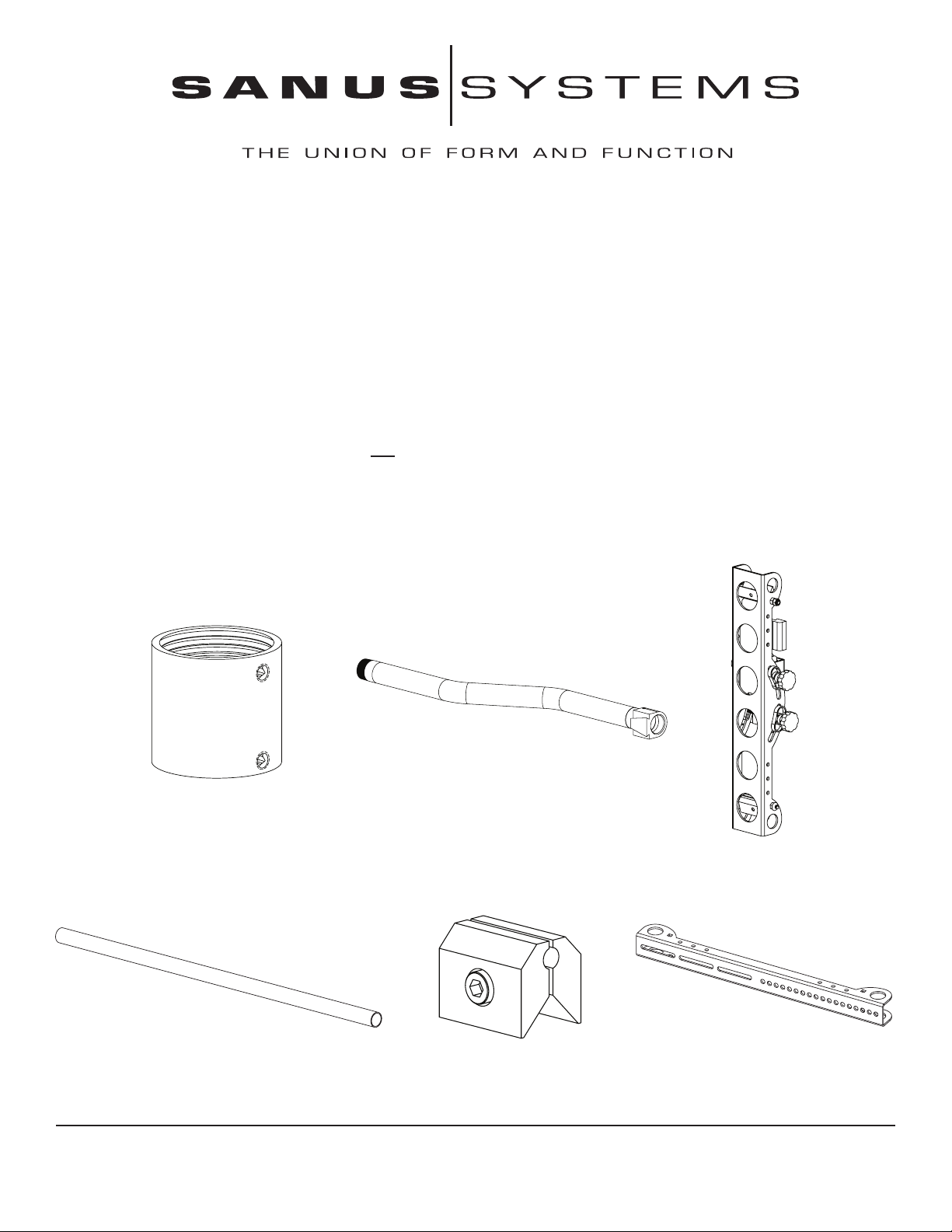
Supplied Parts and Hardware: Some parts not shown at same size*
(1) Coupler - a* (1) NPT Tube - b *
(1) Axis Assembly - c
(2) 1” Diameter Tube - d (4) Vise Assembly - e* (2) Monitor Bracket - f
Sanus Systems 2221 Hwy 36 West, St. Paul, MN 55113 10.18.05
Customer Service: 800.359.5520. See complementary Sanus products at www.sanus.com
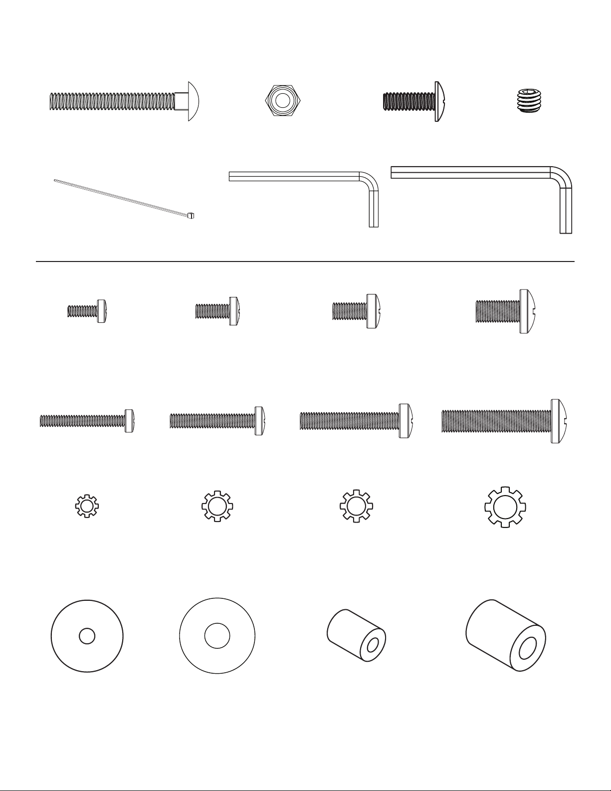
Hardware: Not shown at actual size*
(4) Carriage Bolt - g (4) 1/4 - 20 Nut - h (1) Security Bolt - i (2) Set Screw - j
(5) Wire Tie Clip - k* (1) Allen Key - l (1) Allen Key - m
TV Mounting Hardware: Shown as actual Size
(4) M4 x 12 mm Bolt - n (4) M5 x 12 mm Bolt - o (4) M6 x 12 mm Bolt - p (4) M8 x 16 mm Bolt - q
(4) M4 x 30 mm Bolt - r (4) M5 x 30 mm Bolt - s (4) M6 x 35 mm Bolt - t (4) M8 x 40 mm Bolt - u
(4) M4 Lock Washer - v (4) M5 Lock Washer - w (4) M6 Lock Washer - x (4) M8 Lock Washer - y
(4) M4/M5 Washer - z (4) M6/M8 Washer - aa (4) M4/M5 Spacer - bb (4) M6/M8 Spacer - cc
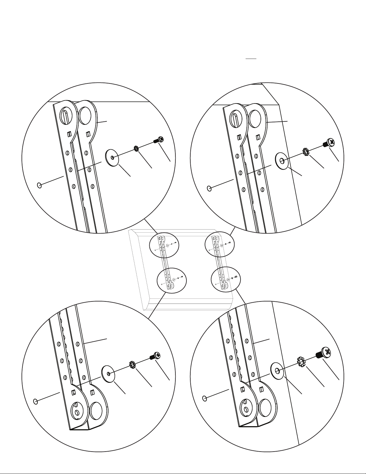
Step 1: Mounting Monitor Brackets to a television with a Flat Back
First, determine the diameter of the Bolt (n,o,p,q) your TV requires by hand threading them into the threaded insert on the back of the TV.
If you encounter any resistance stop immediately! Once you have determined the correct diameter, see the appropriate Diagram below. You
will thread the Bolt through the appropriate Lock Washer (v,w,x,y), a Washer (z,aa), the Monitor Bracket (f) and nally into the TV. Make
sure the Monitor Brackets are vertically centered and level with each other. Repeat process until each Monitor Bracket is secured to the TV
with 2 bolts. Note: For TVs with a curved back or any other obstruction See Step 2.
M4 Diameter M6 Diameter
f f
n p
v x
z aa
Diagram 1
M5 Diameter M8 Diameter
f f
o q
w y
z aa

Step 2: Mounting the Monitor Brackets to a television with a curved back or any other obstruction.
First, determine the diameter of the Bolt (r,s,t,u) your TV requires by hand threading them into the threaded insert on the back of the TV. If
you encounter any resistance stop immediately! Once you have determined the correct diameter, see the appropriate Diagram below. You
will thread the Bolt through the appropriate Lock Washer (v,w,x,y), a Washer (z,aa), the Monitor Bracket (f), through a Spacer (bb,cc) and
nally into the TV. Make sure the Monitor Brackets are vertically centered and level with each other. Repeat the process until each Monitor
Bracket is secured to the TV with 2 bolts.
M4 Diameter M6 Diameter
f f
r t
v x
z aa
bb
cc
Diagram 2
M5 Diameter M8 Diameter
f f
s u
w y
z aa
bb cc

Step 3: Add the Vise Assemblies to the Monitor Brackets:
Note: Do not overtighten the 1/4-20 Nut. The Vise Assembly should be able to rotate freely around the Carriage
Bolt.
Place the Vise Assembly (e) between the two sides of the Monitor Bracket (f) so that the two jaws point toward the set of 1” diameter
holes and the allen bolt is facing away from the television as shown in the Detailed View of Diagram 3. Place a Carriage Bolt (g) through
the square hole in the side of the Monitor Bracket, through the hole in the Vise Assembly, and then through the square hole in the other
side of the Monitor Bracket also shown in Diagram 3. Next, tighten a 1/4-20 Nut (h) onto the end of the Carriage bolt. Repeat this step
for the bottom of the Monitor Bracket. Finally, repeat these two steps for the second Monitor Bracket.
Detailed View
Diagram 3
allen bolt
e
f
g h
Step 4: Attach the Axis Assembly to the Television
Warning: The 1” Diameter Tubes must extend beyond the outside edges of both Monitor Brackets and the Allen
Bolts in all 6 Vise Assemblies must be tightened for the installation to be safe!
First, orient each Vise Assembly (e) so that a 1” Diameter Tube (d) will pass through the 1” round hole in the Monitor Bracket (f) and
then between the jaws of the Vise Assembly. Insert a 1” Diameter Tube through the top hole in the rst Monitor Bracket as shown in
Diagram 4. Repeat this step for the Bottom hole in the same Monitor Bracket.
Diagram 4
d
f
e

Step 5: Attach the Axis Assembly (cont)
Position the Axis Assembly (c) so that the allen bolts are facing away from the TV and the quick connect is on the top as shown in Diagram 5. Line up the two 1” diameter holes at the top and bottom of the Axis Assembly with the with the 1” Diameter Tubes (d). Continue
to push the 1” Diameter Tubes through the Vise Assembly on the Axis Assembly and then through the other Monitor Bracket (f). Again,
make sure the Vise Assemblies on both the Axis Assembly and the second Monitor Bracket are oriented so that the 1” Diameter Tubes
will pass between the jaws. Once the 1” Diameter Tubes are in place, tighten the allen bolts on the 4 Vise Assemblies in the two Monitor
Brackets with the Allen Key (m) to lock the television to the mount. Next, slide the Axis Assembly into the desired position between the
two Monitor Brackets and tighten the two remaining Vise Assemblies inside the Axis Assembly.
Note: Sanus recommends Axis Assembly to be centered between the Monitor Brackets.
Diagram 5
d
f c
e
vise assembly
Step 6: Attach Coupler
Thread the Coupler (a) onto the NPT Tube (b) until tight. See Diagram 6 for assistance.
Diagram 6
Detailed View
a
b

Step 7: Attach the NPT Tube
Front
To attach the NPT Tube (b), simply thread the Coupler (a) onto an existing NPT Tube. Make sure the lower NPT Tube is oriented so the
quick connect is facing toward the front as shown in the Side View of Diagram 7. Insert and tighten the Set Screws into each hole in the
coupler with the Allen Key (l) as shown in the Detailed View of Diagram 7.
Detailed View Diagram 7 Side View
existing
NPT tube
a
j
b
Step 8: Attach the Axis Assembly
To attach the two parts of the quick connect, slide the portion of the quick connect that is attached to the Axis Assembly (c) onto the
portion that is connected to the NPT tube. The two V shapes should form together so the Axis Assembly is secured to the tube. Proceed
to add the Security Bolt (i) on the top of the quick connect as seen in the Detailed View of Diagram 8.
Diagram 8
Detailed View
i

Step 9: Leveling and Tension
Once the television is mounted onto the NPT Tube (b), and the Security Bolt (i) is tight, it can be adjusted to level. Slightly loosen the
two allen bolts on the back of the Axis Assembly (c). Once those two bolts are loosened, the television can be adjusted ±6° until level.
When the television is level retighten the two allen bolts. The tilt can be adjusted by simply tilting the television. To increase or decrease
tension of the tilt, loosen the knobs that are labeled in Diagram 9. The Nut in the Detailed View can be slightly tightened or loosened to
adjust the tension of the Swivel. Once you have tilted the TV forward and removed the Safety Bracket, you can use the Safety Bracket
to adjust the tension. Make sure a at side of the tension nut is parallel with the TV before putting the Safety Bracket back on.
Detailed View Adjust Swivel Tension Diagram 9
tension
nut tension allen
knobs bolts
Step 10: Cable Management
Leave some slack in the cables so that during motion there is no added tension on the connectors. There are several places to attach Wire
Ties to keep cables out of the way. You can attach them to the holes in the sides of the Monitor Brackets (f), the Axis Assembly (c) or
around the NPT Tube (b). See Diagram 10 for assistance.
Diagram 10
Detailed View
f
k
Sanus Systems 2221 Hwy 36 West, St. Paul, MN 55113 10.18.05
Customer Service: 800.359.5520. See complementary Sanus products at www.sanus.com
 Loading...