

Assembly Instructions for Model: VMCC1
Thank you for choosing the Sanus Systems VMCC1. The VMCC1 is designed to mount a center channel speaker below a Sanus VMSA,
VMAA, VMAA18, VMAA26, VMDD or a VMDD26 Flat Panel Wall Mount.
Safety Warning: If you do not understand these directions, or have any doubts about the safety of the installation, please call a quali-
ed contractor or contact Sanus at 800.359.5520 or www.sanus.com. Check carefully to make sure that there are no missing or defective
parts. Our customer service representatives can quickly assist you with installation questions and missing or damaged parts. Replacement parts for products purchased through authorized dealers will be shipped directly to you. Never use defective parts. Improper instal-
lation may cause damage or serious injury. Do not use this product for any purpose that is not explicitly specied by Sanus Systems.
Sanus Systems can not be liable for damage or injury caused by incorrect mounting, incorrect assembly, or incorrect use. Please call
Sanus Systems before returning products to the point of purchase.
Required Tools: Phillips screw driver and crescent wrench.
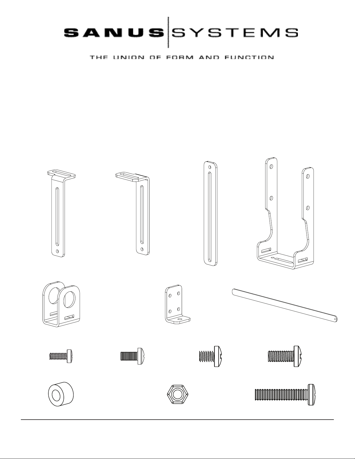
Supplied Parts and Hardware: Hardware shown as actual size.
(1) Left Upper Extension - a (1) Right Upper Extension- b
(2) Lower Extension - c (2) Axis Bracket - d
(2) Bar Bracket - e (2) Speaker Bracket - f (1) Support bar - g
(2) M4 x 10 Bolt - h (2) M5 x 10 Bolt - i (10) 1/4 - 20 x 3/8 Bolt - j (10) 1/4 - 20 x 5/8 Bolt - k
(2) Spacer - l (8) 1/4 - 20 Nut - m (2) 1/4 - 20 x 1500 Bolt - n
Sanus Systems 2221 Hwy 36 West, Saint Paul, MN 55113 11.16.05 (6901-100133)
Customer Service: 800.359.5520. See complementary Sanus products at www.sanus.com

For assembly information for the VMSA, VMAA, VMAA18 and VMAA26 see the Steps 1 through 6. For assembly
information for the VMDD and VMDD26 see Steps 7 through 12.
Step 1: Remove mount from Wall Plate and remove lower Cross Tube from the mount assembly.
Remove the mount from the wall plate. Loosen the Allen Bolts in the lower three Vise Assemblies and remove the lower Cross Tube
from the mount assembly. See Diagrams 1a and 1b below.
Diagram 1a Diagram 1b
vise assemblies
cross tube
Step 2: Add Axis Brackets
Position the Axis Bracket (d) so it ts over the Axis Assembly on the mount. Insert a 1/4 - 20 x 5/8 Bolt (k) through the Axis Bracket,
Axis Assembly and into a 1/4 - 20 Nut (m). Repeat process until the Axis Bracket is secured with four 1/4 - 20 x 5/8 Bolts and four 1/4
- 20 Nuts. Tighten each Bolt with a phillips screw driver until secure. See Diagram 2 below.
Detailed View Diagram 2
m
k
axis assembly
d
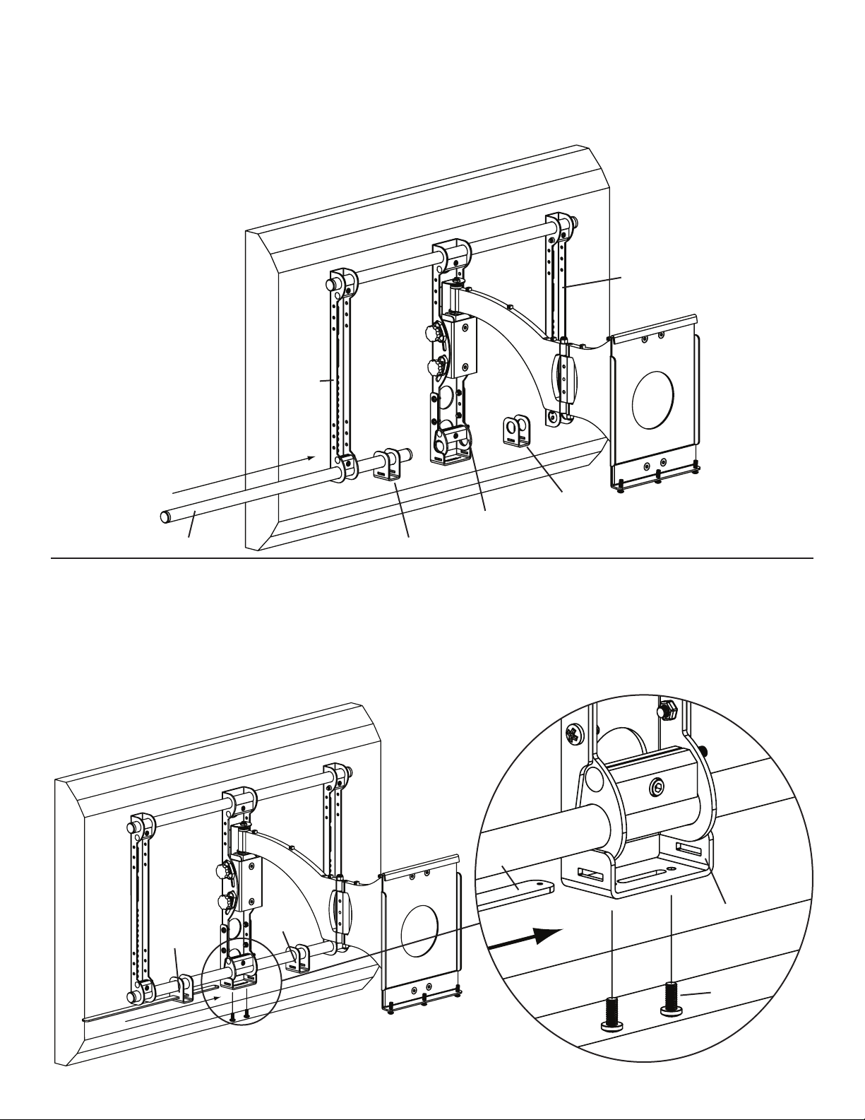
Step 3: Add Bar Brackets
Slide the lower Cross Tube through the Bar Bracket (e), the Axis Assembly, a second Bar Bracket and through the second Monitor
Bracket. Tighten all three Vise Assemblies secure the Cross Tube once it is slid through the second Monitor Bracket. See Diagram 3
below.
Diagram 3
monitor bracket
monitor
bracket
e
axis assembly
cross tube e
Step 4: Add Support bar
Slide the Support Bar (g) through the Bar Bracket (e), Axis Bracket (d) and through the other Bar Bracket. Make sure the Support Bar
is centered on the wall mount. Thread each 1/4 - 20 x 5/8 Bolt (k) through each hole in the bottom of the Axis Bracket until they bottom
out in the Support bar. See Diagram 4 below.
Diagram 4 Detailed View
g
d
e
e
k
 Loading...