

Assembly Instructions for Model: VMBR
Thank you for purchasing a Vision Mount product. This product is designed to hold a VCR, DVD player, or cable / satellite box under a
television wall mount. It will accommodate one component up to 15 lbs. Check carefully to make sure there are no missing or defective
parts. Never use defective parts. Improper installation may cause damage or serious injury. If you do not understand these directions,
or have any doubts about the safety of the installation, please call a qualified contractor or contact Sanus Systems at 800.359.5520 or
visit www.sanus.com. We can quickly assist you with installation questions and missing or damaged parts. Replacement parts for Sanus
products purchased through authorized dealers will be shipped directly to you.
Required Tools: Ratchet or wrench set
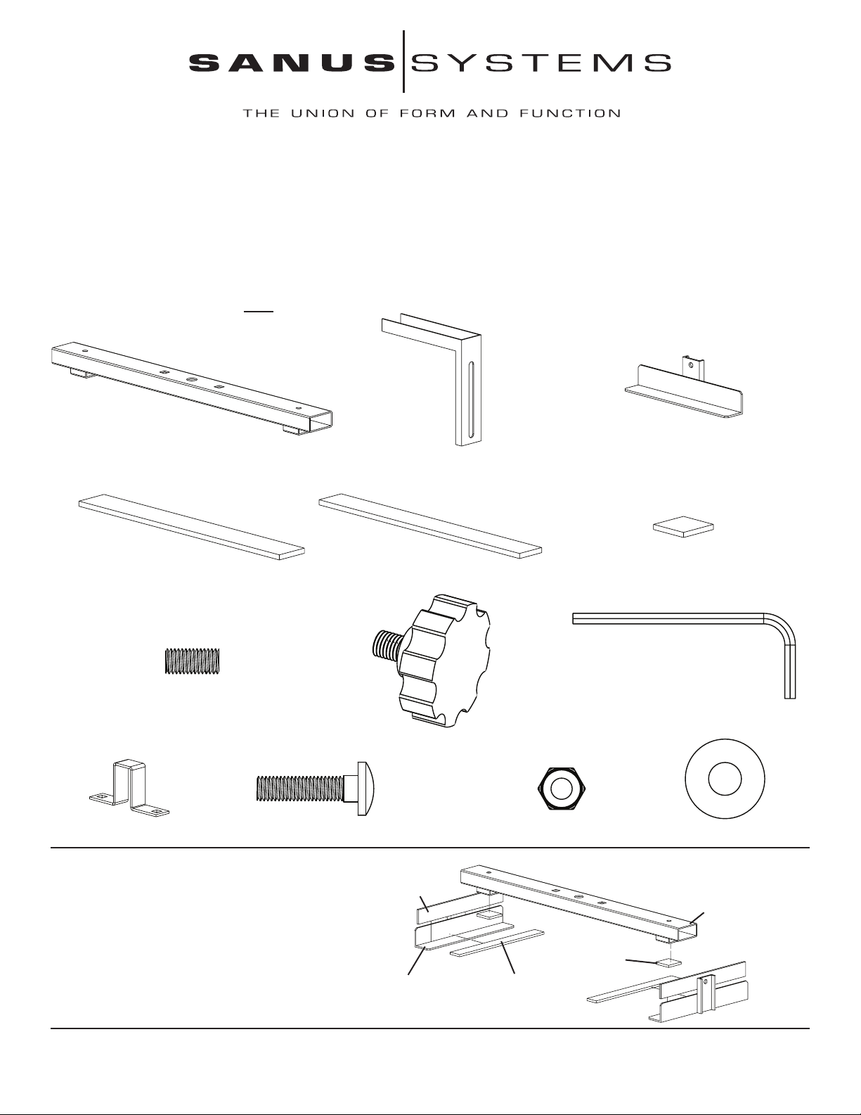
Supplied Parts: *Some parts NOT shown as actual size
(1) Main Arm - a* (2) Extension Arm - b* (2) Component Holder - c*
(2) 17 mm Wide Foam Pad - d* (2) 15 mm Wide Foam Pad - e* (2) Square Foam Pad - f*
(2) Set Screw - g (1) Allen Key - i
(2) Knob - h
(1) Mount Bracket - j* (2) 6 mm Diameter Bolt - k (2) 6 mm Diameter Nut - l (2) Washer - m
Step 1: Place the 2 Square Foam Pads (f) onto the 2 square
surfaces on the bottom of the Main Arm (a) as shown in
Diagram 1.
Place a 17 mm Wide Foam Pad (d) onto the vertical side
of each Component Holder (c). Next, place a 15 mm Wide
Foam Pad (e) onto the horizontal side of each Component
Holder as shown in Diagram 1.
d
a
f
c e
Diagram 1
Sanus Systems 2221 Hwy 36 West, Saint Paul, MN 55113 7.22.05
Customer Service: 800.359.5520. See complementary Sanus products at www.sanus.com
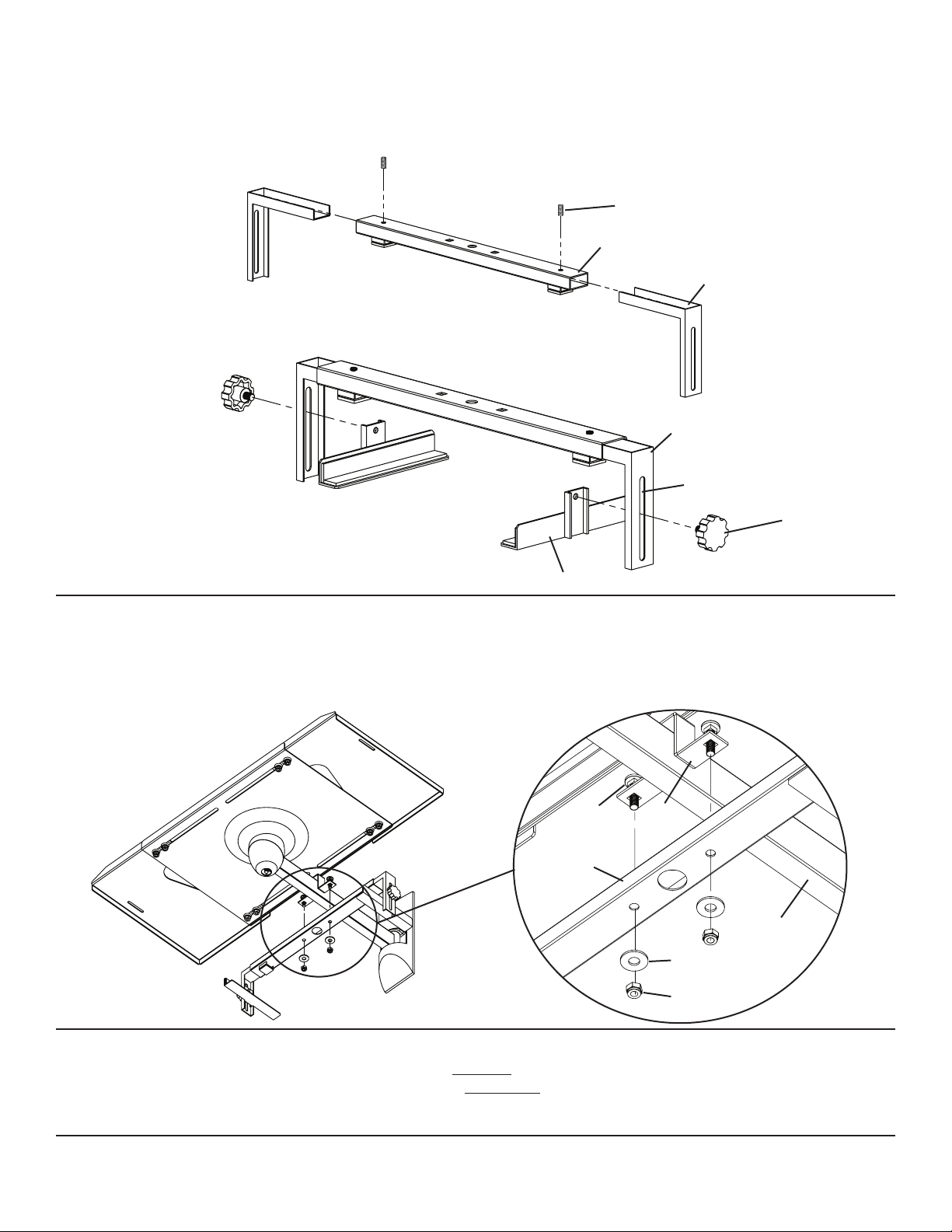
Step 2: Add an Extension Arm (b) to each side of the Main Arm (a). Lock each Extension Arm into place at the desired width using a
Set Screw (g). Tighten the Set Screw with the Allen Key (i). See Diagram 2 for assistance.
Step 3: A Component Holder (c) ts into the track on the inside of each Extension Arm (b). Insert a Knob (h) through the slot in the
Extension Arm from the outside and thread it into the hole in each Component Holder as shown in Diagram 3 below. Repeat process for
the other Component Holder.
Diagram 2
g
a
b
Diagram 3
b
slot
h
c
Step 4: Place the Mount Bracket (j) over the Arm of the TV wall mount. Place both 6 mm Diameter Bolts (k) down through the Mount
Bracket so that the square neck of the bolts t into the square holes in the bracket. Add the component bracket to the assembly so that
the two 6 mm Bolts (k) t down through the two square holes in the Main Arm (a), a Washer (m), and tighten a 6 mm Nut (l) onto each
6 mm Bolt. See the Detailed View of Diagram 4 for assistance. Tighten each Nut with the appropriate wrench or socket.
Diagram 4 Detailed View
k j
a
arm
m
l
Step 5: Adjustments can be made by:
•Adjusting the Knob (j) and sliding the Component Holders (c) vertically in the slot of the Extension Arm (b).
•Adjusting the Set Screws (g) and sliding the Extension Arms (b) horizontally inside the Main Arm (a).
Note: Adjust the bracket until the component is secured against the foam pads.
Sanus Systems 2221 Hwy 36 West, Saint Paul, MN 55113 7.22.05
Customer Service: 800.359.5520. See complementary Sanus products at www.sanus.com
 Loading...