

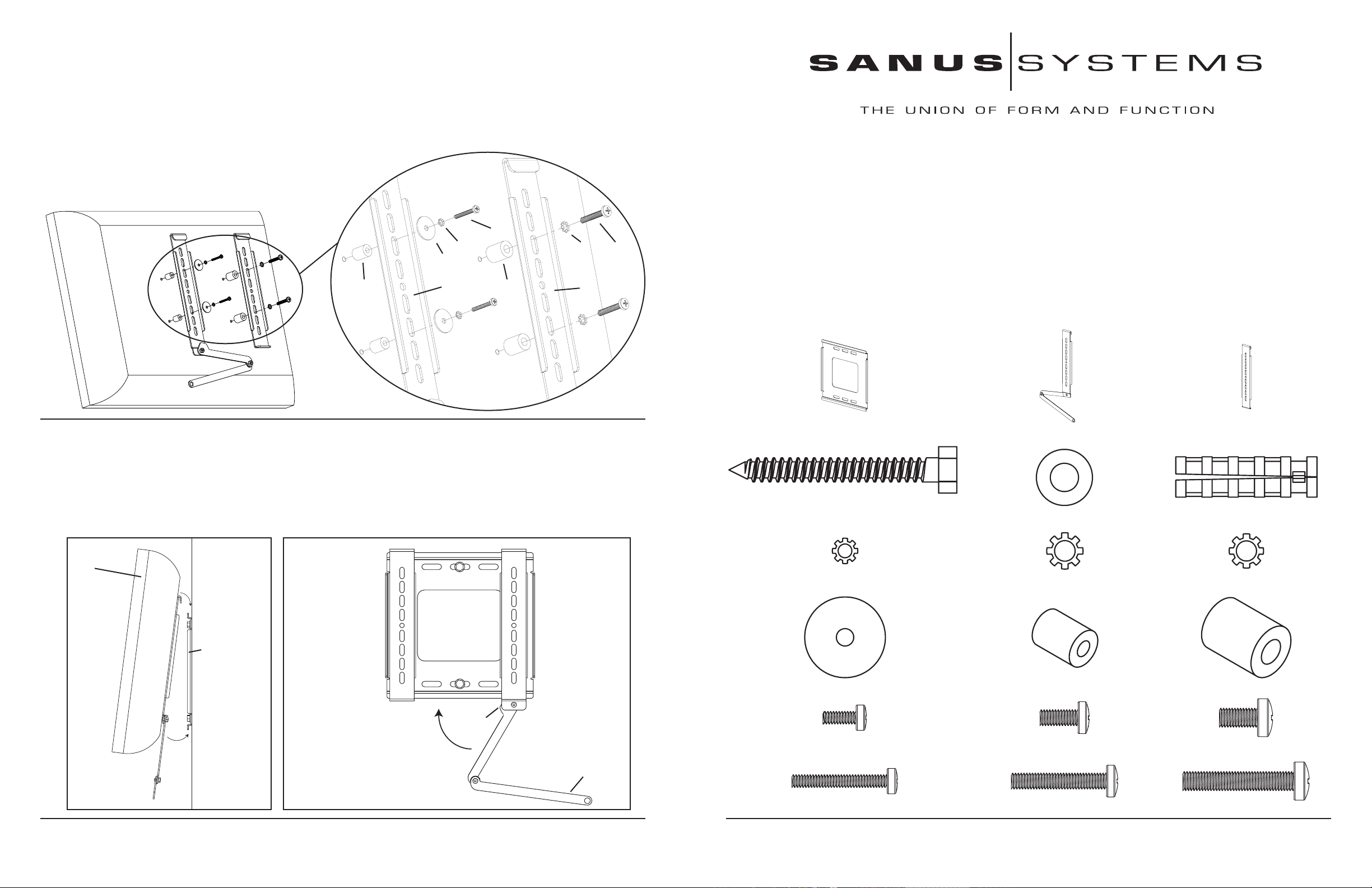
Step 4: Attach Monitor Brackets to a television with a curve, recess, or other obstuction on the back.
Make sure the Locking Monitor Bracket (b) is located on the left side as shown in Diagram 4. If your TV requires either a M4 or M5
diameter bolt, thread a M4 x 30mm (p) or a M5 x 30mm Bolt (q) through the appropriate Lock Washer (g,h), an M4/M5 Washer (j), the
Monitor Bracket (b,c), a M4/M5 Spacer (k) and into the TV as shown on the left side of the Detailed View of Diagram 4. If you determined that your TV requires a Bolt with a M6 Diameter, thread a M6 x 35 (r) Bolt through a Lock Washer (i), the Monitor Bracket, a M6
Spacer (l) and into the TV, as shown on the right side the Detailed View of Diagram 4 for assistance. Proceed to tighten the Bolts firmly
with a phillips screw driver. Detailed View
Assembly Instructions for Model VM300
Thank you for choosing a Sanus Systems Vision Mount wall mount. The VM300 is designed to mount up to 40” LCD flat panel televisions weighing up to 80 lb to a vertical wall. It will allow the television to be just .5” from of the wall.
Diagram 4
p,q
g,h i r
j
k b l c
Step 5: Hang television on the Wall Plate
Warning: Some televisions may require 2 people to lift! Sanus is not responsible for personal injury or product damage.
First hook the Monitor Brackets (b,c) over the top of the Wall Plate (a), then let the bottom of the Monitor Brackets rotate in under the
bottom of the Wall Plate as shown in Diagram 5a. Lock the television to the Wall Plate by moving the handle upward so the tab on the
handle goes behind the bottom of the Wall Plate as shown in Diagram 5b. Fold the handle extension up so that it hides behind the television.
Diagram 5a Diagram 5b
Safety Warning: If you do not understand these directions, or have any doubts about the safety of the installation, please call a qualified
contractor or contact Sanus at 800.359.5520 or www.sanus.com. Check carefully to make sure that there are no missing or defective
parts. Our customer service representatives can quickly assist you with installation questions and missing or damaged parts. Replacement parts for products purchased through authorized dealers will be shipped directly to you. Never use defective parts. Improper installation may cause damage or serious injury. Do not use this product for any purpose that is not explicitly specified by Sanus Systems.
Sanus Systems can not be liable for damage or injury caused by incorrect mounting, incorrect assembly, or incorrect use. Please call
Sanus Systems before returning products to the point of purchase.
Required Tools: Drill, 3/16” drill bit, (1/2” masonry bit for brick, concrete, or concrete block installations), wrench set, philips screw driver
Supplied Parts and Hardware: Some parts not shown as actual size*
(1) Wall Plate - a* (1) Locking Monitor Bracket - b* (1) Monitor Bracket - c*
(3) Lag Bolts - d (3) Lag Bolt Washer - e (3) Concrete Anchor - f
TV
a
wall
tab
extension handle
Sanus Systems 2221 Hwy 36 West, Saint Paul, MN 55113 10.04.04
Customer Service: 800.359.5520. See complementary Sanus products at www.sanus.com
(4) M4 Lock Washer - g (4) M5 Lock Washer - h (4) M6 Lock Washer - i
(4) M4/M5 Washer - j (4) M4/M5 Spacer - k (4) M6 Spacer - l
(4) M4 x 10mm Monitor Bolt - m (4) M5 x 12mm Monitor Bolt - n (4) M6 x 12mm Monitor Bolt - o
(4) M4 x 30mm Monitor Bolt - p (4) M5 x 30mm Monitor Bolt - q (4) M6 x 35mm Monitor Bolt - r
Sanus Systems 2221 Hwy 36 West, Saint Paul, MN 55113 10.04.04
Customer Service: 800.359.5520. See complementary Sanus products at www.sanus.com
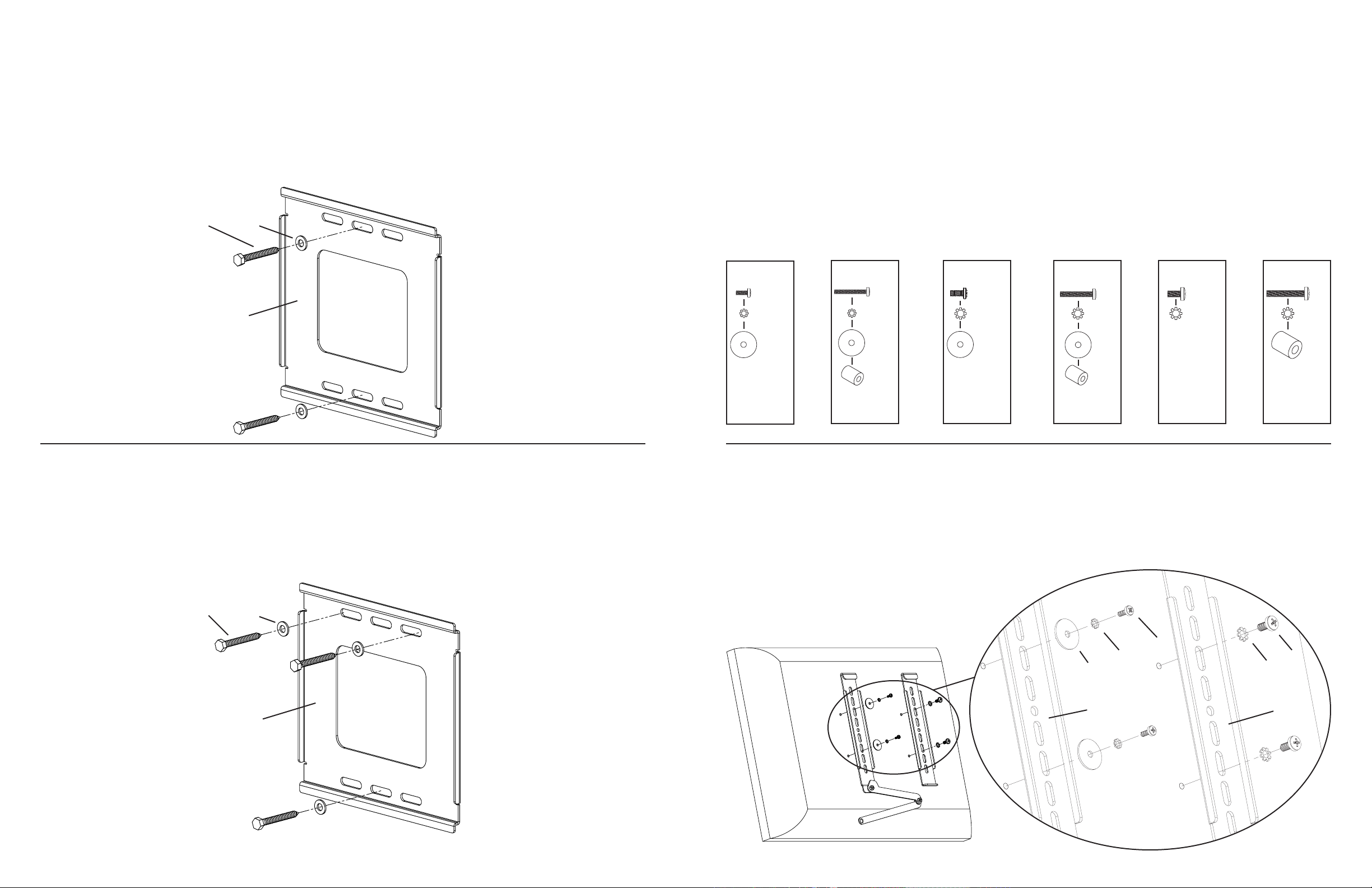
Step 1: Mount the Wall Plate: Wood Stud, Brick, Solid Concrete, and Concrete Block mounting options are provided.
Step 2: Select the Appropriate Hardware for your television
Wood Stud Mounting: The Wall Plate (a) must be mounted to a wood stud. Use a high quality stud sensor to locate a stud. Pre-drill
a 2.5” deep hole at the desired height in the stud using a 3/16” drill bit. Make sure the hole is in the center area of the stud. Use the Wall
Plate as a template to mark the location of the second hole. Make sure the Wall Plate is level and drill 2.5” a deep hole using the 3/16”
drill bit in the marked location. Attach the Wall Plate to the wall using two Lag Bolts (d) and two Lag Bolt Washers (e). Make sure the
Wall Plate is oriented so the flat surface in the center of the plate is against the wall as shown in Diagram 1a.
Warning: DO NOT OVERTIGHTEN THE LAG BOLTS! Tighten Lag Bolts only until the Lag Bolt Washer is pulled firmly
against the Wall Plate.
Diagram 1a
d e
a
Always make sure the television is unplugged before threading any bolt into the back panel!
Thread bolts carefully into your television by hand before tightening. If you feel resistance, remove the bolt immediately! If you
are unable to find appropriate hardware for your television, consult a local hardware store or call Sanus Systems.
Locate the threaded inserts on the back of your flat panel television and determine which of the provided Bolts is the correct diameter.
To test each diameter, thread the Bolts carefully into your television by hand until you find the diameter that correctly fits.
Next, determine the correct length of the required Bolt. Televisions with a flat back will require one of the shorter Bolts and no spacer.
Some televisions have a curve, recess, or other obstruction on the back. This may require a longer Bolt along with a Spacer placed between the television and the Monitor Bracket.
Once you have the correct bolt picked out, you can follow the diagrams below to see what additional hardware you will need to mount
the Monitor Brackets (b,c) to your television. For a television with a flat back, see Step 3 for installation instructions. For all other instances, see Step 4.
Hardware Diagrams: Parts are scaled.
M4 x 10
M4 x 30
M5 x 12
M5 x 30
M6 x 12
M6 x 35
m p n q o r
g g h h i i
j j j j l
k k
Brick, Solid Concrete and Concrete Block Mounting: Use the Wall Plate (a) as a template to mark 3 hole locations on the wall.
Always locate Concrete Anchors (f) in the brick, block, or concrete. Never drill into the mortar between blocks! The two top holes
should be as far to the outside of the Wall Plate as possible. The bottom hole should be in the center. Make sure theWall Plate is level.
Carefully pre-Drill these holes with a 1/2” masonry bit to at least 2.5” in depth. Insert a Concrete anchor into each of these holes. Make
sure the anchor is seated completely flush with the concrete surface even if there is a layer of drywall or other material in front. Attach
the Wall Plate to the wall using 3 Lag Bolts (d) and 3 Lag Bolt Washers (e). See Diagram 1b for assistance.
Warning: DO NOT OVERTIGHTEN THE LAG BOLTS! Tighten Lag Bolts only until the Lag Bolt Washer is pulled firmly
against the Wall Plate.
d e
a
Diagram 1b
Step 3: Attach Monitor Brackets to a television with a flat back
Make sure the Locking Monitor Bracket (b) is located on the left side as shown in Diagram 3. If your TV requires either an M4 or M5
diameter bolt, thread a M4 x 10mm (m) or M5 x 12mm Bolt (n) through the appropriate Lock Washer (g,h), an M4/M5 washer, the
Monitor Bracket (b,c) and into the TV as shown on the left side of the Detailed View of Diagram 3. If you have determined that your TV
requires an M6 diameter bolt, thread an M6 x 12mm Bolt (o) through a Lock Washer (i), the Monitor Brackets, and into the TV, as shown
on the right side of the Detailed View of Diagram 3 for Assistance. Proceed to tighten the Bolts firmly with a phillips screw driver.
Detailed View
m,n
g,h o
j i
b c
Diagram 3
 Loading...