

Sanus VLL5B1 Installation Manual

THANK YOU FOR CHOOSING SANUS
THE #1 TV MOUNT BRAND IN THE US.
VLL
5
Instruction Manual
Scan for easy
install video
SANUS
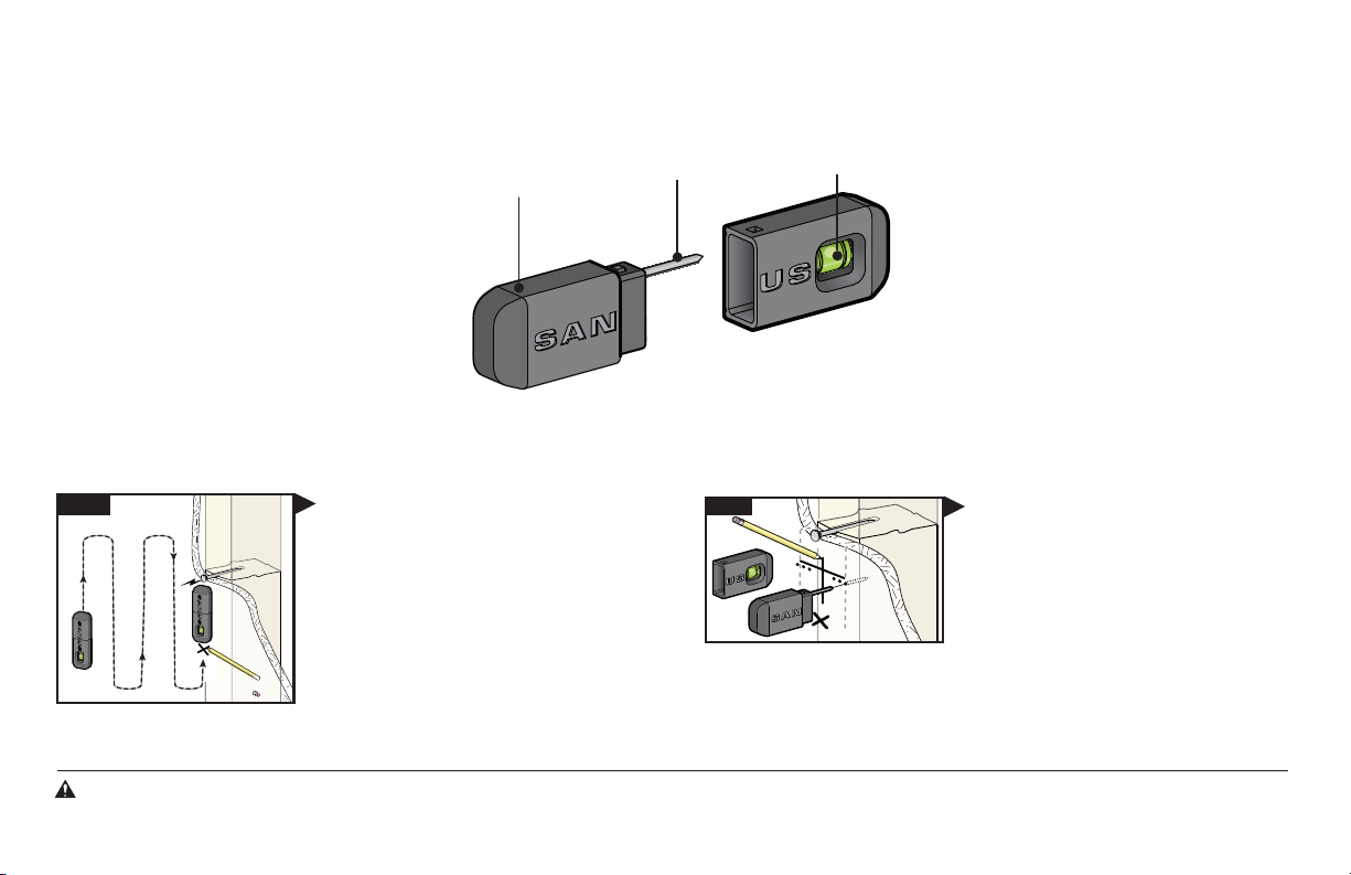
MAGNETIC STUD FINDER
Designed to find your studs and make life easier– included in hardware kit.
TWO SIMPLE STEPS
Step 1
locates screws in drywall
to show exactly where
your studs are
helps find the edges of
your stud within the wall
TO FINDING YOUR STUDS:
Holding it vertically, lightly move the SANUS
Magnetic Stud Finder up and down while
sliding across your wall. The magnet within
will be attracted to the screws in the stud.
Once the magnet has landed on a screw,
place a pencil mark on the wall
directly below the magnet.
You can verify this is a stud by moving the
Magnetic Stud Finder up or down to find
a second or third screw within the wall.
magnet
probing pin
Step 2
level
attaches to your wall plate
for hands free leveling
Pull apart the SANUS Magnetic Stud Finder to
expose the probing pin within. Starting about
1
/2 inch away from the first pencil mark insert
the probing pin into the wall every
it inserts completely into the wall. Once that
happens, you know you've found one edge of
your stud. Repeat this process till you have
found the stud edges and center of the stud.
1
/8 inch until
WARNING:This product contains a magnet. If an implanted medical device such as a pacemaker or implantable cardioverter defibrillator (ICD) is in use, magnetic fields may aect the operation of
those devices, resulting in serious injury or death. If you have an implanted medical device, keep at least 13 cm (5in.) between your device and the magnet. Please consult with your physician or medical
professional prior to using this product.
Para Español
ver página 24
VLL5
We’ll Make It Stress-Free
If you have any questions along the way, just give us a call.
1-800-359-5520 (UK: 0800-056-2853) We’re ready to help!
Lo haremos sin estrés
Si tiene preguntas mientras realiza la instalación, llámenos.
1-800-359-5520 (Reino Unido: 0800-056-2853) Estamos listos para ayudarlo.
3
IMPORTANT SAFETY INSTRUCTIONS – SAVE THESE INSTRUCTIONS – PLEASE READ ENTIRE MANUAL PRIOR TO USE
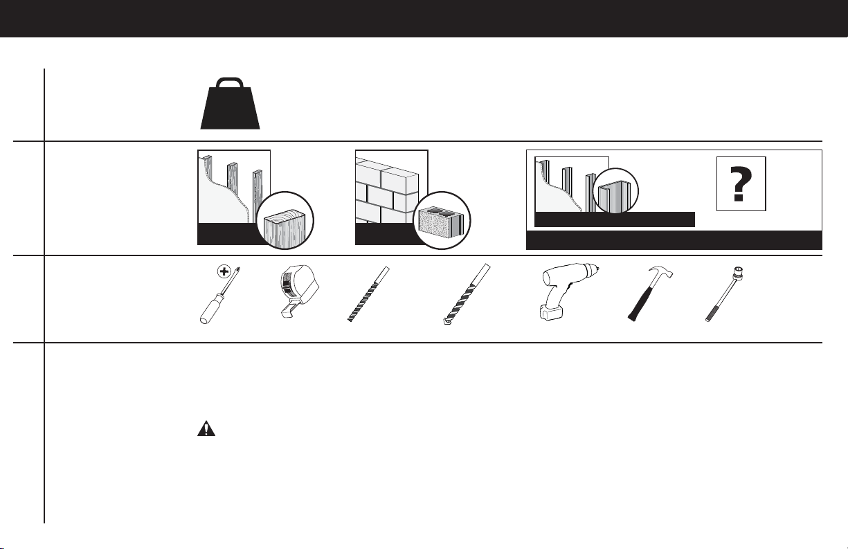
Before getting started, let’s make sure this mount is perfect for you!
1
2
3
4
4
Does your TV weigh
more than 125 lb
(56.7 kg) including
accessories?
What is your
wall made of?
Do you have
all the tools
needed?
Ready to
begin?
No — Perfect!
125 lb
(56.7 kg)
Perfect! Perfect!
Screwdriver Tape Measure Drill Bit Drill Bit Electric Drill Hammer Socket Wrench
Please read through these instructions completely to be sure you’re comfortable with this easy install process.
Also check your TV owner’s manual to see if there are any special requirements for mounting your TV.
If you do not understand these instructions or have doubts about the safety of the installation, assembly or use
of this product, contact Customer Service at 1-800-359-5520 (UK: 0800-056-2853).
CAUTION: Avoid potential personal injuries and property damage!
● This product includes directions and hardware for use with wood stud, solid concrete and concrete block walls –
DO NOT install into drywall alone. For information on how to use this product with steel stud walls contact Customer
Service and ask about the SSMK1 steel stud mounting kit.
● The wall must be capable of supporting fi ve times the weight of the TV and mount combined.
● Do not use this product for any purpose not explicitly specifi ed by manufacturer.
● Manufacturer is not responsible for damage or injury caused by incorrect assembly or use.
Yes — This mount is NOT compatible. Visit MountFinder.Sanus.com or call
1-800-359-5520 (UK: 0800-056-2853) to fi nd a compatible mount.
Drywall
with wood
studs?
7/32 in.
(5.5 mm)
Wood
Solid concrete
or concrete
block?
3/8 in.
(10 mm)
Concrete
Drywall
with steel
studs?
Steel stud kit (#SSMK1) required
Call Customer Service: 1-800-359-5520 (UK: 0800-056-2853)
1/2 in.
(13 mm)
Unsure?

STEP 1 Attach Bracket to TV
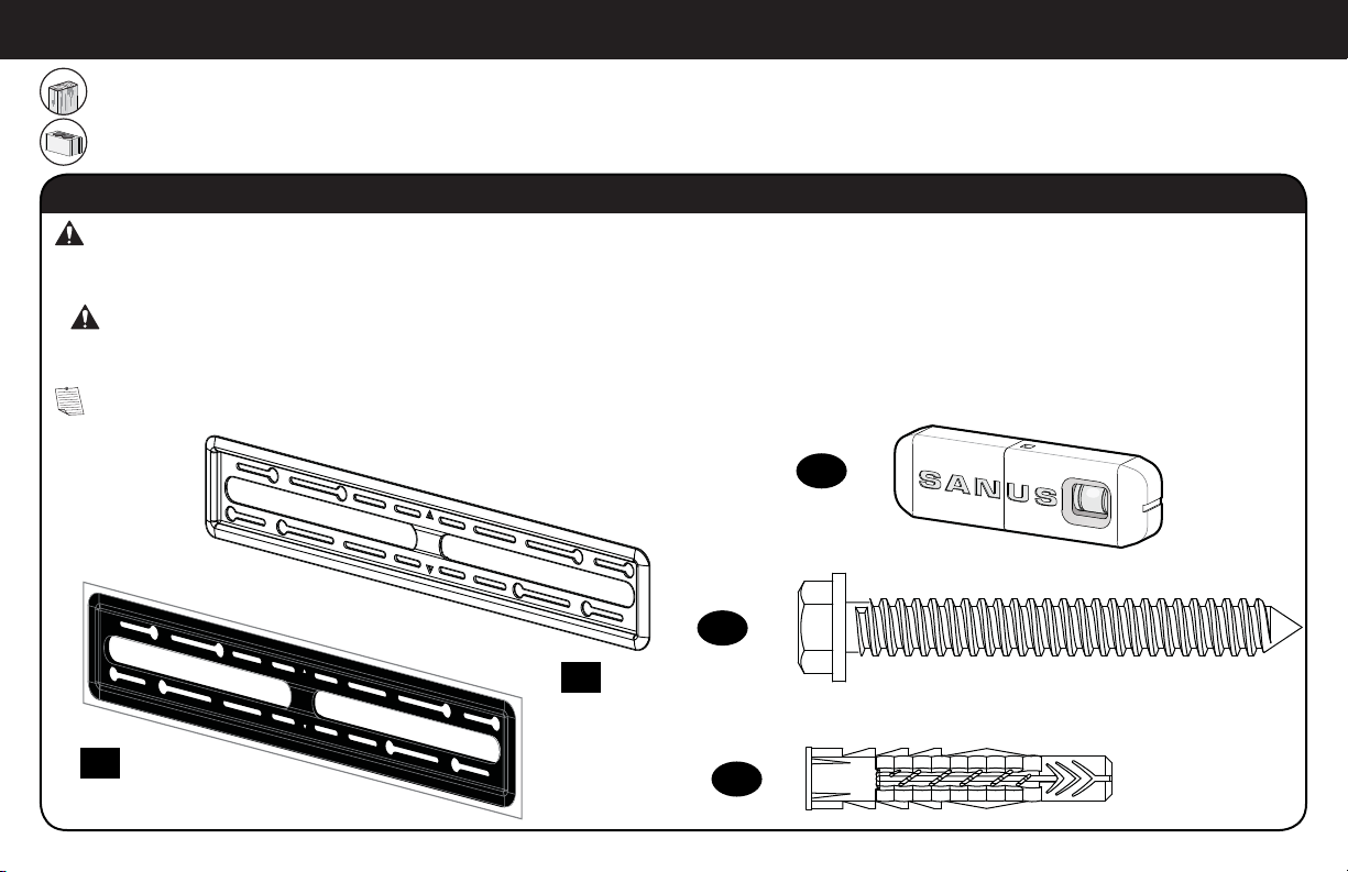
Parts and Hardware for STEP 1
WARNING: This product contains small items that could be a choking hazard if swallowed.
Before starting assembly, verify all parts are included and undamaged. If any parts are missing or damaged, do not return the damaged
item to your dealer; contact Customer Service. Never use damaged parts!
NOTE: Not all hardware included will be used.
TV Screws
TV Bracket
01
x2
M4 x 20mm
x4
02
M6 x 25mm
x4
04
TV Washers Spacers
x4 x4
07 08
M5 x 20mm
x4
03
M8 x 25mm
x4 x4
05 06
Spacer
09
M8x30 mm
x4
5
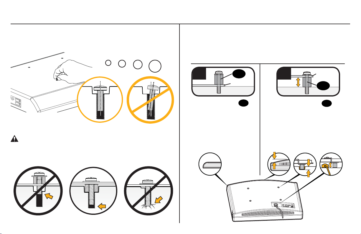
1-1 Select TV Screws
1-2 Spacers
Hand thread screws into the threaded inserts on the back of your TV
to determine which screw diameter (M4, M5, M6, or M8) to use.
M4 M6 M8M5
CAUTION: Verify adequate thread engagment of the screw/
spacer combination on your TV.
Too short will not hold the TV and too long will damage the TV.
Spacers and screws are supplied to install your TV bracket.
Determine your preference for spacer configuration when
attaching your TV bracket.
a
Mount the spacers
above the TV bracket,
so the TV bracket sits
close to the TV surface
for flat back panels.
09
TV Bracket
09
b
Mount the spacers 09
under the TV bracket to
create extra space needed
for irregular shape TV
backs or large cables.
Round Back CablesInset HolesFlat Back
TV Bracket
09
6
Too Short Correct Too Long
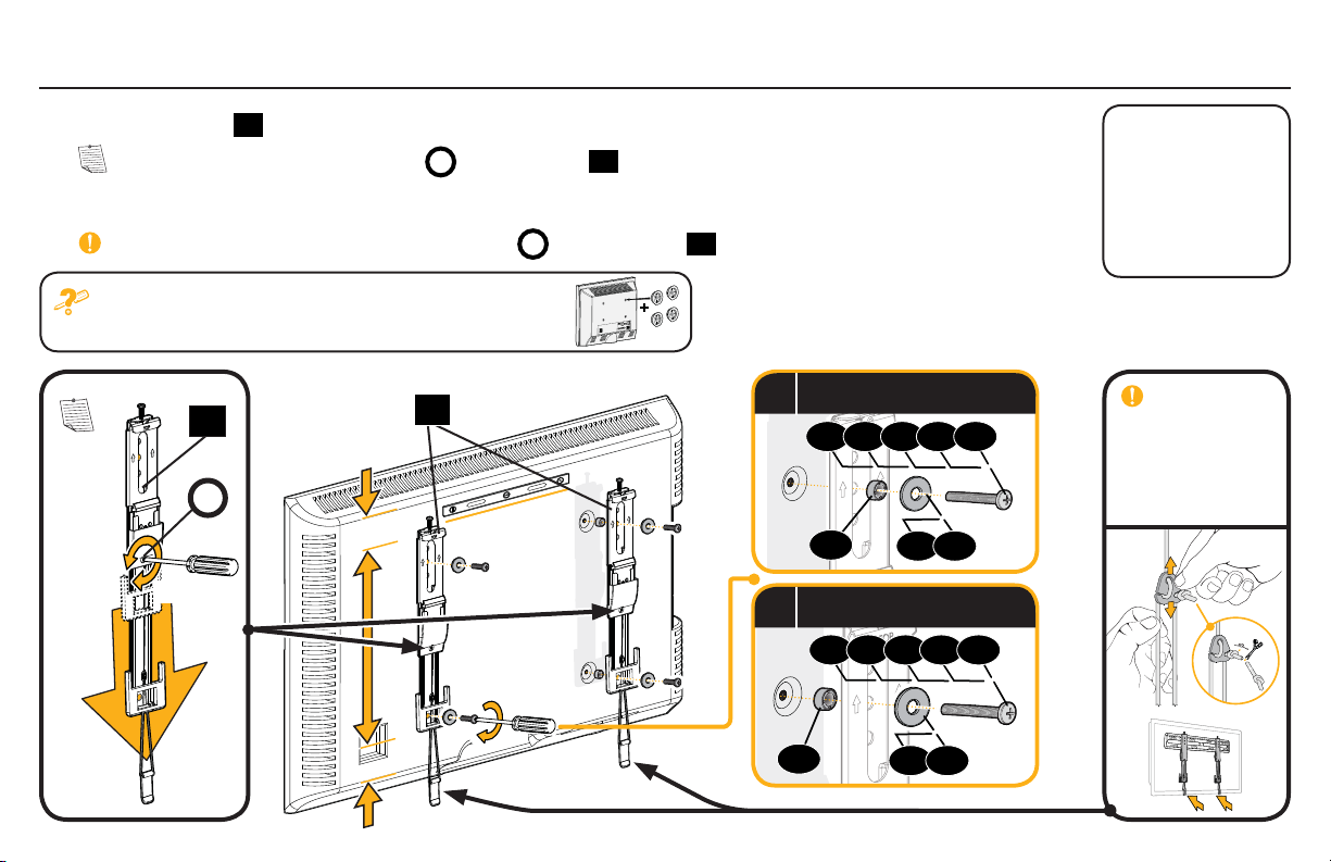
1-3 Attach TV Brackets
Center the TV brackets
NOTE: Loosen the adjustment screws
01
over your TV hole pattern as shown. Be sure to use the same holes and that the brackets are level.
on TV brackets
A
01
to extend the mounting holes over your TV hole pattern.
Install using the spacer, TV screw and washer combination you selected for your TV.
IMPORTANT: Tighten the adjustment screws
If your TV included inset spacers or wall mount adapters,
see Troubleshooting on PAGES 20-21.
01
01
on TV brackets
A
01
when finished.
A
Loosen
Tighten
Spacer, screw and washer
a
02 03 04 05 06
09
Spacer, screw and washer
b
07 08
02 03 04 05 06
Standard
configurations are
shown. For special
applications, or if
you are uncertain
about your hardware
selection, contact
Customer Service at
1-800-359-5520
.
IMPORTANT:
For ease of access,
straps should
be level with the
bottom of the TV.
09
07 08
7
STEP 2 Attach Wall Plate to Wall
For wood stud installations, follow STEP 2A on PAGE 9
For concrete installations, follow STEP 2B on PAGE 13
Parts and Hardware for STEP 2
WARNING: This product contains small items that could be a choking hazard if swallowed.
Before starting assembly, verify all parts are included and undamaged. If any parts are missing or damaged, do not return the damaged
item to your dealer; contact Customer Service. Never use damaged parts!
WARNING: This product contains a magnet. If an implanted medical device such as a pacemaker or implantable cardioverter defi brillator
*
(ICD) is in use, magnetic fi elds may a ect the operation of those devices, resulting in serious injury or death. If you have an implanted medical device,
keep at least 13 cm (5 in.) between your device and the magnet. Please consult with your physician or medical professional prior to using this product.
NOTE: Not all hardware included will be used.
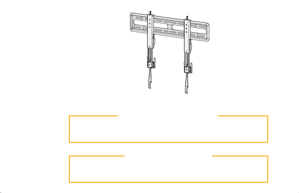
Wall Plate
Template
Wall Plate
13
x4
12
x1
Lag Bolt
Sanus Magnetic Stud Finder*
x1
11
x1
10
8
14
x4
5⁄16 in. x 2 3⁄4 in.
Concrete Anchor
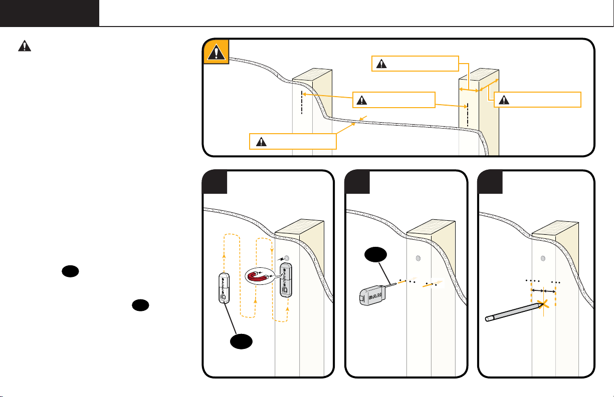
STEP 2A Wood Stud Option
CAUTION: Avoid potential
personal injuries and property damage!
● Drywall covering the wall must not
exceed 5/8 in. (16 mm)
● Minimum wood stud size:
common 2 x 4 in. (51 x 102 mm)
nominal 1½ x 3½ in. (38 x 89 mm)
● Minimum horizontal space between
fasteners: 16 in. (406 mm)
Max. 5/8 in. (16 mm)
Min. 1 1/2 in. (38 mm)
Min. 16 in. (406 mm)
Min. 3 1/2 in. (89 mm)
● Stud centers must be verified – not all
walls have conventional 16 in. (406 mm)
or 24 in. (610 mm) stud spacing
1. Locate a nail/screw in the studs
using the Sanus magnetic stud
finder 12 provided.
2. Find the edges of the studs using the
probe of the stud finder 12.
3. Mark the centers of the studs with
a pencil.
1 2 3
12
12
9
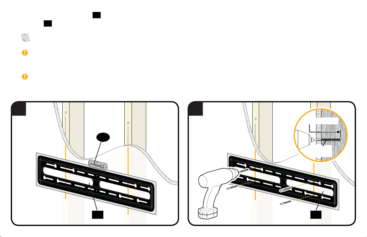
4. Place the wall plate template 10 at your desired height and position the slotted holes over your stud center lines. Level the wall plate
template 10 and tape in place.
NOTE: For assistance in determining wall plate location, see HeightFinder at sanus.com.
IMPORTANT: Be sure you mark and drill into the center of the stud.
5. Drill the four pilot holes using a 7/32 in. (5.5 mm) diameter drill bit.
IMPORTANT: Pilot holes must be drilled to a depth of 3 in. (75 mm).
4 5
3 in. (75 mm)
12
7/32 in.
(5.5 mm)
10 10
10
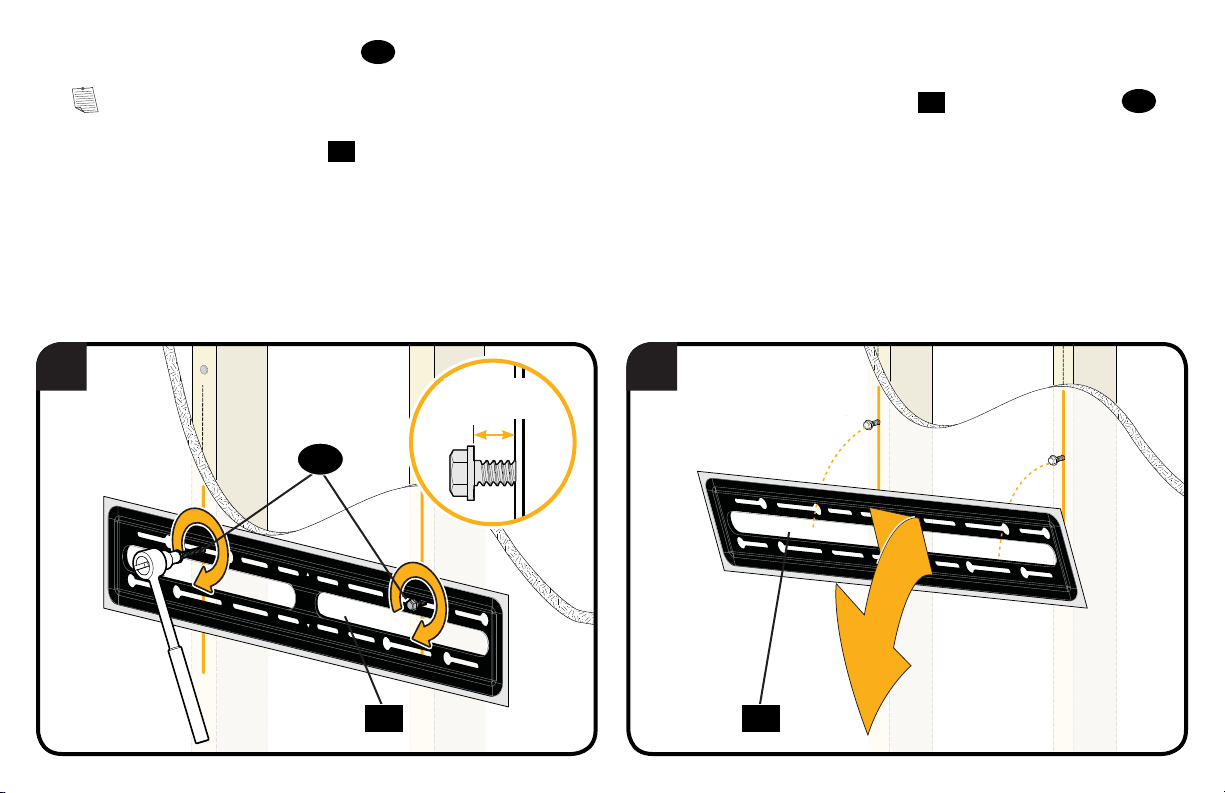
6. Partially install the top two lag bolts
13
leaving about 1/2 in. (13 mm) space from the wall.
,
NOTE: This is for 16 in. (406 mm) and 24 in. (610 mm) stud spacings, to allow you to hang the wall plate
7. Remove the wall plate template
6 7
10.
≈ 1/2 in.
(13 mm)
13
11
onto the top lag bolts 13.
10 10
11
 Loading...