

Page 1

Page 2

Page 3

TABLE OF CONTENTS
Instructions
Page 4
Page 5

Instructions
Page 6

Instructions
EXAMPLE OFANTENNA GROUNDINGAS PERTHE NATIONALELECTRICAL CODE
ANTENNALEADIN WIR E
ANTENNA
GROUND
CLAMP
ELEC TRICSERVICE
EQUIPMENT
NEC NATIONAL ELECTRICAL CODE
S2898A
DISCHAGRE UNIT
(NEC SECTIO N 810 20)
GROUNDING CONDUCTORS
(NEC SECTIO N 810 21)
GROUND CLAMPS
POWER SERVICE GROUNDING
ELECTRODE SYSTEM
(NEC ART 250,RARTH)
26) Where the mains plug is used as the disconnect device, the disconnect device shall
remain readily operable.
27) Explanation of symbol, marking, signal lamp or similar means indicate that apparatus
is completely disconnected from the mains. This equipment is a Class II or double
insulated electrical appliance. It has been designed in such a w ay that i t does not require a
safety connection to electrical earth.
28) Correct Disposal of this product. This marking indicates that this product should
not be disposed with other household wastes throughout the EU. To prevent possible harm
to the environment or human health from uncontrolled waste disposal, recycle it responsibly
to promote the sustainable reuse of material resources. To return your used device, please
use the return and collection systems or contact the retailer where the product was purchased.
Page 7
Instructions
Warning: batteries(pack or batteries installed) should not be exposed to excessive heat
such as sunshine, fire or other heat sources.
Page 8

Instructions
Page 9
below
Instructions
10cm
10cm
Page 10

TV Buttons and Connections
TV Buttons
Note: The following is only a r epresentat ion of the bu tto ns on your un it. The ac tual
posit ion a nd arrang ement of th e but tons may di ffer by mo del.
:Tu rn ON/OFF P ower.
SOURCE:External Signal Input Selection.
MENU:Display Main MENU And Confirm MENU Item Selection.
CH+/-:Select Channel.
VOL+/-:Adjust Volume .
Connections
INPUT
VIDEO R L
OUTPUT
VIDEO R L
INPUT
YPbPr
HDMI
AV input
External AV Signal Input and
Right/Left Audio Inputs.
AV Out pu t
External AV Signal Output and
Right/Left Audio Outputs.
Component Input
Con nect to a c omponent output
connection onyour external device.
HDMI Input
Con nect to a H DMI out put
connection onyour external device.
ANT 7 5/RF Co nnect ion
Connect tothe antenna/cable TV
output ofyour device orwall plate.
VGA Input
Connect toyour PC using a VGA
cable(not provided).
PC Audio Input
Con nect to y our PC Aud io Out
using 1/8line cord.
HEADPHONE JACK
HEADPHONE
COAXIAL
OUTPUT
R
OPTICAL
L
Plu g earph ones in to jack f or priv ate
listening. Overridesspeakers.
USB Input
Thi s input i s for ser vice pe rsonn el
only.
COAXIAL Output
Connect toyour SPDIF device
Output
Audio OutRight/Left
Connect toyour external device.
OPTICAL
Digital Audio Output.
8
Page 11
5V 0.5 A
Page 12
Install and Connect TV
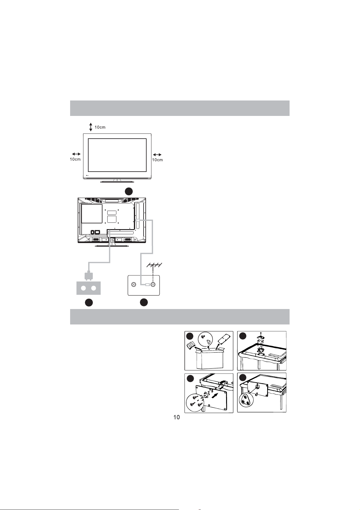
Set you r TV
1.Put y our TV in a place that can bear the
weigh t of th e TV.
To avoid danger, p lea se do not ass emble
the TV n ear water o r ext reme heat (such
as a furn ace , light sou rce,or ca ndl e.)
Do not bl ock t he ventil ation on the bac k
of the TV.
3
FMANT
TV signaloutput
2
TVANT
1
Conne ct an tenna and p owe r
2.Con nect the anten na cable to t he RF
connection on the back of the TV.
Plug th e TV into th e wal l power out let(
AC120 ~ 60Hz) .
Turn on t he TV
3.While in standby mode the power indication
light w ill b e red.Pre ss the powe r but ton on
the TV o r remote co ntr ol.The li ght will chang e
to gree n.
Note:
Picture for reference purposes only.
TV Stand Installation Instructions
TV Stand Installation Instructions
1. Open the carton and remove the TV,
accessories, and base.
2. To avoid injury to the TV, place the TV
face down on a firm surface, covered
with a soft cloth. Attach the neck to the
TV wit h the s upplied screws.
3. Attach the base to the neck with the
supplied screws.
4. Note: Insufficient tightening or incorrect
installation of the stand will not support
your unit correctly, and could result in
damage or injury from a tip-over.
1
3
2
4
Page 13

Select TV L oca tio n
TV Locatio n
Page 14
Page 15
Page 16

Powe r sa ving Prod uc es a lowe r power consumption mode.
/ Power saving
Page 17

Page 18

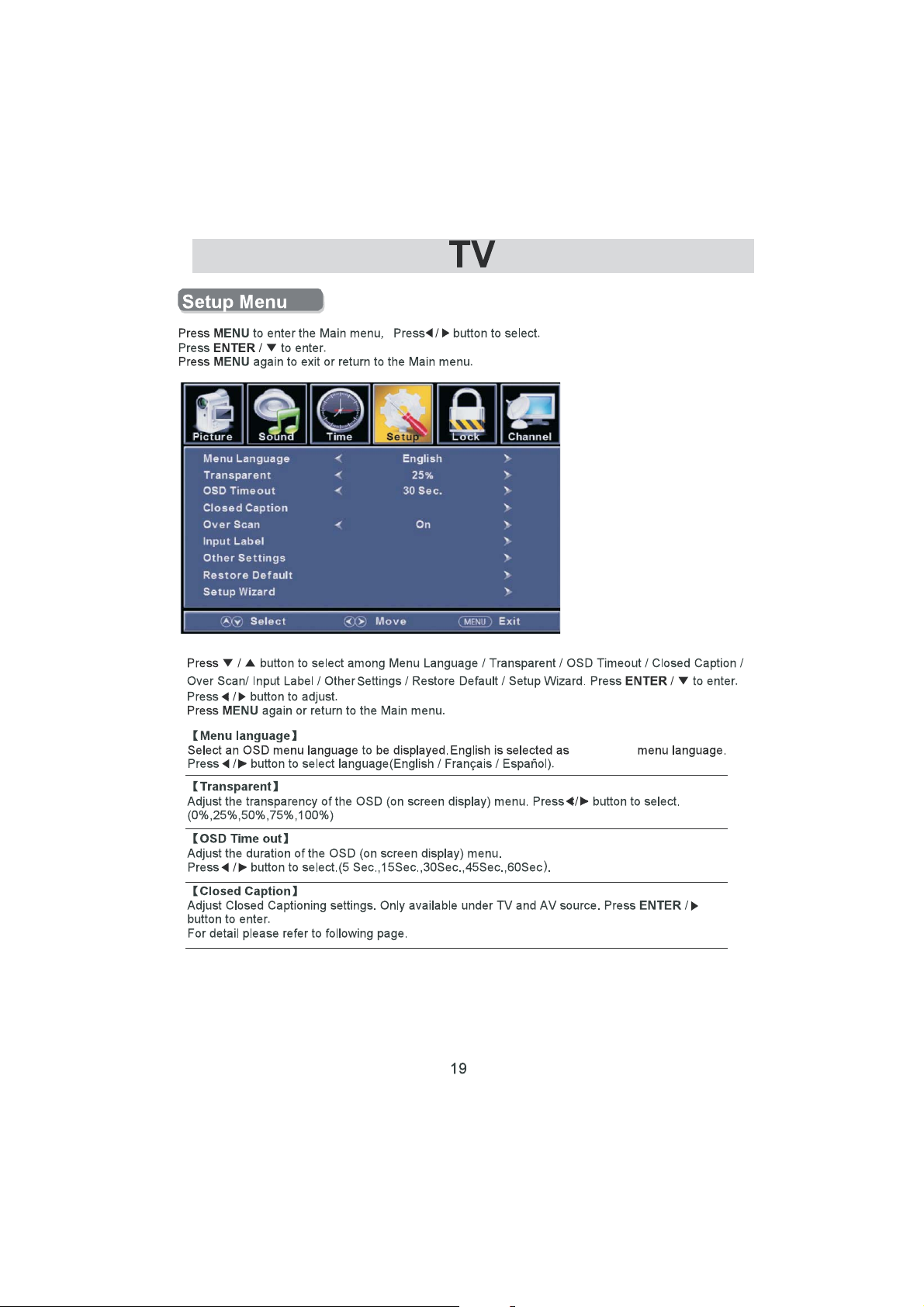
Page 19
Page 20

Page 21
the default
Page 22
Page 23

Page 24

Page 25

1-800-289-0980
Page 26

Page 27

All children
7 year s ol d and abo ve
General audience
Parental guidance
14 years old and above
17 years old and above
Page 28

MPAA
This system defines the rating control which come from MPAA rules.
Rating
Define
G
PG
PG 13
R
NC 17
X
Off
General audience. All ages admitted.
Parental guidance suggested. Some material may not be suitable for children.
Parents strongly cautioned. Some material may be inappropriate for children
under 13.
Restricted. Children under 17 require accompanying parent or adult guardian.
No one 17 and under admitted.
Adult audience only.
No Rating Set
Page 29

Page 30

Page 31

Page 32

Page 33

Page 34

inte rf er ing lin es .
Page 35

at the b ack o f the uni t
from
Page 36

Specifications
24”
28”
32”
39”
42”
50”
24”
28”
32”
39”
42”
50”
5W+5W
8W+8W
10W+10W
10W+10W
10W+10W
10W+10W
31W
31W
51W
76W
67W
108W
Page 37

1.Power: Set your TV to power on or standby mode.
2.MUTE: Press to mute the sound. Press again or press VOL+
3.0-9: Press 0 9 to select a TV channel directly when you are
4.- : Press “ ” to enter a program number for multiple program
to unmute.
watching TV.The channel will change after a few seconds.
channel, such as2 1etc.Return to the previous channel
viewed.
5. : Return to the previous channel viewed.
6.P.MODE: Press to cycle through the different picture settings.
7.SLEEP: Select the amount of time before TV turns off
automatically.
8.S.MODE: Press to cycle through the different sound settings.
9.MENU: Allows you to navigate the on screen menus.
10.SOURCE: Press to cycle through the input source in following:
TV → AV → YPBPR→ HDMI 1 → HD MI2 → HD MI3→PC
11. THUMBSTICK( / / / / ENTER):
Allows you to navigate the on screen menus and adjust the
system settings to your preference.
12.EXIT: Exit from the menu or sub menu and cancel the
13.DISPLAY: Press to display the source and channel’s
14.MTS: Press to select the audio mode,you can select Stereo,
function in progress (if possible).
information.
Mono,or SAP (second audio program).
15.V +/-: Press to increase or decrease the sound level.
16.CH+/-: Press to scan through or to select a channel.
17.AUT
O: Adjusting the PC image rate automatically.
18.FAV: Set or cancel current channel to be a favourite channel.
19.FAV+: Down move Favourite program.
20.FAV-: Up move Favourite program.
21.CC: Press to display the closed caption.
22.ZOOM: Select display mode.
10
15
Page 38

Page 39

Serial #
Date of Purchase
Place of Purchase
Your receipt is required to verify your proof of purchase, please
attach a copy of your receipt here for your records.
N° de série #
Date d’achat
Lieu d’achat
Votre reçu vous sera demandé pour vérifier votre
preuve
d’achat,
merci de bien vouloir joindre une copie de votre reçu ici pour
vos archives.
Page 40

TABLE DES MATIÈRES
Guide de préparation
Consignes de sécurité 2
Instructions de sécurité importantes 3-7
Installer et raccorder le téléviseur
Touches du téléviseur et connectivité 8
Schéma de connexion du périphérique externe 9
Installer et brancher le téléviseur 10
Instructions d'installation du pied du téléviseur 10
$VVLVWDQW GH FRQ¿JXUDWLRQ
$VVLVWDQW GH FRQ¿JXUDWLRQ 11-12
Sélectionner la source d'entrée
Sélectionner la source d'entrée 13
TV
Fonctionnement du menu principal 14-16
Menu son 16-17
Menu heure 18
0HQX GH FRQ¿JXUDWLRQ 19
Sous-titrage 20
Verrouillage du menu 23
&ODVVL¿FDWLRQ DPpULFDLQH 24
TV 24
MPAA 26
&ODVVL¿FDWLRQ FDQDGLHQQH 26
Menu hôtel 27-28
Menu des chaînes 29
PC
0HQX 3&
31-32
Autre information
Aide 33
Caractéristiques techniques 34
Schéma de la télécommande 35
1
Page 41

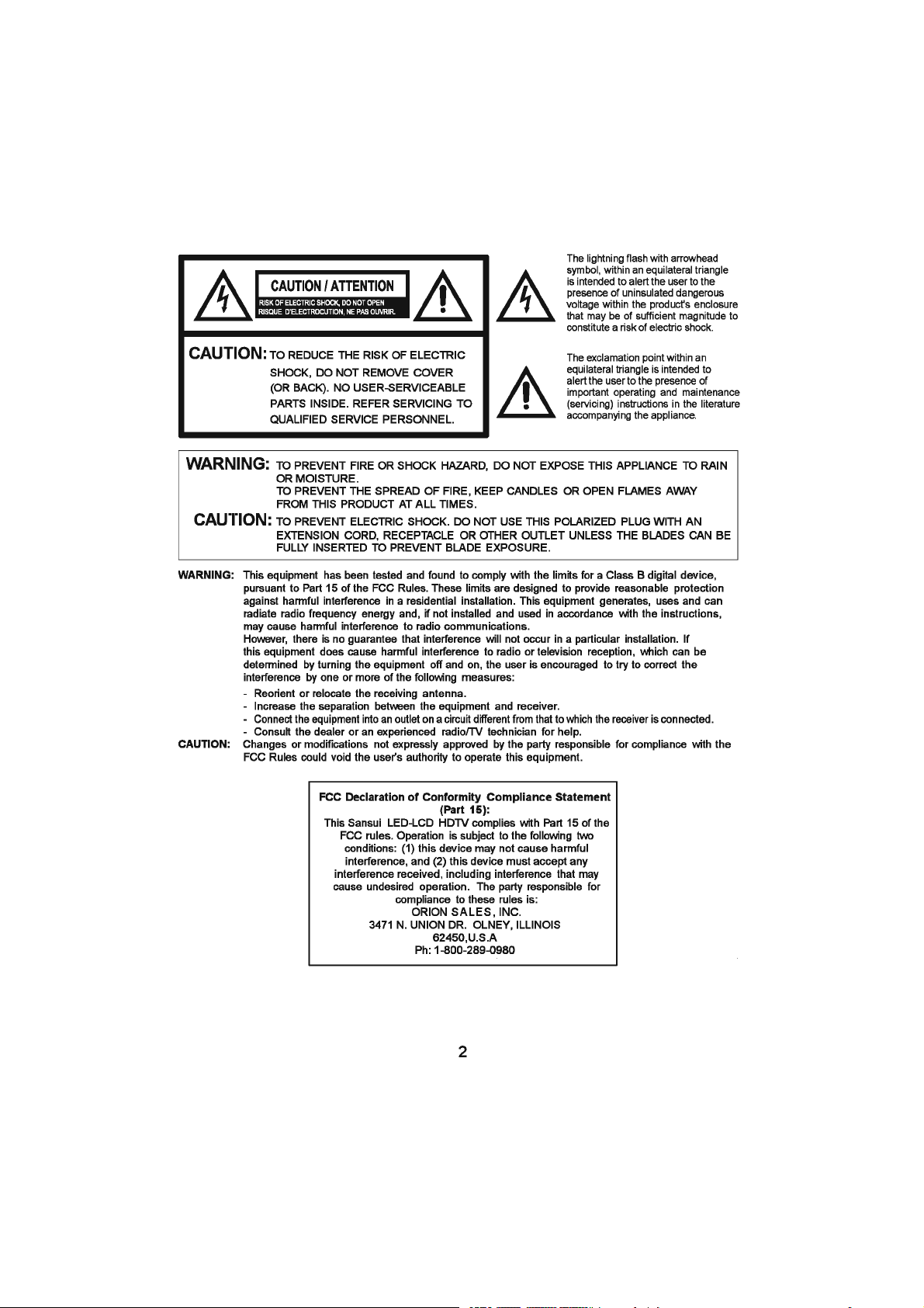
ATTENTION/PRÉCAUTIONS
RISQUE D'ÉLECTROCUTION, NE PAS OUVRIR.
RISQUE D’ÉLECTROCUTION, NE PAS OUVRIR.
Le symbole en forme d’éclair avec
XQH SRLQWH GH ÀqFKH GDQV XQ WULDQJOH
équilatéral est destiné à alerter
l'utilisateur de la présence dans l’appareil
d’un voltage non-isolé dangereux
SRXYDQW rWUH G¶XQH SXLVVDQFH VXI¿VDQWH
pour constituer un risque d’électrocution.
ATTENTION :
POUR RÉDUIRE LE RISQUE
D'ÉLECTROCUTION, NE PAS ENLEVER
LE COUVERCLE (OU L’ARRIÈRE).
AUCUNE PIÈCE RÉPARABLE PAR
L'UTILISATEUR À L'INTÉRIEUR.
ADRESSEZ-VOUS À UN TECHNICIEN
QUALIFIÉ POUR L’ENTRETIEN.
AVERTISSEMENT :
ATTENTION
AVERTISSEMENT :
POUR ÉVITER UNE ÉLECTROCUTION. NE PAS BRANCHER CETTE FICHE POLARISÉE DANS LA PRISE
D’UNE RALLONGE, D’UN RÉCEPTACLE OU D’UN AUTRE CONNECTEUR À MOINS QUE LES LAMELLES
PUISSENT ÊTRE TOTALEMENT INSÉRÉES AFIN D’ÉVITER TOUTE EXPOSITION.
Cet équipement a été testé et déclaré conforme aux limites d'un dispositif numérique de classe B,
conformément à la partie 15 des règles de la FCC. Ces limites sont conçues pour fournir une protection
raisonnable contre les interférences nuisibles dans une installation résidentielle. Cet équipement produit,
utilise et peut dégager une énergie de fréquence radio et, s'il n'est pas installé et utilisé conformément aux
instructions, il peut causer des interférences nuisibles aux communications radio.
Cependant, il n'est aucunement garanti que dans une installation particulière des interférences ne se
produisent pas. Si cet équipement provoque effectivement des interférences nuisibles à la réception
radiophonique ou télévisuelle, ce qui peut être déterminé en éteignant et en allumant l'équipement,
l'utilisateur est invité à essayer de corriger l'interférence par une ou plusieurs des mesures suivantes :
- Réorientez ou déplacez l'antenne de réception.
- Augmentez la distance entre l'équipement et le récepteur.
- Branchez l'équipement dans une prise faisant partie d'un circuit différent de celui auquel le récepteur est
raccordé.
- Consultez le revendeur ou un technicien radio/TV expérimenté pour obtenir de l'aide.
Le point d’exclamation dans un
triangle équilatéral est destiné à alerter
l'utilisateur de la présence d'instructions
d’utilisation et de maintenance (entretien)
importantes dans la documentation
accompagnant l'appareil.
POUR ÉVITER TOUT RISQUE D’INCENDIE OU D’ÉLECTROCUTION, NE PAS EXPOSER CET
APPAREIL À LA PLUIE OU À L’HUMIDITÉ.
POUR ÉVITER LA PROPAGATION DU FEU, GARDER TOUJOURS BOUGIES OU FLAMMES
LOIN DE CE PRODUIT.
ATTENTION :
/HV FKDQJHPHQWV RX PRGL¿FDWLRQV QRQ H[SUHVVpPHQW DSSURXYpV SDU OD SDUWLH UHVSRQVDEOH GH OD FRQIRUPLWp DX[
règlements de la FCC pourraient annuler le droit de l'utilisateur à utiliser cet équipement.
'pFODUDWLRQ )&& GH UHVSHFW GHV UqJOHV GH FRQIRUPLWp
(Partie 15) :
Ce téléviseur HD LED-LCD Sansui est conforme à la
partie 15 des règles de la FCC. Son fonctionnement est
soumis aux deux conditions suivantes : (1) ce dispositif
ne doit pas causer d'interférences nuisibles, et (2) cet
appareil doit accepter toute interférence reçue, y compris
les interférences qui peuvent provoquer un fonctionnement
indésirable. La partie qui est responsable de la conformité à
ces règles est :
ORION SALES, INC.
3471 N. UNION DR. OLNEY, ILLINOIS
62450,U.S.A Tél. : 1-800-289-0980
2
Page 42

Instructions de sécurité importantes
1. Lisez ces instructions.
2. Conservez ces instructions.
3. Respectez tous les avertissements.
4. Suivez toutes les instructions.
5. Ne pas utiliser cet appareil à proximité de l’eau.
6. Nettoyez uniquement avec un chiffon sec.
7. Ne jamais boucher les ouvertures de la ventilation. Installez l’unité conformément aux instructions
du fabriquant.
8 . Ne pas installer près d’une source de chaleur telle que des radiateurs, des registres de chaleur,
GHV SRrOHV RX G¶DXWUHV DSSDUHLOV \ FRPSULV GHV DPSOL¿FDWHXUV TXL SURGXLVHQW GH OD FKDOHXU
1H SDV FRQWRXUQHU OH GLVSRVLWLI GH VpFXULWp GH OD ¿FKH SRODULVpH RX GH PLVH j OD WHUUH 8QH ¿FKH
SRODULVpH D GHX[ ODPHV GRQW XQH SOXV ODUJH TXH O¶DXWUH 8QH ¿FKH GH WHUUH D GHX[ ODPHV HW XQH
broche de terre. La lame large ou la troisième broche sont fournies pour votre sécurité. Lorsque
OD ¿FKH IRXUQLH QH V¶LQVqUH SDV GDQV YRWUH SULVH FRQVXOWH] XQ pOHFWULFLHQ SRXU UHPSODFHU OD SULVH
obsolète.
10. Évitez que le cordon d’alimentation ne soit piétiné ou pincé, en particulier sur les prises, les
multiprises et au niveau de la sortie de l’appareil.
1¶XWLOLVH] TXH GHV ¿[DWLRQVDFFHVVRLUHV LQGLTXpV SDU OH IDEULFDQW
12. Utilisez uniquement avec le chariot, le stand, le trépied, le support ou la table
recommandée par le fabricant, ou vendu avec l’appareil. Lorsqu’un chariot est utilisé,
faites attention lors du déplacement de la combinaison du chariot/appareil pour éviter
de vous blesser en cas de chute.
13. Débranchez cet appareil pendant les orages ou lorsqu’il n’est pas utilisé pendant une longue
période.
&RQ¿H] WRXWH UpSDUDWLRQ j GX SHUVRQQHO TXDOL¿p 8QH UpSDUDWLRQ HVW QpFHVVDLUH ORUVTXH O¶DSSDUHLO
D pWp HQGRPPDJp GH TXHOTXH IDoRQ TXH FH VRLW SDU H[HPSOH VL OH FRUGRQ G¶DOLPHQWDWLRQ RX OD ¿FKH
sont endommagés, du liquide a été renversé ou des objets sont tombés dans l’appareil, l’appareil a
été exposé à la pluie ou à l’humidité, s’il ne fonctionne pas normalement, ou s’il est tombé.
15. Avertissement pour réduire le risque d’incendie ou de décharge électrique : ne pas exposer
cet appareil à la pluie ou à l’humidité. L’appareil doit être gardé à l’abri des gouttes ou des
éclaboussements d’eau ; ne posez jamais un objet contenant de l’eau sur cet appareil, par exemple
un vase.
16. Le système d’antenne extérieure ne devrait pas être situé à proximité de lignes électriques
aériennes ou d’autres circuits d’éclairage ou d’alimentation électrique, ou à un endroit où il
peut tomber sur ces lignes ou circuits électriques. Lors de l’installation d’un système d’ antenne
extérieure, prenez extrêmement soin de ne pas toucher ces lignes ou circuits électriques, car tout
contact peut être fatal.
17. Ne pas surcharger les prises murales et les câbles de rallonge, car cela peut entraîner des
risques d’incendie ou d’électrocution.
18. Ne pas introduire d’objets par les ouvertures de cet appareil, car ils pourraient entrer en contact
avec des points de tension dangereux ou court-circuiter des pièces qui pourraient provoquer des
incendies ou une décharge électrique. Ne jamais verser ou pulvériser de liquide quel qu’il soit sur
l’unité.
3
Page 43

Instructions de sécurité importantes
19) Si un système extérieur d'antenne ou de câble
est relié à l'appareil, assurez vous que le système
d'antenne ou de câble est mis à la terre pour fournir
une protection contre les surtensions et intégrer
l'électricité statique. L'article 810 de la norme du Code
national de l’électricité (National Electrical Code,
ou NEC), ANSI/NFPA 70, fournit des informations
concernant une mise à la terre adéquate du mât et
de la structure de support, la mise à la terre du câble
d'entrée vers une unité de décharge de l'antenne, la
taille des conducteurs de mise à la terre, la connexion
aux électrodes de terre et les exigences relatives aux
électrodes de terre.
20) En cas de remplacement de pièces, veillez à
ce que le technicien utilise des pièces recommandées par le fabricant ou des pièces présentant les mêmes
caractéristiques que les pièces d'origine. Toute substitution non conforme peut entraîner un incendie, un choc
électrique ou d’autres dangers.
21) Une fois l’opération d'entretien ou de réparation effectuée sur cet appareil, demandez au technicien
UHVSRQVDEOH GH OHQWUHWLHQ GHIIHFWXHU GHV FRQWU{OHV GH VpFXULWp D¿Q GH GpWHUPLQHU TXH ODSSDUHLO HVW HQ pWDW GH
fonctionner.
22) Lorsque vous branchez l'équipement à un autre appareil, mettez-le hors tension et débranchez tous les
équipements de la prise murale. Le non-respect de ces instructions peut entraîner un choc électrique et des
blessures graves. Lisez attentivement les modes d’emploi des autres appareils et observez les consignes lors
de tout branchement.
EXEMPLE DE MISE À LA TERRE CONFORMÉMENT AU CODE NATIONAL DE L ÉLECTRICITÉ,
CABLE D’ENTRÉE DE L’ANTENNE
ANTENNE
UNITÉ DE DÉCHARGE
(NEC SECTION 810-20)
CONDUCTEURS DE TERRE
(SECTION NEC 810-21)
PINCES DE TERRE
SYSTEME D'ÉLECTRODE DE MISE À
TERRE DU SERVICE ÉLECTRIQUE
(NEC ART 250, RARTH)
SERV CE ÉLECTRIQUE
NEC CODE ÉLECTRIQUE
NATIONAL S2898A
FIXATION
ÉQUIPEMENT
TERRE
23) Une hausse brutale du volume sonore peu être dangereuse pour l’ouïe et endommager les haut-parleurs.
Lorsque vous utilisez un casque, (si l'appareil est équipé d'une prise casque) gardez le volume à un niveau
modéré. Si vous utilisez un casque en permanence avec un niveau sonore élevé, cela peut causer des
dommages auditifs.
24) Ne laissez pas du son distordu se produire pour une durée prolongée. Cela peut provoquer la surchauffe
des haut-parleurs et un incendie.
25) Ce rappel est destiné à attirer l'attention de l’installateur de la téléviseur câblée sur l'article 820-40 du NEC
qui fournit des lignes directrices pour une mise à la terre adéquate. Il précise en particulier que le dispositif
de mise à la terre du câble doit être raccordé à un système de mise à la terre de l’immeuble aussi près que
possible de son point d’entrée.
26) Si la prise secteur est utilisée comme dispositif de déconnexion, le dispositif de déconnexion doit rester prêt
à l’emploi.
27) L’explication de symbole, le marquage, la lampe de signalisation ou des moyens similaires indiquent que
l'appareil est complètement déconnecté du secteur. Ce matériel appartient à la classe II ou un appareil
électrique à double isolation. Il a été conçu de telle sorte qu'il ne nécessite pas de connexion de sécurité à la
mise à la terre.
28) Élimination correcte de ce produit. Ce marquage indique qu’au sein de l’UE, ce produit ne doit pas être
jeté avec les autres déchets ménagers. Pour éviter toute atteinte à l'environnement ou à la santé humaine par
l'élimination incontrôlée des déchets, recyclez ce produit de façon responsable pour promouvoir la réutilisation
durable des ressources matérielles. Pour retourner votre appareil utilisé, veuillez suivre les procédures de
reprise et de collecte ou contactez le revendeur où le produit a été acheté. &HV GHUQLHUV SHXYHQW SURFpGHU DX
UHF\FODJH GX SURGXLW GDQV OH UHVSHFW GH O¶HQYLURQQHPHQW
4
Page 44

Instructions de sécurité importantes
SÉCURITÉ DES ENFANTS :
>ĞŵƉůĂĐĞŵĞŶƚ Ğƚ ůĂ ŵĂŶŝğƌĞ ĚŽŶƚ ǀŽƵƐ ƵƟůŝƐĞnj ƵŶ ƚĠůĠǀŝƐĞƵƌ ă ĠĐƌĂŶ ƉůĂƚ ĨŽŶƚ ƚŽƵƚĞ ůĂ
ĚŝīĠƌĞŶĐĞ
&ĠůŝĐŝƚĂƟŽŶƐ ƉŽƵƌ ǀŽƚƌĞ ĂĐŚĂƚ WĞŶĚĂŶƚ ƋƵĞ ǀŽƵƐ ƉƌŽĮƚĞnj ĚĞ ǀŽƚƌĞ ŶŽƵǀĞĂƵ ƉƌŽĚƵŝƚ ǀĞƵŝůůĞnj
ŐĂƌĚĞƌ ĐĞƐ ĐŽŶƐĞŝůƐ ĚĞ ƐĠĐƵƌŝƚĠ ă ůΖĞƐƉƌŝƚ
LA QUESTION
>ΖĞdžƉĠƌŝĞŶĐĞ ĚƵ ŚŽŵĞ ĐŝŶĠŵĂ ĞƐƚ ƵŶĞ ƚĞŶĚĂŶĐĞ ĐƌŽŝƐƐĂŶƚĞ Ğƚ ůĞƐ ƉůƵƐ ŐƌĂŶĚƐ ĠĐƌĂŶƐ ƉůĂƚƐ ƐŽŶƚ
ĚĞƐ ƌĠƵƐƐŝƚĞƐ ĐŽŵŵĞƌĐŝĂůĞƐ ĞƉĞŶĚĂŶƚ ůĞƐ ĠĐƌĂŶƐ ƉůĂƚƐ ŶĞ ƐŽŶƚ ƉĂƐ ƚŽƵũŽƵƌƐ ƐƵƌ ĚĞƐ ƉŝĞĚƐ
ĂĚĂƉƚĠƐ ŽƵ ŝŶƐƚĂůůĠƐ ĐŽŶĨŽƌŵĠŵĞŶƚ ĂƵdž ƌĞĐŽŵŵĂŶĚĂƟŽŶƐ ĚƵ ĨĂďƌŝĐĂŶƚ
>ĞƐ ĠĐƌĂŶƐ ƉůĂƚƐ ƋƵŝ ƐŽŶƚ ŵĂů ŝŶƐƚĂůůĠƐ ƐƵƌ ĚĞƐ ĐŽŵŵŽĚĞƐ ďŝďůŝŽƚŚğƋƵĞƐ ĠƚĂŐğƌĞƐ ďƵƌĞĂƵdž
ĞŶĐĞŝŶƚĞƐ ĐŽīƌĞƐ ŽƵ ĐŚĂƌŝŽƚƐ ƉĞƵǀĞŶƚ ƚŽŵďĞƌ Ğƚ ĐĂƵƐĞƌ ĚĞƐ ďůĞƐƐƵƌĞƐ
CE FABRICANT S’EN PRÉOCCUPE !
>ΖŝŶĚƵƐƚƌŝĞ ĠůĞĐƚƌŽŶŝƋƵĞ ŐƌĂŶĚ ƉƵďůŝĐ ƐΖĞŶŐĂŐĞ ă ƌĞŶĚƌĞ ůĞ ŚŽŵĞ ĐŝŶĠŵĂ ĂŐƌĠĂďůĞ Ğƚ ƐƸƌ
SOYEZ EN PHASE AVEC LA SÉCURITÉ
hŶ ƐĞƵů ŵŽĚğůĞ ŶĞ ĐŽŶǀŝĞŶƚ W^ ă ƚŽƵƐ ^ƵŝǀĞnj ůĞƐ ƌĞĐŽŵŵĂŶĚĂƟŽŶƐ ĚƵ ĨĂďƌŝĐĂŶƚ ƉŽƵƌ ƵŶĞ
ŝŶƐƚĂůůĂƟŽŶ Ğƚ ƵŶĞ ƵƟůŝƐĂƟŽŶ ĞŶ ƚŽƵƚĞ ƐĠĐƵƌŝƚĠ ĚĞ ǀŽƚƌĞ ĠĐƌĂŶ ƉůĂƚ
>ŝƐĞnj ĂƩĞŶƟǀĞŵĞŶƚ Ğƚ ĐŽŵƉƌĞŶĞnj ƚŽƵƚĞƐ ůĞƐ ŝŶƐƚƌƵĐƟŽŶƐ ũŽŝŶƚĞƐ ƉŽƵƌ ĨĂŝƌĞ ƵŶĞ ƵƟůŝƐĂƟŽŶ
ĂƉƉƌŽƉƌŝĠĞ ĚĞ ĐĞ ƉƌŽĚƵŝƚ EĞ ůĂŝƐƐĞnj ƉĂƐ ůĞƐ ĞŶĨĂŶƚƐ ŐƌŝŵƉĞƌ ŽƵ ũŽƵĞƌ ƐƵƌ ůĞƐ ŵĞƵďůĞƐ Ğƚ ůĞƐ
ƉŽƐƚĞƐ ĚĞ ƚĠůĠǀŝƐŝŽŶ
EĞ ƉůĂĐĞnj ƉĂƐ ůĞƐ ĠĐƌĂŶƐ ƉůĂƚƐ ƐƵƌ ĚĞƐ ŵĞƵďůĞƐ ƋƵŝ ƉĞƵǀĞŶƚ ĨĂĐŝůĞŵĞŶƚ ƐĞƌǀŝƌ ĚĞ ŵĂƌĐŚĞ
ĐŽŵŵĞ ƵŶĞ ĐŽŵŵŽĚĞ ă ƟƌŽŝƌƐ ƉĂƌ ĞdžĞŵƉůĞ
ZĂƉƉĞůĞnjͲǀŽƵƐ ƋƵĞ ůĞƐ ĞŶĨĂŶƚƐ ƉĞƵǀĞŶƚ ƐΖĂŐŝƚĞƌ ĞŶ ƌĞŐĂƌĚĂŶƚ ƵŶ ƉƌŽŐƌĂŵŵĞ ƐƵƌƚŽƵƚ ƐƵƌ ƵŶ
ĠĐƌĂŶ ƉůĂƚ ƉůƵƐ ŐƌĂŶĚ ƋƵĞ ŶĂƚƵƌĞ /ů ĨĂƵƚ ƉƌĞŶĚƌĞ ƐŽŝŶ ĚĞ ƉůĂĐĞƌ ŽƵ ĚΖŝŶƐƚĂůůĞƌ ůΖĠĐƌĂŶ ůă Žƶ ŝů
ŶĞ ƉĞƵƚ ƉĂƐ ġƚƌĞ ƉŽƵƐƐĠ ƟƌĠ ŽƵ ďĂƐĐƵůĠ
/ů ĨĂƵƚ ǀĞŝůůĞƌ ă ďŝĞŶ ƉŽƐŝƟŽŶŶĞƌ ƚŽƵƐ ůĞƐ ĮůƐ Ğƚ ůĞƐ ĐąďůĞƐ ĐŽŶŶĞĐƚĠƐ ă ůΖĠĐƌĂŶ ƉůĂƚ ĚĞ ƐŽƌƚĞ ƋƵΖŝůƐ
ŶĞ ƉƵŝƐƐĞŶƚ ƉĂƐ ġƚƌĞ ƟƌĠƐ ŽƵ ĂŐƌŝƉƉĠƐ ƉĂƌ ĚĞƐ ĞŶĨĂŶƚƐ ĐƵƌŝĞƵdž
ǀĞƌƟƐƐĞŵĞŶƚ ůĞƐ ƉŝůĞƐ ;ĞŶ ƉĂƋƵĞƚ ŽƵ ŝŶƐƚĂůůĠĞƐͿ ŶĞ ĚŽŝǀĞŶƚ ƉĂƐ ġƚƌĞ ĞdžƉŽƐĠĞƐ ă ƵŶĞ ĐŚĂůĞƵƌ
ĞdžĐĞƐƐŝǀĞ ƋƵĞ ĐĞ ƐŽŝƚ ůĞ ƐŽůĞŝů ůĞ ĨĞƵ ŽƵ ĚΖĂƵƚƌĞƐ ƐŽƵƌĐĞƐ ĚĞ ĐŚĂůĞƵƌ
5
Page 45

Instructions de sécurité importantes
CONDENSATION
De l’humidité se formera dans la partie motrice de l'appareil si celui-ci est transporté d'un milieu froid dans
une pièce chaude ou si la température de la pièce augmente soudainement. Lorsque cela se produit, l’unité
connaîtra une baisse de performance. Pour éviter cela, laissez l'appareil dans son nouvel environnement
pendant environ une heure avant de l'allumer, ou assurez-vous que la température de la pièce monte
progressivement.
De la condensation peut aussi se former en été si l'unité est exposée à la brise d'un climatiseur. Dans ce cas,
changer l’emplacement de l'unité.
COMMENT MANIPULER L'ÉCRAN LCD
Ne serrez pas trop fort et ne secouez pas l'écran LCD. Cela peut casser le verre de l'écran LCD et vous
blesser.
Si l'écran LCD est brisé, faites absolument attention à ne pas toucher le liquide à l’intérieur. Cela peut
FDXVHU XQH LQÀDPPDWLRQ GH OD SHDX
Si vous ingérez du liquide, gargarisez vous immédiatement et consultez votre médecin. En outre, si le
liquide entre en contact avec vos yeux ou votre peau, rincez au moins 15 minutes ou plus à l'eau propre puis
consultez un médecin.
Effets indésirables possibles sur l'écran LCD : 6L XQ PRWLI ¿[H QRQ PRELOH UHVWH VXU OpFUDQ /&' SHQGDQW
GH ORQJXHV SpULRGHV OLPDJH SHXW VH JUDYHU Gp¿QLWLYHPHQW VXU OpFUDQ /&' HW FDXVHU GHV LPDJHV IDQW{PHV
légères mais permanentes. Ce type de dommage N'EST PAS COUVERT PAR VOTRE GARANTIE. Ne laissez
MDPDLV YRWUH pFUDQ /&' DI¿FKHU ORQJWHPSV OHV IRUPDWV RX LPDJHV VXLYDQWV
/HV LPDJHV ¿[HV WHOOHV TXH OHV WDEOHDX[ GHV FRXUV GH OD ERXUVH GHV PRGqOHV GH MHX[ YLGpR GHV ORJRV
des chaînes de télévision et des sites Internet.
/HV IRUPDWV VSpFLDX[ TXL QH UHPSOLVVHQW SDV WRXW OpFUDQ 3DU H[HPSOH ODI¿FKDJHGLPDJHV HQ IRUPDW
SDQRUDPLTXH VXU XQ DI¿F
normal (4:3) sur un écran large (16:9) (barres noires sur les côtés gauche et droit de l'écran).
KDJH QRUPDO EDUUHV QRLUHV HQ KDXW HW HQ EDV GH OpFUDQ RX ODI¿FKDJH
/HV SKpQRPqQHV VXLYDQWV QH VRQW SDV GHV VLJQHV GH G\VIRQFWLRQQHPHQW PDLV GH OLPLWDWLRQ WHFKQLTXH
3DU FRQVpTXHQW QRXV GpFOLQRQV WRXWH UHVSRQVDELOLWp SRXU FHV SKpQRPqQHV
Les écrans LCD sont fabriqués en utilisant un très haut niveau de technologie de précision, mais parfois des
parties de l'écran peuvent être dépourvues d'éléments d'image ou présenter des points lumineux.
Ceci n'est pas un signe de dysfonctionnement.
N’installez l’écran LCD près d'un appareil électronique qui produit des ondes électromagnétiques. Certains
équipements, si placés trop près de cet appareil, peuvent provoquer des interférences.
Les effet sur les périphériques infrarouges - Il peut y avoir des interférences lors de l'utilisation de dispositifs
LQIUDURXJHV WHOV TXH OHV FDVTXHV VDQV ¿O LQIUDURXJHV
6
Page 46

Instructions de sécurité importantes
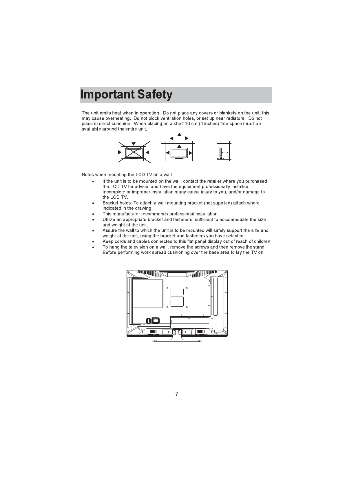
L'appareil émet de la chaleur lorsqu'il est en fonctionnement. Ne recouvrez pas l’appareil avec une couverture
RX TXRL TXH FH VRLW FHOD SHXW SURYRTXHU XQH VXUFKDXIIH 1¶REVWUXH] SDV OHV RUL¿FHV GH YHQWLODWLRQ HW QH SODFH]
pas l’appareil près d’un radiateur. Ne placez pas l’appareil en plein soleil. Si vous le placez sur une étagère
laissez un espace de 10 cm (4 pouces) autour de l'ensemble de l’installation.
10 cm
10 cm
Remarques pour le montage du téléviseur LCD sur un mur
Si l'appareil doit être monté sur un mur, contactez le détaillant où vous avez acheté
le téléviseur LCD pour obtenir des conseils, et faites installer l’équipement par des
professionnels. Une installation incomplète ou incorrecte peut causer des blessures et/ou
des dommages au téléviseur LCD.
/HV WURXV GH ¿[DWLRQ 3RXU ¿[HU XQ VXSSRUW PXUDO QRQ IRXUQL ¿[H] jOHQGURLW LQGLTXp VXU OH
dessin ci-dessous.
Ce fabricant recommande une installation professionnelle.
Utilisez des attaches et un support adéquats, en rapport à la taille et au poids de l'appareil.
Assurez-vous que le mur sur lequel l'appareil doit être monté sera adapté à la dimension et
DX SRLGV GH ODSSDUHLO DYHF OH VXSSRUW HW OHV ¿[DWLRQV TXH YRXV DYH] VpOHFWLRQQpV
0DLQWHQH] OHV ¿OV HW FkEOHV FRQQHFWpV j O¶pFUDQ SODW KRUV GH SRUWpH GHV HQIDQWV
Pour accrocher le téléviseur sur un mur, enlevez les vis puis retirez le pied. Avant d'effectuer
le travail étendez un rembourrage sous la base pour y déposer le téléviseur.
7
Page 47

Touches du téléviseur et connectivité
Les touches du téléviseur
Remarque : Ce qui suit est une simple représentation des touches de votre appareil.
La position réelle et la disposition des touches peuvent varier selon le modèle.
: Touche marche/arrêt (ON/OFF)
SOURCE : Sélection de l'entrée de signal externe.
MENU $I¿FKHU OH 0(18 SULQFLSDO HW 9DOLGHU OD VpOHFWLRQ GHV pOpPHQWV GX 0(18
CH +/- : Sélectionner la chaîne.
VOL+/- : Régler le volume.
Connectivité
Remarque : Voici les différentes connexions disponibles, la position réelle et la disposition et le nombre de chaque
type peuvent varier selon le modèle. Certains modèles ne possèdent pas toutes les connexions disponibles.
ENTRÉE
VIDÉO D G
SORTIE
VIDÉO D G
ENTRÉE
Y Pb Pr
HDMI
$17 ȍ
VGA
V entrée A
Entrée de signal AV externe et
entrées audio droite/gauche.
V sortie A
Sortie de signal AV externe et
sorties audio droite/gauche.
Entrée composante
Raccordez l’entrée compo
sante à une connexion de
sortie composante sur votre
périphérique externe.
Entrée HDMI
Reliez l’entrée HDMI à une
connexion de sortie HDMI sur
votre périphérique externe.
Connexion ANT 75/RF
Branchez la connexion ANT 75/
RF sur la sortie antenne/câble
TV de votre appareil ou de votre
console murale.
Entrée VGA
Reliez l’entrée VGA à votre PC
via un câble VGA (non fourni).
CASQUE AUDIO
USB
COAXIALE
SORTIE
D G
OPTIQUE
PRISE CASQUE
Branchez les écouteurs dans
la prise pour une écoute
privée. Cela coupe automati
quement les haut parleurs.
Entrée USB
Cette entrée est prévue pour
le personnel de maintenance
seulement.
Sortie COAXIALE
Reliez la sortie COAXIALE à votre
périphérique SPDIF
Sortie
Sortie audio droite/gauche
Branchez la sortie sur votre périphé
rique externe.
OPTIQUE
Sortie audio numérique.
AUDIO PC
ENTRÉE
Entrée audio PC
Reliez l’entrée audio PC
à la sortie audio de votre
PC en utilisant le cordon
d'alimentation 1/8.
8
Page 48

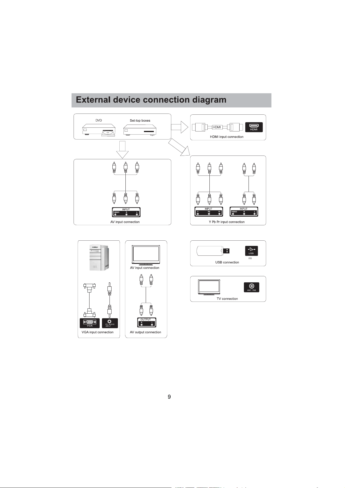
6FKpPD GH FRQQH[LRQ GX SpULSKpULTXH H[WHUQH
DVD
Boîtiers décodeurs
numériques
Connexion d'entrée AV
Connexion d'entrée HDMI
Connexion d'entrée Y Pb Pr
Connexion d'entrée AV
Connexion de sortie AV Connexion d'entrée VGA
5V 0,5A
Connexion USB
Connexion TV
9
Page 49

Installer et raccorder le téléviseur
5pJOH] YRWUH WpOpYLVHXU
1. Placez votre téléviseur dans un endroit qui
peut supporter son poids.
Pour éviter tout danger, veuillez ne pas
monter le téléviseur près d’un point d'eau
ou d’une chaleur extrême (comme un four,
une source de lumière ou une bougie).
Ne bloquez pas la ventilation à l'arrière du
téléviseur.
2
3
ANT FM
Sortie du signal TV
1
Branchez le cordon d'alimentation et l'antenne
2. Branchez le câble d'antenne dans la prise RF
à l'arrière du téléviseur. Branchez le téléviseur
dans la prise de courant murale
(AC 120~ 60 Hz).
Allumez le téléviseur
3. En mode veille, le voyant d’alimentation est
rouge. Appuyez sur la touche d'alimentation
sur le téléviseur ou la télécommande. La
lumière passera au vert.
5HPDUTXH
Image pour référence seulement.
ANT TV
Instructions d’installation du pied du téléviseur
Instructions d’installation du pied du téléviseur
1. Ouvrez le carton et sortez le téléviseur, les
accessoires et la base.
2. Pour éviter tout risque de dommage au téléviseur,
placez-la face au sol sur une surface ferme,
couverte d’un chiffon doux. Fixez la jambe au
téléviseur avec les vis fournies.
3. Fixez la base à la jambe avec les vis fournies.
4. 5HPDUTXH 8Q VHUUDJH LQVXI¿VDQW RX XQH
mauvaise installation du pied ne pourront pas
soutenir votre appareil correctement, et peuvent
provoquer des dégâts ou des blessures si le
téléviseur bascule.
1
3
10
2
4
Page 50

$VVLVWDQW GH FRQ¿JXUDWLRQ
Reliez la prise de votre source antenne/câble à l'entrée du téléviseur marquée « ANT » par un câble RF.
Sélectionnez l’emplacement du téléviseur
Appuyez sur la touche W / X pour sélectionner l'emplacement du téléviseur qui va être utilisé.
$SSX\H] VXU OD WRXFKH źŸ SRXU VpOHFWLRQQHU $OOHU j OpWDSH VXLYDQWH HW DSSX\H] VXU (175(5Ź
Sélectionnez Heure
$SSX\H] VXU OD WRXFKH źŸ SRXU VpOHFWLRQQHU OH WLPH ]RQH O¶KHXUH G¶pWp HW IRUPDW GH O¶KHXUH TXH YRXV SUpIpUH]
Appuyez sur la touche W / X de la télécommande pour ajuster.
$SSX\H] VXU OD WRXFKH źŸ VXU OD WpOpFRPPDQGH SRXU VpOHFWLRQQHU $OOHU j O¶pWDSH VXLYDQWH HW DSSX\H] VXU (175(5 Ź
11
Page 51

$VVLVWDQW GH FRQ¿JXUDWLRQ
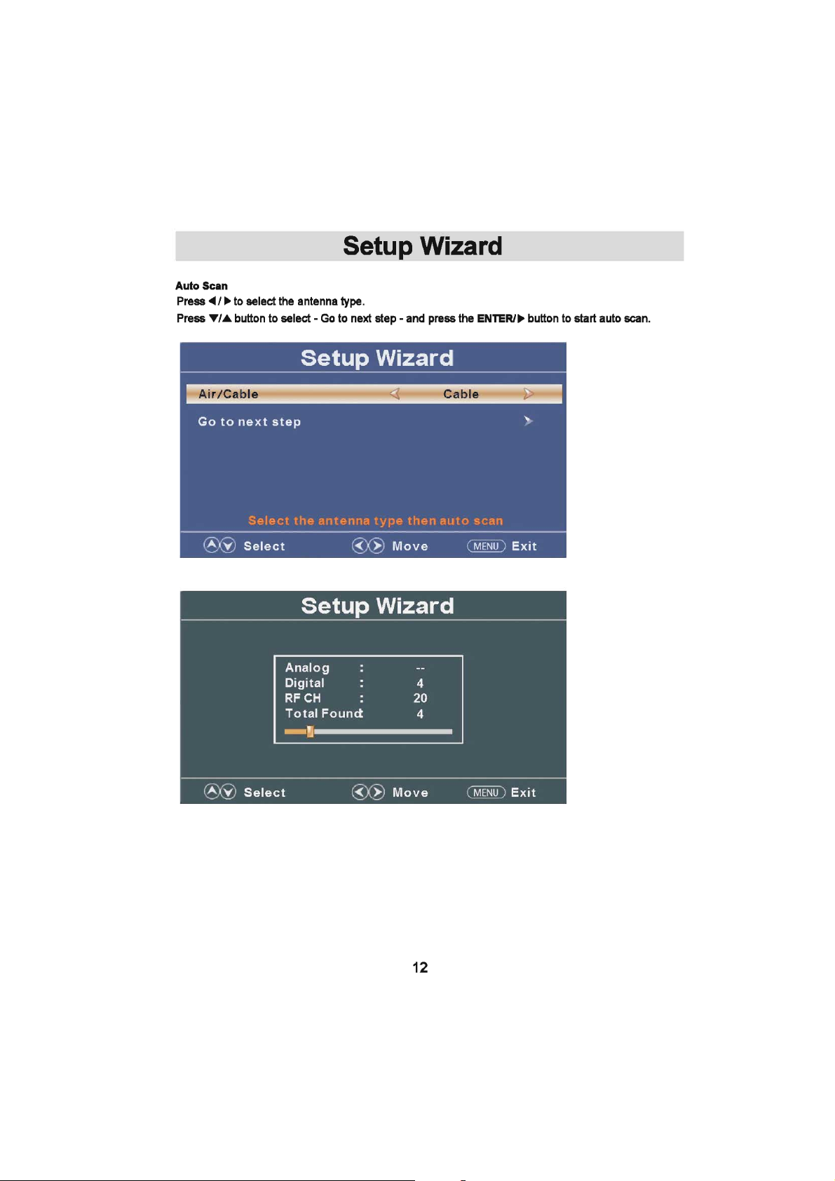
6FDQ DXWRPDWLTXH
Appuyez sur W /X pour sélectionner le type d'antenne.
Appuyez sur la touche S /T pour sélectionner - Aller à l'étape suivante - et appuyez sur la touche/ENTRER
pour démarrer le scan automatique.
12
Page 52

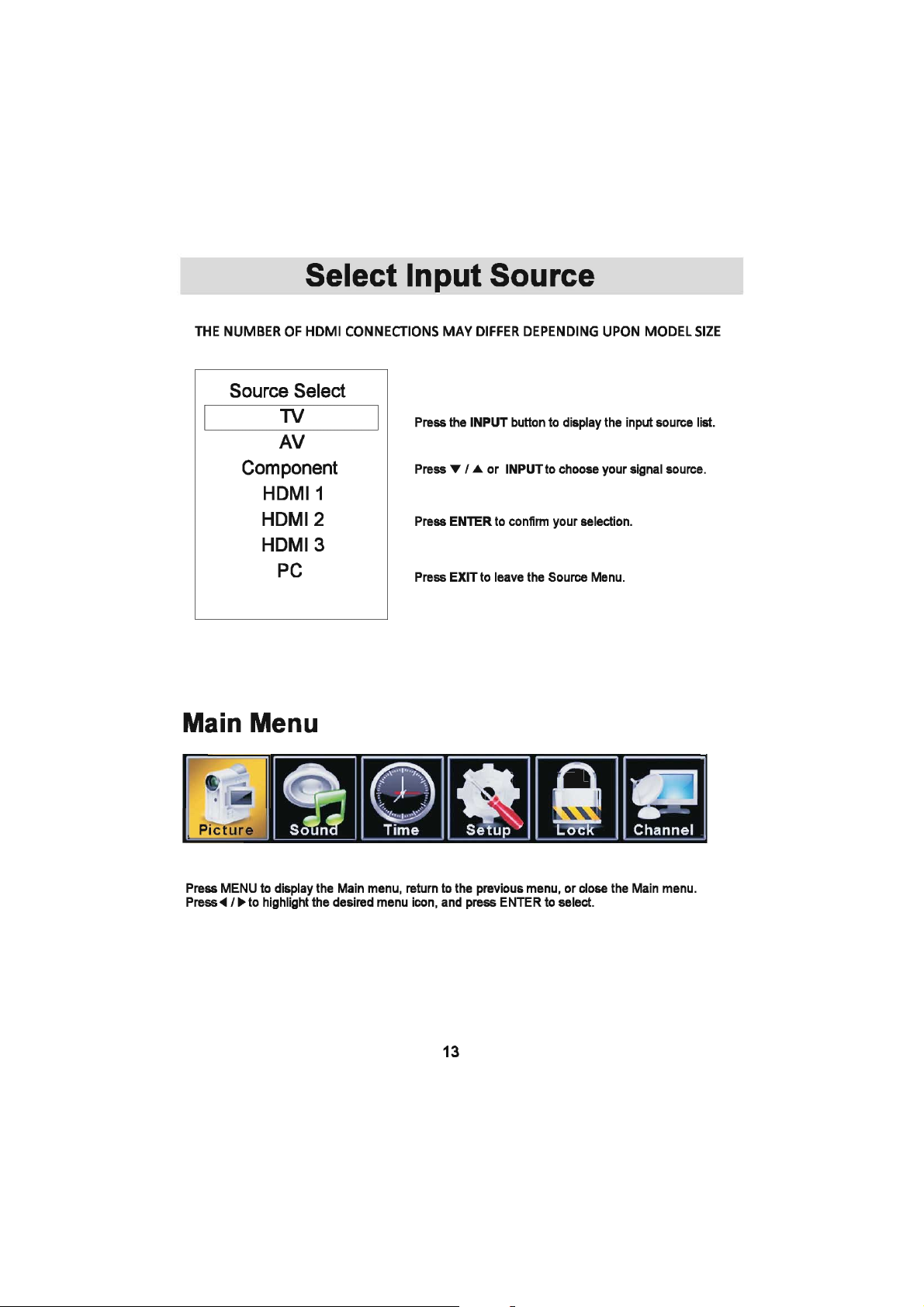
Sélectionner la source d'entrée
> EKDZ KEEy/KE^ ,D/ Whd /&&ZZ ^>KE > d/>> h DK>
Appuyez sur la touche ENTRÉE SRXU DI¿FKHU OD OLVWH GHV
sources d'entrée.
Appuyez sur S /T ou ENTRÉE pour choisir votre source de
signal.
Appuyez sur ENT5(5 SRXU FRQ¿UPHU YRWUH VpOHFWLRQ
Appuyez sur 6257,( pour quitter le menu source.
Menu principal
13
Page 53

TV
Fonctionnement du menu principal
0HQX ,PDJH
Appuyez sur MENU pour entrer dans le menu principal, appuyez sur la touche W /X pour sélectionner.
Appuyez sur ENT5(5/T pour effectuer votre sélection
Appuyez à nouveau sur MENU pour quitter ou retourner au menu principal.
Appuyez sur la touche S /T pour choisir Mode image/Température de couleur/Paramètres avancés.
Appuyez sur ENT5(5 pour sélectionner.
Appuyez sur W /X pour régler.
Appuyez à nouveau sur MENU pour retourner au menu principal.
>0RGH LPDJH@
5pJOH] OH PRGH LPDJH SRXU PRGL¿HU ODSSDUHQFH GH OLPDJH
Appuyez sur la touche W /X pour sélectionner (Standard/Dynamique/Doux/Utilisateur/Économie
d'énergie.
6WDQGDUG 3URGXLW XQH LPDJH KDXWH Gp¿QLWLRQ GDQV XQH SLqFH QRUPDOHPHQW pFODLUpH
'\QDPLTXH 3URGXLW XQH LPDJH KDXWH Gp¿QLWLRQ GDQV XQH SLqFH OXPLQHXVH RX pFODLUpH
'RX[ 3URGXLW XQH LPDJH KDXWH Gp¿QLWLRQ GDQV XQH SLqFH DX[ OXPLqUHV WDPLVpHV
Utilisateur Sélectionnez pour personnaliser les paramètres de l'image.
Le mode économie d'énergie produit un mode de faible consommation d'énergie.
>/XPLQRVLWp@
Réglez la qualité de la perception visuelle de l'image entière ; cela aura une incidence sur la
luminosité de l'image.
Pour effectuer le réglage, appuyez sur la touche W /X.
Remarque : Les ajustements de luminosité, de contraste, de couleur, de teinte et de
netteté sont disponibles uniquement en Mode utilisateur.
>&RQWUDVWH@
Régler l'intensité des écarts de luminosité de l'image, mais l'ombre de l'image est invariable.
Pour effectuer le réglage, appuyez sur la touche W /X.
14
Page 54

TV
>&RXOHXU@
Réglez la saturation de la couleur en fonction de votre préférence.
Pour effectuer le réglage, appuyez sur la touche W /X.
>7HLQWH@
Réglez la teinte (rouge, vert, bleu) de l'image.
Pour effectuer le réglage, appuyez sur la touche W /X.
>1HWWHWp@
Réglez le détail de l'image.
Pour effectuer le réglage, appuyez sur la touche W /X.
>7HPSpUDWXUH GH FRXOHXU@
Augmentez ou réduisez les tons des couleurs chaudes (rouges) et les tons des couleurs froides
(bleus) selon votre préférence.
1RUPDO 6pOHFWLRQ GH FRXOHXU SUpGp¿QLH
Chaud Augmenter la tonalité de couleur rouge.
Froid Augmenter la tonalité de couleur bleue.
>3DUDPqWUHV DYDQFpV@
5pJOH] OHV IRQFWLRQV YLGpR DYDQFpHV SRXU DI¿QHU OLPDJH
Appuyez sur la touche X pour accéder au sous-menu.
>)RUPDW G¶LPDJH@
Normale Ajuste automatiquement Aspect Ratio fonction de la taille et du programme TV TV.
Wide Utilisez l’échelle pour regarder grand écran (16:9) contenu.
Zoom Agrandit l’image pour remplir l’écran. Haut et bas peut être coupé.
Cinéma Étire l’image sur les bords mais en gardant une image claire au centre.
>5pGXFWLRQ GX EUXLW@
'p¿QLU OHV RSWLRQV SRXU UpGXLUH OH EUXLW YLGpR
Off Sélectionnez cette option pour désactiver la détection du bruit vidéo.
Bas Détecter bas et réduire le bruit vidéo bas.
Moyen Détecter et réduire le bruit vidéo modérée.
Haute Détecter et réduire le bruit vidéo améliorée.
Détection automatique Et de réduire le bruit vidéo automatiquement.
15
Page 55

TV
>&RQWUDVWH G\QDPLTXH@
Ajustez automatiquement la netteté et la luminosité de l'image.
Appuyez sur W /X pour sélectionner (Arrêt/Marche)
>0RGH +'0,@
Disponible seulement si vous êtes connecté avec l'entrée HDMI.
Appuyez sur la touche W /X pour sélectionner (Vidéo/Graphique).
Menu Son
Appuyez sur MENU pour entrer dans le Menu principal, Appuyez sur le bouton W /X pour choisir le Son.
Appuyez sur ENTRERź SRXU HQWUHU GDQV OH PHQX
Appuyez sur MENU à nouveau pour sortir ou retourner dans le Menu principal.
Appuyez sur la touche S /T pour choisir le mode d’égaliseur de son / %DVVHV $LJXV %DODQFH / MTS /
Langue audio / Sortie audio numérique / Surround / AVL.
Appuyez sur ENT5(5 źSRXU HQWUHU
Appuyez sur le bouton W / X pour régler.
Appuyez sur MENU pour quitter ou revenir au menu principal.
16
Page 56

TV
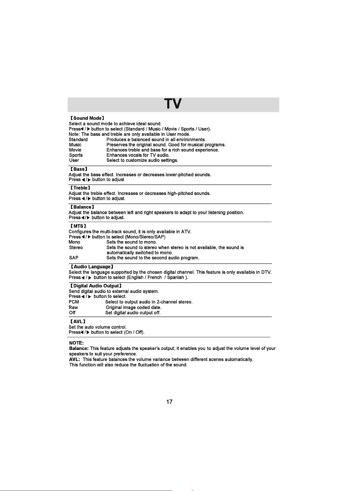
>0RGH DXGLR@
Sélectionnez un mode son pour obtenir le son idéal.
Appuyez sur la touche W /X pour sélectionner (Standard/Musique/Cinéma/Sport/Utilisateur).
Remarque : Les basses et les aigus ne sont disponibles qu’en mode Utilisateur.
Standard Produit un son équilibré dans tous les environnements.
Musique Préserve le son original. Idéal pour les programmes musicaux.
Cinéma Enrichit les aigus et les basses pour une meilleure expérience sonore.
Sports Enrichit les voix pour le son du téléviseur.
Utilisateur Sélectionnez pour personnaliser les paramètres audio.
>%DVVHV@
Réglez l'effet des basses. Augmente ou diminue les sons graves.
Pour régler, appuyez sur la touche W /X
>$LJXV@
Réglez l'effet des aigus. Augmente ou diminue les sons aigus.
Pour effectuer le réglage, appuyez sur la touche W /X.
>%DODQFH@
Réglez la balance entre les haut-parleurs de gauche et de droite pour l'adapter à votre position
d'écoute. Pour effectuer le réglage, appuyez sur la touche W /X.
>076@
&RQ¿JXUH OH VRQ PXOWLSLVWH XQLTXHPHQW GLVSRQLEOH HQ $79
Appuyez sur la touche W /X pour sélectionner (Mono/Stéréo/SAP)
Mono Règle le son en mono.
Stéréo Règle le son en stéréo ; quand la stéréo n'est pas disponible, le son est automatiquement
mis en mono.
SAP Règle le son pour le deuxième programme audio.
>/DQJXH DXGLR@
Sélectionnez la langue compatible avec le canal numérique choisi. Cette fonctionnalité est
uniquement disponible en mode DTV (téléviseur numérique). Appuyez sur la touche W /X pour
sélectionner (anglais/français/espagnol).
>6RUWLH DXGLR QXPpULTXH@
(QYR\H] XQ ÀX[ DXGLR QXPpULTXH j XQ V\VWqPH DXGLR H[WHUQH
Appuyez sur la touche W /X pour sélectionner.
PCM Sélectionnez pour la sortie audio sur le stéréo bicanal.
Fichier RAW Date codée de l’image d’origine.
Off Mettez en marche la sortie audio digitale.
>$9/@
Réglez le contrôle automatique du volume.
Appuyez sur le bouton W /X pour sélectionner (Arrêt/Marche).
REMARQUE :
Balance : Cet élément ajuste la sortie du haut-parleur ; cela vous permet de régler le niveau du
volume de vos enceintes en fonction de vos préférences.
AVL : Cet élément ajuste le volume à des niveaux différents de façon automatique.
&HWWH IRQFWLRQ UpGXLUD pJDOHPHQW OHV ÀXFWXDWLRQV GX VRQ
17
Page 57

TV
0HQX +RUORJH
Appuyez sur MENU pour entrer dans le Menu principal, Appuyez sur le bouton W /X pour choisir l’Heure.
Appuyez sur ENTRERź SRXU HQWUHU
Appuyez sur MENU à nouveau pour sortir ou retournez dans le Menu PRINCIPAL.
Appuyez sur le bouton S /T pour choisir entre Mise en veille/Fuseau horaire/Réglages de l’heure/
Format de l’heure/Horloge Automatique/Horloge.
Appuyez sur ENTRERź SRXU HQWUHU
Appuyez sur le bouton W /X pour ajuster.
Appuyez sur MENU à nouveau pour sortir ou retourner dans le Menu PRINCIPAL.
>0LVH HQ YHLOOH SURJUDPPpH@
Programmez une mise en veille pour que le téléviseur s’éteigne automatiquement.
Appuyez sur le bouton W /X pour choisir (Off/5 min/1O min/15 min/30 min/60 min/90 min/120 min/180
min/240 min).
>)XVHDX KRUDLUH @
Sélectionnez votre fuseau horaire.
Appuyez sur le bouton W /X SRXU FKRLVLU (VW&HQWUH0RQWDJQH3DFL¿TXH$ODVND+DZDw6DPRD7HUUH
Neuve/Atlantique).
>5pJODJHV GH O¶KHXUH DYDQFpH@
Réglez l’heure avancée pour votre zone.
Appuyez sur le bouton W /X pour sélectionner (Arrêt/Marche).
>)RUPDW GH O¶KHXUH@
Choisissez le format de l’heure.
Appuyez sur le bouton W /X pour sélectionner (12-heures/24-heures).
>+RUORJH $XWRPDWLTXH@
Utilisez-la pour synchroniser l’appareil automatiquement. Cette option est seulement disponible sur le DTV
Appuyez sur le bouton W /X pour sélectionner (Arrêt/Marche).
18
Page 58

TV
0HQX 5pJODJHV
Appuyez sur MENU pour entrer dans le Menu principal, Appuyez sur le bouton W /X pour choisir.
Appuyez sur ENTRERź SRXU HQWUHU
Appuyez sur MENU à nouveau pour sortir ou retourner dans le Menu principal.
Appuyez sur le bouton W /X pour choisir entre Langue du Menu/Transparence/Interruption OSD/
Sous-titrage/Surbalayage/Etiquettes d’entrée/Autres Réglages/Restaurer les réglages par défaut/
$VVLVWDQW &RQ¿JXUDWLRQ$SSX\H] VXU (175(5ź SRXU HQWUHU$SSX\H] VXU OH ERXWRQ W /X pour
ajuster.
Appuyez sur MENU à nouveau ou retournez dans le Menu principal.
>/DQJXH GX 0HQX@
&KRLVLVVH] XQH ODQJXH GX PHQX 26' jO¶DI¿FKDJH /¶DQJODLV HVW UpJOp FRPPH ODQJXH GX PHQX SDU
défaut. Appuyez sur le bouton W /X pour choisir la langue (Anglais/Français/Espagnol).
>7UDQVSDUHQFH@
Ajustez la transparence du menu de l’OSD (sur l’écran de l’appareil). Appuyez sur la touche W /X
pour sélectionner. (0 %, 25 %, 50 %, 75 %, 100 %)
>,QWHUUXSWLRQ 26'@
Réglez la durée du menu de l’OSD (sur l’écran de l’appareil).
Appuyez sur le bouton W /X pour choisir (5 s, 15 s, 30 s, 45 s, 60 s).
>6RXVWLWUDJHV@
Réglages pour l’ajustement des Sous-titrages. Seulement disponible sur TV et source AV. Appuyez
VXU OH ERXWRQ (175(5Ź SRXU HQWUHU
Pour plus d’informations merci de bien vouloir vous référer à la page suivante.
19
Page 59

TV
6RXVWLWUDJH
>0RGH 67 @
Mettez le Sous-titrage en mode marche/arrêt.
Appuyez sur le bouton W /X pour choisir ST Off/ST On/ST On/Muet).
>6RXVWLWUDJH DQDORJXH@
Choisissez le Sous-titrage pour le programme standard (analogue).
Appuyez sur le bouton W /X pour choisir ST1/ST2/ST3/ST4/TEXTE 1/TEXTE 2/TEXTE 3/TEXTE 4).
>67 QXPpULTXH @
Choisissez le Sous-titrage pour le programme numérique.
Appuyez sur le bouton W /X SRXU FKRLVLU 2II6HUYLFH 6HUYLFH 6HUYLFH 6HUYLFH 6HUYLFH 6HUYLFH Z
>2SWLRQ@
Ajustez les réglages du Sous-titrage numérique.
$SSX\H] VXU OH ERXWRQ Ź SRXU HQWUHU
>0RGH @
Choisissez l’apparence du Sous-titrage numérique. Utilisations automatiques du style de présentation. Appuyez
sur le bouton W /X pour choisir (Défaut/Personnalisé).
>6W\OH GH OD 3ROLFH@
Choisissez entre 8 styles de police.
Appuyez sur le bouton W /X pour choisir (Défaut/Police 0/Police 1/Police 2/Police 3/Police 4/Police 5/Police 6/
Police 7).
>7DLOOH GH OD 3ROLFH@
Ajustez la taille de la police du Sous-titrage numérique. Appuyez sur le bouton W /X pour choisir (Défaut/Normal/
Grand/Petit).
>6W\OH GH FRQWRXU GH OD 3ROLFH@
Ajustez le contour de la case du Sous-titrage numérique
Appuyez sur le bouton W /X pour choisir (Défaut/Aucun/Relief/Exposant/Homogène/Ombre à gauche/Ombre à
droite).
>6W\OH GH FRXOHXU GH OD 3ROLFH@
Ajustez la couleur de la case du sous-titrage numérique.
Appuyez sur le bouton W /X pour choisir (Défaut/Blanc/Noir/Rouge/Vert/Bleu/Jaune/Magenta/Cyan).
>&RXOHXU GX SUHPLHU SODQ@
Ajustez la couleur de la police du Sous-titrage numérique.
Appuyez sur le bouton W /X pour choisir (Défaut/Blanc/Noir/Rouge/Vert/Bleu/Jaune/Magenta/Cyan).
>&RXOHXU GH O¶DUULqUHSODQ@
Ajustez la couleur de l’arrière-plan du Sous-titrage numérique.
Appuyez sur le bouton W /X pour choisir (Défaut/Blanc/Noir/Rouge/Vert/Bleu/Jaune/Magenta/Cyan).
>2SDFLWp GX SUHPLHU SODQ@
Ajustez la transparence de la police du Sous-titrage numérique.
Appuyez sur le bouton W /X pour choisir (Défaut/Opaque/Brilliant/Translucide).
>2SDFLWp GH O¶DUULqUHSODQ@
Ajustez la transparence de l’arrière-plan du Sous-titrage numérique.
Appuyez sur le bouton W /X
pour choisir (Défaut/Opaque/Brilliant/Translucide).
20
Page 60

TV
>6XUEDOD\DJH@
Appuyez sur le bouton W /X pour sélectionner (Arrêt/Marche).
Il est seulement disponible pour entrer 1080i/720p/1080p en DTV/Composant/interface multimédia
KDXWH Gp¿QLWLRQ ORUVTXH OH 5pJODJH SDU GpIDXW HVW VpOHFWLRQQp 3UpUpJOp VXU 21 HQ $79$9 3UpUpJOp
sur Off en PC/USB.
>eWLTXHWWHV G¶HQWUpH@
Créez des étiquettes pour les appareils connectés à votre TV. Appuyez sur le bouton ENTRERŹ
pour entrer.
>$XWUHV UpJODJHV@
Réglez les paramètres audio uniquement. Appuyez sur le bouton ENTRERŹ SRXU HQWUHU
>eFUDQ EOHX@
Pour choisir le type de transition souhaité tout en passant d’une chaîne à l’autre.
Appuyez sur le bouton W /X pour sélectionner (Arrêt/Marche).
>$XGLR 8QLTXHPHQW@
Diffusez du son avec l’image éteinte. Lorsque vous mettez uniquement en marche le son et sortez du
PHQX 26' OH SDQQHDX GH FRQ¿JXUDWLRQ VHUD QRLU j FH PRPHQW DSSX\H] VXU Q¶LPSRUWH TXHOOH WRXFKH
pour sortir du mode Audio Uniquement.
Appuyez sur le bouton W /X pour sélectionner (Arrêt/Marche).
21
Page 61

TV
>5HVWDXUDWLRQ SDU GpIDXW@
0RGL¿H] OHV RSWLRQV HQ FRXUV RX UHGpPDUUHU OD 79 SRXU UHVWDXUHU OHV SDUDPqWUHV SDU GpIDXW
Appuyez sur le bouton ENTRERŹ SRXU HQWUHU
>$VVLVWDQW GH FRQ¿JXUDWLRQ@
Revenir à l’installation d’origine
Appuyez sur le bouton ENTRERŹ SRXU HQWUHU
Pour plus de détails merci de vous référer aux instructions du Menu réglages, page 11
22
Page 62

TV
0HQX 9HUURXLOODJH
Appuyez sur MENU pour entrer dans le menu principal, Appuyez sur le bouton W /X pour
sélectionner.
Appuyez sur ENTRERź SRXU HQWUHU
Appuyez sur MENU à nouveau pour sortir ou retourner dans le Menu principal.
Appuyez sur le bouton S /T pour choisir Changement du mot de passe/Blocage du Système/Bloc
G¶HQWUpH&ODVVL¿FDWLRQ DPpULFDLQH&ODVVL¿FDWLRQ FDQDGLHQQH5pJODJHV 5575HGpPDUUDJHGX557
Menu hôtel
Appuyez sur ENTRERź SRXU HQWUHU
Appuyez sur le bouton W /X pour ajuster.
Appuyez sur MENU à nouveau ou retournez au menu principal.
Saisissez votre mot de passe à 4 chiffres. Le mot de passe par défaut est 0000 et en cas d’oublie de
votre mot de passe, veuillez appeler notre Service Client au 1-800-289-0980 pour obtenir de l’aide.
23
Page 63

TV
>&KDQJH] GH PRW GH SDVVH@
6DLVLU XQ QRXYHDX PRW GH SDVVH j FKLIIUHV SXLV OH VDLVLU j QRXYHDX SRXU OH FRQ¿UPHU
$SSX\H] VXU OH ERXWRQ Ź SRXU HQWUHU
>%ORFDJH GX 6\VWqPH@
Bloquez ou débloquez les boutons sur la TV. Appuyez sur le bouton W /X pour choisir (Off/On).
>%ORF G¶HQWUpH@
Bloquez ou débloquez les sources d’entrée.
$SSX\H] VXU OH ERXWRQ Ź SRXU HQWUHU
Appuyez sur le bouton W /X pour choisir (Débloquer/Bloquer).
>&ODVVL¿FDWLRQ DPpULFDLQH@
)LOPV HW SURJUDPPHV 79 OLPLWpV SDU OD &ODVVL¿FDWLRQ DPpULFDLQH'LVSRQLEOHV XQLTXHPHQW ORUVTXH ©
%ORFDJHV\VWqPH ª HVW VXU © PDUFKH ª $SSX\H] VXU OH ERXWRQ Ź SRXU HQWUHU
Pour les détails merci de vous référer aux pages 25-26
>5pJODJHV 577@
$I¿FKH XQ WDEOHDX GH FODVVL¿FDWLRQ DYDQFp GH FDUWH j SXFH DQWLYLROHQFH SRXU OHV FKDvQHV QXPpULTXHV
&HW pOpPHQW HVW XQLTXHPHQW GLVSRQLEOH ORUVTXH OH FRXUDQW GLVSRVH GH GRQQpHV GH FODVVL¿FDWLRQ
téléchargeables.
>5HGpPDUUDJH 557@
Redémarrez le RTT par défaut.
&HW pOpPHQW HVW XQLTXHPHQW GLVSRQLEOH ORUVTXH OH FRXUDQW GLVSRVH GH GRQQpHV GH FODVVL¿FDWLRQ
téléchargeables.
>0HQX +{WHO@
$SSX\H] VXU OH ERXWRQ Ź SRXU HQWUHU
Pour plus de détails merci de vous référer à la page 27.
24
Page 64

TV
&ODVVL¿FDWLRQ DPpULFDLQH
3RXU OHV eWDWV8QLV OHV SDUDPqWUHV GH FODVVL¿FDWLRQ LQFOXHQW OHV RSWLRQV VXLYDQWHV 79 03$$
TV
/D FODVVL¿FDWLRQ WpOpYLVXHOOH HVW EDVpH VXU GHX[ FULWqUHV O¶kJH HW OH FRQWHQX
ÆJH 'p¿QLU
TV-Y Tout âge
TV-Y7 7 ans et plus
TV-G Grand public
TV-PG (Parental guidance) Contrôle parental
TV-14 14 ans et plus
TV-MA 17 ans et plus
* Remarque :
/HV FODVVL¿FDWLRQV GH FRQWHQX DXJPHQWHURQW HQ IRQFWLRQ GX QLYHDX GH OD FODVVL¿FDWLRQ EDVpH VXU O¶kJH
3DU H[HPSOH XQ SURJUDPPH DYHF XQH FODVVL¿FDWLRQ 793* 9 YLROHQFH SHXW FRQWHQLU XQH YLROHQFH PRGpUpH WDQGLV
TX¶XQH FODVVL¿FDWLRQ 79 9 YLROHQFH SHXW FRQWHQLU XQH YLROHQFH LQWHQVH$LQVL EORTXHU XQH RSWLRQ G¶XQ QLYHDX
plus élevé débloquera automatiquement des options qui possèdent des niveaux plus sensibles.
25
Page 65

TV
MPAA
Ce système Gp¿QLW le contrôle GH FODVVL¿FDWLRQ qui au regard des règles du MPAA.
&ODVVL¿FDWLRQ 'p¿QLU
G Grand public. Tout âge.
PG
PG-13
R
NC-17 Interdit aux moins de 17 ans.
X Uniquement pour un public adulte.
Off 3DV GH FODVVL¿FDWLRQ pWDEOLH
Contrôle parental recommandé. Certains contenus sont susceptibles
ne pas être adaptés aux enfants
Parents fortement mis en garde. Certains contenus peuvent être
inappropriés pour les enfants de moins de 13 ans.
Restreint. Les enfants de moins de 17 ans doivent être
accompagnés d’un parent ou d’un adulte.
26
Page 66

Menu Hôtel
TV
>0RGH +{WHO@
Mettre le mode hôtel sur Marche ou Arrêt.
Remarque : Les réglages suivants fonctionnent seulement lorsque le mode hôtel est prévu pour être
en Marche.
>5pJODJHV GH O¶LQLWLDOLVDWLRQ@
>0RGH LPDJH@
5pJOH] OH PRGH LPDJH SRXU PRGL¿HU ODSSDUHQFH GH OLPDJH
Appuyez sur le bouton W /X pour choisir (Standard/Dynamique/Léger/Utilisateur).
>9ROXPH SDU GpIDXW@
Réglez le volume par défaut chaque fois que vous allumez la TV, le volume par défaut est à 20.
Volume 0D[@
Réglez le volume maximal en fonction de comment vous pouvez l’ajuster.
>6RXUFH GH GpPDUUDJH@
Réglez la source d’entrée par défaut lorsque vous mettez en marche votre TV.
27
Page 67

TV
>&DQDO GH GpPDUUDJH@
Réglez le canal de démarrage sur Marche ou Arrêt.
Remarque : Le choix du canal est disponible lorsque le Démarrage du canal est réglé sur Marche.
>&KRL[ GX FDQDO@
5pJOH] OH GpPDUUDJH SDU GpIDXW VXU OH FDQDO FKRLVL OD PRGL¿FDWLRQ GH OD UHFKHUFKH GH FDQDO D pWp
effectuée.
>%ORFDJH K{WHO@
Pour bloquer le Tuner/Clavier/Menu mettre le Blocage du Tuner sur Marche.
La recherche de chaînes n’est pas valide lorsque le Blocage du Tuner est sur Marche.
>eFRQRPLH G¶pQHUJLH@
Réglez le programmateur du TV de sorte qu’il s’éteigne automatiquement.
Programmations possibles : 60 min 120 min, 180 min, 240 min, Arrêt
>79 j 86%@
Sauvegardez les donnés sur l’USB.
>86% j 79@
Restaurez les données depuis l’USB.
>5HGpPDUUDJH GHV 5pJODJHV +{WHO @
Récupérez les réglages par défaut du menu Hôtel.
28
Page 68

TV
0HQX GHV FKDvQHV
Appuyez sur MENU pour entrer dans le Menu principal, Appuyez sur W /X
$SSX\H] VXU (175(5ź SRXU DFFpGHU W /X au bouton de sélection.
Appuyez sur MENU à nouveau pour sortir ou retourner dans le Menu principal.
$SSX\H] VXU OH ERXWRQ źŸ SRXU VpOHFWLRQQHU $LU&DEOH$XWR 6FDQ)DYRULV/LVWH GH FKDvQHV0RQWUHU
Cacher/Numéro de chaîne/Étiquette de chaîne.
$SSX\H] VXU (175(5ź SRXU HQWUHU
Pour effectuer le réglage, appuyez sur la touche W /X.
Appuyez sur MENU à nouveau ou retournez dans le Menu principal.
>$LU&DEOH@
Choisir le type de signal.
Appuyez sur le bouton W /X pour choisir (Air/Cable).
>$XWR 6FDQ@
Recherche automatique de chaînes.
Appuyez sur le bouton ENTREE IV pour entrer.
29
Page 69

TV
>)DYRULV@
$MRXWH] GHV FKDvQHV SRXU FUpHU XQH OLVWH GH IDYRULV$SSX\H] VXU OH ERXWRQ Ź SRXU HQWUHU
>/LVWH GH FKDvQHV@
$I¿FKH YRWUH OLVWH GH SURJUDPPHV$SSX\H] VXU OH ERXWRQ Ź SRXU HQWUHU
>0RQWUHU&DFKHU@
0RQWUH] RX FDFKH] OHV FKDvQHV GH YRWUH OLVWH GH SURJUDPPHV$SSX\H] VXU OH ERXWRQ Ź SRXU HQWUHU
>1XPpUR GH FKDvQH@
Montrez le numéro de chaîne. Pour effectuer le réglage, appuyez sur la touche W /X.
>eWLTXHWWH GH FKDvQH@
Créez des étiquettes pour les chaînes, jusqu’à 7 caractères. Pour effectuer le réglage, appuyez sur la
touche W /X.
30
Page 70

PC
Menu PC
Appuyez sur SORTIE pour choisir la source PC.
Appuyez sur MENU pour entrer dans le menu Principal, Appuyez sur le bouton W /X pour choisir le
menu Réglages.
$SSX\H] VXU ź SRXU VpOHFWLRQQHU OHV 5pJODJHV 3&
$SSX\H] VXU OH ERXWRQ źŸ SRXU FKRLVLU +3RV93RV+RUORJH3KDVH$XWR
Appuyez sur ENTRERź SRXU HQWUHU
Appuyez sur le bouton W /X pour ajuster.
Appuyez sur le bouton MENU à nouveau ou retournez au menu Principal.
31
Page 71

PC
>+3RV@
Ajustez la position horizontale de l’image. Appuyez sur le bouton W /X pour ajuster.
>93RV@
Ajustez la position verticale de l’image. Appuyez sur le bouton W /X pour ajuster.
>+RUORJH@
Ajustez les lignes verticales qui interfèrent. W /X
>3KDVH@
Ajustez les lignes horizontales qui interfèrent. Appuyez sur le bouton W /X pour ajuster.
>$XWR@
Ajustez l’écran automatiquement jusqu’à la position optimale de l’image.
$SSX\H] VXU OH ERXWRQ Ź SRXU HQWUHU 9RXV GHYH] DSSX\HU VXU OH ERXWRQ $872 GH OD WpOpFRPPDQGH
* Remarque :
1. La couleur, la teinte, la nuance, la réduction du bruit, le contraste dynamique et le
Mode HDMI de IMAGE ne sont pas valides.
2. Le MTS et le Langage Audio dans le menu SON ne sont pas valides.
3. L’horloge automatique dans le menu HEURE n’est pas valide.
4. Le sous-titrage dans le menu RÉGLAGES est invalide.
5. /D FODVVL¿FDWLRQ DPpULFDLQH OD FODVVL¿FDWLRQ FDQDGLHQQH OHV UpJODJHV 557 HW OH
redémarrage RRT dans le menu BLOCAGE ne sont pas valides.
6. Le mode PC n’a pas de menu CHAÎNE.
32
Page 72

Aide
Pas de courant
Pas de réception correcte du signal
Pas d’image
Mauvaise qualité du son ou pas
de son
9pUL¿H] TXH OH FkEOH G¶DOLPHQWDWLRQ $& GH OD WpOpYLVLRQ HVW FRUUHFWHPHQW EUDQFKp GDQV OD
prise. S’il n’y a toujours pas de courant, retirez le câble d’alimentation AC et rebranchez-le
après 60 secondes. Essayez de démarrer à nouveau la télévision.
t Une image double ou fantôme peut être provoquée par des obstructions de l’antenne
externe. Consultez le mode d’emploi pour changer la direction de l’antenne externe.
Peut-être que la localisation de l’antenne n’est pas bonne. L’utilisation d’une antenne
plus haute peut améliorer la qualité des images.
6L YRXV XWLOLVH] XQH DQWHQQH j O¶LQWpULHXU OD UpFHSWLRQ SHXW rWUH GLI¿FLOH GDQV FHUWDLQV
cas. Vous pouvez essayer d’ajuster l’antenne d’intérieur pour améliorer l’image. Si cela
n’améliore pas l’image, l’antenne extérieure aura besoin d’être ajustée.
t Assurez-vous que l’antenne située derrière l’appareil est correctement connectée.
Essayez de sélectionner d’autres chaînes pour être sûr que le problème ne vient pas de
la chaîne.
9pUL¿H] V¶LO Q¶\ D SDV G¶DXWUHV VRXUFHV G¶LQWHUIpUHQFH
Augmentez le volume.
Assurez-vous que l’appareil n’est pas en mode MUET. Appuyez sur le bouton muet pour
restaurer le son.
Essayez de sélectionner d’autres chaînes pour être sûr que le problème ne vient pas de
la chaîne.
9pUL¿H] V¶LO Q¶\ D SDV G¶DXWUHV VRXUFHV G¶LQWHUIpUHQFH
Assurez-vous que l’antenne située derrière l’appareil est correctement connectée.
Ajustez les contrastes et/ou la luminosité du TV.
Couleur de mauvaise qualité ou pas
de couleur
Mauvaise réception 9pUL¿H] SRXU rWUH VU TXH O¶DQWHQQH VLWXpH GHUULqUH O¶DSSDUHLO HVW FRUUHFWHPHQW FRQQHFWpH
Lignes horizontales ou diagonales
sur l’écran.
Le TV ne répond pas à la télécommande
Pas de vidéo en mode PC
L’écran est trop sombre ou trop clair
en mode PC.
Pas de réponse en mode PC 9pUL¿H] TXH OHV UpJODJHV GH O¶RUGLQDWHXU VRQW FRPSDWLEOHV DYHF OHV UpVROXWLRQV GH O¶DSSDUHLO
Lignes sur l’image pendant l’utilisation
de la connexion RCA
Essayez de sélectionner d’autres chaînes pour être sûr que le problème ne vient pas de
la chaîne.
Assurez-vous que l’antenne située derrière l’appareil est correctement connectée.
L’appareil peut subir des interférences d’autres appareils tels qu’un sèche cheveux ou un
aspirateur. Cessez l’usage de ces appareils pour améliorer la réception.
Assurez-vous que l’antenne située derrière l’appareil est correctement connectée.
Pointez la télécommande directement sur le détecteur du TV. Si cela ne marche pas, veillez
à ce que la télécommande est en état de marche (piles positionnées correctement, etc.)
9pUL¿H] TXH OH FkEOH GH O¶DSSDUHLO HVW FRUUHFWHPHQW FRQQHFWp j OD VRUWLH 9*$
9pUL¿H] TXH OH FkEOH GH O¶DSSDUHLO Q¶HVW SDV SOLp RX HQGRPPDJp
Ajustez le rapport contraste ou luminosité dans le Menu principal.
9pUL¿H] TXH OH FkEOH HVW FRUUHFWHPHQW FRQQHFWp j OD VRUWLH
9pUL¿H] TXH OH FkEOH Q¶HVW SDV SOLp RX HQGRPPDJp
Utilisez un câble RCA correct.
Les problèmes persistent
Débranchez le câble d’alimentation et attendez 60 secondes, puis rebranchez-le. Si le
problème persiste avec l’appareil, merci de ne pas essayer de le réparer par vous même.
Contactez le Service Client pour obtenir de l’assistance.
33
Page 73

Caractéristiques
Taille de l’écran Chaînes pré-programmées Sortie d’enceintes
techniques
24” NT
28” NT
32” NT
39” NT
42” NT
50” NT
Taille de l’écran
SC:AIR 2-69 CÂBLE 1-125
SC:AIR 2-69 CÂBLE 1-125
SC:AIR 2-69 CÂBLE 1-125
SC:AIR 2-69 CÂBLE 1-125
SC:AIR 2-69 CÂBLE 1-125
SC:AIR 2-69 CÂBLE 1-125
Mise en marche
Consommation (LED)
5W + 5W
8W + 8W
10W + 10W
10W + 10W
10W + 10W
10W + 10W
Accessoires
24” 31 W
28” 31 W
32” 51
39” 76
42” 67 W
50”
W
W
108 W
Notice d’utilisation des Piles AAA de la
télécommande
34
Page 74

Télécommande
1. Mise en marche:
2. MUET: Appuyez pour mettre en mode muet. Appuyez à nouveau ou
appuyez sur VOL+ pour désactiver le mode muet.
3. 0-9 : Appuyez de 0-9 pour choisir une chaîne TV lorsque vous regar-
dez la TV. La chaîne changera après quelques secondes.
4. - : Appuyez sur “-” pour entrer un numéro de programme pour une
chaîne à multiples programmes, tel que 2-1 etc. Revenir à la
chaîne précédemment visionnée.
5. : Revenir à la chaîne précédemment visionnée.
6. 02'( 3
7. VEILLE: Choisissez la période de temps avant que la TV ne
8. 02'( 9: Appuyez pour naviguer entre les différents réglages
9. MENU: Vous permet de naviguer dans les menus à l’écran.
10. SOURCE: Ajustez pour naviguer entre les sources de sortie
Réglez votre TV pour qu’elle s’allume ou se mette en
mode veille.
: Appuyez pour naviguer entre les différents réglages
d’image.
s’éteigne automatiquement.
du son.
comme suit : TV → AV ൺ YPBPR ൺ HDMI1 ൺ
HDMI2 ൺ HDMI3 ൺ PC
10
15
11
. STICK ANALOGIQUE ( / / / /ENTRER):
Vous permet de naviguer dans les menus à l’écran et d’ajuster
les réglages du système à vos préférences.
12. SORTIE:
13. AFFICHAGE: $SSX\H] SRXU DI¿FKHU OD VRXUFH HW OHV LQIRUPD-
14. MTS: Appuyez pour choisir le mode audio, vous pouvez
15. V +/-: Appuyez pour augmenter ou diminuer le niveau du
16. CH +/-: Appuyez pour naviguer ou sélectionner une chaîne.
17. AUTO: Ajuste le niveau de l’image du PC automatiquement.
18. FAV: Réglez ou annulez votre chaîne en cours pour en faire
19. FAV +: Descendez jusqu’à votre programme Favori.
20. FAV -: Montez jusqu’à votre programme Favori.
21. ST $SSX\H] SRXU DI¿FKHU OH VRXVWLWUDJH
Sortez du menu ou du sous-menu et annulez la
fonction en cours (si possible).
tions de la chaîne.
choisir Stereo, Mono, ou SAP (programme secondaire audio).
son.
votre chaîne favorite.
22. ZOOM&KRLVLVVH] OH PRGH DI¿
FKDJH
35
Page 75

GARANTIE
limitée
ORION garantit ce produit contre tout défaut de fabrication, de matériau et de manufacture dans des
conditions normales d’utilisation pour une période de 1 an à compter de la date originale d’achat aux États-Unis.
Si un service doit être effectué dans le cadre de cette garantie pour une quelconque raison due à un défaut
de fabrication ou de dysfonctionnement durant la première période de 12 mois à partir de la date originale d’achat,
ORION fournira un service en retour atelier pour les unités dont la taille de l’écran est égale ou inférieure à 40 pouces,
et en service à domicile pour les unités dont la taille de l’écran est égale ou supérieure à 42 pouces uniquement par
un Centre de Service Indépendant autorisé par ORION sans frais supplémentaires. En outre, si une pièce d’origine
se détériore en raison d’un défaut de fabrication de matériel ou de main-d’œuvre pendant un an à compter de la date
originale d’achat, nous remplacerons la pièce défectueuse , étant entendu que le défaut ou le dysfonctionnement est
YpUL¿p HW TXH OD SUHXYH GH GDWH G¶DFKDW HVW IRXUQLH
Il existe des Centres de Services Indépendants autorisés par ORION situés dans tout le pays. Pour contacter
celui le plus proche de chez vous , APPELEZ LE NUMERO GRATUIT : 1-800-289-0980 ou visitez notre Site
,QWHUQHW VXU ZZZRULRQVDOHVLQFFRP 25,21 QH VHUD SDV WHQX UHVSRQVDEOH GHV GRPPDJHV VXELV SDU OH WUDQVSRUW
de l’appareil. S’il n’y a pas Centres de Services Indépendants autorisés par ORION dans votre zone veuillez appeler le - 1-800-289-0980 pour obtenir de l’assistance.
Remarque : Cette garantie est nulle si le produit est :
(a) Endommagé en raison d’une négligence, un mauvais usage, un abus, ou un accident.
(b) Utilisé dans un cadre commercial ou une location.
F 0RGL¿p RX UpSDUp SDU TXLFRQTXH DXWUH TX¶XQ &HQWUH GH 6HUYLFH DXWRULVp SDU 25,21 SRXU HIIHFWXHU des répara-
tions de garantie de la classe de produit ou par le Centre de Service d’Usine d’ORION.
(d) Endommagé car il a été improprement connecté à l’appareil d’autres fabricants.
Cette garantie ne couvre pas :
(a) Les dommages que pourraient subir les équipements mal connectés au produit.
(b) Les coûts encourus lors du transport du produit vers un Centre de Services autorisé par ORION ou
un Centre de Service d’Usine d’ORION.
(c) Les dommages ou une opération impropre de l’appareil causée par un abus du client, un mauvais usage, une
négligence, ou un manque consécutif à des instructions d’opérations fournies avec le produit.
(d) Les ajustements ordinaires du produit qui peuvent être réalisés par le client comme souligné dans le manuel du
propriétaire. manual.
(e) Les problèmes de réception du signal causés par une antenne externe ou des systèmes de câble.
CETTE GARANTIE N’EST PAS TRANSFERABLE ET S’APPLIQUE SEULEMENT À L’ACHETEUR D’ORIGINE
ET NE S’ÉTEND PAS À DES PROPRIÉTAIRES SUBSEQUENTS DU PRODUIT. TOUTE GARANTIE APPLICABLE,
Y COMPRIS LA GARANTIE DE COMMERCIALISATION, EST LIMITÉE DANS LE TEMPS À UNE PÉRIODE DE
GARANTIE EXPRESS COMME FOURNIE DANS LA PRÉSENTE À COMPTER DE LA DATE D’ACHAT ORIGINALE AU DÉTAIL ET AUCUNE GARANTIE, QUELLE SOIT EXPRESS OU IMPLICITE NE DOIT S’APPLIQUER AU
PRODUIT CI-APRÈS. ORION NE GARANTIT PAS LES APTITUDES DU PRODUIT POUR TOUTE UTILISATION
PARTICULIÈRE.
EN AUCUN CAS ORION NE POURRAIT ÊTRE TENU RESPONSABLE POUR TOUTE PERTE, DIRECTE
OU INDIRECTE, TOUT INCIDENT, SPÉCIAL OU UN DOMMAGE CONSÉQUENT SURGISSANT DE OU EN
CONNEXION AVEC L’UTILISATION DE CE PRODUIT.
CETTE GARANTIE EST UNIQUEMENT VALABLE AUX ÉTATS UNIS D’AMÉRIQUE. CETTE GARANTIE VOUS
DONNE DES DROITS LÉGAUX SPÉCIFIQUES, CEPENDANT, VOUS POUVEZ AVOIR D’AUTRES DROITS QUI
POURRAIENT VARIER D’UN ÉTAT À L’AUTRE. CERTAINS ÉTATS NE PERMETTENT PAS DE LIMITE DE DURÉE
SUR LES GARANTIES IMPLICITES OU D’EXCLUSION DE DOMMAGES CONSÉQUENTS AINSI CES RESTRICTIONS PEUVENT NE PAS S’APPLIQUER À VOUS.
25,21 6$/(6 ,1&
3471 N. UNION DR.
OLNEY, ILLINOIS 62450
 Loading...