

Page 1
OWNER’S MANUAL
MANUAL DE INSTRUCCIONES
19" WIDE TFT LCD TELEVISION WITH DIGITAL TUNER
TELEVISOR LCD TFT DE 19" CON SINTONIZADOR DIGITAL
HDLCD1955
HDLCD1955A
ATTENTION
If you purchase a universal remote control from your local retailer, please contact the remote manufacturer for the required programming code.
Si usted a comprado un control de remoto universal, por favor comunicase con el fabricante para el
código de programación requerido.
ATENCION
ESPAÑOL ENGLISH
AIR/CABLE MODE SELECTION
When shipped from the factory, the Signal Type option is set to the “Cable” (Cable Television) mode. If
not using Cable TV, set this menu option to the “Air” position.
Al salir la unidad de fábrica, la opción Signal Type se ajusta al modo de “Cable” (Televisión por cable).
Si no utiliza CATV, ajuste esta opción de menú al modo de “Air”.
SI REQUIERE CONTACTAR SERVICIO AL CLIENTE POR FAVOR TENGA EL NÚMERO DE
PLEASE HAVE THE MODEL NUMBER READY PRIOR TO THE CALL
SELECCION DE MODO DE AIR/CABLE
IF CONTACT WITH CUSTOMER SERVICE IS REQUIRED
MODELO LISTO ANTES LLAMAR
CUSTOMER SERVICE – 1-800-289-0980
SERVICIO AL CLIENTE – 1-800-289-0980
ORION WEBSITE
SITIO WEB DE ORION
FOR INFORMATION ON OUR OTHER PRODUCTS AND RECYCLING INFORMATION, PLEASE VISIT OUR WEBSITE AT
PARA INFORMACIÓN SOBRE OTROS PRODUCTOS E INFORMACIÓN SOBRE RECICLAJE,
POR FAVOR VISITE NUESTRO SITIO WEB EN
www.orionsalesinc.com
Before operating the unit, please read this manual thoroughly.
Antes de usar la unidad, lea detenidamente este manual de instrucciones.
Page 2
ENGLISH
The lightning flash with arrowhead
symbol, within an equilateral triangle
is intended to alert the user to the
presence of uninsulated dangerous
voltage within the product's enclosure
that may be of sufficient magnitude to
constitute a risk of electric shock.
CAUTION: TO REDUCE THE RISK OF ELECTRIC
SHOCK, DO NOT REMOVE COVER
(OR BACK). NO USER-SERVICEABLE
PARTS INSIDE. REFER SERVICING TO
QUALIFIED SERVICE PERSONNEL.
The exclamation point within an
equilateral triangle is intended to
alert the user to the presence of
important operating and maintenance
(servicing) instructions in the literature
accompanying the appliance.
WARNING: TO PREVENT FIRE OR SHOCK HAZARD, DO NOT EXPOSE THIS APPLIANCE TO RAIN
OR MOISTURE.
TO PREVENT THE SPREAD OF FIRE, KEEP CANDLES OR OPEN FLAMES AWAY
FROM THIS PRODUCT AT TIMES.
CAUTION: TO PREVENT ELECTRIC SHOCK DO NOT USE THIS POLARIZED PLUG WITH AN
EXTENSION CORD, RECEPTACLE OR OTHER OUTLET UNLESS THE BLADES CAN BE
FULLY INSERTED TO PREVENT BLADE EXPOSURE.
WARNING: This equipment has been tested and found to comply with the limits for a Class B digital device,
However, there is no guarantee that interference will not occur in a particular installation. If
CAUTION: Changes or modifications not expressly approved by the party responsible for compliance with the
The lamp(s) within this product contain mercury.
Disposal should be in compliance with local, state or
federal laws.
pursuant to Part 15 of the FCC Rules. These limits are designed to provide reasonable protection
against harmful interference in a residential installation. This equipment generates, uses and can
radiate radio frequency energy and, if not installed and used in accordance with the instructions,
may cause harmful interference to radio communications.
this equipment does cause harmful interference to radio or television reception, which can be
determined by turning the equipment off and on, the user is encouraged to try to correct the
interference by one or more of the following measures:
- Reorient or relocate the receiving antenna.
- Increase the separation between the equipment and receiver.
-
Connect the equipment into an outlet on a circuit different from that to which the receiver is connected.
- Consult the dealer or an experienced radio/TV technician for help.
FCC Rules could void the user's authority to operate this equipment.
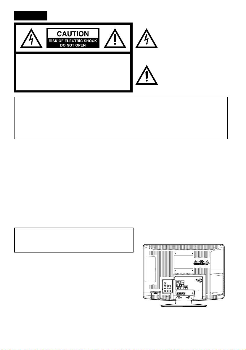
Location of the required Marking
The rating sheet and the safety caution are
on the rear of the unit.
Record the model number and serial number.
Model number _______________ Serial number _______________
2
Page 3
15) Apparatus should not be exposed to dripping or splashing, and objects filled with liquids, such as
vases, should not be placed on the apparatus.
16) An outside antenna system should not be located in the vicinity of overhead power lines or other
electric light or power circuits, or where it can fall into such power lines or circuits. When installing an
outside antenna system, extreme care should be taken to keep from touching such power lines or
circuits, as contact with them might be fatal.
17) Do not overload wall outlets and extension cords, as this can result in a risk of fire or electric shock.
18) Do not push objects through any openings in this unit, as they may touch dangerous voltage points
or short out parts that could result in fire or electric shock. Never spill or spray any type of liquid into
the unit.
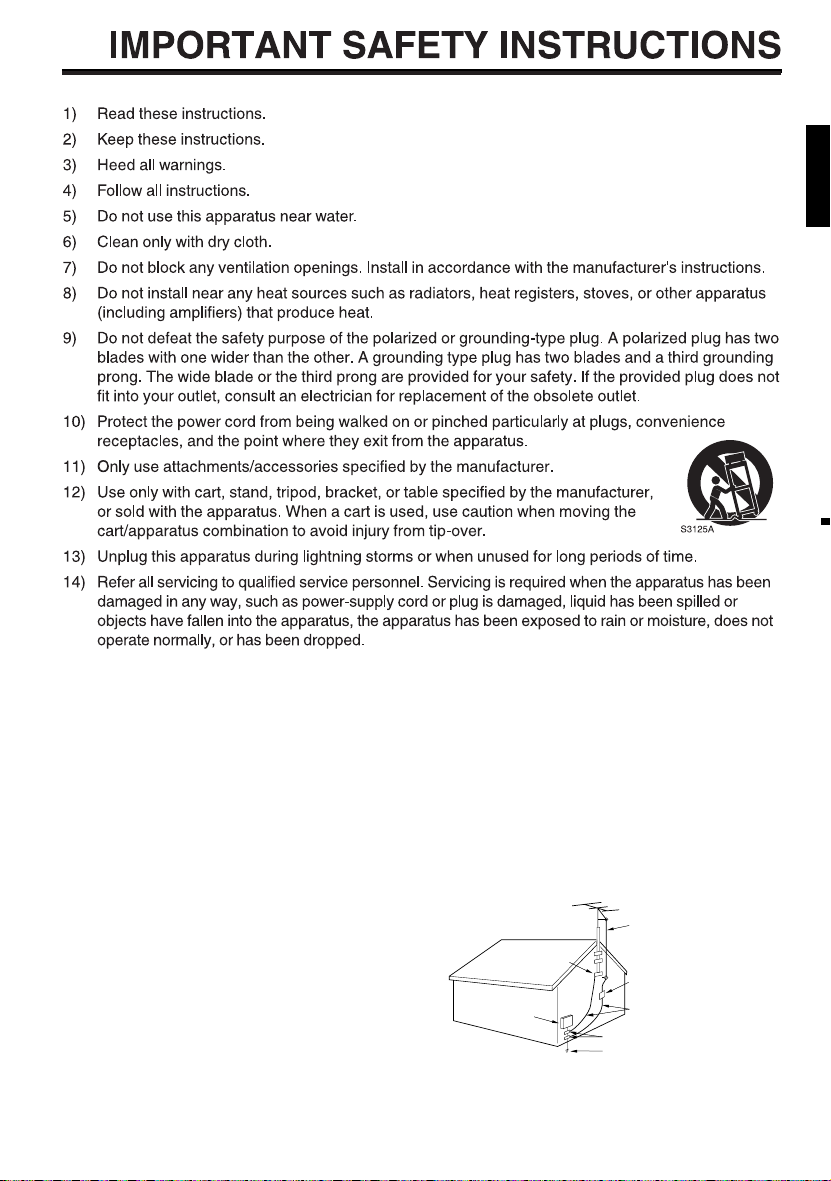
19) If an outside antenna or cable system
EXAMPLE OF ANTENNA GROUNDING AS PER THE NATIONAL ELECTRICAL CODE
is connected to the unit, be sure the
antenna or cable system is grounded
to provide some protection against
voltage surges and built-up static
charges, Section 810 of the National
Electrical Code, ANSI/NFPA 70, provides
information with respect to proper
grounding of the mast and supporting
structure, grounding of the lead-in
wire to an antenna discharge unit, size
of grounding conductors, location of
GROUND
ELECTRIC SERVICE
EQUIPMENT
NEC-NATIONAL ELECTRICAL CODE
S2898A
CLAMP
ANTENNA LEAD IN WIRE
ANTENNA
DISCHARGE UNIT
(NEC SECTION 810-20)
GROUNDING CONDUCTORS
(NEC SECTION 810-21)
GROUND CLAMPS
POWER SERVICE GROUNDING
ELECTRODE SYSTEM
(NEC ART 250, PART H)
antenna discharge unit, connection to
grounding electrodes, and requirements for the grounding electrode.
ENGLISH
3
Page 4

IMPORTANT SAFETY INSTRUCTIONS
20) When replacement parts are required, be sure the service technician uses replacement parts
specified by the manufacturer or those that have the same characteristics as the original part.
Unauthorized substitutions may result in fire, electric shock or other hazards.
21) Upon completion of any service or repairs to this unit, ask the service technician to perform safety
checks to determine that the unit is in proper operating condition.
22) When you connect the product to other equipment, turn off the power and unplug all of the
equipment from the wall outlet. Failure to do so may cause an electric shock and serious personal
injury. Read the owner's manual of the other equipment carefully and follow the instructions when
making any connections.
23) Sudden high volume sound may cause hearing or speaker damage. When you use headphones,
(if the unit is equipped with a headphone jack) keep the volume at a moderate level. If you use
headphones continuously with high volume sound, it may cause hearing damage.
24) Do not allow the product to output distorted sound for an extended period of time. It may cause
speaker overheating and fire.
25) This reminder is provided to call the cable TV system installer’s attention to Article 820-40 of the
NEC that provides guidelines for proper grounding and, in particular, specifies that the cable ground
shall be connected to the grounding system of the building, as close to the point of cable entry as
practical.
26) The socket-outlet must be installed near the unit and easily accessible.
CHILD SAFETY:
It Makes A Difference How and Where You Use Your Flat Panel Display
Congratulations on your purchase! As you enjoy your new product, please keep these safety tips in mind:
THE ISSUE
The home theater entertainment experience is a growing trend and larger flat panel displays are popular
purchases. However, flat panel displays are not always supported on the proper stands or installed
according to the manufacturer’s recommendations.
Flat panel displays that are inappropriately situated on dressers, bookcases, shelves, desks, speakers,
chests or carts may fall over and cause injury.
THIS MANUFACTURER CARES!
The consumer electronics industry is committed to making home entertainment enjoyable and safe.
TUNE INTO SAFETY
One size does NOT fit all. Follow the manufacturer’s recommendations for the safe installation and use of
your flat panel display.
Carefully read and understand all enclosed instructions for proper use of this product.
Don’t allow children to climb on or play with furniture and television sets.
Don’t place flat panel displays on furniture that can easily be used as steps, such as a chest of drawers.
Remember that children can become excited while watching a program, especially on a “larger than life” flat
panel display. Care should be taken to place or install the display where it cannot be pushed, pulled over, or
knocked down.
Care should be taken to route all cords and cables connected to the flat panel display so that they cannot be
pulled or grabbed by curious children.
WALL MOUNTING: IF YOU DECIDE TO WALL MOUNT YOUR FLAT PANEL DISPLAY, ALWAYS:
Use a mount that has been recommended by the display manufacturer and/or listed by an independent
laboratory (such as UL, CSA, ETL).
Follow all instructions supplied by the display and wall mount manufacturers.
If you have any doubts about your ability to safely install your flat panel display, contact your retailer about
professional installation.
Make sure that the wall where you are mounting the display is appropriate to support the weight of the unit/
product and wall mount. If you are unsure, contact a professional installer.
A minimum of two people are required for installation. Flat panel displays can be heavy.
4
Page 5
IMPORTANT SAFETY INSTRUCTIONS
CONDENSATION
Moisture will form in the operating section of the unit if the unit is brought from cool surroundings into a warm
room or if the temperature of the room rises suddenly. When this happens, unit's performance will be impaired.
To prevent this, let the unit stand in its new surroundings for about an hour before switching it on, or make sure
that the room temperature rises gradually.
Condensation may also form during the summer if the unit is exposed to the breeze from an air conditioner. In
such cases, change the location of the unit.
HOW TO HANDLE THE LCD PANEL
•
Do not press hard or jolt the LCD panel. It may cause the LCD panel glass to break and injury may occur.
•
If the LCD panel is broken, make absolutely sure that you do not touch the liquid in the panel. This may cause
skin inflammation.
If the liquid gets in your mouth, immediately gargle and consult with your doctor. Also, if the liquid gets in your
eyes or touches your skin, consult with your doctor after rinsing for at least 15 minutes or longer in clean water.
Possible Adverse Effects on LCD Panel: If a fixed (non-moving) pattern remains on the LCD Panel for
long periods of time, the image can become permanently engrained in the LCD Panel and cause subtle but
permanent ghost images. This type of damage is NOT COVERED BY YOUR WARRANTY. Never leave your
LCD Panel on for long periods of time while it is displaying the following formats or images:
•
Fixed Images, such as stock tickers, video game patterns, TV station logos, and websites.
•
Special Formats that do not use the entire screen. For example, viewing letterbox style (16:9) media on
a normal (4:3) display (black bars at top and bottom of screen); or viewing normal style (4:3) media on a
widescreen (16:9) display (black bars on left and right sides of screen).
The following symptoms are not signs of malfunction but technical limitation. Therefore we disclaim any
responsibility for these symptoms.
LCD Panels are manufactured using an extremely high level of precision technology, however sometimes
•
parts of the screen may be missing picture elements or have luminous spots.
This is not a sign of a malfunction.
Do not install the LCD Panel near electronic equipment that is susceptible to electromagnetic waves. Some
•
equipment placed too near this unit may cause interference.
Effect on infrared devices – There may be interference while using infrared devices such as infrared cordless
•
headphones.
ENGLISH
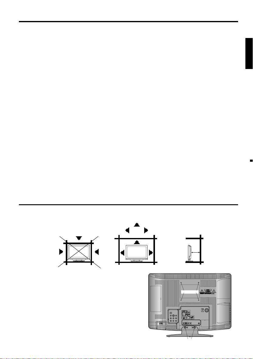
SAFETY PRECAUTIONS
The unit emits heat when in operation. Do not place any covers or blankets on the unit, this may cause overheating.
Do not block ventilation holes, or set up near radiators. Do not place in direct sunshine. When placing on a shelf leave 10 cm
(4 inches) free space around the entire unit.
10cm
10cm
Notes when mounting the LCD TV on a wall
If the unit is to be mounted on the wall, contact the retailer where
•
you purchased the LCD TV for advice, and have the equipment
professionally installed. Incomplete or improper installation may
cause injury to you, and/or damage to the LCD TV.
Bracket holes: To attach a wall mounting bracket (not supplied) attach
•
where indicated in the drawing right.
This manufacturer recommends professional installation.
•
Utilize an appropriate bracket and fasteners, sufficient to
•
accommodate the size and weight of the unit.
Assure the wall to which the unit is to be mounted will safely support
•
the size and weight of the unit, using the bracket and fasteners you
have selected.
Keep cords and cables connected to this flat panel display out of
•
reach of children.
To hang the television on a wall, remove these screws and then
•
remove a stand. Before performing work spread cushioning over the
base area to lay the TV on.
Bracket holes
Screws
5
Page 6
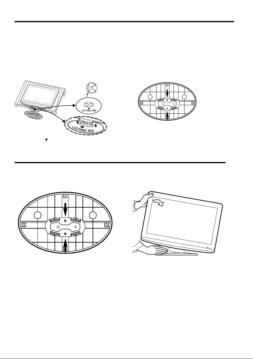
How to attach the stand
NOTE:
• Unplug the AC cord from the AC INPUT terminal.
• Before beginning this process, assure that TV is laid on a clean, safe, and cushioned space to avoid
any damage to the unit.
• Do not touch or press the TV-screen, glass might break under pressure.
Place the TV on its back onto a table.
Align the stand’s bottom-plate (supplied) as seen here.
It will fi t in only one direction.
Press it in direction of arrow until you hear ‘click’.
Finally secure the bottom-plate with 2 screws
(supplied).
Please assure “ ” mark on the stand is facing the LCD
panel side.
How to remove the stand
When you transport this product, remove the stand and pack fl at against the back of the unit in the
carton. To remove the stand, remove the two (2) screws from the bottom (see A), and hold the stand on a
fl at surface lifting one side of the unit until stand disconnects (see B).
AB
For wall mounting, the base must be removed. To disconnect the base/stand remove the two (2) screws from the
back (see page 5).
6
Page 7
Features
Integrated Digital Tuner - You can view digital broadcasts without using a Digital TV Set-Top Box.
•
Closed Caption Decoder With Full Text Mode - Displays text captions or full screen text on the screen for
•
hearing impaired viewers.
Picture Adjustments Using The Remote Control - The On-Screen display allows precise remote control
•
adjustment of BRIGHTNESS, CONTRAST, COLOR, TINT and SHARPNESS.
Programmable TV Sleep Timer - Operable from the remote control, the LCD TV can be programmed for up
•
to 120 minutes to turn off automatically.
•
V-Chip - The V-Chip function can read the rating of a broadcast program or movie content if the program is
encoded with this information. V-chip will allow you to set a restriction level.
•
Digital Audio Jack (Coaxial) - When a component with a built-in Dolby Digital decoder is connected, Dolby
Digital sound can produce the effect of being in a movie theater or a concert hall.
•
S-Video/Component Video Jacks - A VCR, DVD player, satellite receiver or other audio/video component
can be connected to this unit.
Video Input Jacks - This unit is equipped with 3 types of video input jacks. The component video in jacks and
•
S-video in jack enable you to watch the DVD player or the video devices with high quality picture.
•
On-Screen 3 Language Display - You can select one of 3 languages, English, French or Spanish for on-
screen programming.
* Manufactured under license from Dolby Laboratories. Dolby and the double-D symbol are trademarks of
Dolby Laboratories.
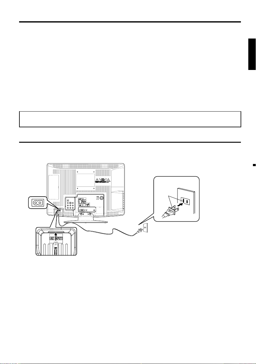
Power source
TO USE AC POWER
Connect the AC cord plug into this unit’s AC INPUT jack.
1.
Connect the AC cord into an AC outlet.
2.
ENGLISH
Wider Hole
and Blade
AC 120V, 60Hz
AC cord (supplied)
NOTE:
•
Please make sure to insert the cord securely at both the LCD TV and the wall outlet.
•
The AC cord has a grounding-type AC line plug. If the supplied AC cord does not match your AC outlet,
contact a qualified electrician, do not defeat the purpose of a grounding plug.
WARNING:
•
DO NOT CONNECT THIS UNIT TO THE POWER USING ANY DEVICE OTHER THAN THE SUPPLIED AC
CORD. THIS COULD CAUSE FIRE, ELECTRICAL SHOCK, OR DAMAGE.
DO NOT USE WITH A VOLTAGE OTHER THAN THE POWER VOLTAGE DISPLAYED. THIS COULD CAUSE
•
FIRE, ELECTRICAL SHOCK, OR DAMAGE.
CAUTION:
WHEN THIS UNIT IS NOT USED FOR A LONG TIME, (E.G., AWAY ON A TRIP) IN THE INTEREST OF
•
SAFETY, BE SURE TO UNPLUG IT FROM THE AC OUTLET.
DO NOT PLUG/UNPLUG THE PLUG WHEN YOUR HANDS ARE WET. THIS MAY CAUSE ELECTRICAL
•
SHOCK.
IF YOU NEED TO REPLACE THE SUPPLIED AC ADAPTER OR AC CORD, THE SPECIFIED ONE IS
•
RECOMMENDED. CONTACT CUSTOMER SERVICE AT 1-800-289-0980.
AC Outlet
7
Page 8

Contents
Before using your unit
IMPORTANT SAFETY INSTRUCTIONS ...........3
SAFETY PRECAUTIONS .................................5
How to attach the stand ....................................6
How to remove the stand ..................................6
Features ............................................................7
Power source ....................................................7
Contents ...........................................................8
Parts and functions ...........................................9
Remote control ...............................................10
Antenna connections ......................................11
Cable TV connections ..................................... 12
Connections to other equipment .....................13
TV operation
Starting setup .................................................15
TV operation ...................................................15
Quick guide for menu operation ...................... 16
Convenience functions ...................................17
Memorizing channels ......................................18
Checking the digital-signal strength ................19
Labeling channels ...........................................19
Labeling video inputs ......................................19
Setting the V-Chip ...........................................20
Closed Caption ...............................................21
CC advanced ..................................................21
Setting the picture size ....................................22
Additional information
Reception disturbances ..................................23
Troubleshooting ..............................................24
Specifications ................................................25
LIMITED WARRANTY ....................................26
8
Page 9
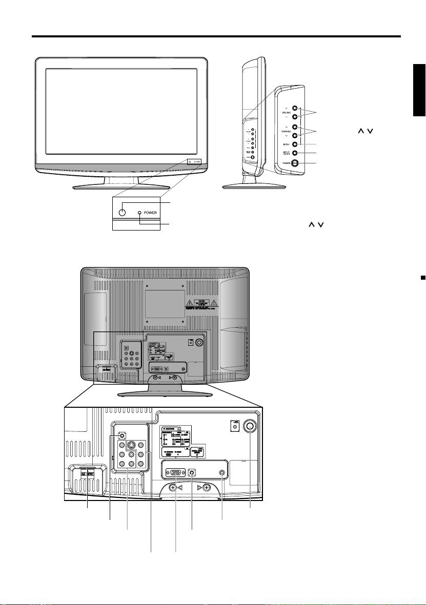
Parts and functions
Left sideFront
Rear
Remote sensor
POWER indicator
Red: Standby
Green: On
VOLUME +/– buttons
CHANNEL
MENU button
INPUT/ENTER button
POWER button
To display the menu screen.
Press MENU button to display the menu
screen.
CHANNEL
+/– buttons and INPUT/ENTER button
can be used to select the desired setting
during the menu screen operations.
/ buttons,
/ buttons
VOLUME
ENGLISH
AC INPUT jack
HEADPHONE jack
COMPONENT IN jacks
(Y/Pb/Pr/ AUDIO (L/R))
VIDEO IN jacks
(VIDEO/S-VIDEO/AUDIO (L/R))
RF (ANT) IN jack
COAXIAL DIGITAL AUDIO OUT jack
PC AUDIO IN jack
PC MONITOR IN jack
9
Page 10
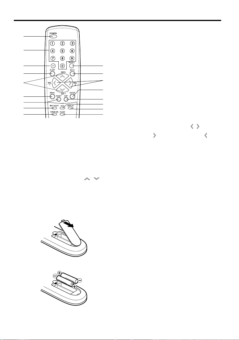
Remote control
6.MENU Button - Use to display the On-Screen
1
2
3
4
5
6
7
8
9
1.POWER Button - Used to turn the power on/off to
the LCD TV.
2.Direct Channel Selection Buttons (0-9) - Allows
direct access to any channel of the LCD TV.
3.– Button -This button is the “–” button used
when selecting digital channels. Also can display
the current channel number when viewing the
program.
4.SLEEP Button - To set the LCD TV to turn off
after a preset amount of time, use the SLEEP
button on the remote control.
5.CH (CHANNEL) + / – / CURSOR
Buttons - Used to operate the menu functions of
the LCD TV, and to change the channels of the
LCD TV.
Before using the remote control, batteries must first be installed.
10
11
12
13
14
15
16
17
/
HOW TO INSTALL BATTERIES
1. Open the battery compartment cover.
2. Install two “AAA” batteries (supplied).
3. Replace the battery compartment cover.
7.RESET Button - Press to reset the On-Screen
8.INPUT SELECT Button - Use to change the
9.SCREEN SIZE Button - Used to change the
10.RECALL Button - This button allows you to go
11.MUTE Button - To turn off the sound, press this
12.
13.ENTER Button - Use to enter or select
14.EXIT Button - Press to remove setup menu.
15.CCD Button - Used to display the Closed Caption
16.DISPLAY Button - When you press this button,
17.AUDIO Button - Change sound track language.
Use two “AAA” size batteries. The batteries may last
approximately one year depending on how much the
remote control is used. For best performance, it is
recommended that batteries should be replaced on a
yearly basis, or when the remote operation becomes
erratic. Do not mix old and new batteries or different
types.
BATTERY PRECAUTIONS
These precautions should be followed when using
batteries in this device:
•
Use only the size and type of batteries specified.
•
Be sure to follow the correct polarity when
installing the batteries as indicated in the battery
compartment. Reversed batteries may cause
damage to the device.
•
Do not mix different types of batteries together (e.g.
Alkaline and Carbon-zinc) or old batteries with fresh
ones.
•
If the device is not to be used for a long period of
time, remove the batteries to prevent damage or
injury from possible battery leakage.
•
Do not try to recharge batteries not intended to be
recharged; they can overheat and rupture. (Follow
battery manufacturer’s directions.)
menu function.
picture adjustments to their factory preset positions.
To use this function, select “Picture” or “Audio” in
the menu screen, then press this button.
external input.
picture size.
back to the previous channel selected by just
pressing the RECALL button. Press this button
again to return to the channel you were watching.
button once. The LCD TV will be silenced and
the symbol “Mute” will appear on the screen. The
muting feature can be released by pressing the
MUTE button again or one of the VOL (VOLUME)
+ or – buttons.
VOL (VOLUME) + / – / CURSOR
- Used to operate the menu functions of the LCD
TV. Press the
to decrease the sound level.
information for On-Screen operations.
menu screen.
the current information will be displayed on a
screen. To remove the display from the screen,
press this button again.
button to increase, or the button
/ Buttons
10
Page 11
Antenna connections
If you are using an indoor or outdoor antenna, follow the instructions below that correspond to your
antenna system. If you are using a Cable TV service, see page 12 for Cable TV connections.
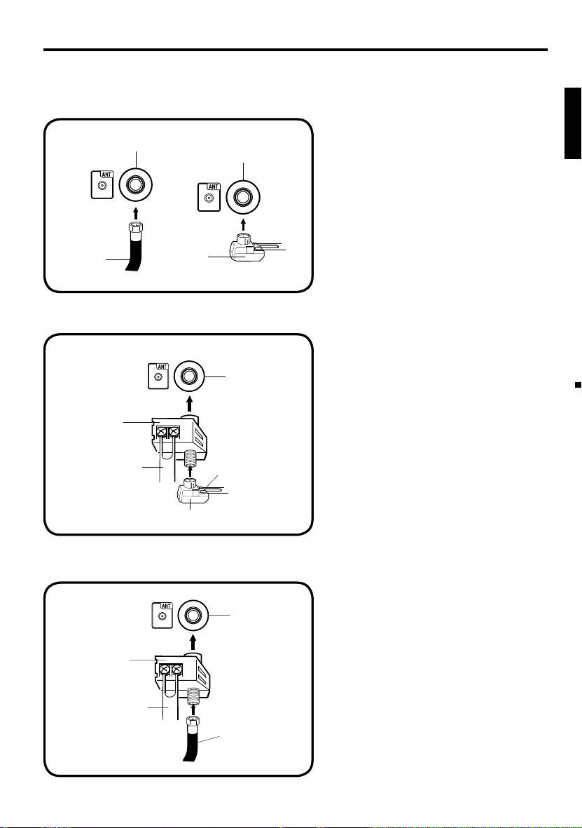
Combination VHF/UHF Antenna (Single 75 ohm cable or 300 ohm twin-lead wire)
Connect the 75 ohm cable from the combination
Antenna
Jack
Antenna
Jack
VHF/UHF antenna to the antenna jack.
If your combination VHF/UHF antenna has a 300
ohm twin-lead wire, the use of the 300-75 ohm
matching transformer may be necessary.
ENGLISH
75 ohm
Coaxial
Cable
300-75 ohm
Matching
Transformer
Combination VHF/UHF Antenna (Separate VHF and UHF 300 ohm twin-lead wires)
Connect the UHF 300 ohm twin-lead wire to
the Combiner (not supplied). Connect the VHF
300 ohm twin-lead wire to the 300-75 ohm
Matching Transformer. Attach the Transformer to
the Combiner, then attach the Combiner to the
Antenna Jack.
Combiner
UHF 300 ohm
300-75 ohm Matching Transformer
Antenna
Jack
VHF 300 ohm
Separate VHF/UHF Antennas (75 ohm VHF cable and 300 ohm UHF twin-lead wires)
Connect the VHF 75 ohm cable and UHF 300 ohm
twin-lead wire to the Combiner (not supplied). Attach
Antenna
Jack
the Combiner to the Antenna Jack.
Combiner
UHF 300 ohm
VHF 75 ohm
11
Page 12
Cable TV connections
This TV has an extended tuning range and can tune most cable channels without using a Cable TV
Converter box. Some cable companies offer “premium pay channels” where the signal is scrambled.
Descrambling these signals for normal viewing requires the use of a descrambler device which is
generally provided by the Cable TV company.
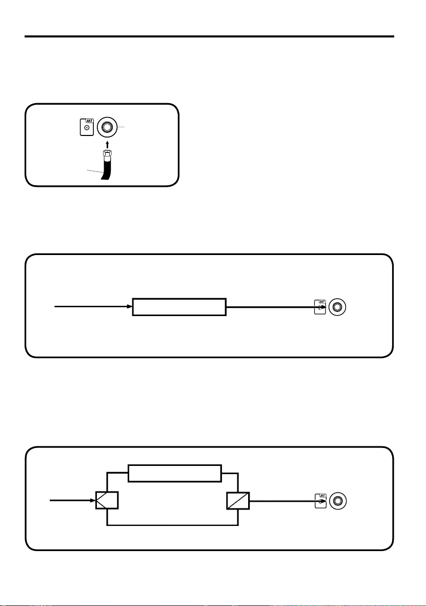
For subscribers to basic Cable TV service
For basic Cable TV service not requiring a Converter/
Descrambler box, connect the 75 ohm Coaxial Cable directly
Antenna
Jack
75 ohm
Coaxial Cable
For subscribers to scrambled Cable TV service
If you subscribe to a Cable TV service which requires the use of a Converter/Descrambler box, connect
the incoming 75 ohm Coaxial Cable to the Converter/Descrambler box. Using another 75 ohm Coaxial
Cable, connect the output jack of the Converter/Descrambler box to the Antenna Jack on the TV. Follow the
connections shown below. Set the TV to the output channel of the Converter/Descrambler box (usually channel
3 or 4) and use the Converter/Descrambler box to select channels.
Incoming
75 ohm
Cable TV
Cable
to the Antenna Jack on the back of the TV.
Converter/
Descrambler
75 ohm Cable to TV
Antenna
Jack
For subscribers to unscrambled Cable TV service with scrambled premium
channels
If you subscribe to a Cable TV service in which basic channels are unscrambled and premium channels require
the use of a Converter/Descrambler box, you may wish to use a signal Splitter and an A/B Switch box (available
from the Cable TV company or an electronics supply store). Follow the connections shown below. With the
switch in the “B” position, you can directly tune any nonscrambled channels on your TV. With the switch in the
“A” position, tune your TV to the output of the Converter/Descrambler box (usually channel 3 or 4) and use the
Converter/Descrambler box to tune scrambled channels.
Incoming
75 ohm
Cable TV
Cable
Splitter
Converter/
Descrambler
A/B Switch
75 ohm Cable to TV
A
B
Antenna
Jack
12
Page 13
Connections to other equipment
The exact arrangement you use to interconnect various video and audio components to this unit is dependent
on the model and features of each component. Check the Owner’s Manual provided with each component for
the location of video and audio inputs and outputs.
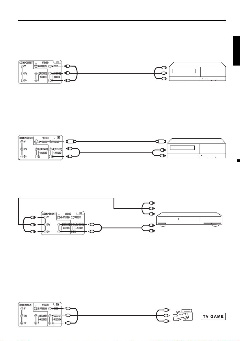
To connect the LCD TV to a VCR
Rear of the unit
To VIDEO/AUDIO IN
Video/Audio cord (not supplied)
To Video/Audio OUT
To connect the LCD TV to a VCR with an S-Video cord
If you connect a VCR with a S-Video cable to the S-VIDEO IN jack on the rear side of the unit, you must also
connect the audio cables to the AUDIO IN jacks on the rear of the unit.
The S-Video cable only carries the video signal. The audio signal is separate.
NOTE:
When the S-Video cable and the standard video cable are connected at the same time, the S-Video cable
•
takes precedence.
Rear of the unit
To S-VIDEO IN
S-Video cord (not supplied)
To S-Video OUT
VCR
VCR
ENGLISH
Audio cord (not supplied)
To AUDIO IN
To Audio OUT
To connect to a DVD player with Component Video Input
You can enjoy a high quality picture by connecting the unit’s COMPONENT VIDEO OUT jacks of your DVD
player with the COMPONENT video cables (not supplied).
Component video cord (not supplied)
Rear of the unit
To component AUDIO IN
Audio cord
(not supplied)
To COMPONENT IN
NOTE:
Component Video input of the unit are for use with a device which output 480i/1080i interlaced signals and
•
480p/720p progressive signals.
To connect the TV to a camcorder, or a TV Game
To playback from a camcorder, connect the camcorder to the unit as shown.
This unit can also be used as a display device for many video games. However, due to the wide variety of
signals generated by these devices and subsequent hook-up variations required, they have not all been
included in the suggested connection diagrams. You’ll need to consult each component’s Owner’s Manual for
additional information.
Rear of the unit
To VIDEO/AUDIO IN
Video/Audio cord (not supplied)
To Component OUT
Y
b
P
Pr
To Audio OUT
To Video/Audio OUT
DVD
or
13
Page 14
Connections to other equipment
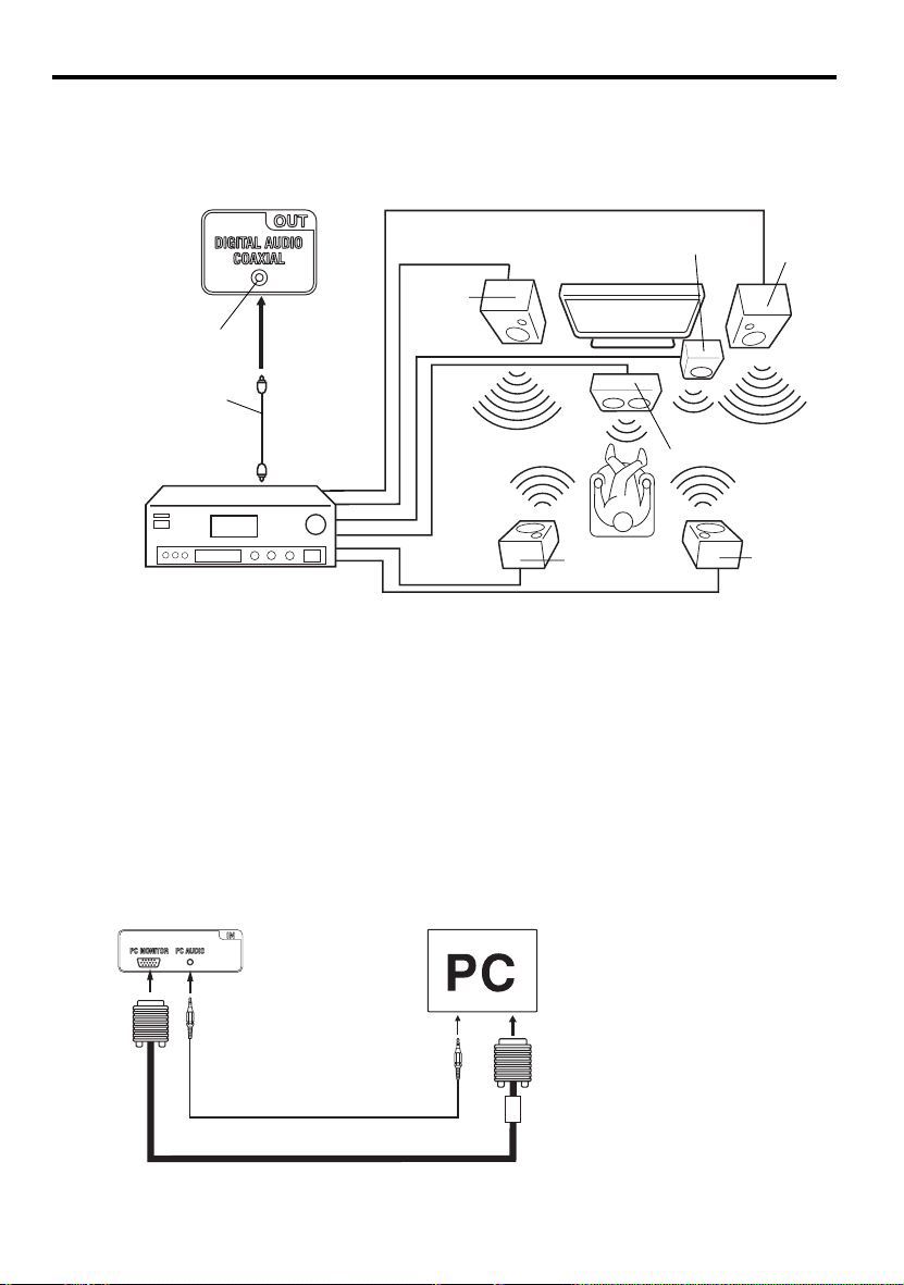
Using an AV Amplifier with built-in digital surround
If you are using an Amplifier with built-in digital surround sound, you can enjoy various audio systems including
Dolby Digital Surround audio that sounds just like the movie.
Connect an AV amplifier with built-in Dolby Digital decoder, etc. as shown below.
Rear of the unit
Front
Speaker
(Right)
To COAXIAL DIGITAL
AUDIO OUT
Coaxial digital cable
(not supplied)
Front
Speaker
(Left)
Subwoofer
TV
To Coaxial
Digital Audio IN
AV Amplifier with built-in digital surround
decoder as listed above
Surround
Speaker (Left)
Center Speaker
Surround
Speaker
(Right)
NOTE:
When you are viewing digital broadcast, this unit will not work in conjunction with DTS audio or MPEG audio.
•
There will be no sound output if connected to an AV amplifier with a built-in DTS decoder or MPEG decoder.
To connect the TV to a PC (Personal Computer)
Before you connect this TV to your PC, change the adjustment of your PC’s Resolution and
Refresh rate (60 Hz).
Connect one end of a (male to male) VGA cable to the video card of the computer and the other end to the
connector PC MONITOR on the rear of the
TV
. Attach the connectors firmly with the screws on the plug.
of a Multimedia computer, connect the audio cord to the audio output of your Multimedia computer and to the
AUDIO connector of the PC AUDIO IN jack of the TV. Press INPUT SELECT on the remote control to select PC
mode. Switch on the computer. The TV can operate as the computer monitor.
Rear of the unit
Monitor Display modes
MODE Resolution Refresh rate
VGA 640x480 60/ 72/ 75 Hz
VGA 720x400 70Hz
To PC
MONITOR
IN
To PC AUDIO IN
SVGA 800x600 56/ 60/ 72/ 75 Hz
XGA 1024x768 60/ 70/ 75 Hz
WXGA 1280x768 60Hz
WXGA 1280x720 60Hz
Audio cord (not supplied)
VGA cable (not supplied)
WXGA 1360x768 60Hz
To return to normal mode
Press INPUT SELECT again.
VGA
In case
NOTE:
The on-screen displays will have a different appearance in PC mode than in TV mode.
•
If there is no video signal from the PC when the unit is in PC mode, “No signal” will appear on the TV-screen.
•
14
Page 15
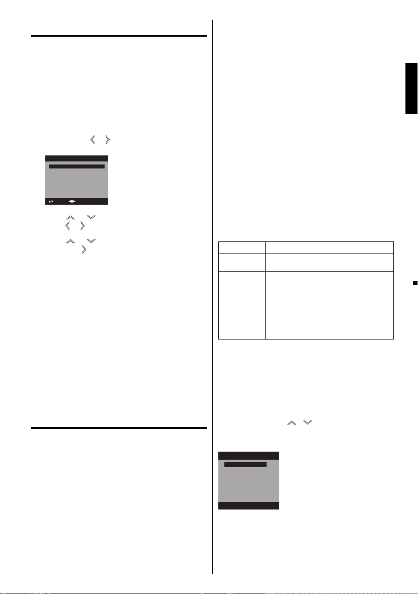
Starting setup
The Starting Setup menu appears the first time
you turn on the TV, and assists you to select the
menu language, specify the Air/Cable setting,
and program your channels automatically.
IMPORTANT: Make sure that the antenna or cable
TV system connection is made!
To turn on the TV, press POWER (POWER
1
indicator on the front of the unit changes green.
It may take approx. 10 seconds for a picture to
appear on screen.). The starting setup function
begins. Press
language.
Auto Setup
Language English
Signal Type Cable
Automatic Search Start
: Select
Press or to select “Signal Type”, then
2
press
Press or to select “Automatic Search”,
3
then press
Now the “Auto Setup” starts. After the starting
4
setup is completed, the TV channel appears on
the screen.
•
Depending on the reception condition, it may
take from 15 minutes to 30 minutes to complete
memorizing digital cable channels. Please be
patient.
NOTE:
If you press EXIT in the process of “Auto Setup”,
•
the Starting Setup stops and changes to the normal
screen.
When you make a menu selection, your changes
•
occur immediately. You do not have to press EXIT to
see your changes.
When you are finished programming the menus,
•
press EXIT.
or to select your desired
: Adjust
or to select “Cable” or “Air”.
or ENTER.
TV operation
To turn on the TV, press POWER.
1
(POWER indicator on the front of the unit
changes green. It may take approx. 10 seconds
for a picture to appear on screen.)
Adjust the volume level by pressing VOL + or – .
2
The volume level will be indicated on the screen
by blue bars. As the volume level increases, so do
the number of bars. If the volume decreases, the
number of blue bars also decreases.
Set the Signal Type option to the appropriate
3
position (see “Air/Cable selection” on page 18).
Press the Direct Channel Selection (0-9, –)
4
buttons to select the channel.
(If you press only channel number, channel
selection will be delayed for a few seconds.)
TO SELECT ANALOG CHANNELS
1-9: Press 1-9 as needed. Example, to
10-99: Press the 2 digits in order. Example,
100-135: Press the 3 digits in order. Example, to
TO SELECT DIGITAL CHANNELS
Press the first 3 digits, then press the – button,
followed by the remaining number.
Example, to select channel 015-001, press 0, 1,
5, –, 0, 0, 1, then press ENTER.
•
•
The same program may be available on either
•
VHF/UHF/CABLE CHANNELS
14-69
NOTE:
If a channel with no broadcast is selected, the
•
sound will automatically be muted.
It may take a few seconds for a digital channel
•
picture to appear on screen after being selected.
To select the video input source
To view a signal from another device connected to
your LCD TV, such as a VCR player, press INPUT
SELECT, then press
Number buttons (0-3), then press ENTER. You can
select TV, Video, Component or PC depending on
which input jacks you used to connect your devices.
Source Selection
0.TV
1.Video
2.Component
3.PC
[0-3]:Select
CH +/
Press and release CH +/-. The channel automatically
stops at the next channel set into memory.
For proper operation, before selecting channels, they
should be set into the memory. See “Memorizing
channels” on pages 18 and 19.
select channel 2, press 2, then press
ENTER.
to select channel 12, press 1, 2, then
press ENTER.
select channel 120, press 1, 2, 0, then
press ENTER.
If a channel is selected with only audio content,
“Audio only” will be displayed on the screen.
If a channel is selected with a weak digital
signal, “Digital channel signal strength is low”
will be displayed on the screen.
an analog channel or a digital channel. You may
choose to watch either format.
If a channel is selected to which you have not
subscribed,
be displayed on the screen.
Air Cable
VHF
2-13
UHF
“Digital channel is encrypted” will
VHF
2-13
STD/HRC/IRC
14-36 (A) (W)
37-59 (AA) (WW)
60-85 (AAA) (ZZZ)
86-94 (86) (94)
95-99 (A-5) (A-1)
100-135 (100) (135)
01 (4A)
/ or corresponding
-
ENGLISH
15
Page 16

DISPLAY
Press DISPLAY to display the current information on
the screen.
When the TV receives a digital signal, the digital
information will appear.
62-001 HDTV Moving Picture1
CH-1
Digital Air
No Program Information is available
Full
1080i
Sleep Timer
Off
English
Channel number• Station name•
Broadcast program name
Channel label (if preset)•
•
V-Chip rating• Signal type•
Sleep timer• Audio language•
Program guide• Picture size•
Resolution•
When the TV receives a analog signal, the analog
information will appear.
14
Analog Cable
Mono
Full
480i
Sleep Timer
Off
Channel number• Channel label (if preset)•
V-Chip rating• Signal type•
Sleep timer• Picture size•
Audio information
• Resolution•
(Stereo, SAP or Mono)
Press DISPLAY again to clear the call display.
NOTE:
•
After a few seconds, DISPLAY screen will return to
normal TV-operation automatically.
RECALL
This button allows you to go back to the last channel
selected by pressing RECALL. Press RECALL again to
return to the last channel you were watching.
MUTE
Press MUTE to switch off the sound. The TV’s sound
will be silenced and “Mute” will appear on the screen.
The sound can be switched back on by pressing this
button again or the VOL + or –.
SLEEP
To set the TV to turn off after a preset amount of time,
press SLEEP on the remote control. The clock will
count up 10 minutes for each press of the SLEEP button (Off, 0h 10m, 0h 20m, ..., 2h 0m). After the sleep
timer is programmed, the display will appear briefly
every ten minutes to remind you that the sleep timer
is operating. To confirm the sleep timer setting, press
SLEEP and the remaining time will be displayed for a
few seconds. To cancel the sleep timer, press SLEEP
repeatedly until the display turns to Off.
Quick guide for menu
operation
Call menu and for example: Select Language.
Press INPUT SELECT to select TV mode.
1
Press MENU. The TV menu screen will appear.
2
3
4
5
NOTE:
•
Main Menu
Picture
Audio
Channel
Lock
Setup
: Select ENTER:Set
>>
Press or to select “Setup”, then press or
ENTER.
Press or to select “Language”, then press
/ to select the desired language.
…on the following pages the menu can be called
in the same way as here.
Press EXIT to return to the normal screen.
If no buttons are pressed for more than about 60
seconds, the menu screen will return to normal
operation automatically.
16
Page 17

Convenience functions
You can change the default settings to convenience use.
Icon Selected Items Setup hint
Picture Picture
Setting
Picture
Preference
Picture Size See page 22.
Film Mode On/Off A smoother motion may be obtained by setting the Film Mode to “On”
PC Setting Hor Position /
Audio Bass / Treble / Balance You can adjust the sound quality to your preference.
Channel Add / Delete See page 18.
Lock See page 20.
Setup Closed Caption See page 21.
DNR On/Off DNR (Digital Noise Reduction) can reduce the roughness of the picture.
MTS Stereo / Mono
Surround On/Off The dynamic presence and sound created offers a thoroughly enjoyable
Audio Language When two or more audio languages are included in a digital signal, you can
DTV Signal See page 19.
Auto Ch Memory See page 18.
Ch Label See page 19.
Language You can choose from three different languages (English, Français (French)
Video Label See page 19.
Auto Shut Off On/Off If the Auto Shut Off feature is On, a station being viewed stops
Reset The Reset function returns your settings to the factory settings.
Brightness
/ Contrast /
Sharpness /
Color / Tint
Color
Temperature
Backlight The Backlight feature adjusts the screen brightness for improved picture
Sports Bright and dynamic picture (factory-set)
Standard Standard picture quality (factory-set)
Movie Movie-like picture setting (factory-set)
Memory Your personal preferences (set by you; see “Picture Setting”)
Ver Position
Clock To minimize any vertical bars or stripes visible on the screen background.
Phase This must be adjusted after the frequency has been set optimize picture
Auto Adjust To adjust the all PC settings automatically.
/ SAP
You can adjust the picture quality to your preference.
Bluish (Cool) / Neutral (Standard) / Reddish (Warm)
clarity.
when you view a DVD from the DVD player connected with the component
input.
To adjust the horizontal / vertical position of the image on the PC Monitor
screen. Each video standard will require a different value for this setting.
quality.
The multi-channel TV sound (MTS) feature provides high-fidelity stereo
sound. MTS also can transmit a second audio program (SAP) containing a
second language or other audio information.
When the TV receives a stereo or SAP broadcast, the word “Stereo” or
“SAP” displays on-screen every time you press DISPLAY.
listening experience.
select one of the audio language. (This function is available only for digital
broadcast.)
and Español (Spanish)) for the on-screen displays.
Select the language you prefer first, then proceed with the other menu
options.
broadcasting and the TV is not operated, the TV will automatically shut
itself off after 15 minutes.
“Picture Size”, “MTS” and “Audio Language” cannot be reset by this
function.
ENGLISH
17
Page 18

Memorizing channels
This TV is equipped with a channel memory
feature which allows channels to skip up or down
to the next channel set into memory, skipping
over unwanted channels. Before selecting
channels, they must be programmed into the
TV’s memory. To use this TV with an antenna, set
the Signal Type option to the Air mode. When
shipped from the factory, this menu option is in
the Cable mode.
Air/Cable selection
Select “Channel”, then press or ENTER.
1
Press or to select “Auto Ch Memory”, then
2
3
4
CABLE CHART
The chart below is typical of many cable system
channel allocations.
or ENTER.
press
Press or to select “Signal Type”.
Press or to select “Air” or “Cable”.
Air - VHF/UHF channels
Cable - CABLE TV channels
Auto Ch Memory
Signal Type Cable
Automatic Search Start
: Adjust
: Select
The TV will begin memorizing all the channels
4
available in your area.
•
It may take from 15 minutes to 30 minutes to
complete memorizing digital cable channels.
Depending on the reception condition, a bar
display may not advance for several minutes,
please be patient.
NOTE:
Memorizing channels is best accomplished during
•
evening “PRIMETIME” hours, as more stations are
broadcasting digital signals. Memorizing channels can
only be accomplished while a station is broadcasting
a digital signal to set that channel into memory.
•
If you are unsure of the digital channels available
in your area, you may visit www.antennaweb.org to
receive a list based on your address or zip code.
Should you require further assistance you may call
our toll-free customer service line at 1-800-289-0980.
•
New digital channels may be added to your area
periodically, it is recommended to perform the
“Automatic Search” procedure regularly.
Adding Channel
If you find a new digital channel unregistered, you can
add the new channel into the channel memory.
Tune in the new channel.
1
Select “Channel”, then press or ENTER.
2
Press or to select “Add/Delete”, then press
3
or ENTER.
Add/Delete
Adding Channel >>
Add/Delete >>
Clear All >>
NOTE:
It may take a few seconds for a digital channel
•
picture to appear on screen after being selected.
Automatic search
1
Select “Channel”, then press or ENTER.
Press or to select
2
press
or ENTER.
Press or to select “Automatic Search”,
3
then press
Auto Ch Memory
Signal Type Cable
Automatic Search Stop
Analog Channel Found : 7
Digital Channel Found : 5
Programming Now
: Select
or ENTER.
ENTER:Cancel
“Auto Ch Memory”, then
18
: Select ENTER:Set
Press or to select “Adding Channel”, then
4
press
or ENTER. The new channel will be
added into the channel memory.
Add/Delete channel
You can select the channel that you want to skip.
Select “Channel”, then press or ENTER.
1
Press or to select “Add/Delete”, then press
2
or ENTER.
Press or to select “Add/Delete”, then press
3
or ENTER.
Press or to select the channel that you
4
want to skip.
Add/Delete
CH Signal
2 Analog
3 Analog Add
3-001 Digital Delete
3-002 Digital Add
4 Analog Delete
: Select
Press or to select “Add” or “Delete”,
5
whichever function you want to perform.
Repeat steps 4 - 5 for other channels you want to
6
add or delete.
Add
: Adjust
Page 19

Clear All
All channels are deleted from the channel memory.
Select “Channel”, then press or ENTER.
1
Press or to select “Add/Delete”, then press
2
or ENTER.
Press or to select “Clear All”, then press
3
or ENTER.
Add/Delete
Adding Channel >>
Add/Delete >>
Clear All >>
: Select ENTER:Set
Checking the digitalsignal strength
This TV will allow you to view the digital signal
meter for digital channels.
Select “Channel”, then press or ENTER.
1
Press or to select “DTV Signal”.
2
Press or ENTER to check the Digital-signal
3
strength.
The Digital-Signal strength screen will appear.
If necessary, adjust the direction of the antenna to
obtain the maximum signal strength.
DTV Signal
0 50 100
Signal Level
NOTE:
Signal meter feature is not available for analog
•
channels.
After 240 seconds, DTV Signal screen will return to
•
normal TV-operation automatically.
Labeling channels
Channel label appear with the channel number
display each time you turn on the TV, select a
channel, or press DISPLAY.
You can choose any four characters to identify a
channel.
To create channel labels
Select “Channel”, then press or ENTER.
1
Press or to select “Ch Label”, then press
2
or ENTER.
The “Ch Label” menu will appear.
Press or to select a channel you want to
3
label, then press
.
Ch Label
Channel Number 15-1
Ch Label
Label Clear >>
: Adjust
: Select
Press or repeatedly until the character you
4
want appears in the first space.
Ch Label
Channel Number 15-1
Ch Label A
Label Clear >>
: Adjust
: Select
The characters rotation as follows:
If the character which you desire appears, press
ENTER.
Repeat this step to enter the rest of the characters.
If you would like a blank space in the label name,
you must choose the empty space from the list of
characters.
When you finish inputting the label name, press
5
EXIT to return to the normal screen.
Repeat steps 3-4 for other channel. You can
6
assign a label to each channel.
ENTER:Set
SPACE
, () @ / + =
-
-
To clear a Ch Label
After step 3 above, press or to select “Label
Clear”, then press
NOTE:
•
The channel labels will be reset after “Automatic
Search” on page 18.
or ENTER.
Labeling video inputs
The Video Label feature allows you to label each
input source for your TV.
Select “Setup”, then press or ENTER.
1
Press or to select “Video Label”, then
2
press
or ENTER.
Press or to select an input which you want
3
to label.
Press or to select the desired label for that
4
input source.
Video Label
Video -
Component -
: Adjust
: Select
– : Uses the default label name
VCR : Video cassette recorder
DVD : DVD video
DTV : Digital TV set-top box
SAT : Satellite box
CBL : Cable box
ENGLISH
19
Page 20

Setting the V-Chip
An age limitation can be set to restrict children from
viewing or hearing violent scenes or pictures that you
may choose to exclude. The restriction applies to “TV
Rating” and “Movie Rating” if this data is transmitted.
You may set this restriction separately. To use the
V-Chip function, you must register a password.
To register a password
Select “Lock”, then press or ENTER.
1
Select and enter your password (4 digits) using
2
Number buttons (0-9), then press ENTER.
Lock
New Password
[0-9]
: Select ENTER:Set
“ ” appears instead of the number.
Enter the same password again to confirm, then
3
press ENTER.
The password is now registered.
NOTE:
If you forget the password, contact Customer
•
Service at 1-800-289-0980 for assistance.
Your original remote control will be required.
To avoid forgetting the password, write it down and
•
keep in a safe place.
To set the V-Chip
Select “Lock” menu, then press or ENTER.
1
Use Number buttons (0-9) to enter your
2
password, then press ENTER. Then Lock menu
will appear.
Press or to select “V-Chip”, then press
3
or to select “On” .
Press or to select “V-Chip Set”, then press
4
or ENTER.
The V-Chip Set Menu appears.
Press or to select which rating will be
5
used, then press
will appear.
TV Rating
TV Rating
TV-Y
TV-Y7
TV-G
TV-PG
TV-14
TV-MA
You can set the rating using age level and genre.
Age:
TV-Y : All children
TV-Y7 : 7 years old and above
TV-G : General audience
TV-PG : Parental guidance
TV-14 : 14 years old and above
TV-MA : 17 years old and above
20
_
* * *
ALL D L S V FV
ENTER:Set
: Select
or ENTER. Each rating below
Genre:
ALL : All
D : Dialogue
L : Language
S : Sex
V : Violence
FV : Fantasy Violence
Movie Rating
Movie Rating
G
PG
PG-13
R
NC-17
X
: Select
G : All ages
PG : Parental guidance
PG-13 : Parental guidance
R : Under 17 years old parental guidance
NC-17 : 17 years old and above
X : Adult only
Press / / / to select the desired rating, then
6
press ENTER.
Press EXIT to return to the normal screen.
7
V-Chip function is activated now.
To use the TV after the TV is protected.
When a program is received that is blocked by the
V-Chip, press MUTE, then enter your password.
The protection will be temporarily overridden. If the
TV is turned off or the channel is changed, the V-Chip
restriction will be reactivated.
NOTE:
The V-Chip function is activated only on programs
•
and input sources that include a rating signal.
ENTER:Set
less than 13 years old
suggested
To change the password
Select “Lock”, then press or ENTER.
1
Use Number buttons (0-9) to enter your password,
2
then press ENTER. The Lock menu will appear.
Press or to select “Change Password”,
3
then press
The Change Password screen will appear.
Enter a new password using Number buttons
4
(0-9), then press ENTER.
Enter the same password again to confirm, then
5
press ENTER.
The password is now registered.
or ENTER.
Downloading the additional V-Chip rating system
As a supplement to the standard V-Chip rating
system, your television will be able to download an
additional rating system, if such a system becomes
available in the future.
To download the additional V-Chip rating system
(when available)
Select “Lock”, then press or ENTER.
1
Use Number buttons (0-9) to enter your password,
2
then press ENTER. The Lock menu will appear.
Page 21

Press or to select “V-Chip”, then press
3
or to select “On”.
Press or to select “V-Chip Set (DTV)”, then
4
press
or ENTER.
If the TV is not storing the additional rating
5
system, the TV will begin downloading it, which
may take some time to be completed.
Set your preferred content rating limits for the
6
additional rating system.
You also need “Update” procedure to update
7
rating information.
NOTE:
You can only download the additional V-Chip rating
•
system when your TV is receiving a digital signal.
When you download the additional rating system, it
•
may take some time for the download to occur.
The V-Chip rating information and system are not
•
determined or controlled by the TV.
The standard V-Chip rating system is available
•
whether your TV is receiving a digital signal or not,
and will block both analog and digital programs. To
set the restriction level using the standard V-Chip
rating system, select V-Chip Set in step 4.
The downloadable V-Chip rating system is an
•
evolving technology, and availability, content, and
format may vary.
You cannot select this feature if the TV is not
•
receiving a digital signal for the current station.
To clear the all V-Chip settings
Select “Lock”, then press or ENTER.
1
Use Number buttons (0-9) to enter your password,
2
then press ENTER. The Lock menu will appear.
Press or to select “V-Chip Clear”, then
3
press
or ENTER.
The Password screen will appear.
Use Number buttons (0-9) to enter your
4
password, then press ENTER. All your settings
return ro the factory settings.
Closed Caption
WHAT IS CLOSED CAPTIONING?
This television has the capability to decode and
display Closed Captioned television programs.
Closed Captioning will display text on the screen
for hearing impaired viewers or it will translate and
display text in another language.
Captions: This Closed Caption Mode will display
text on the screen in English or another language.
Generally, Closed Captions in English are transmitted
on C1 and Closed Captions in other languages are
transmitted on C2.
Text: The Text Closed Caption Mode will usually fill
1/2 of the screen with a programming schedule or
other information.
Select “Setup”, then press or ENTER.
1
Press or to select “Closed Caption”, then
2
press
or ENTER.
The Closed Caption menu will appear.
Press or to set “CC Setting” to “On”.
3
On: Captions will be displayed on the screen.
Off: Captions will not be displayed on the screen.
Press or to select “Analog Caption” or
4
“Digital Caption”.
When you select “Analog Caption”, you can
choose C1, C2, C3, C4, T1, T2, T3 and T4.
When you select “Digital Caption”, you can
choose from CS1, CS2, CS3, CS4, CS5 and CS6.
Press or to select the desired Closed
5
mode for both Digital and Analog Caption.
Press or to select “CC Priority”, then
6
press
or to select “Digital CC” or “Analog CC”.
NOTE:
Depending on the broadcast signal, some
•
Analog Captions will function with a Digital
broadcast signal. This step prevent that two
kind of captions are overlapping.
NOTE:
•
If the program or video you selected is not closedcaptioned, no captions will display on-screen.
•
If text is not available in your viewing area, a black
rectangle may appear on-screen. If this happens,
set the CC Setting to “Off”.
When selecting Closed Captions, the captioning will
•
be delayed approx. 10 seconds.
•
If no caption signal is received, no captions will appear,
but the television will remain in the Caption Mode.
•
Misspellings or unusual characters may
occasionally appear during Closed Captioning.
This is normal with Closed Captioning, especially
with live programs. This is because during live
programs, captions are also entered live. These
transmissions do not allow time for editing.
•
When Captions are being displayed, on-screen
displays, such as volume and mute may be seen
but may interfere with Closed Captions.
•
Some cable systems and copy protection systems
may interfere with the Closed Captioned signal.
•
If using an indoor antenna or if TV reception is
very poor, the Closed Caption Decoder may not
appear or may appear with strange characters or
misspelled words. In this case, adjust the antenna
for better reception or use an outdoor antenna.
Caption
CC advanced
When you have selected Custom as the display
method, you can adjust the various setting listed
below as follows:
This feature is designed to customize Digital Captions
only.
Select “Setup”, then press or ENTER.
1
Press or to select “Closed Caption”, then
2
press
or ENTER.
The Closed Caption menu will appear.
Press or to set “CC Setting” to “On”.
3
Press or to select “Digital CC Preset”, then
4
press
or to select “Custom”.
ENGLISH
21
Page 22

Press or to select “CC Advanced”, then
5
press
or ENTER.
The CC Advanced menu will appear.
Press or to select the desired item, then
6
or to change the setting.
press
CC Advanced
Text Size Auto
Text Type Auto
Text Edge Auto
Text Color Auto
Text Opacity Auto
Background Color Auto
Background Opacity Auto
: Adjust
: Select
You can select from among the following items
and parameters.
Text Size: Auto, Small, Standard, Large
Text Type: Auto, Style1, Style2, Style3, Style4,
Style5, Style6, Style7
Text Edge: Auto, None, Raised, Depressed,
Uniform, Left Shadow, Right
Shadow
Text Color: Auto, Black, White, Red, Green,
Blue, Yellow, Magenta, Cyan
Text Opacity: Auto, Solid, Transparent,
Translucent, Flashing
Background
Color:
Background
Opacity:
Auto, Black, White, Red, Green,
Blue, Yellow, Magenta, Cyan
Auto, Solid, Transparent,
Translucent, Flashing
NOTE:
•
You cannot set both “Text Color” and “Background
Color” as a same color.
•
You cannot set both “Text Opacity” and “Background
Opacity” to “Transparent”.
Setting the picture size
Cinema Wide1 (for 4:3 format programs)
To fill the screen, the right and left edges are
extended, however; the center of the picture remains
near its former ratio.
The top and bottom edges of the picture may be hidden.
Cinema Wide2 (for letter box programs with
subtitles)
To fill the width of the screen, it is extended
horizontally. However; it is only slightly extended at the
top and the bottom.
The top and bottom edges of the picture may be hidden.
Cinema Wide3 (for letter box programs with
subtitles)
To fill the width of the screen, it is extended
horizontally. However; it is only slightly extended at the
top and the bottom.
The top and bottom edges of the picture may be hidden.
You can view 480i and 480p format programs in a
variety of picture sizes— Natural, Cinema Wide1,
Cinema Wide2, Cinema Wide 3, Full and Native.
Selecting the picture size
Select “Picture”, then press or ENTER.
1
Press or to select “Picture Size”, then
2
press
or ENTER to display Picture Size menu.
Press
(0-4)
/ or corresponding Number buttons
to select the desired picture size, as
described below.
Picture Size
0.Natural
1.Cinema Wide1
2.Cinema Wide2
3.Cinema Wide3
4.Full
[0-4]:Select
NOTE:
Selectable picture sizes may vary depending on the
•
input source or broadcast signal.
Picture Size menu also can be displayed by
•
pressing SCREEN SIZE on the remote control.
Natural
In some cases, this image will display the size of
standard 4:3 with a black side bar.
22
A B C D E F G - - - - - - - - - - - - - - - -
A B C D E F G - - - - - - - - - - - - - - - - - - - - - - - - - -
Full (for 16:9 source programs)
Full will display the picture at the maximum size.
Native (for PC mode only)
Detects the resolution of the signal of the image and it
will be shown on the screen with same amount of pixels.
NOTE:
•
Some High Definition and/or Digital broadcasts may
not allow you to change the picture size.
•
In COMPONENT mode with a scanning rate of
720p or 1080i, only the Cinema Wide2 and Full
picture size feature is available.
•
In PC Mode, only the Natural, Full and Native
picture size features are available. In PC Mode
(WXGA), only the Full and Native picture size
features are available.
Page 23

Reception disturbances
Most types of television interference can be remedied by adjusting the height and position of the VHF/
UHF antenna. Outdoor antennas are recommended for best results. The most common types of television
interference are shown below. If one of these symptoms appear when the TV is connected to a Cable TV
system, the disturbance may be caused by the local Cable TV company broadcast.
IGNITION
Black spots or horizontal streaks may appear, the picture may flutter or
drift. Usually caused by interference from automobile ignition systems,
neon lamps or AC powered tools and appliances such as drills or hair
dryers.
GHOSTS
Ghosts are caused by the television signal following two paths. One is the
direct path and the other is reflected by tall buildings, hills or other large
objects. Changing the direction or position of the antenna may improve
the reception.
SNOW
If the TV is located far from the TV station, in a fringe reception area where
the signal is weak, small dots may appear in the picture.
If the signal is extremely weak, the installation of a larger external antenna
may be necessary.
ENGLISH
RADIO FREQUENCY INTERFERENCE (RFI)
Caused by two-way radios, this type of interference produces moving
ripples or diagonal streaks in the picture. Some cases may cause a loss of
contrast in the picture. Changing the direction and position of the antenna
or installing an RFI filter may improve the picture.
PICTURE SIZE VARIATION
A slight picture size variation is normal when you adjust the CONTRAST or
BRIGHTNESS settings.
CARE AND MAINTENANCE
To prevent fire or shock hazard, disconnect the TV from the power source before cleaning.
The finish on the cabinet may be cleaned with mild soap and a soft, damp cloth and cared for as other furniture.
Use caution when cleaning or wiping the plastic parts.
23
Page 24

Troubleshooting
Use the following checklist for troubleshooting if you have problems with your LCD TV. Consult your local dealer
or service outlet if problems persist. Be sure all connections are properly made when using with other units.
SYMPTOMS POSSIBLE SOLUTIONS
TV does not
operate.
Poor sound
or no sound.
Poor picture
or no picture.
Poor
reception on
some
channels.
Poor color or
no color.
Picture
wobbles or
drifts.
Make sure the power cord is plugged in.
•
Try another AC outlet.
•
Power is off, check fuse or circuit breaker.
•
Unplug unit for an hour, then plug it back
•
in.
Station or Cable TV experiencing
•
problems, tune to another station.
Check sound adjustments (Volume and
•
Mute).
Check for sources of possible
•
interference.
Station or Cable TV experiencing
•
problems, tune to another station.
Make sure channels are set into memory.
•
Check antenna or Cable TV
•
connections, adjust antenna.
Check for sources of possible
•
interference.
Check picture control adjustments.
•
Station or Cable TV experiencing
•
problems, tune to another station.
Make sure channels are set into memory.
•
Station is weak, adjust antenna to
•
receive desired station.
Check for sources of possible
•
interference.
Station or Cable TV experiencing
•
problems, tune to another station.
Make sure channels are set into memory.
•
Check picture control adjustments.
•
Check antenna or Cable TV
•
connections, adjust antenna.
Check for sources of possible
•
interference.
Station or Cable TV experiencing
•
problems, tune to another station.
Make sure channels are set into memory.
•
Cable TV company is scrambling signal.
•
•
Adjust antenna.
SYMPTOMS POSSIBLE SOLUTIONS
Digital
broadcasting
screen
problem.
No CATV
reception.
Horizontal or
diagonal bars
on screen.
No reception
above
channel 13.
No Remote
operation.
TV shuts off.
Closed Caption is not
activated.
TV is not
shown in your
language.
Check digital signal strength.•
Check all Cable TV connections.
•
Set Air/Cable menu option to the Cable
•
mode.
Station or Cable TV system problems,
•
try another station.
Check antenna connections, adjust or
•
re-direct antenna.
Check for sources of possible
•
interference.
Make sure Signal Type option is in the
•
appropriate mode.
If using antenna, check UHF antenna
•
connections.
Batteries are weak, dead or inserted
•
incorrectly.
Remote is out of range, move closer to
•
TV (within 15 feet).
Make sure Remote is aimed at sensor.
•
Confirm there are no obstructions
•
between the Remote and the TV.
Make sure the power cord is plugged in.
•
Sleep Timer is set.
•
Power interrupted.
•
TV station experiencing problems or
•
program tuned is not closed captioned.
Try another channel.
Check Cable TV connection or VHF/UHF
•
antenna, reposition or rotate antenna.
Set closed caption decoder in the menu.
•
•
Select proper language in the menu
options.
FOR CUSTOMER SERVICE, ADDITIONAL SET-UP AND OPERATING ASSISTANCE, OR TO ORDER ACCESSORIES PLEASE CALL:
1-800-289-0980
WHEN CALLING CUSTOMER SERVICE – PLEASE HAVE YOUR MODEL NUMBER READY
OR WRITE TO:
ORION SALES, INC.
3471 N. UNION DR.
OLNEY, ILLINOIS 62450
FOR INFORMATION ON OUR OTHER PRODUCTS, OR TO ORDER ACCESSORIES ONLINE, PLEASE VISIT OUR WEBSITE AT
www.orionsalesinc.com
24
Page 25

Specifications
GENERAL
Power supply: AC 120V 60Hz
Power consumption: Operation: 29W
Stand by: 0.8W
Weight: 3.8 kg (8.4 lbs)
Dimensions: Width: 472 mm (18-9/16 inches)
Height: 362 mm (14-1/4 inches)
Depth: 174 mm (6-7/8 inches)
Operating temperature: 5˚C - 40˚C
Operating humidity: Less than 80%
Type: 18.5 inches (470.1 mm diagonal)
Display method: Transmission TFT color LCD panel
Number of Pixels: 1366 (H) × 768 (V)
Broadcasting system: US system M
ATSC standard (8VSB), QAM
Receiving channels: VHF 2-13
UHF 14-69
CATV 14-36 (A)-(W)
37-59 (AA)-(WW)
60-85 (AAA)-(ZZZ)
86-94 (86)-(94)
95-99 (A-5)-(A-1)
100-135 (100)-(135)
01 (4A)
Tuner type: Frequency synthesized
Inputs: S-Video: Y-Input:1.0 V (p-p), 75 ohms
C-Input:0.3 V (p-p), 75 ohms
Video: (RCA) 1 V p-p/75 ohms
Audio: (RCA) –8 dBm/50K ohms
Component video: (Y) 1 V (p-p), 75 ohms
(Pb)/(Pr) 0.7 V (p-p), 75 ohms
PC Monitor: Mini-Dsub 15pin × 1
Antenna: VHF/UHF In 75 ohms coaxial
Outputs: Digital audio out: 0.5 Vp-p 75 ohms terminated
Speaker: 25.4 mm × 68.6 mm (1 inch × 2-11/16 inches), 8 ohms × 2
Audio output power: 1.5W + 1.5W
ACCESSORIES Remote control
Batteries AAA × 2
AC Cord
Stand
Screws × 2
ENGLISH
Designs and specifications are subject to change without notice.
25
Page 26

ESPAÑOL
El símbolo del rayo dentro de
un triángulo equilátero tiene por
PRECAUCIÓN
NO ABRIR, PELIGRO DE
DESCARGA ELÉCTRICA
PRECAUCIÓN:
PARA REDUCIR EL RIESGO DE DESCARGA
ELECTRICA, NO RETIRE LA CUBIERTA (O LA PARTE
TRASERA). EN EL INTERIOR DEL APARATO NO HAY
COMPONENTE ALGUNO QUE PRECISE SERVICIO DE
MANTENIMIENTO A CARGO DEL USUARIO. SOLICITE
CUALQUIER OPERACION DE MANTENIMIENTO A
PERSONAL DE SERVICIO CALIFICADO
AVISO: PARA REDUCIR EL RIESGO DE INCENDIO O DESCARGA ELÉCTRICA, NO
EXPONGA ESTA UNIDAD A LA LLUVIA NI A LA HUMEDAD.
PARA EVITAR QUE SE PROPAGUE EL FUEGO, MANTENGA LAS VELAS O LAS
LLAMAS VIVAS ALEGADAS DE ESTE PRODUCTO EN TODO MOMENTO.
PRECAUCIÓN: PARA EVITAR QUE SE PRODUZCA UNA DESCARGA ELÉCTRICA, NO UTILICE
ESTE ENCHUFE POLARIZADO CON UN CABLE DE EXTENSIÓN,
RECEPTÁCULO U OTRA TOMA, A MENOS QUE LAS CLAVIJAS SE PUEDAN
INTRODUCIR COMPLETAMENTE, PARA EVITAR LA EXPOSICIÓN DE LA HOJA.
AVISO: Este equipo ha sido sometido a pruebas y cumple con los límites establecidos para un
Sin embargo, no garantizamos que no ocurrirán interferencias en una instalación en particular.
- Reorientar o relocalizar la antena receptora.
- Incrementar la separación entre el equipo y el receptor.
-
- Consultar con el concesionario o un técnico experimentado solicitándole su asistencia.
PRECAUCIÓN: El usuario corre el riesgo de perder la autorización para hacer funcionar este equipo en
Las lámparas dentro de este producto contienen
mercurio. Su deshecho debe realizarse de acuerdo
con las leyes locales, estatales o federales.
.
aparato digital de Clase B, de acuerdo con la Parte 15 del Reglamento de la FCC. Estos
límites están diseñados para proporcionar protección razonable contra interferencias
perjudiciales en una instalación residencial. Este equipo genera o emplea energía de
radiofrecuencia y, si no es instalado y empleado de acuerdo con estas instrucciones, puede
causar interferencias perjudiciales a las radiocomunicaciones.
Si este equipo causa interferencias perjudiciales a la recepción radial o televisiva, situación
que puede ser determinada apagando y encendiendo el equipo, se sugiere al usuario que
trate de corregir tal interferencia mediante una o más de las siguientes medidas:
Conectar el equipo a un tomacorriente o circuito diferente al que está conectado al receptor.
caso de que ejecute un cambio o modificación no aprobado por la parte responsable para la
conformidad con las Reglas FCC.
Lugar de la marca requerida
La hoja de especificaciones y las
precauciones para su seguridad están en la
parte trasera del aparato.
finalidad alertar al usuario acerca
de la presencia de tensión peligrosa
(sin aislamiento) en el interior
del producto, que puede tener la
intensidad suficiente como para
constituir un riesgo de descarga
eléctrica.
El signo de exclamación dentro
de un triángulo equilátero tiene
por finalidad alertar al usuario
de importantes instrucciones de
operación y mantenimiento (servicio)
en la literatura que acompaña a este
aparato.
Registre el número de modelo y el número de serie.
Número de modelo ___________ Número de serie ___________
2
Page 27

INSTRUCCIONES DE SEGURIDAD IMPORTANTES
1) Lea estas instrucciones.
2) Conserve las instrucciones.
3) Tenga en cuenta todos los avisos.
4) Siga todas las instrucciones.
5) No utilice este aparato cerca del agua.
6) Limpie el equipo con un paño seco.
7) No bloquee las rendijas de ventilación. Instale el equipo según las instrucciones del fabricante.
8) No lo instale cerca de fuentes de calor, como radiadores, registros de calor, hornos o demás aparatos
(incluidos amplificadores) que produzcan calor.
9) No altere la función de seguridad de la clavija de tipo conexión a tierra. Una clavija polarizada tiene dos
patillas, siendo una más ancha que la otra. La clavija de tipo conexión a tierra tiene dos patillas y una
tercera patilla de conexión a tierra. La patilla ancha y la tercera patilla se suministran para su seguridad. Si
la clavija suministrada no encaja en la toma, póngase en contacto con un electricista para que actualice la
toma obsoleta.
10) Proteja el cable de alimentación para que no se pise ni esté retorcido, especialmente en las clavijas, los
receptáculos y en lugar por el que sale del aparato.
11) Utilice únicamente los accesorios especificados por el fabricante.
12) Utilice solamente carro, soporte, trípode, repisa, o mesa diseñados para soportar el
peso y tamaño de la unidad. Cuando utilice un carro, tenga cuidado al mover el conjunto
carro/aparato para evitar que se caiga y provoque lesiones.
13) Desenchufe el equipo durante tormentas eléctricas o cuando no lo vaya a utilizar durante periodos
prolongados.
14) Para tareas de mantenimiento, diríjase a personal cualificado. Será necesario recurrir a tareas de
mantenimiento si el aparato sufre daños de cualquier tipo, si el cable de alimentación o la clavija están
dañados, si ha caído líquido u otros objetos en el aparato o si éste ha sido expuesto a la lluvia o humedad,
si no funciona con normalidad o se ha caído.
15) El aparato no deberá exponerse a objetos que goteen o salpiquen ni a recientes conteniendo líquido, como
jarrones.
16) Una antena exterior no deberá ser instalada en la cercanía de líneas de alimentación aéreas ni de otros
circuitos de iluminación eléctrica ó potencia, o donde pueda caerse y hacer contacto con tales líneas o
circuitos. Al instalar un sistema de antena exterior, tenga mucho cuidado de no tocar tales líneas ó circuitos
de alimentación, ya que el contacto con ellos podría ser fatal.
17) No sobrecargue los tomacorrientes murales ni los cables de extensión, ya que esto podría causar
incendios o descargas eléctricas.
18) Nunca introduzca objetos de ningún tipo por las aberturas de la unidad, ya que podría tocar peligrosos
puntos de alta tensión o piezas de cortocircuito, provocando incendios o descargas eléctricas. Nunca
derrame ni rocíe ningún tipo de líquido sobre la unidad.
19) Si se conecta una antena externa ó sistema de cable
a la unidad, cerciórese de que el sistema de antena
o cable está conectado a tierra para darle protección
contra sobretensión y acumulación de carga estática. La
Sección 810 del Código Nacional de Electricidad, ANSI/
NFPA 70, proporciona información acerca de la manera
correcta de conectar a tierra el mástil y la estructura
soportante, puesta a tierra del cable de entrada a
una unidad de descarga de antena, tamaño de los
conductores de puesta a tierra, ubicación de la unidad
de descarga de la antena, conexión a los electrodos de
tierra, y requisitos para el electrodo de tierra.
EJEMPLO DE CONEXION A TIERRA DE LA ANTENA
SEGUN EL CODIGO NACIONAL DE ELECTRICIDAD
ABRAZADERA
DE TIERRA
EQUIPO DE
SERVICIO
ELECTRICO
NEC - CODIGO NACIONAL DE
ELECTRICIDAD
S2898A
ALAMBRE DE ENTRADA
DE LA ANTENA
UNIDAD DE DESCARGA
DE LA ANTENA
(NEC, SECCION 810-20)
CONDUCTORES DE
PUESTA A TIERRA
(NEC, SECCION 810-21)
ABRAZADERAS DE TIERRA
SERVICIO DE ALIMENTACION
DE SISTEMA ELECTRODO DE
PUESTA A TIERRA (NEC ART
250, PARTE H)
ESPAÑOL
3
Page 28

INSTRUCCIONES DE SEGURIDAD IMPORTANTES
20) Cuando sea necesario reemplazar piezas, asegúrese de que el técnico de servicio emplee las piezas de
repuesto especificadas por el fabricante, o piezas que tengan las mismas características que las piezas
originales. Los cambios no autorizados podrán causar incendios, descargas eléctricas y otros problemas.
21) Al finalizar cualquier servicio de mantenimiento o reparación de esta unidad, solicítele al técnico que
efectúe comprobaciones de seguridad para determinar si la unidad se encuentra condiciones óptimas de
operación.
22) Cuando conecte el producto a otro equipo, desconecte la alimentación y desenchufe todos los equipos del
tomacorriente. Si no lo hace, puede provocar una descarga eléctrica y heridas graves. Lea cuidadosamente
el manual de instrucciones del otro equipo y respete las instrucciones al hacer las conexiones.
23) El sonido repentino a volumen alto puede causar daño al oído o a los altavoces. Cuando utilice audífonos
(si la unidad está equipada con entrada de audífonos) mantenga el volumen a nivel moderado. Utilizar
audífonos en forma continua a volumen alto, puede causar daño al oído.
24) No permita que el producto emita un sonido distorsionado durante un periodo de tiempo prolongado.
Puede provocar un calentamiento excesivo del altavoz que resulte en un incendio.
25) Se ha incluido este recordatorio para llamar la atención de quien instale el sistema TV cable, con respecto
al Artículo 820-40 de la NEC, que entrega directivas de guía para realizar una conexión adecuada a tierra y,
en particular, especifica que el cable de puesta a tierra debe ser conectado al sistema de conexión a tierra
del edificio, lo más cerca del punto de entrada del cable como sea posible.
26) El enchufe debe estar instalado cerca de la unidad y ser de fácil acceso.
SEGURIDAD PARA NIÑOS:
Cómo y dónde utiliza la pantalla plana hace la diferencia
¡Felicitaciones por su compra! Mientras usted disfruta de su nuevo producto, por favor tenga en cuenta los
siguientes consejos de seguridad:
EL PROBLEMA
La experiencia del entretenimiento de cine en casa es una tendencia creciente y es cada vez más común
comprar pantallas planas más grandes. Sin embargo, las pantallas planas no siempre se colocan en
soportes apropiados ni se instalan según las recomendaciones del fabricante.
Las pantallas planas que se colocan inadecuadamente en tocadores, bibliotecas, estantes, escritorios,
altavoces, cajones o carros pueden caer y causar lesiones.
¡ESTE FABRICANTE SE PREOCUPA!
La industria de electrodomésticos está comprometida en hacer que el entretenimiento en el hogar sea
divertido y seguro.
SINTONÍCESE CON LA SEGURIDAD
Un tipo de tamaño NO ajusta a todos. Siga las recomendaciones del fabricante para la instalación segura y
el uso de su pantalla plana.
Lea cuidadosamente y entienda todas las instrucciones para el uso apropiado de este producto.
No permita que los niños se trepen o jueguen con muebles y equipos de televisión.
No coloque la pantalla plana en muebles que puedan ser utilizados fácilmente como escalones, como una
cómoda. Recuerde que los niños pueden emocionarse mientras miran un programa, especialmente en
una pantalla plana “de enormes proporciones”. Debe tenerse cuidado de colocar o instalar la pantalla plana
donde no se la pueda empujar, deslizar o derribar accidentalmente.
Debe tenerse cuidado en colocar todos los cables y cordones conectados a la pantalla plana de tal manera
que no puedan ser tirados o agarrados por niños curiosos.
MONTAJE EN LA PARED: SI USTED DECIDE COLOCAR LA PANTALLA PLANA EN LA PARED,
SIEMPRE:
Utilice un soporte que haya sido recomendado por el fabricante de la pantalla plana y/o indicado por un
laboratorio independiente (tal como UL, CSA, ETL).
Siga todas las instrucciones provistas por los fabricantes de la pantalla plana y del soporte de pared.
Si tiene cualquier duda sobre su capacidad de instalar en forma segura la pantalla plana, contacte a su
vendedor sobre la instalación profesional del equipo.
Cerciórese de que la pared donde está montando la pantalla plana es apropiada para aguantar el peso de
la unidad/producto y del soporte de pared. Si no está seguro, contacte a un instalador profesional.
Un mínimo de dos personas se requieren para la instalación. Las pantallas planas pueden ser pesadas.
4
Page 29

INSTRUCCIONES DE SEGURIDAD IMPORTANTES
CONDENSACIÓN
Se condensará humedad en el interior del aparato si se lo trae de un lugar fresco a una habitación caliente ó
si la temperatura en la habitación sube repentinamente. En este caso, se verán afectadas las prestaciones del
aparato. Para evitarlo, deje el aparato a la nueva temperatura durante aproximadamente una hora antes de
conectarlo, ó haga que la temperatura en la habitación suba gradualmente.
También puede condensarse humedad durante el verano si el aparato está expuesto a una corriente de aire del
acondicionador de aire. En estos casos, cambie el lugar donde está instalada la unidad.
CÓMO MANEJAR EL PANEL LCD
No presione ni sacuda con fuerza el panel LCD. El cristal del panel LCD puede romperse y provocar lesiones.
•
Si se rompe el panel LCD, asegúrese absolutamente de no tocar el líquido del panel. Éste podría provocarle
•
una inflamación cutánea.
Si el líquido le entra en la boca, haga gárgaras inmediatamente y consulte a su médico. Asimismo, si el
líquido entra en contacto con los ojos o la piel, consulte a su medico tras enjuagar la zona con agua limpia
durante al menos 15 minutos o más.
Posibles efectos adversos en la pantalla de LCD: Si una imagen se queda fija en la pantalla (sin moverse)
durante largos periodos, la imagen puede quedar grabada de forma permanente en la TV LCD. Este tipo de
daños NO ESTÁ CUBIERTO POR LA GARANTÍA. No deje la pantalla de plasma encendida durante periodos
prolongados con los siguientes formatos o imágenes:
Imágenes fijas, como cotizaciones de bolsa, fondos de videojuegos, logotipos de cadenas de TV y sitios Web.
•
Formatos especiales que no utilizan la pantalla completa. Por ejemplo, los medios de estilo buzón (16:9)
•
en una pantalla normal (4:3) (barras grises en la parte superior e inferior de pantalla); o los medios de estilo
normal (4:3) visualizados en una pantalla panorámica (16:9) (barras grises a izquierda y derecha).
Los síntomas siguientes no indican mal funcionamiento sino una limitación técnica. Por tanto, no
aceptaremos ninguna responsabilidad por esos síntomas.
•
Las TV LCD están fabricadas con una tecnología de gran precisión; sin embargo, a veces hay partes de la
pantalla en la que faltan elementos de la imagen o tienen puntos luminosos.
No es un fallo de funcionamiento.
•
No instale la TV LCD cerca de un equipo electrónico que sea susceptible a las ondas electromagnéticas.
Algunos equipos situados muy próximos al equipo pueden causarle interferencias.
•
Efecto en los dispositivos de infrarrojos: pueden producirse interferencias al usar dispositivos de infrarrojos,
como auriculares inalámbricos.
ESPAÑOL
PRECAUCIONES DE SEGURIDAD
La unidad emite calor cuando está en operación. No coloque cobertores ni frazadas sobre la unidad; ello puede
causar sobrecalentamiento.
No obstruya los orificios de ventilación, ni instale la unidad cerca de radiadores. No la exponga a la luz solar directa.
Cuando coloque la unidad sobre una estantería, deje 10 cm (4 pulgadas) de espacio libre alrededor de la unidad.
10cm
10cm
Notas para el montaje de la TV LCD en una pared
Si la unidad debe montarse en la pared, consulte al distribuidor que le
•
vendió la TV LCD, y haga instalar el equipo en forma profesional. Una
instalación incompleta o inadecuada puede causarle lesiones o daños a
Ud. y/o a la TV LCD.
Agujeros para los soportes: Para fijar un soporte para montaje en pared
•
(no suministrado), saque los tornillos y colóquelo en el lugar indicado en
el dibujo a la derecha.
Este fabricante recomienda la instalación profesional.
•
Utilice un soporte y sujetadores adecuados, suficientes para acomodar
•
el tamaño y peso de la unidad.
Asegúrese que la pared en la cual la unidad será montada soporta
•
con seguridad el tamaño y peso de la unidad, usando el soporte y los
sujetadores que usted ha seleccionado.
Mantenga los cables y cordones conectados a esta TV LCD fuera del
•
alcance de los niños.
Para colgar la televisión en una pared, quite estos tornillos y después
•
retire la base. Antes de hacer el trabajo extienda material acojinado en
el área sobre la que pondrá la TV LCD.
Agujeros para los soportes
Tornillo
5
Page 30

Cómo instalar el soporte
NOTA:
• Desenchufe el cable de CA del terminal AC INPUT.
• Antes de comenzar este proceso, asegúrese de que la televisión este colocada en un lugar limpio,
seguro y acolchonado para evitar cualquier daño a la unidad.
• No toque o presione la pantalla de la TV, ya que el cristal podría romperse con la presión.
Coloque la TV sobre su respaldo encima de la mesa.
Alinee la placa inferior del soporte (suministrada) tal y como se muestra aquí.
Encajará solo en una dirección.
Presiónela en la dirección de la fl echa hasta que oiga un “clic”.
LADO DEL PANEL LCD
L
A
D
O
D
E
L
P
A
D
N
C
E
L
L
Por último, fije la placa base con 2 tornillos
(suministrada).
Por favor, compruebe que la marca “ ” en el soporte
mira hacia el lado del panel LCD.
Cómo quitar el soporte
Cuando transporte este producto, retire la base y empaque contra la parte trasera de la unidad en la caja.
Para quitar la base, quite los dos (2) tornillos de la parte inferior (ver A), y sostenga la base sobre una
superfi cie plana levantando un lado de la unidad hasta que la base se desconecte (ver B).
AB
Para el montaje de pared, debe quitarse la base. Para quitar la base / soporte quite los dos (2) tornillos de la
parte posterior (ver página 5).
6
Page 31

Características
Sintonizador digital integrado - Podrá disfrutar de transmisiones digitales sin necesidad de utilizar un decodificador de
•
TV digital.
•
Descodificador de leyendas codificadas con modo de texto completo - Muestra las leyendas de los textos o el texto
del programa en pantalla completa para las personas con problemas de audición.
Ajustes de imagen utilizando el control remoto - La indicación en pantalla permite el ajuste preciso de BRIGHTNESS
•
(brillo), CONTRAST (contraste), COLOR, TINT (tinte) y SHARPNESS (definición), con el controlador remoto.
Temporizador de desconexión automática - La pantalla de plasma se puede programar con el mando a distancia para
•
que se apague automáticamente pasado un máximo de 120 minutos.
Chip-V - La función de prohibición para menores con Chip-V puede leer la clasificación de un programa emitido o de una
•
película, siempre que el programa tenga codificada esta información. El Chip-V permite seleccionar el nivel de prohibición.
Jack de audio digital (coaxial) - Cuando se conecta un equipo con un decodificador Dolby Digital integrado, los sonidos
•
en Dolby Digital pueden producir el efecto de estar en un cine o en una sala de conciertos.
Jacks S-Vídeo/Vídeo componente - Se puede conectar un VCR, reproductor de DVD, receptor de satélite o cualquier
•
otro componente de audio/vídeo a esta unidad.
Jacks de entrada de vídeo - Esta unidad está equipada con 3 tipos de jacks de entrada de vídeo. El jack de entrada de
•
vídeo componente y el jack de entrada de S-Vídeo permiten ver el reproductor de DVD o los dispositivos de vídeo con una
imagen de alta calidad.
Indicación en pantalla de 3 idiomas - Usted puede seleccionar una de 3 idiomas, inglés, francés o español por
•
programación en pantalla.
* Fabricado bajo licencia de Dolby Laboratories. Dolby y el símbolo de la doble D son marcas registradas por Dobly
Laboratories.
Fuente de alimentación
PARA USAR LA ALIMENTACIÓN CA
Conecte la clavija del cable de alimentación a la toma AC INPUT de la unidad.
1.
Conecte el cable de alimentación a una toma de CA.
2.
Tomacorriente
Orificio y
de CA
hoja más
anchos
ESPAÑOL
120V, 60Hz CA
Cable de alimentación
de CA (suministrado)
NOTA:
Por favor asegúrese de insertar firmemente el cable tanto en la TV LCD como en el enchufe de la pared.
•
El cable eléctrico tiene un enchufe de CA con descarga a tierra. Si el cable eléctrico suministrado no coincide con
•
el enchufe de CA, llame a un electricista cualificado. No ignore el propósito de un enchufe con descarga a tierra.
AVISO:
NO CONECTE ESTA UNIDAD A LA RED CON UN CABLE DE ALIMENTACIÓN DISTINTO DEL SUMINISTRADO.
•
SE PODRÍA PRODUCIR UN INCENDIO, UNA DESCARGA ELÉCTRICA O DAÑOS DE OTRO TIPO.
NO UTILICE EL EQUIPO CON UN VOLTAJE DISTINTO DEL INDICADO. SE PODRÍA PRODUCIR UN INCENDIO,
•
UNA DESCARGA ELÉCTRICA O DAÑOS DE OTRO TIPO.
PRECAUCION:
•
SI NO VA A UTILIZAR LA UNIDAD DURANTE MUCHO TIEMPO (EJ. SI SE VA DE VIAJE), POR SEGURIDAD
DESENCHUFE LA UNIDAD DE LA TOMA DE ALIMENTACIÓN.
•
NO ENCHUFE NI DESENCHUFE EL CABLE CON LAS MANOS MOJADAS. PODRÍA PRODUCIRSE UNA
DESCARGA ELÉCTRICA.
•
SI NECESITA REEMPLAZAR EL ADAPTADOR DE CA SUMINISTRADO O EL CABLE DE CA, RECOMENDAMOS
QUE UTILICE EL QUE ESTÁ ESPECIFICADO.
EN EL TEL. 1-800-289-0980.
PÓNGASE EN CONTACTO CON EL SERVICIO AL CLIENTE
7
Page 32

Índice
PREPARACIONES
INSTRUCCIONES DE SEGURIDAD
IMPORTANTES ............................................... 3
PRECAUCIONES DE SEGURIDAD ................. 5
Cómo instalar el soporte .................................. 6
Cómo quitar el soporte .................................... 6
Características ................................................. 7
Fuente de alimentación .................................... 7
Índice ............................................................... 8
Partes y sus funciones ..................................... 9
Control remoto ............................................... 10
Conexiones de la antena ............................... 11
Conexiones de TV cable ................................ 12
Conexiones a otros equipos .......................... 13
OPERACIÓN
Configuración inicial ....................................... 15
Operación del TV ........................................... 15
Guía rápida para el manejo de menú ............. 16
Otras funciones prácticas .............................. 17
Memorización de canales .............................. 18
Comprobación de la potencia de la señal
digital ............................................................. 19
Para asignar etiquetas a los canales .............. 19
Etiquetado de entradas de video ................... 19
Ajuste del Chip-V ........................................... 20
Subtítulos ....................................................... 21
Subtítulos avanzados ..................................... 22
Configuración del tamaño de la imagen ......... 22
OTROS
Disturbios de recepción ................................. 24
Solución de problemas .................................. 25
Especificaciones ............................................ 26
GARANTIA LIMITADA ................................... 27
8
Page 33

Partes y sus funciones
Lado izquierdoParte delantera
Botones VOLUME +/–
Parte trasera
Sensor de control
remoto
Indicador POWER
Rojo: Standby
Verde: Encendido
Botones CHANNEL
Botón MENU
Botón INPUT/ENTER
Botón POWER
Para visualizar la pantalla de menús.
Pulse MENU para visualizar el menú en
la pantalla.
CHANNEL
INPUT/
seleccionar la configuración deseada en
el menú.
/ , VOLUME +/– y
ENTER pueden emplearse para
/
ESPAÑOL
Toma AC INPUT
Toma HEADPHONE
Tomas COMPONENT IN
(Y/Pb/Pr/AUDIO (L/R))
Tomas VIDEO IN
(VIDEO/S-VIDEO/AUDIO (L/R))
Toma RF (ANT) IN
Toma COAXIAL DIGITAL AUDIO OUT
Toma PC AUDIO IN
Toma PC MONITOR IN
9
Page 34

Control remoto
1
2
3
4
5
6
7
8
9
1.Botón POWER - Se utiliza para encender y
apagar la TV LCD.
2.Botones de selección directa de canal (0-9)
- Permite acceso directo a cualquier canal del TV
LCD.
3.Botón – - Este botón es el botón “–” que se utiliza
cuando se seleccionan canales digitales. También
puede mostrar el número de canal actual cuando
está mirando el programa.
4.Botón SLEEP - Para programar el apagado
automático de la TV LCD pasado cierto tiempo
utilice el botón SLEEP del mando a distancia.
5.Botones selectores de canal (CH + / – /
CURSOR
funciones del menú de la TV LCD, y para cambiar
los canales de la TV LCD.
Antes de usar el control remoto deben instalarse las pilas.
CÓMO INSTALAR LAS PILAS
1. Abra la tapa del compartimiento de las pilas.
2. Instale dos pilas “AAA” (suministrado).
3. Recoloque la tapa del compartimiento.
10
/ ) - Usado para operar las
6.Botón MENU - Presione este botón para indicar
el menú de función en la pantalla.
7.Botón RESET - Para reajustar los ajustes de
imagen y sonido en pantalla.
Para utilizar esta función, seleccione “Picture” o
“Audio” en la pantalla de menú, luego presione
este botón.
8.Botón INPUT SELECT - Se utiliza para cambiar
10
11
12
13
14
15
16
17
la entrada externa.
9.Botón SCREEN SIZE - Se utiliza para cambiar el
tamaño de la imagen.
10.Botón RECALL - Esta función le permite retornar
al canal previamente seleccionado; simplemente
presione el botón RECALL. Para retornar al canal
que estaba viendo, vuelva a presionar este botón.
11.Botón de silenciamiento (MUTE) - Para cortar
el sonido, presione este botón una vez. La TV LCD
será silenciada y la indicación "Mute" aparecerá
en la pantalla. Para desactivar la función de
silenciamiento, vuelva a presionar el botón de
silenciamiento (MUTE) o presione el botón de
aumento o disminución de volumen (VOL + o –).
12.
Botones VOL (VOLUME) + / – / CURSOR
- Usados para operar las funciones del menú del
LCD TV. Presione el botón
para disminuir el volumen.
botón
13.Botón ENTER - Presiónelo para introducir o
seleccionar la información de las operaciones en
pantalla.
14.Botón EXIT - Presione este botón para salir del
menú de ajuste.
15.Botón CCD- Presione este botón para visualizar
la pantalla del menú de subtitulado electrónico
16.Botón DISPLAY - Cuando presiona este botón,
la información actual se despliega en la pantalla.
Para quitar esa imagen de la pantalla, presione el
botón nuevamente.
17.Botón AUDIO - Cambiar idioma de la banda
sonora.
Utilice dos pilas de tamaño “AAA”. Las pilas duran
aproximadamente un año, dependiendo de cuánto se
utilice el control remoto. Para su mejor funcionamiento
se recomienda que las pilas se reemplacen en forma
anual, o cuando el funcionamiento del control remoto
sea errático. No mezcle pilas nuevas y viejas.
PRECAUCIONES PARA LAS PILAS
Se deben tomar las siguientes precauciones cuando
se usan las pilas para el control remoto:
•
Utilice solo el tipo y tamaño de pila especificado.
•
Asegúrese de colocar correctamente la polaridad
como está señalado en el compartimiento para
pilas. Las pilas invertidas pueden causar daño al
control.
•
No mezcle distintos tipos de pilas (p.ej. alcalinas y
carbono-cinc) o pilas viejas con pilas nuevas.
•
Si Ud. no utiliza el control por un largo período de
tiempo, saque las pilas para prevenir daños por
posible fuga de electrolito.
•
No trate de recargar las pilas que no son
recargables; pueden sobrecalentarse y reventar.
(Siga las instrucciones del fabricante de pilas.)
para aumentar, o el
/
Page 35

Conexiones de la antena
Si usted está utilizando una antena para interiores o exteriores, siga las instrucciones de abajo que
correspondan a su sistema de antena. Si está utilizando el servicio de TV cable, vea la página 12 para
las conexiones de TV cable.
Antena combinada de VHF/UHF (Cable único de 75 ohmios ó cable con doble
conductor de 300 ohmios)
Conecte el cable de 75 ohmios de la antena
Jack de
antena
Jack de
antena
combinada de VHF/UHF en el jack de la antena.
Si su antena combinada de VHF/UHF posee
un cable de dos conductores de 300 ohmios,
es posible que sea necesario utilizar un
transformador de adaptación de 300-75 ohmios.
ESPAÑOL
Cable
coaxial
de 75
ohmios
Adaptación de
300-75 ohmios
Transformador
Antena combinada de VHF/UHF (Cables de 300 ohmios independientes de dos
conductores de VHF y de UHF)
Conecte el cable de dos conductores de
Jack de
antena
Combinador
UHF 300 ohmios
Transformador de adaptación de 300-75 ohmios
VHF 300 ohmios
300 ohmios de UHF en el combinador (no
suministrado). Conecte el cable de dos
conductores de 300 ohmios de VHF en el
transformador de adaptación de 300-75 ohmios.
Conecte el transformador al combinador, y luego
conecte el combinador al jack de la antena.
Antenas independientes de VHF/UHF (cable de VHF de 75 ohmios y cables de dos
conductores UHF de 300 ohmios)
Conecte el cable de 75 ohmios de VHF y el cable
Jack de
antena
de dos conductores de 300 ohmios de UHF
al combinador (no suministrado). Conecte el
combinador en el jack de la antena.
Combinador
UHF 300 ohmios
VHF 75 ohmios
11
Page 36

Conexiones de TV cable
Este aparato posee amplios límites de sintonización y puede ser sintonizado a la mayoría de los
canales de cable sin utilizar una caja convertidora de TV cable. Algunas de las compañías de TV cable
ofrecen “canales pagados premium” en los cuales la señal ha sido codificada. La decodificación
de estas señales para la recepción normal requiere el uso de un mecanismo decodificador que lo
suministra generalmente la compañía de cable.
Para abonados al servicio básico de TV cable
Para el servicio básico de cable y cuando no es necesario un
Jack de
antena
Cable coaxial
de 75 ohmios
Para abonados al servicio codificado de TV cable
Si usted es abonado a un servicio de TV cable que requiere el uso de un convertidor/caja decodificadora,
conecte el cable coaxial entrante de 75 ohmios al convertidor/caja decodificadora. Utilizando otro cable coaxial
de 75 ohmios conecte el jack de salida del convertidor/caja decodificadora al jack de la antena del aparato. Vea
las conexiones mostradas abajo. Sintonice el aparato al canal de salida del convertidor/caja decodificadora
(generalmente canal 3 ó 4), y utilice el convertidor/caja decodificadora para seleccionar los canales.
Entrante
75 ohmios
Cable TV
Cable
convertidor/caja decodificadora, conecte el cable coaxial de
75 ohmios al jack de la antena en la parte trasera del aparato.
Jack de
Convertidor/
Decodificador
Cable de 75 ohmios al TV
antena
Para abonados al servicio de TV cable no codificado con canales premiados
codificados
Si usted está abonado a un servicio de TV cable en el cual los canales básicos no están codificados y los
canales premium requieren el uso de un convertidor/caja decodificadora, puede desear utilizar un divisor de
señales y una caja de conmutación A/B (disponible en las compañías de cable ó en las tiendas de artículos
electrónicos). Vea las conexiones mostradas abajo. Con el conmutador en la posición “B”, usted puede
sintonizar directamente cualquiera de los canales no codificados en su aparato. Con el conmutador en la
posición “A”, sintonice su aparato a la salida del convertidor/caja decodificadora (generalmente canal 3 ó 4), y
utilice el convertidor/caja decodificadora para sintonizar los canales codificados.
Entrante
75 ohmios
Cable TV
Cable
Divisor
Convertidor/
Decodificador
Conmutador A/B
A
B
Cable de
75 ohmios al TV
Jack de
antena
12
Page 37

Conexiones a otros equipos
La instalación exacta a utilizar para hacer las conexiones de los distintos componentes de vídeo y audio en la
TV LCD depende del modelo y funciones de cada componente. Confirme en el manual de instrucciones de
cada componente la posición de las entradas y salidas de vídeo y de audio.
Para conectar la TV LCD a un VCR
Parte trasera del TV LCD
A entrada de VIDEO/AUDIO
Cable de Vídeo/Audio
(no suministrado)
A salida de Vídeo/Audio
VCR
Para conectar la TV LCD a un VCR con una cable de S-Vídeo
Si conecta un VCR con un cable de S-Vídeo a la toma S-VIDEO de la
cables de audio a las tomas AUDIO IN. El cable Sindependiente.
NOTA:
Cuando el cable S-Vídeo y el cable de vídeo estándar se conectan al mismo tiempo, el cable S-Vídeo toma
•
preferencia.
Parte trasera del TV LCD
A entrada de S-VIDEO
Cable de S-Vídeo (no suministrado)
Cable de Audio (no suministrado)
A entranda de AUDIO
Vídeo
sólo transporta la señal de vídeo. La señal de audio es
TV LCD
, también debe conectar
A salida de S-Vídeo
A salida de Audio
los
VCR
Para conectar la TV LCD a un reproductor de DVD con un cable de vídeo componente
Si su reproductor de DVD tiene jacks de salida de vídeo componente, conecte el unidad al reproductor de DVD
mediante el cable de vídeo componente (no suministrado).
Cable de vídeo componente (no suministrado)
Parte trasera del TV LCD
A entrada LINE2 AUDIO
A entrada COMPONENT
NOTA:
La entrada de vídeo componente de esta unidad está prevista para su uso con dispositivos que emitan
•
señales entrelazadas de 480i/1080i y señales progresivas de 480p/720p.
A salida de vídeo de Componente
Cable de Audio
(no suministrado)
Y
b
P
Pr
A salida de Audio
DVD
Para conectar la TV LCD a un sistema de juegos o a un camcoder
La TV LCD puede utilizarse también como pantalla para muchos juegos de vídeo. Sin embargo, debido a
que existe una gran variedad de señales generadas por estos aparatos y diferentes requisitos de conexión
correspondientes, no se han incluido todas las posibilidades posibles en los diagramas de conexión sugeridos.
Para más detalles, deberá consultar el manual de instrucciones de cada componente.
Parte trasera del TV LCD
A entrada de VIDEO/AUDIO
Cable de Vídeo/Audio (no suministrado)
A salida de Vídeo/Audio
Juegos de
o
vídeo
ESPAÑOL
13
Page 38

Conexiones a otros equipos
Cómo utilizar un Amplificador AV con sonido digital integrado
Si está utilizando un Amplificador con surround digital integrado, puede disfrutar de los distintos sistemas de
audio, incluyendo el audio con Dolby Surround que hasta ahora sólo se podía disfrutar en los cines.
A continuación se muestra cómo conectar un amplificador AV con decodificador Digital Dolby
integrado, etc.
Parte trasera del TV LCD
A Salida de DIGITAL
AUDIO COAXIAL
Cable digital coaxial
(no suministrado)
A la entrada de audio
digital coaxial
Altavoz
delantero
(izquierdo)
Altavoz de subgraves
TV
Altavoz central
Altavoz
delantero
(derecho)
Altavoz
ambiental
Amplificador AV con decodificador digital
incorporado como se describe arriba
(izquierdo)
NOTA:
Cuando se sintonice una emisión digital, esta unidad no funcionará si se utiliza conjuntamente con audio DTS
•
o Audio MPEG. No habrá reproducción de sonido si se conecta a un amplificador AV con decodificador DTS
incorporado o decodificador MPEG.
Para conectar la TV LCD a un PC (ordenador personal)
Antes de conectar la TV LCD al PC, cambie el ajuste de la resolución del PC y la velocidad de
actualización (60 Hz).
Conecte un extremo del cable VGA (macho a macho) a la tarjeta de vídeo del PC y el otro extremo al conector
VGA del monitor PC de la parte posterior de la
clavija.
En el caso de un equipo multimedia, conecte los cables de audio a las salidas de audio del ordenador y
TV LCD
. F ije los conectores con firmeza con los tornillos de la
al conector de AUDIO del jack PC AUDIO IN del TV LCD.
Presione INPUT SELECT en el mando a distancia para seleccionar el modo PC.
Encienda el equipo. La TV LCD se puede utilizar como monitor para PC.
Parte trasera del TV LCD
Modos de visualización del monitor
Modo Resolución Velocidad de
actualización
VGA 640x480 60/72/75Hz
VGA 720x400 70Hz
SVGA 800x600 56/60/72/75Hz
XGA 1024x768 60/70/75Hz
WXGA 1280x768 60Hz
WXGA 1280x720 60Hz
WXGA 1360x768 60Hz
Para volver al modo normal
Vuelva a pulsar INPUT SELECT.
A entrada
PC MONITOR
A entrada
PC AUDIO
Cable de Audio
(no suministrado)
Cable VGA (no suministrado)
NOTA:
Las imágenes visuales en la pantalla tendrán aspecto diferente en el modo PC y en el modo otro.
•
Si no existe señal de video desde el ordenador cuando la unidad está en modo PC, la leyenda “No signal”
•
(Sin señal), aparecerá en la pantalla del TV.
14
Altavoz
ambiental
(derecho)
Page 39

Configuración inicial
El menú de configuración inicial aparece la
primera vez que enciende la TV, y le ayuda a
seleccionar el idioma del menú, especificar la
opción Air/Cable, y programar sus canales de
forma automática.
IMPORTANTE: ¡Cerciórese de que la antena o
sistema de cable de TV este conectado!
Para encender el aparato, presione POWER.
1
(El indicador POWER en el frente de la unidad
cambia a verde. Puede llevar aprox. 10 segundos
para que aparezca una imagen en la pantalla.)
La función de configuración inicial comienza.
Presione o para seleccionar el idioma deseado.
Auto Setup
Language English
Signal Type Cable
Automatic Search Start
: Adjust
: Select
Presione o para seleccionar “Signal Type”,
2
luego presione
“Air”.
Presione o para seleccionar “Automatic
3
Search”, luego presione
Ahora el “Auto Setup” comienza. Después de
4
completar la configuración inicial, el canal de TV
aparece en la pantalla.
•
Dependiendo de la condición de la recepción,
puede tomar de 15 a 30 minutos para completar
la memorización de canales de cable digital. Por
favor, sea paciente.
NOTA:
Si usted presiona EXIT en el proceso de “Auto
•
Setup”, la configuración inicial se detiene y cambia
a la pantalla normal.
Cuando usted hace una selección del menú, los
•
cambios se producen de inmediato. Usted no tiene
que presionar EXIT para ver los cambios.
Cuando haya terminado de programar los menús,
•
presione EXIT.
o para seleccionar “Cable” o
o ENTER.
Operación del TV
Para encender el aparato, presione POWER.
1
(El indicador POWER en el frente de la unidad
cambia a verde. Puede llevar aprox. 10 segundos
para que aparezca una imagen en la pantalla.)
Ajuste el nivel de volumen presionando VOL
2
+ o – . El nivel de volumen será indicado en la
pantalla por medio de barras azules. A medida
que el volumen aumenta, se incrementan el
número de barras. Si se reduce el volumen, el
número de barras azules también disminuye.
Ajuste la opción Signal Type a la posición apropiada
3
(Vea “Selección de Air/Cable” en la página 18).
Presione el Botón de selección directa de
4
canal (0-9, –) para seleccionar el canal.
(Si presiona solamente el número de canal, la
selección de canal se demorará unos segundos.)
PARA SELECCIONAR CANALES ANALÓGICOS
1-9: Presione 1-9 según requerido. Ejemplo,
10-99: Presione 2 dígitos en el orden
100-135: Presione 3 dígitos en el orden
PARA SELECCIONAR CANALES DIGITALES
Presione los primeros 3 dígitos, luego presione
botón – , seguido por los restantes números.
Por ejemplo, para seleccionar el canal 015001, presione 0, 1, 5, –, 0, 0, 1, luego presione
ENTER.
•
•
El mismo programa puede estar disponible en
•
CANALES DE VHF/UHF/CABLE
VHF
2-13
UHF
14-69
NOTA:
Si se ha seleccionado un canal sin emisión, el
•
sonido se silenciará automáticamente.
Puede llevarle unos segundos que la imagen de un
•
canal digital aparezca en la pantalla luego de ser
seleccionado.
Seleccionando la fuente de entrada de vídeo
Para ver la señal de otro dispositivo conectado
a su TV LCD, tal como un reproductor de VCR,
presione INPUT SELECT, después presione
o los correspondientes Botones de número (0-3),
luego presione ENTER. Podrá seleccionar TV, Video,
Component o PC dependiendo qué conectores de
entrada usted usó para conectar sus dispositivos.
Source Selection
0.TV
1.Video
2.Component
3.PC
[0-3]:Select
para seleccionar canal 2, presione 2,
luego presione ENTER.
que corresponda. Ejemplo, para
seleccionar canal 12, presione 1, 2,
luego presione ENTER.
que corresponda. Ejemplo, para
seleccionar canal 120, presione 1, 2, 0,
luego presione ENTER.
Cuando se selecciona un canal únicamente de
audio, en la pantalla se visualizará “Audio only”
(Sólo audio).
Si selecciona una señal digital débil, se
desplegará “Digital channel signal strength is
low” (La señal de canal digital está débil) en la
pantalla.
un canal analógico o en un canal digital. Elija el
formato que desee ver.
Cuando seleccione un canal al cual no está
suscrito, en la pantalla se visualizará “Digital
channel is encrypted” (El canal digital está
codificado).
Air Cable
VHF
2-13
STD/HRC/IRC
14-36 (A) (W)
37-59 (AA) (WW)
60-85 (AAA) (ZZZ)
86-94 (86) (94)
95-99 (A-5) (A-1)
100-135 (100) (135)
01 (4A)
/
ESPAÑOL
15
Page 40

CH +/
-
Presione y libere CH + / –. La unidad se detendrá
automáticamente en el siguiente canal almacenado en
la memoria.
Antes de seleccionar canales, éstos deberán ser
almacenados en la memoria del televisor. Vea
“Memorización de canales” en la página 18 y 19.
DISPLAY
Presione DISPLAY para ver en pantalla la información
actual.
Si el televisor recibe una señal digital, presione este
botón para consultar la información digital.
62-001 HDTV Moving Picture1
CH-1
Digital Air
No Program Information is available
Full
1080i
•
Número de canal • Nombre de la estación
•
Etiqueta del canal • Nombre de la emisión
(si está memorizada) • Tipo de señal
•
Clasificación del Chip-V • Idioma del audio
•
Temporizador de • Tamaño de imagen
desconexión
•
Guía de programa
•
Resolución
Cuando el TV recibe una señal analógica, se
despliega la información analógica.
14
Analog Cable
Mono
Full
480i
Número de canal • Etiqueta del canal
•
Clasificación del Chip-V (si está memorizada)
•
Temporizador de desconexión • Tipo de señal
•
Información de audio • Tamaño de imagen
•
(Estéreo. SAP o Mono) • Resolución
Presione DISPLAY de nuevo para volver a la imagen
del televisor.
Sleep Timer
Off
Sleep Timer
Off
English
NOTA:
Después de unos pocos segundos, la pantalla DISPLAY
•
vuelve a la operación TV normal automáticamente.
RECALL
Este botón le permite retroceder hasta el último canal
sintonizado al presionar el botón RECALL. Presione
RECALL otra vez para regresar al último canal que
estaba mirando.
SILENCIAMIENTO (MUTE)
Presione MUTE botón para silenciar el sonido. El
sonido del aparato será silenciado y en la pantalla
aparecerá la indicación “Mute”. El sonido puede ser
devuelto a su nivel original presionando otra vez este
botón ó uno de los botones VOL + o –.
Desconexión automática (SLEEP)
Para programar el apagado automático de la TV
LCD pasado cierto tiempo utilice el botón SLEEP del
mando a distancia. El reloj contará 10 minutos cada
vez que presione el botón SLEEP (Off, 0h 10m, 0h
20m, ..., 2h 0m). Después de programar el tiempo
de desconexión, el display aparecerá brevemente
cada 10 minutos antes para recordarle que el tiempo
de desconexión está en función. Para confirmar
el tiempo del temporizador de apagado, presione
el botón SLEEP y el tiempo restante aparecerá
brevemente. Para cancela el temporizador de
desconexión, presione SLEEP repetidamente hasta
que quede en Off.
Guía rápida para el
manejo de menú
Llamada menú por ejemplo: Seleccionar
Language.
Presione INPUT SELECT para seleccionar modo
1
TV.
Presione MENU. Aparece la pantalla del menú.
2
3
4
5
NOTA:
•
Main Menu
Picture
Audio
Channel
Lock
Setup
: Select ENTER:Set
>>
Presione o para seleccionar “Setup”,
luego presione
o ENTER.
Presione o para seleccionar “Language”,
luego presione
/ para seleccionar el idioma
deseado.
... en las siguientes páginas de menú se procede
de la misma forma que aquí.
Pulse EXIT para volver a la pantalla normal.
Si no se pulsan teclas por mas de approx. 60
segundos, el menú desaparece automáticamente.
16
Page 41

Otras funciones prácticas
Puede cambiar los ajustes predeterminados para un uso práctico.
Icono Elementos seleccionados Consejo de confi guración
Picture Picture
Setting
Picture
Preference
Picture Size Ver página 22.
Film Mode On/Off Cuando se reproduce un DVD mediante un reproductor conectado
PC Setting Hor Position /
DNR On/Off DNR (Reducción digital de ruido) puede reducir el ruido de la imagen.
Audio Bass / Treble / Balance Puede ajustar la calidad del sonido a su preferencia.
MTS Stereo /
Surround On/Off El sonido y la presencia dinámica creados ofrece una experiencia
Audio Language Si una señal digital incluye dos o más idiomas de audio, puede
Channel Add / Delete Ver página 18.
DTV Signal Ver página 19.
Auto Ch Memory Ver página 18.
Ch Label Ver página 19.
Lock Ver página 20.
Setup Closed Caption Ver página 21.
Language Puede escoger entre tres idiomas diferentes (inglés, francés y
Video Label Ver página 19.
Auto Shut
Off
Reset La función Reset restaura a la configuración de fábrica.
Brightness
/ Contrast /
Sharpness /
Color / Tint
Color
Temperature
Backlight La función Backlight ajusta el brillo de la pantalla para mejorar la
Sports Imagen brillante y dinámica (ajuste de fábrica)
Standard Calidad de imagen normal (ajuste de fábrica)
Movie Ajuste de la imagen tipo película (ajuste de fábrica)
Memory Sus preferencias personales (configurado por usted; véase “Picture
Ver Position
Clock Para minimizar cualquier barra o rayas verticales visibles en el plano
Phase Se debe ajustar después de que se haya programado la frecuencia
Auto Adjust Para ajustar la configuración PC automáticamente.
Mono / SAP
On/Off Cuando la función Auto Shut Off está en posición On y, cuando una
Puede ajustar la calidad del imagen a su preferencia.
Azulada (Cool) / Neutral (Standard) / Rojiza (Warm)
claridad de la imagen.
Setting”)
con el componente de entrada, puede lograrse un movimiento más
suave con el modo Film ajustado en “On”.
Para ajustar la posición horizontal / vertical de la imagen en la pantalla
del monitor de la PC. Cada estándar de video requiere un valor
diferente para este ajuste.
de la pantalla.
para optimizar la calidad de imagen.
La función de sonido de televisión multicanal (MTS) ofrece un sonido
estéreo de alta fidelidad. MTS también puede transmitir un Programa
de Audio Secundario (SAP) con un segundo idioma
o información de audio adicional.
Si el televisor recibe una emisión estéreo o SAP, en pantalla aparece
la palabra “Stereo” o “SAP”
cada vez que se pulsa el botón DISPLAY.
auditiva profundamente agradable.
seleccionar cuál desea escuchar. (Esta función sólo está disponible
para emisiones digital.)
español) para los despliegues en -pantalla.
Seleccione primero el idioma que prefiera, luego proceda con las otras
opciones del menú.
estación siendo siendo vista detiene su emisión dejando de funcionar
el TV, éste se desconectará automáticamente luego de 15 minutos.
“Picture Size”, “MTS” y “Audio Language” no pueden ser restablecidos
con esta función.
ESPAÑOL
17
Page 42

Memorización de canales
Este aparato está equipado con una función de
memorización de canales que permite avanzar
ó retroceder al siguiente canal almacenado en
la memoria, pasando por alto los canales no
deseados. Antes de seleccionar canales, éstos
deberán ser programados en la memoria del
aparato. Para usar el aparato con una antena,
ajuste la opción de aparato al modo “Air”. Al
salir la unidad de fábrica, la opción de menú de
Tuning Band se ajusta al modo de Cable.
Selección de Air/Cable
Seleccionar “Channel”, luego presione o
1
ENTER.
Presione o para seleccionar “Auto Ch
2
Memory”, luego presione
Presione o para seleccionar “Signal Type”.
3
Presione o para seleccionar “Air” o “Cable”.
4
Air - Canales de VHF/UHF
Cable - Canales de CABLE TV
Auto Ch Memory
Signal Type Cable
Automatic Search Start
: Adjust
: Select
CANALES POR CABLE
El cuadro abajo muestra el sistema típico de la
localización de los canales por cable.
o ENTER.
El TV comenzará a memorizar todos los canales
4
disponibles en su área.
•
Puede llevar de 15 a 30 minutos completar la
memorización de los canales de cable digitales.
Dependiendo de la condición de recepción,
una imagen bar puede no avanzar durante
varios minutos, sea paciente.
NOTA:
La memorización de los canales se logra
•
mejor durante las horas de máxima audiencia
“PRIMETIME”, ya que la mayoría de las
estaciones están transmitiendo señales
digitales. La memorización de canales se puede
lograr solamente mientras una estación está
transmitiendo una señal digital para programar ese
canal en la memoria.
Si no está seguro de los canales digitales
•
disponibles en su área, puede visitar www.
antennaweb.org para recibir una lista basada en su
dirección o código zip.
Si necesita mayor asistencia puede llamar a
nuestra línea de servicio al cliente con cobro
revertido al 1-800-289-0980.
Nuevos canales digitales se pueden agregar a su
•
área en forma periódica, se recomienda realizar el
procedimiento “Automatic Search” de forma regular.
Agregar un canal
En el caso de que encuentre un canal no registrado,
puede agregarlo a la memoria de canales.
Sintonice el nuevo canal.
1
2
Seleccionar “Channel”, luego presione o
ENTER.
Presione o para seleccionar “Add/Delete”,
3
luego presione
Add/Delete
Adding Channel >>
Add/Delete >>
Clear All >>
o ENTER.
NOTA:
•
Puede llevarle unos segundos que la imagen de un
canal digital aparezca en la pantalla luego de ser
seleccionado.
Búsqueda automática
Seleccionar “Channel”, luego presione o
1
ENTER.
Presione o para seleccionar “Auto Ch
2
Memory”, luego presione
Presione o para seleccionar “Automatic
3
Search”, luego presione
Auto Ch Memory
Signal Type Cable
Automatic Search Stop
Analog Channel Found : 7
Digital Channel Found : 5
Programming Now
: Select
ENTER:Cancel
o ENTER.
o ENTER.
18
: Select ENTER:Set
Presione o para seleccionar “Adding
4
Channel”, luego presione
canal se agregará a la memoria de canales.
o ENTER. El nuevo
Agregar/Eliminar canal
Puede seleccionar el canal que quiere omitir.
Seleccionar “Channel”, luego presione o
1
ENTER.
Presione o para seleccionar “Add/Delete”,
2
luego presione
Presione o para seleccionar “Add/Delete”,
3
luego presione
Para seleccionar el canal que quiere pasar por
4
alto, presione
Add/Delete
CH Signal
2 Analog
3 Analog Add
3-001 Digital Delete
3-002 Digital Add
4 Analog Delete
: Select
o ENTER.
o ENTER.
o .
Add
: Adjust
Page 43

Presione o para seleccionar “Add” o “Delete”,
5
dependiendo de la función que quiera ejecutar.
Repita los pasos 4 - 5 para otros canales que
6
desee agregar o eliminar.
Eliminar todo
Se eliminan todos los canales de la memoria de canales.
Seleccionar “Channel”, luego presione o
1
ENTER.
Presione o para seleccionar “Add/Delete”,
2
luego presione
Presione o para seleccionar “Clear All”,
3
luego presione
Add/Delete
Adding Channel >>
Add/Delete >>
Clear All >>
: Select ENTER:Set
o ENTER.
o ENTER.
Comprobación de la
potencia de la señal digital
Esta TV le permitirá ver el medidor de señal
digital para canales digitales.
Seleccionar “Channel”, luego presione o
1
ENTER.
Presione o para seleccionar “DTV Signal”.
2
Presione o ENTER para comprobar la potencia
3
de la señal digital.
La pantalla potencia de la Señal-Digital aparecerá.
Si es necesario, ajuste la dirección de la antena
para obtener la máxima potencia de la señal.
DTV Signal
0 50 100
Signal Level
NOTA:
La función de medidor de señal no está disponible
•
para canales analógicos.
Después de 240 segundos, la pantalla “DTV
•
Signal” volverá al funcionamiento normal de TV
automáticamente.
Para asignar etiquetas a
los canales
Las etiquetas de canal aparecen con el número
de canal cada vez que enciende el televisor,
cambia de canal o pulsa el botón DISPLAY.
Puede utilizar cuatro caracteres cualquiera para
identificar un canal.
Para crear etiquetas de canal
Seleccionar el menú “Channel”, luego presione
1
o ENTER.
Presione o para seleccionar “Ch Label”,
2
luego presione
Aparece la pantalla del menú “Ch Label”.
Presione o para seleccionar un canal que
3
quiera rotular, luego presione
Ch Label
Channel Number 15-1
Ch Label
Label Clear >>
: Select
Presione o repetidamente hasta que el
4
carácter buscado aparezca en primer lugar.
Ch Label
Channel Number 15-1
Ch Label A
Label Clear >>
: Select
El orden de rotación de caracteres es el
siguiente:
Cuando aparezca el carácter que desea utilizar,
presione ENTER.
Repita este paso con el resto de caracteres.
Si desea dejar un espacio en blanco en el
nombre de la etiqueta, elija el espacio vacío en la
lista de caracteres.
Cuando termine de ingresar el nombre de la
5
etiqueta, presione EXIT para volver a la imagen
normal.
Repita los pasos 3-4 para el resto de canales.
6
Puede asignar una etiqueta a cada canal.
: Adjust
: Adjust
o ENTER.
ENTER:Set
ESPACIO
, () @ / + =
-
.
-
Para eliminar una Ch Label
Luego del paso 3 antedicho, presione o para
seleccionar “Label Clear”, luego presione
NOTA:
Las etiquetas de los canales se restablecen luego de
•
presionar “Automatic Search”,ver página 18.
o ENTER.
Etiquetado de entradas
de video
La función Video Label le permite etiquetar cada
fuente de entrada de su TV.
Seleccionar “Setup”, luego presione o ENTER.
1
Presione o para seleccionar “Video
2
Label”, luego presione
Presione o para seleccionar una entrada
3
que desee rotular.
Presione o para seleccionar la etiqueta
4
deseada para esa fuente de entrada.
o ENTER.
ESPAÑOL
19
Page 44

Video Label
Video -
Component -
: Adjust
: Select
– :
Utiliza el nombre predeterminado de etiqueta
VCR : Grabador de Vídeo casete
DVD : Video DVD
DTV : Caja superior de Digital TV
SAT : Caja satelital
CBL : Caja de cable
Ajuste del Chip-V
Se puede establecer un límite de edad para evitar
que los niños vean o escuchen escenas violentas
o aquellas imágenes que decida excluir. La
restricción se aplica “TV Rating” y “Movie Rating”
si se transmiten dichos datos. Puede configurar
estas restricciones por separado. Para utilizar la
función de Chip-V, registre primero una contraseña.
Para registrar una contraseña
Seleccionar “Lock”, luego presione o ENTER.
1
Entre la contraseña (4 cifras) con los Botones
2
numéricos (0-9), luego presione ENTER.
Lock
New Password
[0-9]
: Select ENTER:Set
Aparece “ ” en lugar del número.
Ingrese nuevamente la misma contraseña para
3
confirmar, luego presione ENTER.
La contraseña queda registrada.
NOTA:
Si olvida la contraseña póngase en contacto
•
con Servicio en el teléfono 1-800-289-0980 para
assistancia.
Se requerirá su control remoto original.
Para no olvidarse de la contraseña, anótela y
•
guárdela en un lugar seguro.
Para ajustar el Chip-V
Seleccionar “Lock”, luego presione o ENTER.
1
Utilice los Botones numéricos (0-9) para
2
ingresar su contraseña, luego presione ENTER.
Luego aparecerá el menú Lock.
Presione o para seleccionar “V-Chip”,
3
luego presione
Presione o para seleccionar “V-Chip Set”,
4
luego presione
Aparecerá el menú V-Chip Set.
Presione o para seleccionar cual
5
clasificación se usará, luego presione
ENTER. Aparecerá cada clasificación debajo.
20
_
* * *
o para seleccionar “On” .
o ENTER.
Clasificación TV
TV Rating
ALL D L S V FV
TV-Y
TV-Y7
TV-G
TV-PG
TV-14
TV-MA
: Select
ENTER:Set
Puede establecer la clasificación empleando la
edad y el género.
Edad:
TV-Y : Todos los niños
TV-Y7 : 7 años o mayor
TV-G : Audiencia general
TV-PG : Con autorización de los padres
TV-14 : 14 años o mayor
TV-MA : 17 años o mayor
Género:
ALL : Todos
D : Dialogo
L : Idioma
S : Sexo
V : Violencia
FV : Violencia de fantasía
Clasificación de películas
Movie Rating
G
PG
PG-13
R
NC-17
X
: Select
ENTER:Set
G : Todas las edades
PG : Guía parental
PG-13 : Guía parental
menores de 13 años de edad
R : Guía parental menores de 17 años de
edad sugerida
NC-17 : 17 años o mayor
X : Adultos solamente
Presione / / / para seleccionar la
6
clasificación deseada, luego presione ENTER.
Presione EXIT para volver a la imagen normal.
7
La función Chip-V ahora está activada.
Para utilizar el televisor después de proteger el TV.
Cuando se reciba un programa al que se aplica el
ajuste del Chip-V, presione MUTE, luego ingrese su
contraseña.
Se elimina en forma temporaria la protección. Si el
TV se apaga o se cambia el canal, se reactiva la
restricción Chip-V.
NOTA:
La función Chip-V se activa sólo en los programas y
•
cintas que tienen señal de prohibición.
Para cambiar la contraseña
1
Seleccionar “Lock”, luego presione o ENTER.
Utilice los Botones numéricos (0-9) para
2
ingresar su contraseña, luego presione ENTER.
o
Aparecerá el menú Lock.
Presione o para seleccionar “Change
3
Password”, luego presione
o ENTER.
Aparecerá la pantalla Change Password.
Page 45

Entre la contraseña nueva con los Botones
4
numéricos (0-9), luego presione ENTER.
Ingrese nuevamente la misma contraseña para
5
confirmar, luego presione ENTER.
La contraseña queda registrada.
Descargar el sistema de evaluación
adicional Chip-V
Como suplemento para el sistema de evaluación Chip-V,
su televisor podrá descargar un sistema de evaluación
adicional, cuando esté disponible en el futuro.
Para bajar el sistema de evaluación adicional
Chip-V (si está disponible)
Seleccionar “Lock”, luego presione o ENTER.
1
Utilice los Botones numéricos (0-9) para
2
ingresar su contraseña, luego presione ENTER.
Aparecerá el menú Lock.
Presione o para seleccionar “V-Chip”,
3
luego presione
Presione o para seleccionar “V-Chip Set
4
(DTV)”, luego presione
Si el TV no tiene el sistema de evaluación
5
adicional, comenzará a bajarlo, lo que puede
llevar algún tiempo hasta que se complete.
Configure los límites de evaluación de contenidos
6
preferidos para el sistema de evaluación
adicional.
Para actualizar la información de clasificación,
7
también necesita “Update”.
NOTA:
Puede descargar el sistema de evaluación
•
adicional Chip-V sólo cuando su TV esté
recibiendo una señal digital.
Cuando descargue el sistema de evaluación
•
adicional, puede llevar un tiempo hasta que se
complete.
El sistema de información y evaluación Chip-V no
•
están determinados o controlados por el TV.
El sistema de evaluación estándar Chip-V está
•
disponible ya sea que el TV reciba una señal digital
o no, y bloquea programas analógicos y digitales.
Para establecer un nivel de restricción usando el
sistema de evaluación estándar Chip-V seleccione
V-Chip Set en el paso 4.
El sistema de evaluación Chip-V que se puede
•
descargar de Internet es una tecnología en
evolución y puede variar la disponibilidad, el
contenido y la forma.
No puede seleccionar esta función si el TV no
•
recibe señal digital de la estación que está viendo.
Para borrar todos los ajustes de V-Chip
Seleccionar “Lock”, luego presione o ENTER.
1
Utilice los Botones numéricos (0-9) para
2
ingresar su contraseña, luego presione ENTER.
Aparecerá el menú Lock.
o para seleccionar “On”.
o ENTER.
Presione o para seleccionar “V-Chip
3
Clear”, luego presione
Aparecerá la pantalla Change Password.
Entre la contraseña nueva con los Botones
4
numéricos (0-9), luego presione ENTER.
Todos sus ajustes vuelven a la configuración de
fábrica.
o ENTER.
Subtítulos
¿QUE ES LA RECEPCIÓN DE TEXTO?
Este televisor tiene capacidad para decodificar y
mostrar los programas de televisión con emisión de
texto. Esta función mostrará el texto en pantalla para
los usuarios con problemas de audición ó traducirá y
mostrará el texto que se encuentre en otra lengua.
Leyendas: Este modo de recepción de texto
mostrará el texto en pantalla en inglés u otra idioma.
Generalmente, los teletextos en idioma inglés se
transmiten en C1 y en otros idiomas se transmiten en
C2.
Texto: El modo Text Closed Caption (teletexto)
suele llenar la mitad de la pantalla con la horario de
programación y demás información.
Seleccionar “Setup”, luego presione o ENTER.
1
Presione o para seleccionar “Closed
2
Caption”, luego presione
Aparece la pantalla del menú Closed Caption.
Presione o para seleccionar “On”.
3
On: Se muestran subtítulos en la pantalla.
Off: No se muestran subtítulos en la pantalla.
Presione o para seleccionar “Analog
4
Caption” o “Digital Caption”.
Cuando selecciona “Analog Caption”, puede
elegir C1, C2, C3, C4, T1, T2, T3 y T4.
Cuando selecciona “Digital Caption”, puede elegir
entre CS1, CS2, CS3, CS4, CS5 y CS6.
Presione o para seleccionar el modo de
5
Closed Caption deseado para Digital y Analog
Caption.
Presione o para seleccionar “CC Priority”,
6
luego presione
CC” o “Analog CC”.
NOTA:
Según la señal de emisión, algunos textos
•
analógicos funcionarán con una señal de
emisión digital. Este paso impide que dos tipos
de textos se sobrepongan.
NOTA:
•
Si el programa o el vídeo seleccionado no dispone
de teletexto, no aparecerá texto en la pantalla.
•
Si no hay texto disponible en su área, tal vez
aparezca un rectángulo negro en pantalla. De ser
así, ponga CC Setting en “Off”.
•
Cuando seleccione la recepción de texto, las
leyendas aparecerán durante 10 segundos
aproximadamente.
o para seleccionar “Digital
o ENTER.
ESPAÑOL
21
Page 46

•
Si no se recibe la señal de emisión de texto,
no aparecerán leyendas, pero el televisor
permanecerá en el modo de recepción de texto.
•
Ocasionalmente podrán aparecer faltas de
ortografía ó caracteres extraños durante la
recepción de texto. Esto es normal en este modo,
especialmente con los programas en vivo. Esto
se debe a que durante los programas en vivo, los
textos son ingresados sin edición, ya que no hay
tiempo para la misma. Estas transmisiones no dan
tiempo para ediciones.
•
Cuando las leyendas estén en pantalla puede ser
que las indicaciones de funciones como volumen
y silenciamiento no aparezcan ya que interferirían
con las leyendas.
•
Algunos sistemas de TV cable y sistemas de
protección contra copias pueden interferir con la
señal de emisión de texto.
•
Si utiliza una antena interior ó si la recepción del
TV es muy insuficiente, el texto de las emisiones
puede no aparecer ó mostrar caracteres extraños y
errores de ortografía. En tal caso, ajuste la antena
para mejorar la recepción ó utilice una antena
externa.
Subtítulos avanzados
Cuando ha seleccionado Custom como método
de pantalla, puede configurar las funciones que
siguen a continuación:
Esta función está diseñada para personalizar
únicamente el teletexto digital.
1
Seleccionar “Setup”, luego presione o ENTER.
Presione o para seleccionar “Closed
2
Caption”, luego presione
Aparece la pantalla del menú Closed Caption.
Presione o para seleccionar “CC Setting” en
3
“On”.
Presione o para seleccionar “Digital CC
4
Preset”, luego presione
“Custom”.
Presione o para seleccionar “CC
5
Advanced”, luego presione
Aparecerá el menú CC Advanced.
Presione o para seleccionar el ítem
6
deseado, luego presione
ajuste.
CC Advanced
Text Size Auto
Text Type Auto
Text Edge Auto
Text Color Auto
Text Opacity Auto
Background Color Auto
Background Opacity Auto
: Adjust
: Select
Puede seleccionar los siguientes elementos y
opciones de configuración.
Text Size: Auto, Small, Standard, Large
Text Type: Auto, Style1, Style2, Style3, Style4,
Text Edge:
Style5, Style6, Style7
Auto, None, Raised, Depressed,
Uniform, Left Shadow, Right Shadow
22
o ENTER.
o para seleccionar
o ENTER.
o para cambiar el
Text Color: Auto, Black, White, Red, Green,
Text Opacity: Auto, Solid, Transparent,
Background
Color:
Background
Opacity:
NOTA:
No es posible ajustar “Text Color” y “Background
•
Color” con el mismo color simultáneamente.
No es posible ajustar “Text Opacity” y “Background
•
Opacity” al modo “Transparent”.
Blue, Yellow, Magenta, Cyan
Translucent, Flashing
Auto, Black, White, Red, Green,
Blue, Yellow, Magenta, Cyan
Auto, Solid, Transparent,
Translucent, Flashing
Configuración del
tamaño de la imagen
Puede ver programas en formato 480i y 480p
en toda una variedad de tamaños de imagen
—Natural, Cinema Wide1, Cinema Wide2, Cinema
Wide3, Full y Natire.
Configuración del tamaño de la imagen
1
Seleccionar “Picture”, luego presione o ENTER.
Presione o para seleccionar “Picture
2
Size”, luego presione
el menú Picture Size. Presione
correspondientes Botones numerados (0-4)
para seleccionar el tamaño de imagen deseado,
de la forma descrita en la próxima página.
Picture Size
0.Natural
1.Cinema Wide1
2.Cinema Wide2
3.Cinema Wide3
4.Full
[0-4]:Select
NOTA:
El tamaño de imagen seleccionable puede variar
•
dependiendo de la fuente de entrada o de la señal
de emisión.
La pantalla del menú Picture Size también se
•
visualizará presionando SCREEN SIZE en el
mando a distancia.
Tamaño de imagen natural
En muchos casos, esta imagen muestra el tamaño
estándar 4:3 con una barra lateral negra.
Cinema Wide1 (para formatos de programa
4:3)
Para llenar la pantalla, los bordes derecho e izquierdo
se extienden,
no obstante, el centro de la imagen permanece
próximo a su relación anterior.
Puede que desaparezca el borde superior e inferior
de la imagen.
o ENTER para visualizar
/ o los
Page 47

Cinema wide2 (para programas letter box)
La imagen completa se amplía de forma uniforme: se
estira tanto a lo largo como a la ancho (conserva su
proporción original).
Puede que desaparezca el borde superior e inferior
de la imagen.
Cinema Wide3 (para programas letter box
con subtítulos)
Para llenar el ancho de la pantalla, ésta se extiende
en horizontal. No obstante; sólo se estira ligeramente
por la parte superior e inferior.
Puede que desaparezca el borde superior e inferior
de la imagen.
ESPAÑOL
A B C D E F G - - - - - - - - - - - - - - - -
A B C D E F G - - - - - - - - - - - - - - - - - - - - - - - - - -
Tamaño de imagen Full (para programas en
formato 16:9)
El formato Full permite visualizar el máximo tamaño
de imagen.
Nativo (solo para el modo de PC)
Detecta la resolución de la señal de la imagen y se
mostrará en la pantalla con la misma cantidad de
pixeles.
NOTA:
•
Algunas transmisiones de alta definición y/o
digitales pueden no permitirle cambiar el tamaño
de la imagen.
•
En el modo COMPONENT, con velocidad de
escaneado 720p y 1080i, sólo las funciones
Cinema Wide2 y Full Picture están disponibles.
•
En modo PC, solamente los tamaños de imagen
Natural, Completo y Nativo están disponibles.
En modo PC (WXGA), solamente los tamaños de
imagen Completo y Nativo están disponibles.
23
Page 48

Disturbios de recepción
La mayoría de los tipos de interferencia de televisión pueden ser solucionados ajustando la altura y la posición
de la antena de VHF/UHF. Para obtener los mejores resultados se recomiendan las antenas exteriores. Los
tipos más comunes de interferencia de televisión están mostrados abajo. Si aparece uno de estos síntomas
cuando el TV está conectado a un sistema de TV cable, el disturbio puede ser causado por la compañía local
emisora de TV cable.
IGNICIÓN
Aparecen manchas negras o bandas horizontales y la imagen puede
ondular o ser inestable. Es generalmente causado por interferencia
proveniente de los sistemas de encendido de los automóviles, lámparas
de neón o máquinas herramientas de CA y artículos electrodomésticos
tales como taladros y secadores de cabello.
FANTASMAS
Los fantasmas son causados por una señal de televisión que fluye por
dos vías. Una es la vía directa y la otra es la reflejada por los edificios
altos, colinas u otros objetos grandes. El cambiar la dirección o posición
de la antena puede mejorar la recepción.
NIEVE
Si el TV está ubicado lejos de la estación de TV, en un área de recepción
limitada donde la señal es débil, pueden aparecer pequeños puntos en la
imagen.
Si la señal es extremadamente débil, puede ser necesario instalar una
antena externa más grande.
INTERFERENCIA DE RADIO FRECUENCIA (RFI)
Causada por radios de dos vías, este tipo de interferencia produce
ondulaciones que se mueven o líneas diagonales en la imagen. En algunos
casos puede causar pérdida de contraste de la misma. El cambiar la
dirección y la posición de la antena, o la instalación de un filtro de RFI
puede mejorar la imagen.
VARIACIÓN DEL TAMAÑO DE LA IMAGEN
Una pequeña variación del tamaño de la imagen es normal cuando usted
ajusta los controles de CONTRAST (Contraste) o BRIGHTNESS (Brillo).
CUIDADOS Y MANTENIMIENTO
Para evitar incendios o peligros de choques eléctricos, desconecte el TV de la fuente de CA antes de la
limpieza.
El acabado del gabinete puede limpiarse con un paño suave y un jabón suave, igual que con otros muebles.
Tome precauciones cuando limpia o pasa un paño en las partes de plástico.
24
Page 49

Solución de problemas
Consulte la siguiente lista de localización de errores si experimenta problemas con su TV LCD. Consulte
con su concesionario local ó tienda de servicio si continúan los problemas. Compruebe que se han hecho
correctamente todas las conexiones cuando utilice el equipo con otros aparatos.
SÍNTOMA POSIBLE SOLUCIÓN
El TV no
funciona.
Sonido de
baja calidad o
ausencia de
sonido.
Imagen de
baja calidad o
ausencia de
imagen.
Mala recepción
en algunos
canales.
Mala definición
de los colores
o ausencia de
color.
La imagen
presenta
oscilación o
desplazamiento.
Verifique que el cable de alimentación esté
•
conectado.
Pruebe con otro tomacorriente de CA.
•
La alimentación está desconectada;
•
el fusible o el interruptor automático.
Desconecte la unidad, y vuelva a
•
conectarla al cabo de una hora.
La estación o el servicio de TV cable
•
están con problemas; sintonice otra
estación.
Verifique los ajustes de volumen
•
(volumen y silenciamiento).
Determine si hay posibles fuentes de
•
interferencia.
La estación o el servicio de TV cable
•
están con problemas; sintonice otra
estación.
Verifique que haya canales almacenados
•
en la memoria.
Revise las conexiones de la antena o
•
sistema TV cable; reoriente la antena.
Determine si hay posibles fuentes de
•
interferencia.
Verifique los ajustes de los controles de
•
imagen.
La estación o el servicio de TV cable
•
están con problemas; sintonice otra
estación.
Verifique que haya canales almacenados
•
en la memoria.
La señal de la estación es débil; reoriente
•
la antena.
Determine si hay posibles fuentes de
•
interferencia.
La estación o el servicio de TV cable están
•
con problemas; sintonice otra estación.
Verifique que haya canales almacenados
•
en la memoria.
Verifique los ajustes de los controles de
•
imagen.
Revise las conexiones de la antena o
•
sistema TV cable; reoriente la antena.
Determine si hay posibles fuentes de
•
interferencia.
La estación o el servicio de TV cable están
•
con problemas; sintonice otra estación.
Verifique que haya canales almacenados
•
en la memoria.
El servicio TV cable está transmitiendo
•
una señal codificada.
Ajustar antena.
•
revise
SÍNTOMA POSIBLE SOLUCIÓN
Problemas
con la pantalla
en emisiones
digitales.
No hay
recepción de
TV cable.
Aparecen
barras
horizontales o
verticales en
la pantalla.
La recepción
no es posible
más allá del
canal 13.
El control
remoto no
opera.
El televisor se
apaga.
La función
de subtítulo
cerrado no
está activada.
El idioma
deseado no
se
muestra.
Compruebe la potencia de la señal digital.•
Revise todas las conexiones del sistema
•
TV cable.
Ajuste la opción “Signal Type” al modo
•
Cable.
La estación o el servicio de TV cable están
•
con problemas; sintonice otra estación.
Controle las conexiones de la antena,
•
ajuste o redireccione la antena.
Determine si hay posibles fuentes de
•
interferencia.
Asegúrese de que la opción de menú
•
“Signal Type” está en el modo apropiado.
Si está usando una antena, revise las
•
conexiones de la antena de UHF.
Las pilas están débiles o agotadas, o han
•
sido insertadas en forma incorrecta.
El mando a distancia está fuera del
•
alcance, acérquese a la TV LCD (15 pies).
Asegúrese de apuntar la unidad de control
•
remoto hacia el sensor de control remoto.
Asegúrese de que no hay obstáculos entre
•
el mando a distancia y la TV LCD.
Verifique que el cable de alimentación esté
•
conectado.
El temporizador de desactivación
•
automática ha sido activado.
El suministro de energía se ha
•
interrumpido.
Estación de TV está experimentando
•
problemas o programa sintonizado no está
en modo de subtítulo cerrado. Pruebe en
otro canal.
Verifique la conexión de TV cable o antena
•
VHF/UHF, reposicione o gire la antena.
Configure Subtítulos Ocultos en el menú.
•
Seleccione el idioma apropiado en las
•
opciones del menú.
ESPAÑOL
PARA SERVICIO AL CLIENTE, AYUDA ADICIONAL PARA LA INSTALACION Y PARA LA OPERACION, O PARA
ORDENAR ACCESORIOS POR FAVOR LLAME:
1-800-289-0980
CUANDO LLAME A SERVICIO AL CLIENTE, POR FAVOR TENGA A MANO EL NÚMERO
DE SU MODELO
O ESCRIBA A:
ORION SALES, INC.
3471 N. UNION DR.
OLNEY, ILLINOIS 62450
PARA INFORMACIÓN SOBRE OTROS PRODUCTOS E INFORMACIÓN SOBRE RECICLAJE,
POR FAVOR VISITE NUESTRO SITIO WEB EN
www.orionsalesinc.com
25
Page 50

Especificaciones
GENERALIDADES
Alimentación de energía: AC 120V 60Hz
Consumo de energía: En operación: 29 Vatio
Peso: 3,8 kg (8,4 lbs)
Dimensiones: Ancho: 472 mm (18-9/16 pulgadas)
Temperatura de operación: 5˚C - 40˚C
Humedad de funcionamiento: Menos de 80%
Tipo: 18,5 pulgadas (470,1 mm diagonal)
Método de visualización: Panel LCD en color TFT de transmisión
Número de píxeles: 1366 (H) × 768 (V) píxeles
Sistema de transmisión: Sistema US M
Canales de recepción: VHF 2-13
Tipo de sintonizador: Frecuencia sintetizada
Entradas: S-VÍDEO: Y: 1 V (p-p), 75 ohmios
Salidas: Salida de audio digital: 0,5Vp-p 75 ohmios terminados
Altavoz: 25,4 mm × 68,6 mm (1 pulgada × 2-11/16 pulgadas), 8 ohmios × 2
Potencia de salida de audio: 1,5 Vatios + 1,5 Vatios
ACCESORIOS Control remoto
Stand by: 0,8 Vatio
Alto: 362 mm (14-1/4 pulgadas)
Profundidad: 174 mm (6-7/8 pulgadas)
ATSC estándar (8VSB), QAM
UHF 14-69
CATV 14-36 (A)-(W)
37-59 (AA)-(WW)
60-85 (AAA)-(ZZZ)
86-94 (86)-(94)
95-99 (A-5)-(A-1)
100-135 (100)-(135)
01 (4A)
C: 0,3 V (p-p), 75 ohmios
VÍDEO: 1 V (p-p)/75 ohmios
AUDIO: –8 dBm/50k ohmios
COMPONENTE: (Y) 1 V (p-p), 75 ohmios
(Pb)/(Pr) 0,7 V (p-p), 75 ohmios
MONITOR DEL PC: Mini-Dsub 15pin × 1
Entrada de antena: Cable coaxial de entrada de VHF/UHF 75 ohmios
Pilas AAA × 2
Cable de CA
Soporte
Tornillo × 2
El diseño y las especificaciones están sujetas a cambio sin previo aviso.
26
 Loading...