

Samsung XNV-8080RS User Manual

NETWORK CAMERA
User Manual
XNV-6080RS/XNV-8080RS/XNV-6120RS

Network Camera
User Manual
Copyright
Hanwha Techwin
©2018
Tra dema rk
Each of trademarks herein is registered. The name of this product and other trademarks mentioned in this manual are the registered trademark of their
respective company.
Restriction
Copyright of this document is reserved. Under no circumstances, this document shall be reproduced, distributed or changed, partially or wholly, without
formal authorization.
Disclaimer
Hanwha Techwin
provided. Use of this document and the subsequent results shall be entirely on the user’s own responsibility.
right to change the contents of this document without prior notice.
Design and specications are subject to change without prior notice.
The initial administrator ID is “admin” and the password should be set when logging in for the rst time.
Please change your password every three months to safely protect personal information and to prevent the damage of the information
theft.
Please, take note that it’s a user’s responsibility for the security and any other problems caused by mismanaging a password.
makes the best to verify the integrity and correctness of the contents in this document, but no formal guarantee shall be
Co., Ltd. All r ights reser ved.
Hanwha Techwin
reserves the
overview
IMPORTANT SAFETY INSTRUCTIONS
1. Read these instructions.
2. Keep these instructions.
3. Heed all warnings.
4. Follow all instructions.
5. Do not use this apparatus near water.
6. Clean the contaminated area on the product surface with a soft, dry cloth or a damp cloth.
(Do not use a detergent or cosmetic products that contain alcohol, solvents or surfactants or oil constituents
as they may deform or cause damage to the product.)
7. Do not block any ventilation openings, Install in accordance with the manufacturer’s instructions.
8. Do not install near any heat sources such as radiators, heat registers, stoves, or other apparatus (including
amplifiers) that produce heat.
9. Do not defeat the safety purpose of the polarized or grounding-type plug. A polarized plug has two blades
with one wider than the other. A grounding type plug has two blades and a third grounding prong. The wide
blade or the third prong are provided for your safety. If the provided plug does not fit into your outlet, consult
an electrician for replacement of the obsolete outlet.
10. Protect the power cord from being walked on or pinched particularly at plugs, convenience receptacles, and
the point where they exit from the apparatus.
11. Only use attachments/ accessories specified by the manufacturer.
12. Use only with the cart, stand, tripod, bracket, or table specified by the manufacturer,
or sold with the apparatus. When a cart is used, use caution when moving the cart/
apparatus combination to avoid injury from tip-over.
13. Unplug this apparatus during lighting storms or when unused for long periods of time.
14. Refer all servicing to qualified service personnel. Servicing is required when the apparatus
has been damaged in any way, such as power-supply cord or plug is damaged, liquid has
been spilled or objects have fallen into the apparatus, the apparatus has been exposed to rain or moisture,
does not operate normally, or has been dropped.
15. This product is intended to be supplied by a Listed Power Supply Unit marked “Class 2” or “LPS” and rated
from 24 Vac (50/60 Hz) 1.1 A or 12 Vdc, 1.0 A. (XNV-6080RS/XNV-8080RS/XNV-6120RS)
16. If you use excessive force when installing the product, the camera may be damaged and malfunction.
If you forcibly install the product using non-compliant tools, the product may be damaged.
17. Do not install the product in a place where chemical substances or oil mist exists or may be generated. As
edible oils such as soybean oil may damage or warp the product, do not install the product in the kitchen or
near the kitchen table.
This may cause damage to the product.
18. When installing the product, be careful not to allow the surface of the product to be stained with chemical
substance.
Some chemical solvents such as cleaner or adhesives may cause serious damage to the product’s surface.
19. If you install/disassemble the product in a manner that has not been recommended, the production functions/
performance may not be guaranteed.
Install the product by referring to “Installation & connection” in the user manual.
20. Installing or using the product in water can cause serious damage to the product.
WARNING
TO REDUCE THE RISK OF FIRE OR ELECTRIC SHOCK, DO NOT EXPOSE THIS PRODUCT
TO RAIN OR MOISTURE. DO NOT INSERT ANY METALLIC OBJECT THROUGH THE
VENTILATION GRILLS OR OTHER OPENNINGS ON THE EQUIPMENT.
Apparatus shall not be exposed to dripping or splashing and that no objects filled with liquids,
such as vases, shall be placed on the apparatus.
To prevent injury, this apparatus must be securely attached to the Wall/ceiling in accordance
with the installation instructions.
CAUTION
CAUTION
RISK OF ELECTRIC SHOCK.
DO NOT OPEN
CAUTION
: TO REDUCE THE RISK OF ELECTRIC SHOCK.
DO NOT REMOVE COVER (OR BACK).
NO USER SERVICEABLE PARTS INSIDE.
REFER SERVICING TO QUALIFIED SERVICE PERSONNEL.
EXPLANATION OF GRAPHICAL SYMBOLS
The lightning flash with arrowhead symbol, within an equilateral triangle, is
intended to alert the user to the presence of “dangerous voltage” within the
product’s enclosure that may be of sufficient magnitude to constitute a risk of
electric shock to persons.
The exclamation point within an equilateral triangle is intended to alert the user to
the presence of important operating and maintenance (servicing) instructions in
the literature accompanying the product.
●● OVERVIEW
English _3

overview
Class construction
An apparatus with CLASS construction shall be connected to a MAINS socket outlet with a
protective earthing connection.
Battery
Batteries(battery pack or batteries installed) shall not be exposed to excessive heat such as
sunshine, fire or the like.
Disconnection Device
Disconnect the main plug from the apparatus, if it’s defected. And please call a repair man in
your location.
When used outside of the U.S., it may be used HAR code with fittings of an approved
agency is employed.
CAUTION
RISK OF EXPLOSION IF BATTERY IS REPLACED BY AN INCORRECT TYPE.
DISPOSE OF USED BATTERIES ACCORDING TO THE INSTRUCTIONS.
ATTENTION
IL Y A RISQUE D’EXPLOSION SI LA BATTERIE EST REMPLACÉE PAR UNE BATTERIE DE
TYPE INCORRECT.
METTRE AU REBUT LES BATTERIES USAGÉES CONFORMÉMENT AUX INSTRUCTIONS.
These servicing instructions are for use by qualified service personnel only.
To reduce the risk of electric shock do not perform any servicing other than that contained in
the operating instructions unless you are qualified to do so.
The CVBS out terminal of the product is provided for easier installation, and is not
recommended for monitoring purposes.
Please use the input power with just one camera and other devices must not be connected.
The ITE is to be connected only to PoE networks without routing to the outside plant.
The wired LAN hub providing power over the Ethernet (PoE) in accordance with IEEE
802-3af shall be a UL Listed device with the output evaluated as a Limited Power Source
as defined in UL60950-1.
Unit is intended for installation in a Network Environment 0 as defined in IEC TR 62102.
As such, associated Ethernet wiring shall be limited to inside the building.
Please read the following recommended safety precautions carefully.
yDo not place this apparatus on an uneven surface.
yDo not install on a surface where it is exposed to direct sunlight, near heating equipment or
heavy cold area.
yDo not place this apparatus near conductive material.
yDo not attempt to service this apparatus yourself.
yDo not place a glass of water on the product.
yDo not install near any magnetic sources.
yDo not block any ventilation openings.
yDo not place heavy items on the product.
yPlease wear protective gloves when installing/removing the camera.
The high temperature of the product surface may cause a burn.
User’s Manual is a guidance book for how to use the products.
The meaning of the symbols are shown below.
yReference : In case of providing information for helping of product’s usages
yNotice : If there’s any possibility to occur any damages for the goods and human caused by
not following the instruction
Please read this manual for the safety before using of goods and keep it in the safe place.
4_ overview

CONTENTS
overview
installation & connection
3
12
3 Important Safety Instructions
6 Product Features
6 Recommended PC Specifications
6 Recommended Micro SD/SDHC/SDXC
Memory Card Specifications
6 NAS recommended specs
7 What’s Included
8 At a Glance (XNV-6080RS/XNV-8080RS)
10 At a Glance (XNV-6120RS)
12 Installation
15 Inserting/Removing a Micro SD Memory
Card
16 Connecting with other Device
web viewer
25
appendix
28
25 Connecting to the Camera
26 Password setting
26 Login
26 Plug-in support specifications for each
browser
27 Installing WebViewer Plugin
27 Using a Plug-in Free Webviewer
28 Specification
31 Product Overview
32 Troubleshooting
33 Open Source Announcement
●● OVERVIEW
network connection and
setup
19
19 Connecting the Camera Directly to Local
Area Networking
19 Connecting the Camera Directly to a DHCP
Based DSL/Cable Modem
20 Connecting the Camera Directly to a
PPPoE Modem
20 Connecting the Camera to a Broadband
Router with the PPPoE/Cable Modem
21 Buttons used in IP Installer
21 Static IP Setup
23 Dynamic IP Setup
23 Port Range Forward (Port Mapping) Setup
24 Connecting to the Camera from a Shared
Local PC
24 Connecting to the Camera from a Remote
PC via the Internet
English _5

overview
PRODUCT FEATURES
• Material : stainless steel
The exterior of the camera is made of stainless steel, which can be installed in various special environments due
to its corrosion prevention properties and ease of handling.
• Dustproof/Waterproof
The dustproof/waterproof design protects the product from rain and dust when installed outdoors.
• IR mode
If the IR indicator turns on, the product switches to the IR mode for preventing an object from being too bright,
which helps you identify the object in near distance.
• Supports 2M pixel resolution videos (XNV-6080RS/XNV-6120RS)
• Supports 5M pixel resolution videos (XNV-8080RS)
• Multi-Streaming
This network camera can display videos in different resolutions and qualities simultaneously using different
CODECs.
• Web Browser-based Monitoring
Using the Internet web browser to display the image in a local network environment.
• Alarm
When an event occurs, video is either sent to the email address registered by the user, sent to the FTP server,
saved in a Micro SD card or NAS, or a signal is sent to the alert output terminal.
• Tampering Detection
Detects tempering attempts on video monitoring.
• Defocus detection function
Detects the defocus phenomenon of the camera lens.
• Motion Detection
Detects motion from the camera’s video input.
• Audio Detection
Detects sound louder than a certain level specified by user.
• Smart Codec
Adaptively applies codecs for a portion of the camera’s field of view to improve the quality of such area specified
by user.
• Auto Detection of Disconnected Network
Detects network disconnection before triggering an event.
• Fog detection
Detects fog that is heavier than the detection level.
• Face Detection
Detects faces in the specified area from the camera’s video input.
• IVA (Intelligent Video Analysis) function
Detects a motion or situation that meets the configured event rules.
• Sound source classification
Detects a sound source specified by the user.
• ONVIF Compliance
This product supports ONVIF Profile S&G.
For more information, refer to www.onvif.org.
RECOMMENDED PC SPECIFICATIONS
• CPU : Intel(R) Core(TM) i7 3.4 GHz or higher
• RAM : 8G or higher
• Supported OS : MS Windows, Mac OS X
• Plug-in free web viewer
Supported web browsers : Google Chrome, MS Edge, Mozilla Firefox(Windows 64bit only), Apple Safari (Mac
OS X only)
• Plug-in Webviewer
Supported web browsers : MS Explore, Apple Safari (Mac OS X only)
※
Refer to the appendix for detailed version information of the verified OS and browser.
RECOMMENDED MICRO SD/SDHC/SDXC MEMORY CARD
SPECIFICATIONS
• Recommended capacity : 16GB to 256GB (MLC type)
• The following types of memory cards from the following manufacturers are recommended for this camera.
- Manufacturer : SanDisk, Transcend
- Product family : High endurance
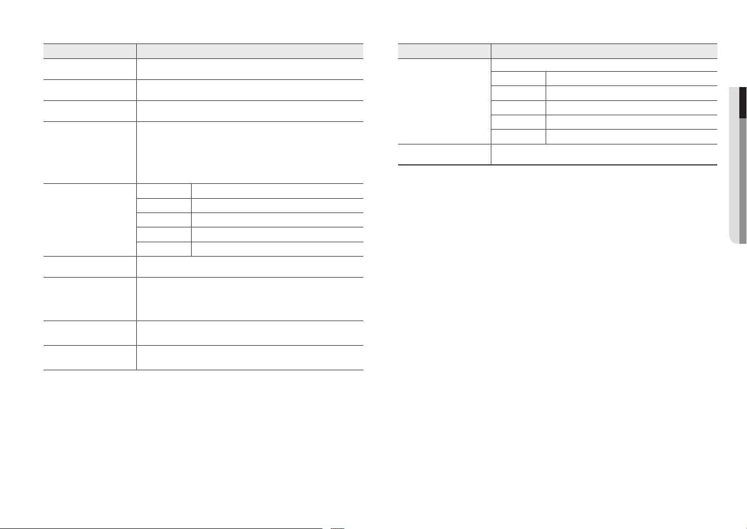
NAS RECOMMENDED SPECS
• Recommended capacity : 200GB or higher is recommended.
• Simultaneous access : One unit of NAS can accept a maximum of sixteen camera accesses.
• For this camera, you are recommended to use a NAS with the following manufacturer’s specs.
Recommended products Available sizes
QNAP NAS A maximum of 16 cameras can access simultaneously.
Synology NAS A maximum of 16 cameras can access simultaneously.
If you use NAS equipment for purposes other than video saving, the number of accessible cameras may be reduced.
`
J
6_ overview

WHAT’S INCLUDED
Please check if your camera and accessories are all included in the product package.
(As for each sales country, accessories are not the same.)
Appearance Item Name Quantity Description
Camera
1
Appearance Item Name Quantity Description
Star-shaped wrench
CAUTION: Be ware of the
Rated Voltage and Polarity
of the power connection.
Power Cable
1
1
Used to remove and replace the dome cover
Used to plug into the power port
●● OVERVIEW
Instruction book,
Installer S/W CD
Quick Guide
(Optional)
Warranty card
(Optional)
Cable for the testing monitor
Mount plate
Power Terminal Block
1
1
1
Used to test the camera connection to a portable
1
1
1
display device
Product installation guide
Plugged in the power plug
Tapping Screw 4 Used for installation on the wall or ceiling
Audio/alarm cable
Cable bush
Plastic Anchor
Machine Screws
Card-type moisture absorbent
1
Used to connect with the audio and alarm port
1
4
3
1
Common bushings for all cables
For fixing a screw, Inserted in a hole
(reinforced anchoring force)
Used for assembling the dome case when installing the
product on the pipe, wall mount, etc. or blocking a hole.
Attached when installed.
Cap Installer 1 Used when connecting RJ45 cable
English _7
overview
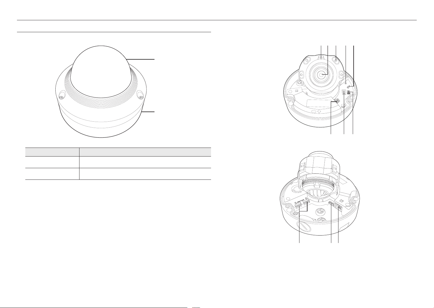
AT A GLANCE (XNV-6080RS/XNV-8080RS)
Appearance
Item Description
a
b
Dome cover
Camera Case
Case cover used to protect the lens and the main unit.
Housing part that covers the camera body.
a
b
Components
a c d eb
RESET
AF
F
F
T
NETWORK
ALARM
AUDIO
ACT
LINK
W
N
USB
VIDEO
AC 24V
DC 12V
f g h
AUDIO
ALARM
1
2
ACT
NETWORK
LINK
8_ overview
i kj

Item Description
Illumination Sensor Detects incoming light to control the IR LED.
a
Lens Lens for the camera.
b
IR LED These infrared LED’s are controlled by the illumination sensor.
c
The button restores all camera settings to the factory default.
Press and hold for about 5 seconds to reboot the system.
If you reset the camera, the network settings will be adjusted so that DHCP can be
Reset Button
d
Zoom/Focus Control Button
e
Power Port Port for power terminal block.
f
MICRO USB port
g
Test Monitor Out
h
Micro SD Memory Card
i
Compartment
J
enabled. If there is no DHCP server in the network, you must run the IP Installer
program to change the basic network settings such as IP address, Subnet mask,
Gateway, etc., before you can connect to the network.
T Zoom in (Tele)
W Zoom out (Wide)
N Focusing on a near object (Near)
F Focusing on a far object (Far)
Focus Control Press this button for automatic focus control.
Port to connect the Wi-Fi dongle.
You can check the installation video through the applications installed in the smartphone.
Refer to “Connect to WiFi dongle” on page 16.
WiFi dongle and OTG adapter are sold separately.
`
Output port for test monitoring the video output. Use the test monitor cable to connect to a
mobile display and check the test video.
Compartment for the Micro SD memory card.
Item Description
Port to connect audio and alarm cables.
ARM-IN Used to connect the alarm input sensor or external day/night sensor.
Audio and alarm cable port
j
Network Port Used to connect the PoE or Ethernet cable for network connection.
k
ARM-OUT Used to connect the alarm output signal.
GND These are common ports to connect alarm input/output signals.
MIC Used to connect to a microphone.
SPEAKER Used to connect to speakers.
●● OVERVIEW
English _9
overview
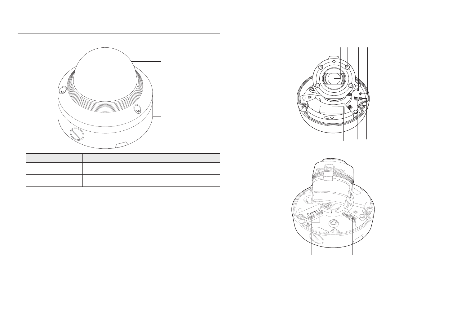
AT A GLANCE (XNV-6120RS)
Appearance
Item Description
a
b
Dome cover
Camera Case
Case cover used to protect the lens and the main unit.
Housing part that covers the camera body.
a
b
Components
a c d eb
RESET
AF
F
F
T
NETWORK
ALARM
AUDIO
ACT
LINK
W
N
USB
VIDEO
AC 24V
DC 12V
f g h
AUDIO
ALARM
1
2
ACT
NETWORK
LINK
10_ overview
i kj
Item Description
Illumination Sensor Detects incoming light to control the IR LED.
a
Lens Lens for the camera.
b
IR LED These infrared LED’s are controlled by the illumination sensor.
c
The button restores all camera settings to the factory default.
Press and hold for about 5 seconds to reboot the system.
If you reset the camera, the network settings will be adjusted so that DHCP can be
Reset Button
d
Zoom/Focus Control Button
e
Power Port Port for power terminal block.
f
MICRO USB port
g
Test Monitor Out
h
Micro SD Memory Card
i
Compartment
J
enabled. If there is no DHCP server in the network, you must run the IP Installer
program to change the basic network settings such as IP address, Subnet mask,
Gateway, etc., before you can connect to the network.
T Zoom in (Tele)
W Zoom out (Wide)
N Focusing on a near object (Near)
F Focusing on a far object (Far)
Focus Control Press this button for automatic focus control.
Port to connect the Wi-Fi dongle.
You can check the installation video through the applications installed in the smartphone.
Refer to “Connect to WiFi dongle” on page 16.
WiFi dongle and OTG adapter are sold separately.
`
Output port for test monitoring the video output. Use the test monitor cable to connect to a
mobile display and check the test video.
Compartment for the Micro SD memory card.
Item Description
Port to connect audio and alarm cables.
ARM-IN Used to connect the alarm input sensor or external day/night sensor.
Audio and alarm cable port
j
Network Port Used to connect the PoE or Ethernet cable for network connection.
k
ARM-OUT Used to connect the alarm output signal.
GND These are common ports to connect alarm input/output signals.
MIC Used to connect to a microphone.
SPEAKER Used to connect to speakers.
●● OVERVIEW
English _11
installation & connection
installation & connection
INSTALLATION
This camera is waterproof and in compliance with the IP66 spec, but the jack connected to the external cable is not. You are
`
J
recommended to install this product below the edge of eaves to prevent the cable from being externally exposed.
Precautions before installation
Ensure you read out the following instructions before installing the camera:
• It must be installed on the area (ceiling or wall) that can withstand 5 times the weight of the camera
including the installation bracket.
• Stuck-in or peeled-off cables can cause damage to the product or a fire.
• For safety purposes, keep anyone else away from the installation site.
And put aside personal belongings from the site, just in case.
• If excessive force is used while installing the product, the camera may be damaged due to malfunction.
Forcing assembly using non-compliant tools may damage the product.
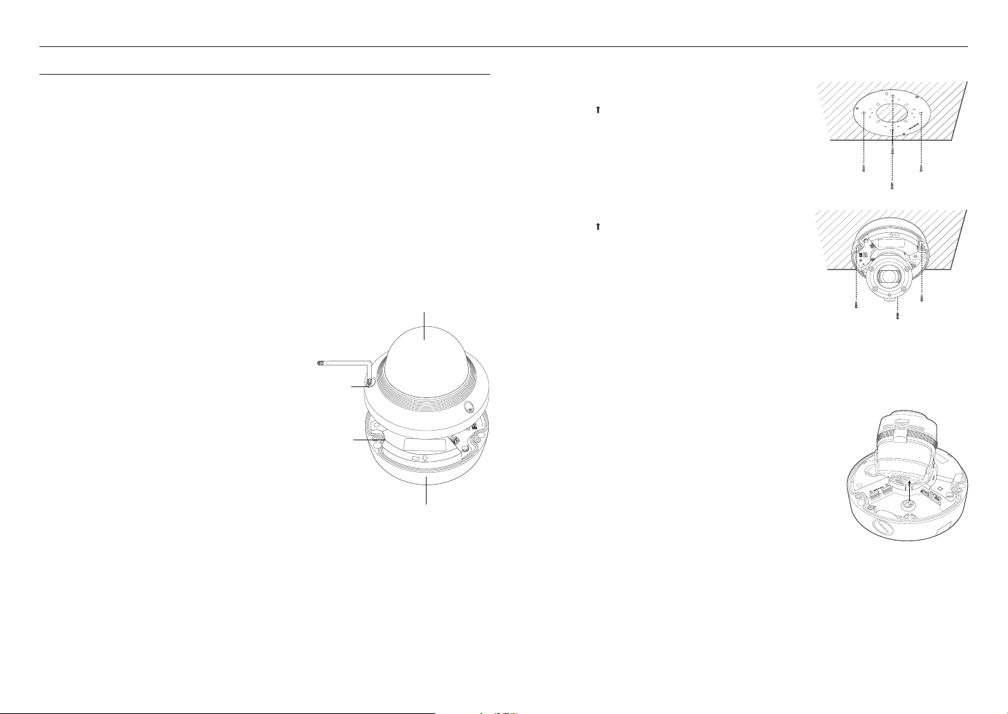
Disassembling
1. Use the supplied star-shaped wrench to loosen
the dome cover fastening bolt by turning it in a
counterclockwise direction, and remove the dome cover.
Bolts
Camera Body
NETWORK
ACT
LINK
Dome cover
ALARM
AUDIO
Installation
1. Drill holes to fit the four D points of the mounting plate provided as
an accessory.
`Orient the [
] mark toward the direction you want to monitor.
2. Fully insert the plastic anchor.
3. Align the mounting hole of the camera with the hole where the
plastic anchor is inserted, then tighten the tapping screw.
4. Tighten the mount plate and camera case as shown.
`Orient the [
5. Connect and arrange the necessary cables lest that they should
be damaged or twisted while installing the camera.
] mark toward the direction you want to monitor.
DC 12V
AC 24V
VIDEO
USB
N
W
T
F
F
AF
RESET
LINK
ACT
AUDIO
ALARM
NETWORK
6. Adjust the lens in a desired direction by referring to the “Adjusting
the monitoring direction for the camera” section. (page 15)
7. Close the dome cover.
`Securely fasten the fastening bolt using an L wrench to prevent water from
leaking.
Connecting waterproof power cable and LAN cable
RESET
AF
F
F
T
W
N
USB
VIDEO
AC 24V
DC 12V
1. Remove the dome cover and the case.
2. Pull out the long projected part of the rubber plug on the bottom and
remove it as shown in the figure.
12_ installation & connection
Camera Case
AUDIO
ALARM
1
2
NETWORK
ACT
LINK
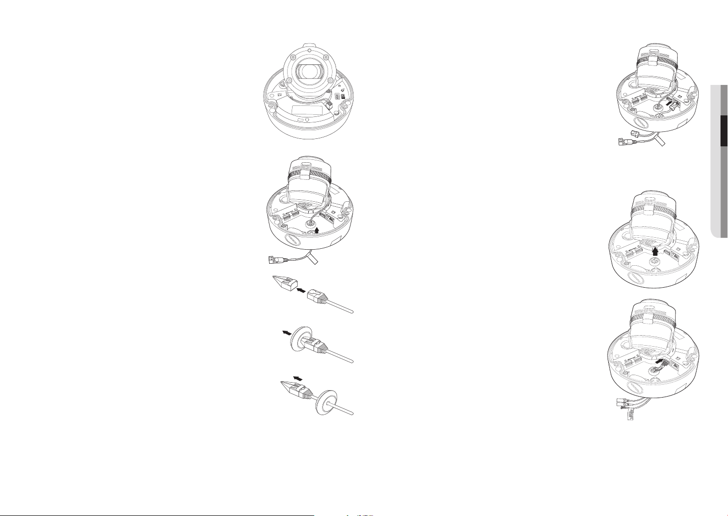
3. Insert the power cable into the small hole made by removing the
projected part of the rubber plug in step 2 above, and lay the cable along
the long groove.
4. Connect the power cable with the power terminal block.
7. Insert the rubber stopper again and connect the LAN cable to the Ethernet
terminal.
RESET
AF
F
F
T
NETWORK
ALARM
AUDIO
ACT
LINK
W
N
USB
VIDEO
AC 24V
DC 12V
2
AUDIO
ALARM
1
ACT
LINK
NETWORK
CAUTION: Be ware of the
Rated Voltage and Po larity
of the power connec tion.
●● INSTALLATION & CONNECTION
5. Pull out the rubber stopper on the floor as shown.
6. Use the Cap Installer to allow the RJ45 cable to pass through.
Connecting the alarm and audio cable
1. Remove the dome cover and the case.
2. Pull out the rubber plug on the bottom as shown in the figure.
AUDIO
ALARM
1
2
ACT
LINK
NETWORK
AUDIO
ALARM
1
CAUTION: Be ware of the
Rated Voltage and P olarit y
of the power conne ction.
2
NETWORK
ACT
LINK
3. Insert the alarm/audio cable through the hole created by removing the
rubber cap in No. 2, and connect the cable to the alarm terminal.
4. Align the cable so that it should not be damaged or jammed when
installing the camera.
5. Put the rubber cap located on the alarm/audio cable in the hole.
AUDIO
6. Adjust the lens in a desired direction by referring to the “Adjusting the
monitoring direction for the camera” section.
(page 15)
1
2
ALARM
ACT
LINK
NETWORK
7. Attach the dome cover.
English _13
installation & connection
Attaching to the unbundled adapter
Choose and purchase a necessary one of the following options (unbundled) that is suitable to the installation
site or for your convenience.
1. Remove the dome cover from the case by referring to the “Disassembling” section. (page
2. Use the provided machine screw to fix the camera case to the unbundled adapter.
3. Connect and arrange the necessary cables lest that they should be damaged or twisted while installing the
camera.
4. Install the camera body in the reverse order of “Disassembling”.
5. Adjust the lens in a desired direction by referring to the “Adjusting the monitoring direction for the
camera” section. (page
6. Close the dome cover.
`Tighten the fastening bolts tightly using the star-shaped wrench to prevent water leakage.
15
)
12
)
Outdoor installation
When you install it outside of the building, please waterproof it with waterproof butyl rubber tape (can be
purchased in stores) so that water does not leak from the gap of the cable connected to the outside.
1. Connect the power, I/O, BNC, and LAN cables.
2. Wrap the black cable jacket (Area A) and the cable connection area
with waterproof (butyl rubber) tape so that more than half of the
butyl rubber tape is overlapped.
If the cable jacket is not waterproofed properly, then it can directly cause
`
J
leakage. Make sure to protect the cable with a dense layer of taping.
Waterproof butyl tape is made of butyl rubber that can be stretched to twice
`
its normal length.
Camera
Camera
Camera
System
System
AA
System
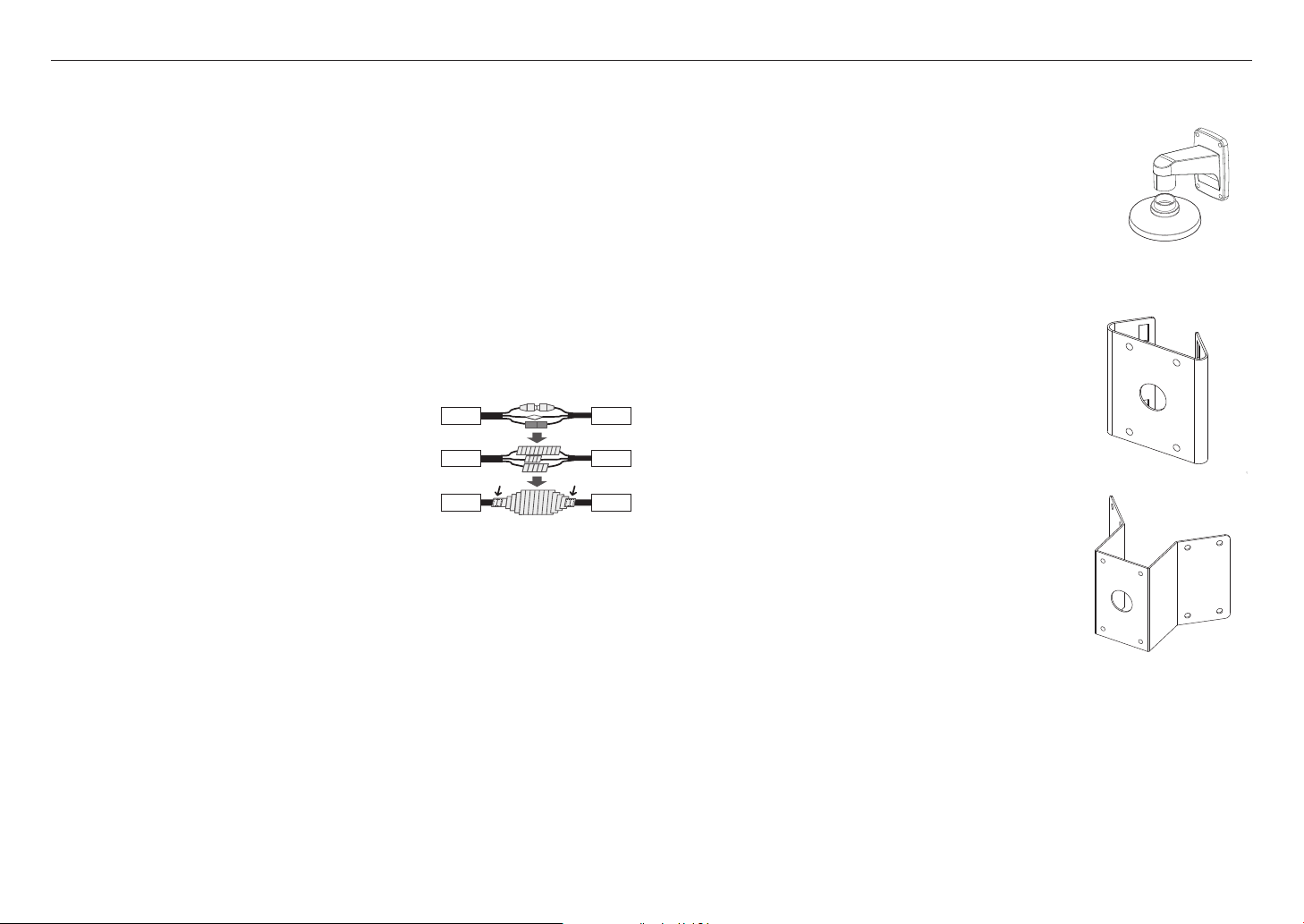
Optional Accessories for Installation
For your easier installation, you can purchase appropriate optional accessories available.
1. FRAME MOUNT(SBP-300WMS)/HANGING MOUNT(SBP-HMS6)
This adaptor is used when installing the dome camera onto a wall.
2. POLE MOUNT ADAPTOR(SBP-300PMS)
This is an adaptor for WALL MOUNT ADAPTOR (SBP-300WMS or SBP300WMS1) installation on a pole whose diameter is bigger than 80mm.
3. CORNER MOUNT ADAPTOR (SBP-300KMS)
This is an adaptor for WALL MOUNT ADAPTOR (SBP-300WMS or
SBP-300WMS1) installation on the corner of wall joint.
14_ installation & connection
 Loading...