

Page 1
Training Manual
Washing Machine (Drum Type) ※ Basic :WF455ARG***
The Largest Capacity
Smart Care
Power Foam™
Speed Spray
VRT plus™
Deep Steam
Pure Cycle™
Stylish Design
Diamond Drum™
DD Motor
WF45H6***
WF42H5***
0
Page 2

Contents
Contents
Contents
1.
1.
2.
2.
3.
3.
4.
4.
5.
5.
6.
6.
7.
7.
Product Introduction ………...……………..…….…… 3
Product Introduction
Changed Part List ………...……………..…….…….… 9
Changed Part List
Disassembly and Reassembly ………...…………….… 20
Disassembly and Reassembly
Instruction of Function ………...……………………… 31
Instruction of Function
Test Mode
Test Mode
PCB Diagram ………...…………………….……..…… 50
PCB Diagram
Reference Information ………...…………….…..…… 54
Reference Information
&
Error Check ………...……………..…… 34
&
Error Check
1/54
Page 3
1. Product Introduction
WF5000H Potomac
Main
Spec
Target
Performa
nce
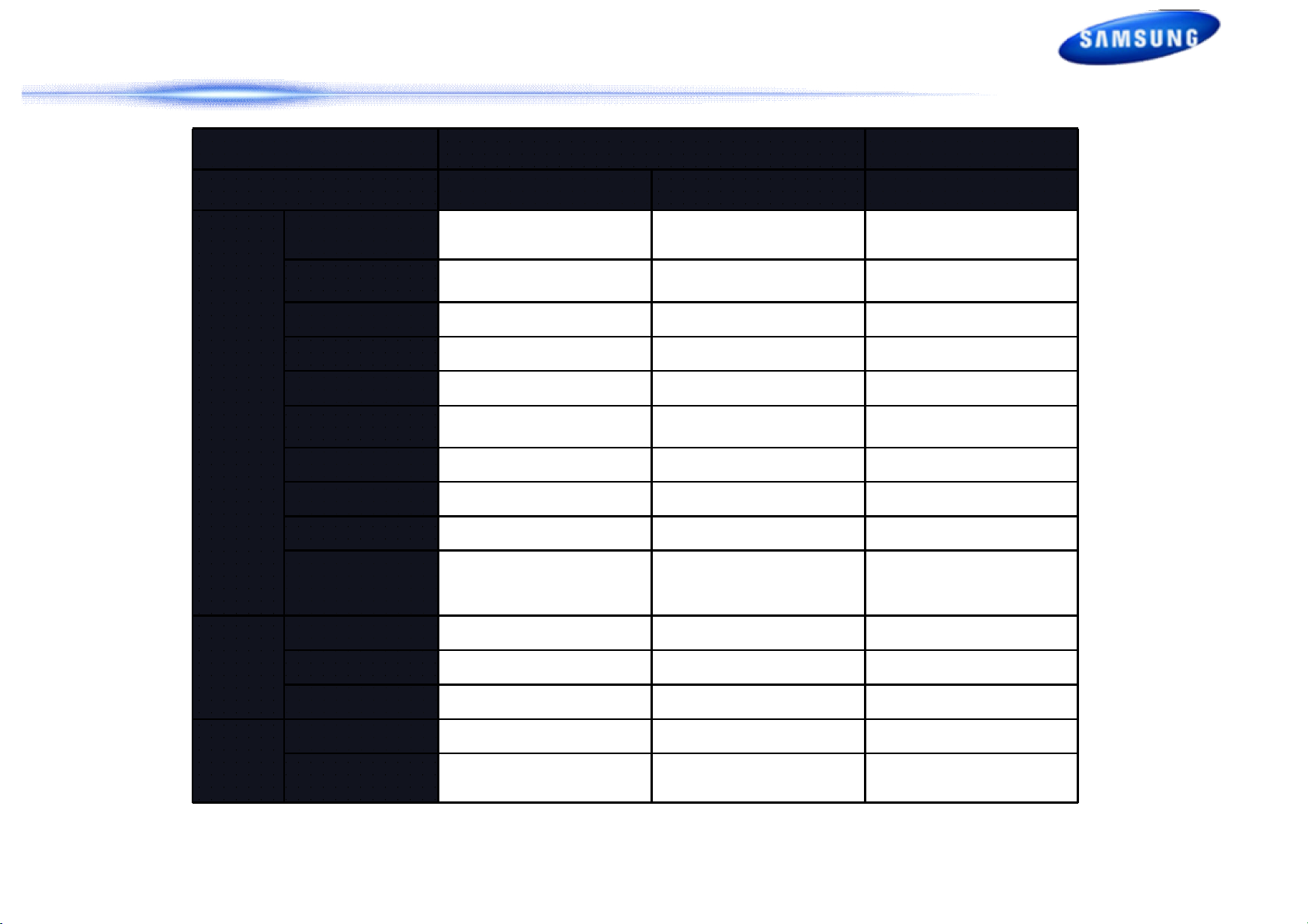
Category WF42H5700*** WF42H5200***
Capacity (cu.ft.
IEC)
Motor type DD Motor DD Motor DD Motor
MAX RPM 1200 1200 1300
VRT Yes (VRT+) Yes (VRT+) Yes (VRT+)
Heater (900W) Yes Yes Yes
Diamond Drum Yes Yes Yes
Washing Cycle # 13 13 13
Delay Wash 24 hrs 24 hrs 24 hrs
Tilted Drum 10° 10° 10°
(Sound Levels) Ave 58dBA↓ Ave 58dBA↓ Ave 56.3dBA↓
MEF 3.2 3.2 3.2
WCF 2.9 2.9 2.99
kWh/year 93 kWh/year 93 kWh/year 95 kWh/year
4.2cu.ft 4.2cu.ft 4.5cu.ft
WF455ARG***
Design
Control Display LED LED G.LED
Dimension
(W*D*H)
27.0X 32.3X 38.7" 27.0X 32.3X 38.7" 27 X 32.3 X 38.7"
2/54
Page 4

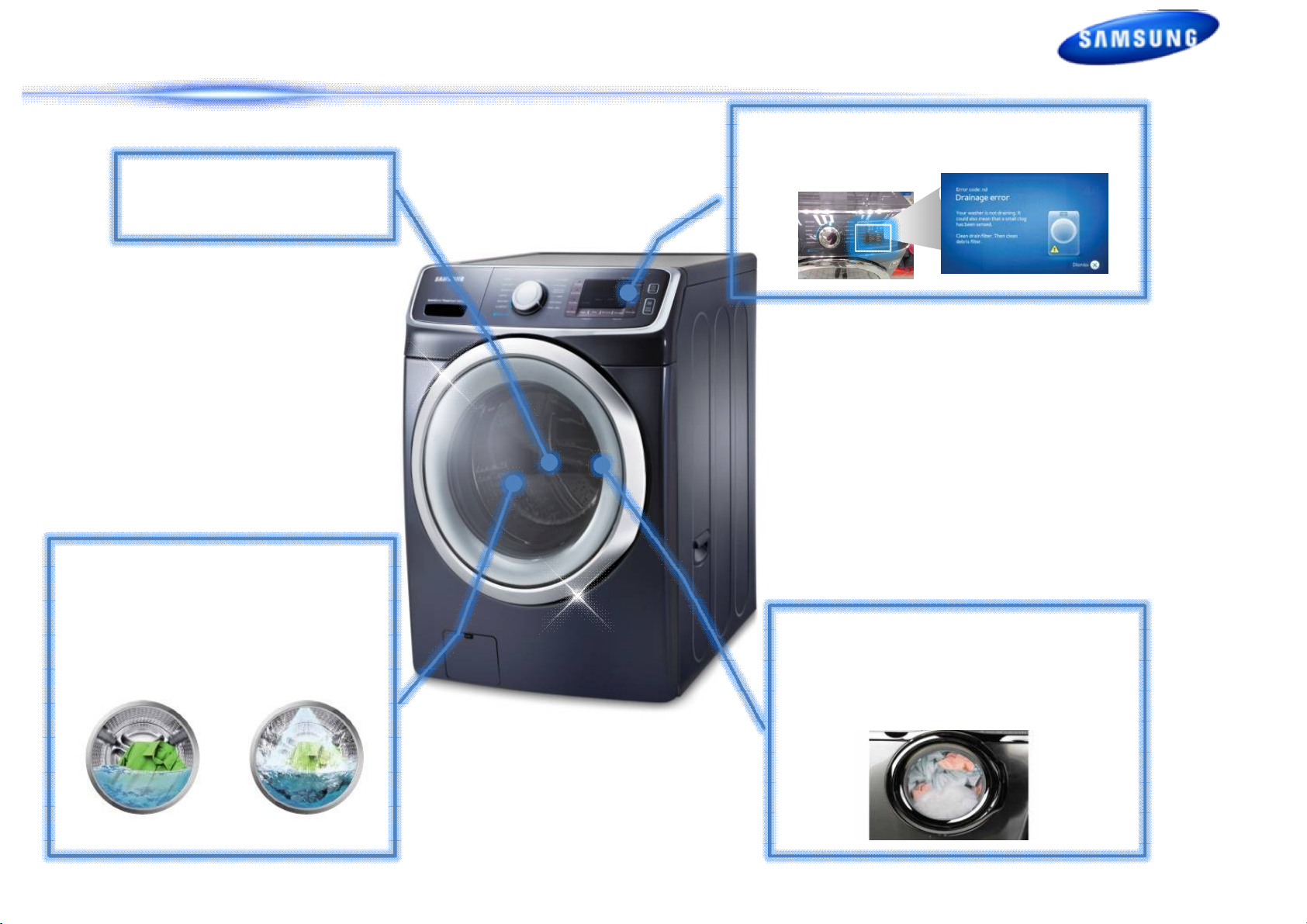
1. Product Introduction : WF6000H / WF5000H
The Leader of Premium Laundry with Utmost Smart Features
Key Features
• Washer 4.5cu.ft. / 4.2cu.ft
• Smart Care
• Smart-Grid Ready
• SpeedSpray
• PowerFoam™
• Steam clean (Wash)
Energy Performance
• Most Efficient
• CEE Tier 3
Launch
• Dec 2013
3/54
Page 5
1. Product Introduction : Key Features
Smart Care
4.2cu.ft.
Large Capacity
SpeedSpray
technology
• 25% Shorter Cycle Time
• Faster Washing with
• Self-Diagnosis
PowerFoam technology
Quality Cleaning
Conventional
• Detergent penetrates more
quickly and evenly on big loads
SpeedSpray
4/54
Page 6

1. Product Introduction : New Feature | SpeedSpray
5/54
Page 7

1. Product Introduction : New Feature | SpeedSpray
Spend less time doing more laundry
“Introducing Samsung’s new SpeedSpray technology reduces cycle time by
25% vs. conventional machines”
New Speed Spray technology provides shooting a powerful
-25%
jet of water into clothes, speeds up the time it takes for the
washing and rinsing and reduces overall cycle time by 25% vs.
conventional washers* (Normal Cycle 60 min to 45 min).
*Based on 8 pounds loads, Normal cycle, on previous and existing 4.3 cu.ft. Samsung front loading
washers released until 2011 without SpeedSpray.
[Washing Process] [Rinsing Process]
Conventional
*Images : Not final version. Work in progress.
SpeedSpray
Conventional
SpeedSpray
6/54
Page 8
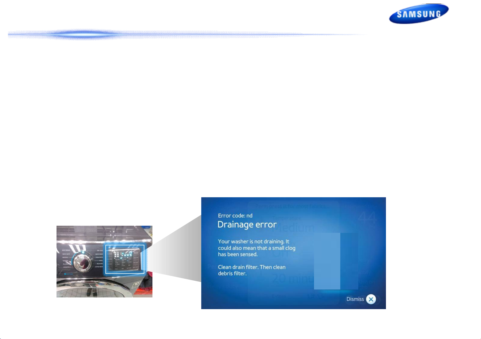
1. Product Introduction : New Feature | Smart Care
Quick & easy solution for your problem
“Self-Diagnosis give s quick & easy solution, no need to call a repairman
whenever you have a problem with the machine.”
Smart Care, an automatic error-monitoring system, detects and diagnoses
problems at an early stage and provides a quick and easy solution through LCD
navigation. With the innovative Smart Control technology, you can also be alerted
when the problem occurs via your smart phones.
*Images : Not final version. Work in progress.
7/54
Page 9
2. 변경점 List
2. Changed Part List
Part
Assy
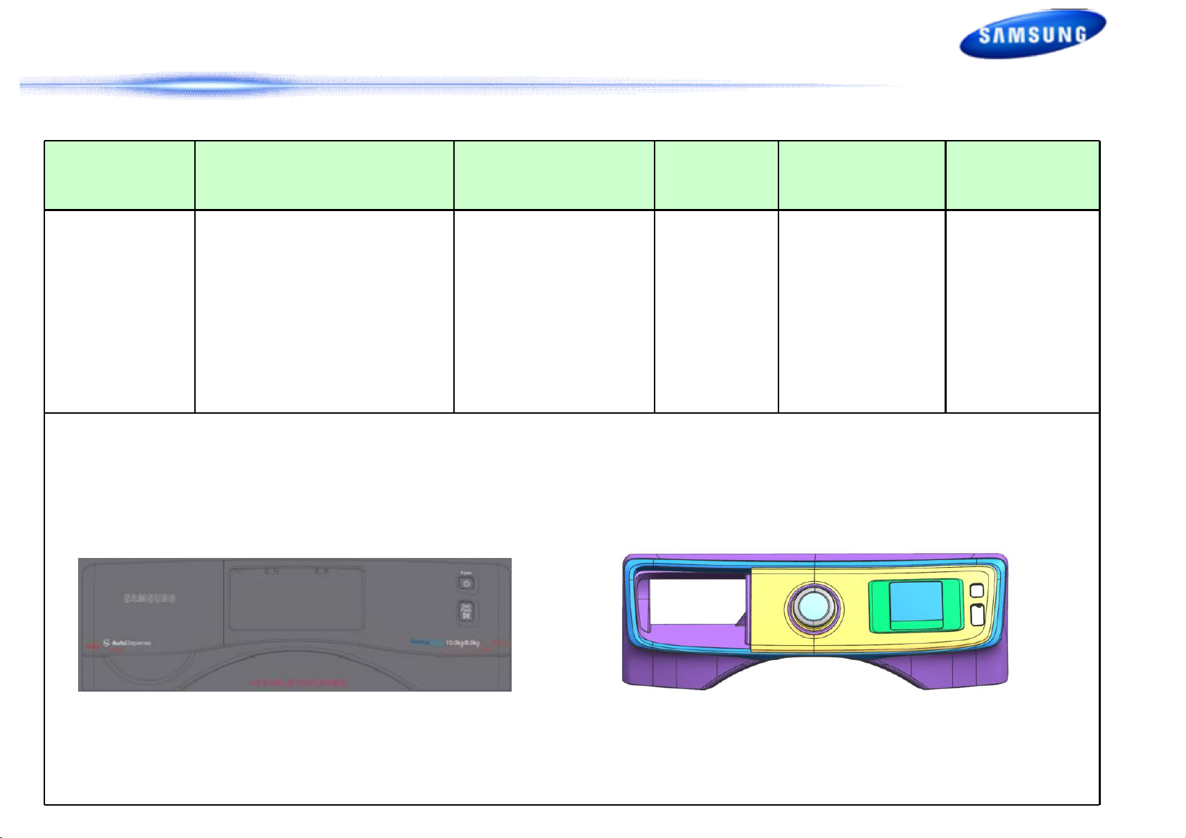
Panel Control
[Best]
Basic Model
[WF455AR]
-Button, Jog Dial Type
-Button : Rubber Button type
WF6000H/WF5000H
[WF]
-Button type
Cause
Changes
- Design
- USP
RISK Test
- Touch Malfuction
- Button Malfuction
- Water
- Button Durability
<Basic Model>
8” Touch LCD
<WF6000H/WF5000
H>
8/54
Page 10
2. 변경점 List
2. Changed Part List
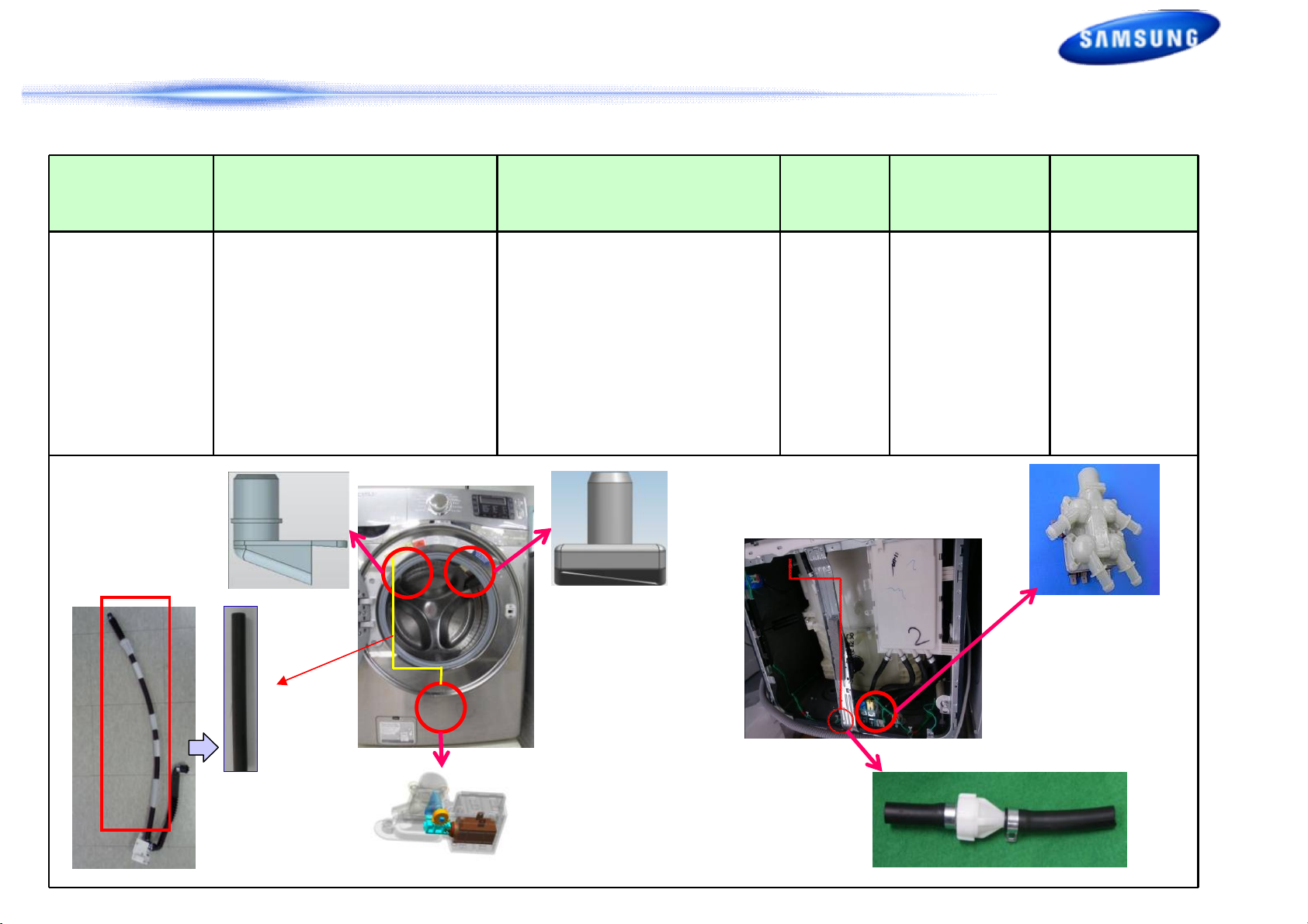
Part
2nd
Bubble
Shot
Basic Model
[WF455AR]
-3 way Water Valve
-Bubble kit
WF6000H
[WF]
- Nozzle, Connecting Hose
- Water Inverter Valve
- 4 way Water Valve
- Diaphragm Nozzle Insert
- Hose/Frame Support Structure
- Reflux Preventing Nozzle
Change
Cause
- USP
RISK Test
-Performance
-Water Intrusion
-Noise
-Performance
-Real using
-Noise
<Grace S>
9/54
Page 11
2. 변경점 List
2. Changed Part List
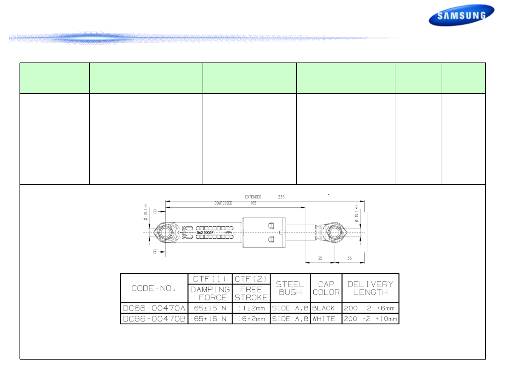
Part
Damper
Basic Model
[WF455AR]
- DC66-00470A 4ea
Free-stroke 4mm
WF6000H/WF5000H
[WF]
- DC66-00470A Front 2ea
Free-stroke 4mm
- DC66-00470B Rear 2ea
Free-stroke 8mm
Change Cause RISK Test
- Increased Floor Vibration
- For Acquiring CU Vibration
Rate Excellent
- Vibration
- Noise
-Actual Use
-Noise
10/54
Page 12
2. 변경점 List
2. Changed Part List
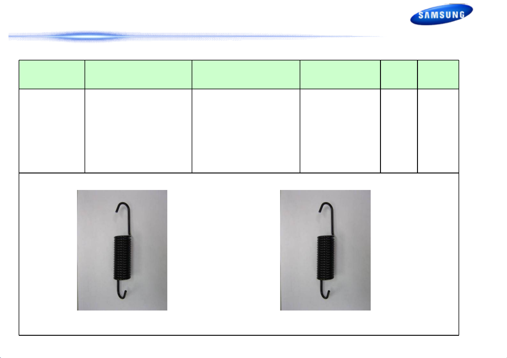
Part
Spring
Basic Model
[WF455AR]
- DC61-01257E
Stiffness : 0.92 kgf/mm
Free Length : 183 mm
Initial Force(@20mm)
: 11.6 kgf (30 kgf)
WF6000H/WF5000H
[WF]
Stiffness: 1.20 kgf/mm
Free Length : 182 mm
Initial force (@20mm)
: 5.0 kgf (29 kgf)
Change Cause RISK Test
- Exp,Dom Common Use
- Noise
- Modified Free Length
- Noise
- Vibration
- Noise
- Actual Use
<Basic Model> <WF6000H>
11/54
Page 13
nd
2
2. Changed Part List
Bubble Shot 기구 구성
Part List
1
3
2
4
Part
1
4 Way Valve
2
3
4 Reflux Preventing Valve
5 Nozzle 1st Bubble Shot
6 Nozzle 2nd Bubble Shot
Direct Hose
Assy’ Hose Connector
5
6
Diaphragm
12/54
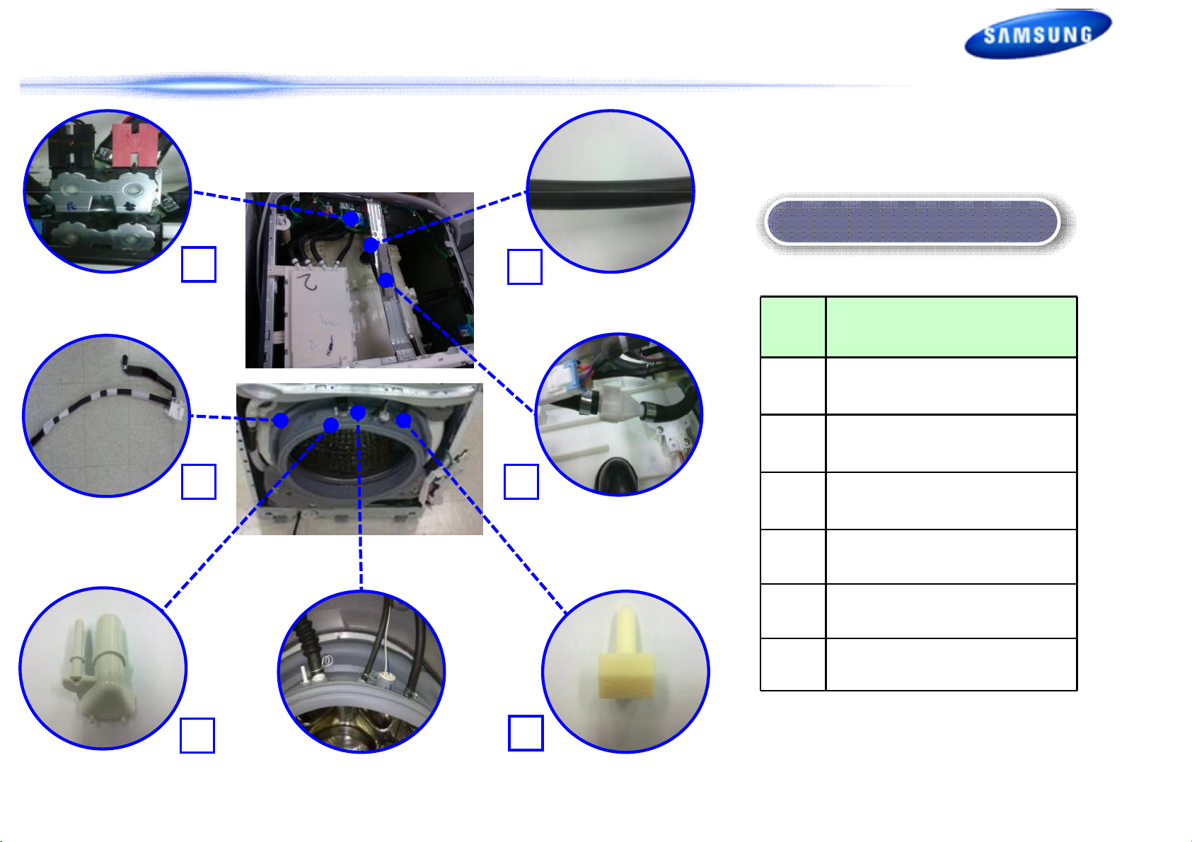
Page 14
2. 변경점 List
2. Changed Part List
Assy Tub Change List
Exploded
View
Basic Model
[WF455AR]
WF6000H/WF5000H
[WF]
15
No Part Usage Remark
Change Parts
14
1 Door Diaphragm
13
12
11
10
9
8
7
2 Weight Balancer
3 Assy Heater
4 Damper
5 Tub Front
6 Hose Joint Air
7 Hose Drain
8 Packing Tub
9 Damper
Common
Common
Common
Common
Common
Common
Common
Common
Common
GRACE
GRACE
GRACE
GRACE
GRACE
GRACE
GRACE
GRACE
GRACE
6
5
4
3
2
1
10 Tub Back
11 Hose O.F
12 Housing Bearing
13 Bracket Tub
14 Motor
15 MEMS sensor
Common
Common
Common
Common
Common
Common
GRACE
GRACE
GRACE
GRACE
GRACE
Cost Reduction
13/54
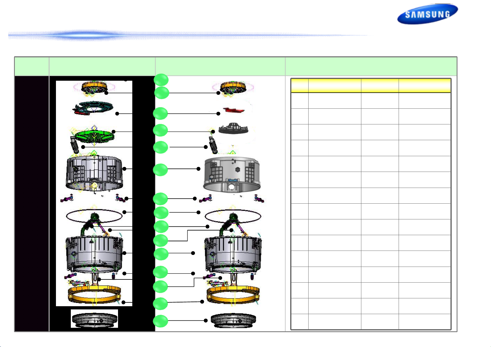
Page 15
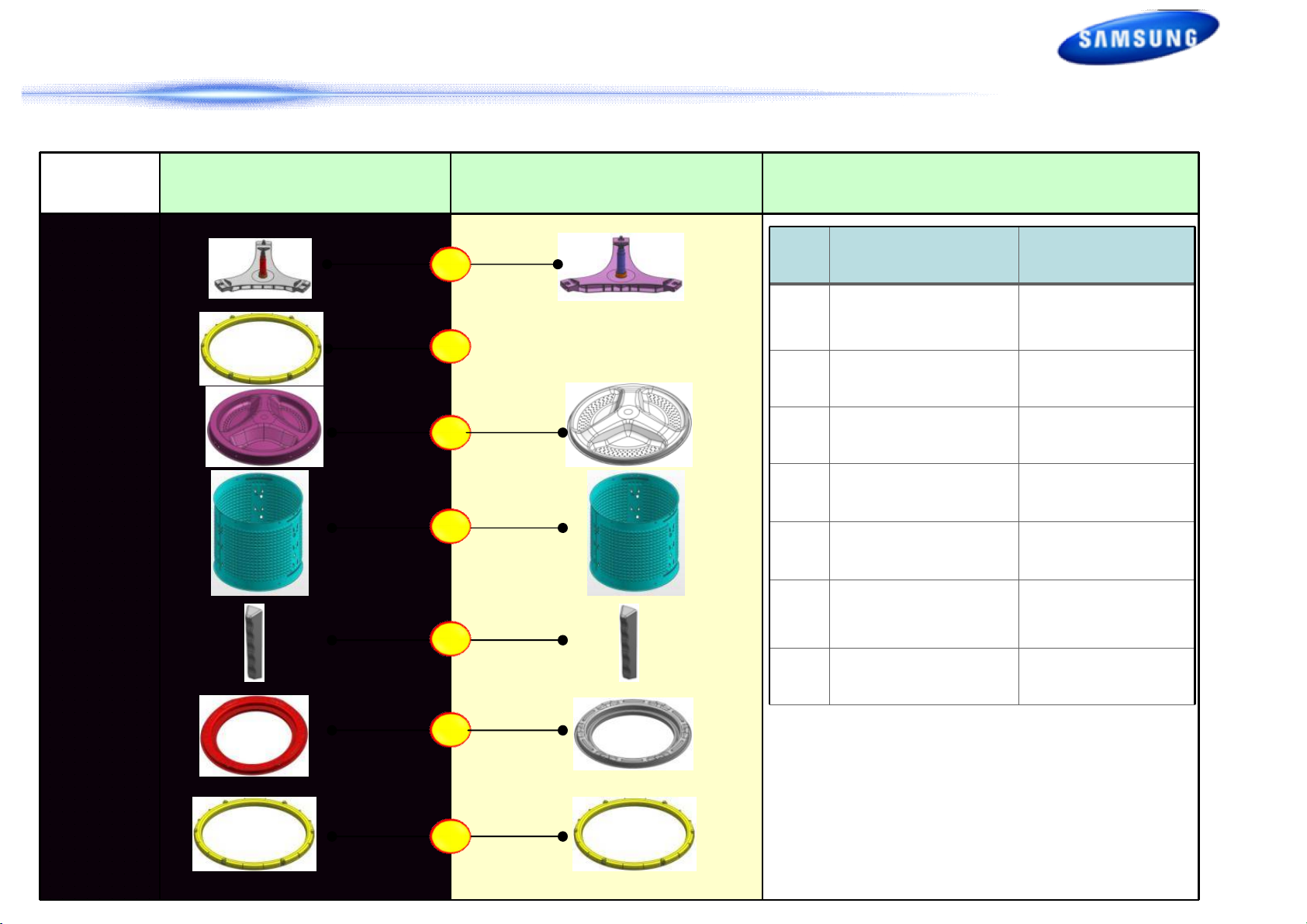
2. 변경점 List
2. Changed Part List
Assy Drum Change List
Exploded
View
Basic Model
[WF455AR]
WF6000H/WF5000H
[WF]
1
2
3
4
5
No. Part
1
2
3 Drum-Back Common
4 Drum-Wrapper Common
5 Drum-Lifter Common
6 Drum-Front Common
Assy-Balance
Changed Parts
Assy-F/Shaft
(Ring-OG)
(Rear)
Cause
Change
Common
Common
6
7
7
Assy-Balance
(Front)
Common
14/54
Page 16
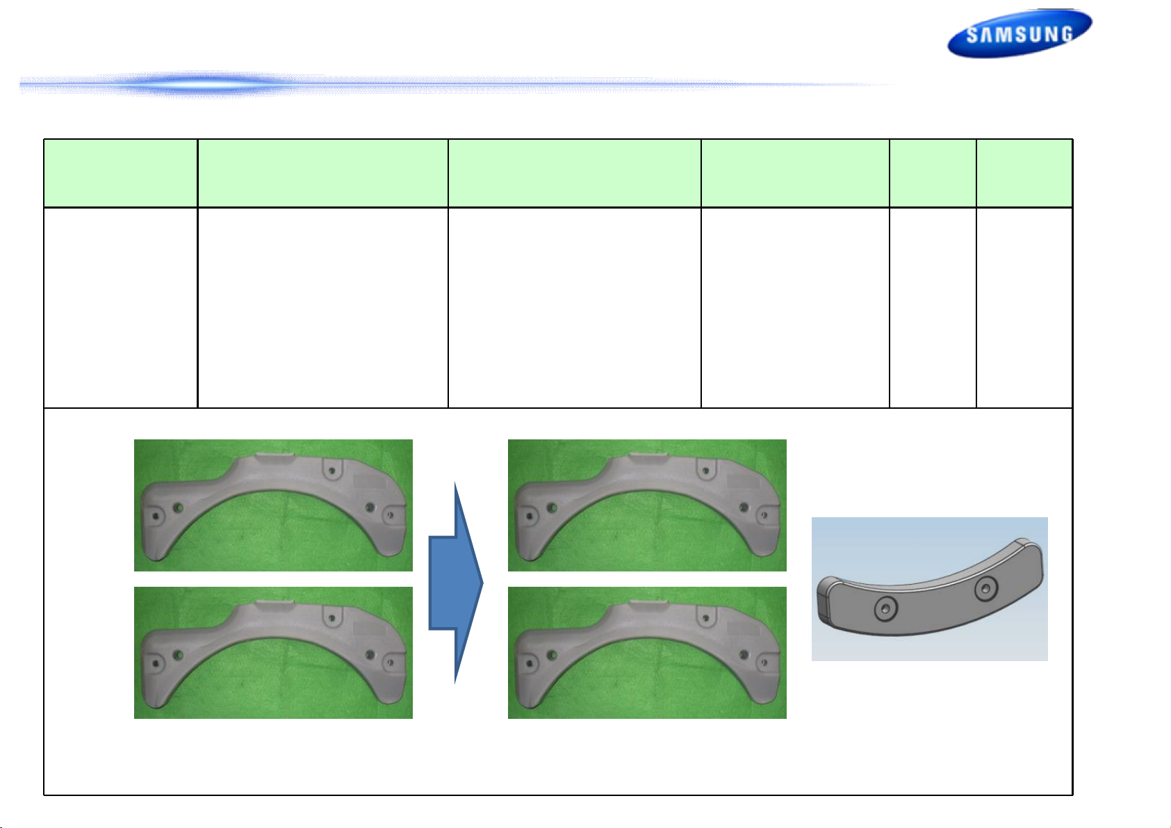
2. 변경점 List
2. Changed Part List
Part
Weight-Balance - 9.6kg*2 - 9.6kg*2 + 3kg*1
Basic Model
[WF455AR]
WF6000H/WF5000H
[WF]
Change Cause RISK Test
- Recovering Weight due
to Delete of Rear
B/Balance
<Basic Model> <WF6000H/WF5000
H>
Weight-Balance(R)
15/54
Page 17
2. 변경점 List
2. Changed Part List
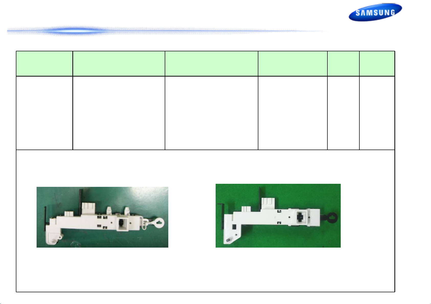
Part
Door-Lock S/W - EMZ - Dual-Mecha - Cost Reduction
Basic Model
[WF455AR]
WF6000H/WF5000H
[WF]
Change Cause RISK Test
<Basic Model> <WF6000H/WF5000H>
16/54
Page 18

2. 변경점 List
2. Changed Part List
Part
ASSY PCB MAIN
Basic Model
[WF455AR]
- Main PBA
- 2XSMPS,0.45W
- Renesas 32bit/256k Micom
- Sanyo 10A Dip IPM
-Display PBA
- Renesas 16bit/160k Micom
- 3.5inch Dot LCD
WF6000H/WF5000H
[WF]
- Main PBA
- 1XSMPS,0.45W
- Toshiba 32bit/512k Mi-com
- LSPS 15A Dip IPM
-Display PBA(Better/Good LED)
- Free scale 8bit/64k Mi-com
- Dot LED
-Sensor PBA(Best LCD)
- Free scale 8bit/64k Mi-com
- Power On/OFF Switch
- Start/Stop Switch
- Water Level, Temp. Sensor
Change Cause RISK Test
-Main PBA
- Cost Reduction
(SMPS,IPM)
- Upgrade
Mi-com ROM
-LED PBA
- Design
-LCD PBA
- Product Requirement
-Sensor PBA
- LCD PBA
Durability
Electronic St
ress
Thermal
Stress
Environment
PBA HALT
PBA ALT
SLT,SLAT
Stress
Analysis
(Main PBA)
(Display PBA)
(Best)->
Main PBA
+
(New)
+
(Better/Good)->
<Basic Model> <WF6000H/WF5000H>
Sensor
PBA
(New)
Display PBA
LED+ENCORDER
(New)
17/54
Page 19

2. 변경점 List
2. Changed Part List
Part
ASSY M. Guide Wire
Harness
Basic Model
[WF455AR]
- PCB Location : SET Right Up - PCB Location : ARNO TYPE
- BOTTOM WIRE Holder Deleted
- Added Function : SMART GRID
WF6000H/WF5000H
[WF]
Change Cause RISK Test
- PCB 위치 변경
- Layout Changed
- Manufacture
- Assembly
- EMI
- Noise,
Vibration
<Basic Model> <WF6000H/WF5000H>
18/54
Page 20

3. Disassembly and Reassembly
3-1. Tools for disassembly and reassembly
Tool Type Remarks
Socket Wrench with
6” Extension
Open End wrench
10mm 13mm 19mm
10mm 13mm 19mm
Heater(1) Motor(1), Balance(5), 2holes
of each left and right of the shock
absorber 1 Pulley hole
Replace able for the box driver.
Since the bolt runs idle when the box
driver isused, use the box driver 17mm.
Tool to protect the idle and abrasion of
Vice pliers
(Driver,Nipper,Longnose)
Others
JIG for the Tub
the bolt for the box driver.
General tools for the after service.
1 (Disassemble and Assemble)
19/54
Page 21

3. Disassembly and Reassembly
3-2. Standard disassembly drawings
► This is a standard disassembly diagram and may differ from the actual product.Use this material as a reference
when disassembling and reassembling the product.
Part
ASSY COVER TOP
Figure
1. Remove the two screws holding the Top Cover at the back of the
unit.
2. Remove the top-cover by lifting it up after pulling it back about
15mm.
Description
3. With the top cover removed you will now have access to service
the Water pressure sensor, EMI Noise Filter, Hot and Cold Water
Valves, Hose Draw ASSY.
20/54
Page 22

3. Disassembly and Reassembly
3-2. Standard disassembly drawings
► This is a standard disassembly diagram and may differ from the actual product.Use this material as a reference
when disassembling and reassembling the product.
Part Figure Description
1. Remove the 2 screws at the top of the ASSY-PANEL CONTROL.
2. Hold the ASSY-PANEL CONTROL while pulling it upwards and
release the hook to remove it.
MAIN-PCB AND
SUB-PCB PANEL
3. Carefully disconnect the two wiring connectors by hand.
4. Remove the 8 screws holding the PCB and release the hooks on
both sides to remove the PCB for repair / replacement.
21/54
Page 23

3. Disassembly and Reassembly
3-2. Standard disassembly drawings
► This is a standard disassembly diagram and may differ from the actual product.Use this material as a reference
when disassembling and reassembling the product.
Part Figure Description
• Seperate the Wire-Diaphragm with the Long-nose from the FrontFrame.
1. Remove the Diaphragm.
FRAME FRONT
2. Remove the 4 screws holding the FRAME-FRONT.
3. Remove the 2 screws holding the bottom of the FRAME-FRONT.
22/54
Page 24

3. Disassembly and Reassembly
3-2. Standard disassembly drawings
► This is a standard disassembly diagram and may differ from the actual product.Use this material as a reference
when disassembling and reassembling the product.
Part Figure Description
4. Untie the hose.
5. Remove the 3 screws.
FRAME FRONT
6. Push the hook.
7. Disconnect the terminal for the DOOR-LOCK switch.
23/54
Page 25

3. Disassembly and Reassembly
3-2. Standard disassembly drawings
► This is a standard disassembly diagram and may differ from the actual product.Use this material as a reference
when disassembling and reassembling the product.
Part Figure Description
COVER-BACK
DD MOTOR
WATER SUPPLY
VALVE
• Remove the 2 screws holding the Back-Cover at the back of the
washing machine
1. Remove the one bolt for the DD Motor.
2. Remove the 6 screws.
1. Remove the Top Assy-Plate.
2. Disconnect the water supply valve wire connector.
3. Remove the 4 screws holding the water supply valve.
24/54
Page 26

3. Disassembly and Reassembly
3-2. Standard disassembly drawings
► This is a standard disassembly diagram and may differ from the actual product.Use this material as a reference
when disassembling and reassembling the product.
Part Figure Description
The Hook type water level sensor
► Disassembly
1. Separate the Top Assy-Plate.
WATER LEVEL
SENSOR
(The Hook type)
1. To remove the water lever sensor, push it slowly in the direction of
the arrow shown in the figure on the left.
※ Since this disassembly method uses the elasticity of the water
level sensor hook, imposing too strong a force may damage it.
2. While a force is imposed on the water lever sensor as directed in
step 1, pull the hook (A) in the direction of the arrow until it is
removed from the bracket spring.
25/54
Page 27

3. Disassembly and Reassembly
3-2. Standard disassembly drawings
► This is a standard disassembly diagram and may differ from the actual product.Use this material as a reference
when disassembling and reassembling the product.
Part
WATER LEVEL
SENSOR
(The Hook type)
Figure
3. Impose a force slowly in the direction of the arrow designated in
the figure on the left until the hook B is removed. Then remove the
water level sensor.
► Assembly
1. Connect the pressure hose to the body of the water level sensor
and lock it using the clamp.
※ When connecting the water level sensor to the set, make sure to
connect it after draining water by operating the spin cycle.
Description
2. To fix the body of the water level sensor, insert the hook into the
square hole of the bracket spring until a “click” sound is heard.
26/54
Page 28

3. Disassembly and Reassembly
3-2. Standard disassembly drawings
► This is a standard disassembly diagram and may differ from the actual product.Use this material as a reference
when disassembling and reassembling the product.
Part Figure Description
1. Remove the 2 screws holding the Door Hinge and separate the
door.
DOOR HINGE
2. Remove the 15 screws holding the Holder Glass, separate the
Holder Glass and replace the hinge.
DRAIN PUMP
1. Push the Cover-Filter downwards to release the latch.
2. Drain the remaining water through the drainage hose.
※ Be sure to use a small bowl to collect the water collected from the
drain hose.
3. Separate the Drain Filter by turning it counterclockwise.
※ Since the remaining water may flow out, place a bowl underneath
it when separating the filter.
27/54
Page 29

3. Disassembly and Reassembly
3-2. Standard disassembly drawings
► This is a standard disassembly diagram and may differ from the actual product.Use this material as a reference
when disassembling and reassembling the product.
Part Figure Description
4. Remove the 2 screws holding the Drain Pump.
5. Drain the remaining water through the drainage hose.
DRAIN PUMP
(Continued)
6. Disconnect the wire connector.
7. Push it back and lift it up.
◆ Check Points for Troubleshooting
1. Separate the Drain Filter and check if any alien substances are inside the pump (e.g. coins, buttons, etc.)
→ Remove these if found.
2. Check if the wire connector for the Drain Pump ASSY has come loose. Reconnect if necessary.
3. When water leaks, check the assembly status of the Clamp Hose, and Cap Drain → Take the relevant countermeasure if
necessary.Turn the filter cap counterclockwise, clean and remove any material that has collected.
28/54
Page 30

3. Disassembly and Reassembly
3-2. Standard disassembly drawings
► This is a standard disassembly diagram and may differ from the actual product.Use this material as a reference
when disassembling and reassembling the product.
Part
DOOR-LOCK S/W
Figure
1.Seperate the 3 bolts
2. Seperate the Connection Housing(3).
Remove the nut holding the heater and the heater.
3. Remove the heater from the Tub.
◆ Caution
Make sure to insert the Heater into the correct position of the bracket
inside the Tub when reassembling it. Otherwise, there is a risk of fire.
Make sure to push it inwards until the packing part comes into the
Tub completely when reassembling it so that the packing part is
completely stuck to the Tub.Fasten the holding nut with a force of
5Kgf/ cm2.If the nut is not fastened properly, there is a risk of water
leaking.
Description
29/54
Page 31

4.Instruction of Function
◆ Child Lock
This function prevents children from playing with your washer.
Activating the Child Lock function
Press and hold both the Spin and Soil Level buttons simultaneously for approximately 3 seconds.
• When you activate the Child Lock function, the door locks and the “Child Lock []” lamp illuminates.
• If you press the Start/Pause button after you have activated the Child Lock function , none of the
buttons will work except for the Power button.
• If you press a button when the buttons are locked, the “Child Lock []” lamp blinks.
Pausing the Child Lock function
When the door is locked or the buttons are locked by the Child Lock function, you can pause the Child
Lock operation for 1 minute by pressing and holding both the Spin and Soil Level buttons simultaneously
for approximately 3 seconds.
• If you pause the Child Lock mode temporarily, the door lock is released for 1 minute for user
convenience. During this period, the “Child Lock []” lamp blinks.
• If you open the door after the minute is over, an alarm sounds for up to 2 minutes.
• If you close the door within the 2 minutes, the door is locked and the Child Lock function is reactivated.
If you close the door after the 2 minutes, the door is not locked automatically and no alarm sounds.
Deactivating the Child Lock function
Press and hold both the Spin and Soil Level buttons simultaneously for approximately 6 seconds.
◆ Spin Only
If you press the Power button and then press and hold the Spin button for 2 seconds, the spin time will
be displayed on the display panel.
Then, press the Spin button repeatedly until the required spin level is selected, and then press the
Start/Pause button.
30/54
Page 32

4.Instruction of Function
◆ Interior Lamp
1. If the door is opened when the power is on, the Interior Lamp is automatically turned on.
2. If the door is closed when the power is on, the Interior Lamp is automatically turned off.
3. Press the Temp and the Spin buttons simultaneously or the Drum Light button to turn the Interior
Lamp on or off.
4. If 4 minutes have passed after the Interior Lamp is turned on, the Interior Lamp is automatically
turned off.
◆ Garment+
You can add or take out laundry items even after the wash has started, as long as the “Garment+” light
is on. Pushing the Start/Pause button unlocks the door, unless the water is too hot or if there is too
much water in your Washer. If you are able to unlock the door and wish to continue the wash cycle,
close the door and press the Start/Pause button.
31/54
Page 33

4.Instruction of Function
◆ My cycle
Allows you to activate your custom wash (temperature, spin, soil level, etc.) with one–button
convenience.
By pushing the My Cycle button, you activate the settings used during the My Cycle mode. The “My
Cycle” light will indicate activation.
You can select all options as follows in “My Cycle” mode.
1. Select cycle using the Cycle Selector dial.
2. After cycle selection, set each option.
3. Then, you can start “My Cycle” by pushing the Start/Pause button in “My Cycle” mode.The cycle and
options you select will be displayed the next time you choose “My Cycle”.
◆ Steam
The Steam Wash function injects steam directly into the laundry in the wash tub to increase the wash
temperature and enhance the soak effect, thus improving the wash performance.
1. Load the washer.
2. Press the Power button.
3. Turn the Cycle Selector and select a steam cycle. (The Deep Steam cycle automatically selects the
Steam Wash function.)
4. Press the Steam button.
5. Add detergent into the dispenser tray for a wash, and add fabric softener up to the marked line.
6. Press the Start/Pause button. : The washer automatically selects the optimal wash conditions by
sensing the weight of the laundry.
32/54
Page 34

5. Test Mode & Error Check : Test Mode
Definition of Quick Test Mode:
- Check operation of all LED’s (Verify faulty LED).
- Check model and software version.
- Check different operating modes (e.g. water valve, motor, door, drain pump, etc.).
How to Enter:
Model : WF45H6*,WF42H5*
- Plug in the unit.
-Press Soil Key, Spin Key and Power Key at the same Time.
33/54
Page 35

5. Test Mode & Error Check : Test Mode
Definition of Quick Test Mode:
- Check operation of all LED’s (Verify faulty LED).
- Check model and software version.
- Check different operating modes (e.g. water valve, motor, door, drain pump, etc.).
How to Enter:
Model : WF45H6*,WF42H5*
- Plug in the unit.
- Press Soil Key, Spin Key and Power Key at the same Time.
34/54
Page 36

5. Test Mode & Error Check : Test Mode Diagram
35/54
Page 37

5. Test Mode & Error Check : Quick Test Mode
Definition of Quick Test Mode:
- Check operation of all LED’s (Verify faulty LED).
- Check model and software version.
- Check different operating modes (e.g. water valve, motor, door, drain pump, etc.).
How to Enter:
Model : WF45H6*,WF42H5*
- Plug in the unit.
- Press Soil Level Key, Spin Key and Power Key at the same Time.
36/54
Page 38

5. Test Mode & Error Check : Quick Test Mode
Model : WF45H6*,WF42H5*
1. All LCD’s light up and it sends out Beep
Sound when it enters into the Quick Test
Mode. (Including 7-Segment)
2 Displays software version for a sec and Clear
EEprom. (Ex. If S/W Version is 49, 7-Segment
will display dE49)
3. When the version is displayed, turn the
Jog-Dial so that the version disappears.
Press the following keys to test the various
components.
- Temp Key : Water Valve Test
- Spin Key : Door Lock/Unlock Test
- Soil Key : Water Heater Test
-Steam : Drain Pump / Bubble Pump
/ Direct Valve Test
37/54
Page 39

5. Test Mode & Error Check :EEPROM Clear Check
Definition of EEPROM Clear Mode:
- EEPROM initialization.
- All course/option settings are to be reset to default
values after EEPROM initialization.
- When Service arises and it needs PCB replacement,
EEPROM should be reset.
How to Enter:
Model : WF45H6*,WF42H5*
- Plug in the unit.
- Press Delay End Key, and Power Key at the same time.
38/54
Page 40

5. Test Mode & Error Check : Service Mode
Definition of Service Mode:
- Service Mode enables service technicians to verify the operation of the washing machine and
do troubleshooting.
- Service Mode can be entered during all washing cycle without interrupting the cycle except
some of test modes.
- Various tests can be done with Service Mode. So, troubleshooting can be done based on the
resulting diagnostic codes.
1. The washer must be on to go into the Service Mode.
2. The motor speed will be displayed when started (It displays 0 when the motor does not spin).
3. The present state of the machine will not be changed.
(i.e., the current cycle in progress will not be interrupted and only the display will change)
4. Following Instructions To exit Service Mode.
Model : WF45H6*,WF42H5*
- Press Sound and Extra Rinse Keys for 3 second again, or Power Key.If no key is operated
during
Service Mode for 5 minutes, the machine will return to normal user mode.
If no key is operated during Service Mode for 5 minutes, the machine will return to normal user
Mode.
39/54
Page 41

5. Test Mode & Error Check : Quick Spin Test Mode
Definition of Quick Spin Test Mode:
- Quick Spin Test Mode is to do Spin Check. (High RPM)
How to Enter:
Model : WF45H6*,WF42H5*
- During Service Mode, press the Delay Start + Rinse Add Keys for 3 seconds to enter Quick
Spin
Test Mode.
- Cannot enter once the washing cycle has started.
Quick Spin Test Mode:
As it enters into the Quick Spin Test Mode, it starts spinning and reaches to its maximum RPM.
Once the Spin speed reaches the maximum RPM, the speed drops immediately.
To hold Quick Spin Test Mode (entering Hold Speed Mode), press the Start/Pause button. If the
Start/Pause button is pressed during Quick Spin Test Mode, it will stop accelerating and hold its
spinning speed for 10 minutes before going back to Quick Spin Test Mode.
Also, to cancel the hold and allow Quick Spin Test Mode to continue, press the Delay Start +
Rinse
Add Keys together for 3 seconds.
If you hold down the Delay End +Extra Rinse keys for three (3) seconds when the washing
machine is not in Hold Speed Mode, Quick Spin Mode is exited and Service Mode is restored.
40/54
Page 42

5. Test Mode & Error Check : Cycle Count Check Mode
Definition of Cycle Count Check Mode:
- Cycle Count Check Mode is to tally up the number of washings.
How to Enter:
Model : WF45H6*,WF42H5*
- To enter the Cycle Count Check Mode, press the Signal Key during Service Mode.
Cycle Count Check Mode:
1. Activate the Service Mode in advance.
2. When the Signal key is pressed, the total number of washings will light up and a signal LCD /
LED will glow.
3. The maximum number of cycles will be 9999.
The counter will roll over to 0 and start counting again after 9999.
4. The counting will be carried out at the end of the normal cycle.
(For normal and Continuous Run cycles, the count is carried out at the end of the cycles.
5. To exit the Cycle Count Check Mode, press the “Sound” key again.
41/54
Page 43

5. Test Mode & Error Check : S/W Version Check Mode
Definition of S/W Version Check Mode:
- S/W Version Check Mode is to bring up S/W Version information.
How to Enter:
Model : WF45H6*,WF42H5*
-To enter the S/W Version Check Mode, press the Soil Level Key during Service Mode.
-S/W Version Check Mode:
1. Activate the Service Mode in advance.
2. Press the Soil Level Key to bring up its software Version
EX) Generate dE49 at Version 49 (dE is Micom code, 49 is it’s software version)
3. To exit the S/W Version Check Mode, press the Soil Level S/W once again.
Then, it returns to the Service Mode with motor RPM illuminating.
42/54
Page 44

5. Test Mode & Error Check : Fast Time Down Test Mode
43/54
Page 45

5. Test Mode & Error Check : Fast Time Down Test Mode
44/54
Page 46

5. Test Mode & Error Check : Board Input Test Mode
Definition of Board Input Test Mode:
- Board Input Test Mode is to displays a specified Input after a key press.
How to Enter:
Model : WF45H6*,WF42H5*
-To enter the Fast Time Down Test Mode, press the Temp key During Service Mode.
-Board Input Test Mode:
- If the product enters Board Input Test Mode, ‘in’ is displayed.
- The information that is displayed in the Board Input Test is as follows.
1. The Water Temperature in Celsius.
2. The Water Temperature in Fahrenheit.
3. The door status (OP if open, CL if closed).
4. The Door Lock Switch status (UL if unlocked, LO if locked).
5. The Water Level Pulse
45/54
Page 47

5. Test Mode & Error Check : Diagnostic Code Check Mode
Definition of Diagnostic Code Check Mode:
- Diagnostic Code Check Mode is to bring up the stored diagnostic codes (refer codes for
service technicians).
How to Enter:
Model : WF45H6*,WF42H5*
- To enter the Diagnostic Code Check Mode with code “d” flashing, press the Spin key during
Service Mode.
Board Input Test Mode:
1. Activate the Service Mode first.
2. Press the “Spin key” key to start Error Code Check Mode with Code “d” flashing.
3. To cycle through the error codes, turn the Rotary Cycle Selector in one direction (either
Clockwise or Counterclockwise).
4. Now, when turning the Rotary Selector Key in the same direction, it shows error codes from
the latest.
5. When turning it in the opposite direction, it shows the error codes in the reverse order.
46/54
Page 48

5. Test Mode & Error Check : Demo Mode
Model : WF45H6*,WF42H5*
- Demo mode is entered when the Delay Start + Soil Level buttons are held down for five (5)
seconds simultaneously in the power on state.
- When entering Demo mode, the buzzer rings three (3) times and “- - - -” is displayed on the 7
segment display and all other LCD’s / LED’s are turned off. (Initial Demo mode)
- Demo mode consists of WASH, SPIN and LCD / LED modes.
- If the Temp button is pressed during the initial Demo mode, “WASH” blinks on the 7 segment
display and the washing machine enters WASH mode.
- If the Start/Pause button is pressed in WASH mode, the door is locked (Door Lock) and the motor
rotates left and right at 45 RPM in a 7 sec on and 3-sec off cycle.
- WASH mode continues up to five (5) minutes once started. After the five (5) minutes have
elapsed, “- - - -” is displayed on the 7 segment display and the initial Demo mode is maintained.
- If the Start/Pause button is pressed during a WASH mode operation, “- - - -” is displayed on the 7
segment display and the initial Demo mode is maintained.
- If the Spin button is pressed in the initial Demo mode, “Spin” blinks on the 7 segment display
and the washing machine enters SPIN mode.
- If the Start/Pause button is pressed in the SPIN mode, the door is locked (Door Lock) and a spin
is operated at 1150 RPM. When the speed reaches 0 RPM, the No Spin, Low, Medium, High, and
Extra High LCD’s / LED’s are turned on.
47/54
Page 49

5. Test Mode & Error Check : Demo Mode
- During a spin operation, the No Spin LCD / LED turns on when the speed is lower than 400 RPM.
The Low LCD / LED turns on between 400 RPM and 700 RPM. The Medium LCD / LED turns on
between 700 RPM and 900 RPM. The High LCD / LED turns on between 900 RPM and 1100 RPM.
All spin speed LCD / LED turn off more than 1100 RPM.
- SPIN mode continues up to four (4) minutes once started. After the four (4) minutes have
elapsed, “- - - -” is displayed on the 7 segment display and the initial Demo mode is maintained.
- If the Start/Pause button is pressed during a SPIN mode operation, “- - - -” is displayed on the 7
segment display and the initial Demo mode is maintained.
- If the Start/Pause button is pressed in LCD / LED mode, all LCD’s / LED’s are turned on. The LCD
/ LED mode continues up to thirty (30) seconds once started. After the thirty (30) seconds have
elapsed, “- - - -” is displayed on the 7 segment display and the initial Demo mode is entered.
- If the Start/Pause button is pressed during an LCD / LED mode operation, “- - - -” is displayed on
the 7 segment display and the initial Demo mode is entered.
48/54
Page 50

6. PCB Diagram
49/54
Page 51

6. PCB Diagram
50/54
Page 52

6. PCB Diagram
51/54
Page 53

6. PCB Diagram
▶ WF45H6*,WF42H5* - CONNECTOR AND RELAY PORT PART DETAILED MANUAL (MAIN PCB)
52/54
Page 54

7. Reference Information
53/54
Page 55

Thank you
54/54
 Loading...