

Page 1
WASHING MACHINE
Technical Information
• Due to possibility of personal injury or property damage, always contact an authorized
technician for servicing or repair of this unit.
• Refer to Service Manual for detailed installation, operating, testing, troubleshooting, and
disassembly instructions.
CAUTION
All safety information must be followed as provided in Service Manual.
WARNING
To avoid risk of electrical shock, personal injury or death; disconnect power to washer
before servicing, unless testing requires power.
Code No. : DC68-02834A-03_EN
1
Techsheet-WF350AN-02834A-03_EN.indd 1 2011-09-28 �� 4:00:29
Page 2
ALIGNMENT AND ADJUSTMENTS
WARNING
To avoid risk of electrical shock, personal injury or death; disconnect power to washer
before servicing, unless testing requires power.
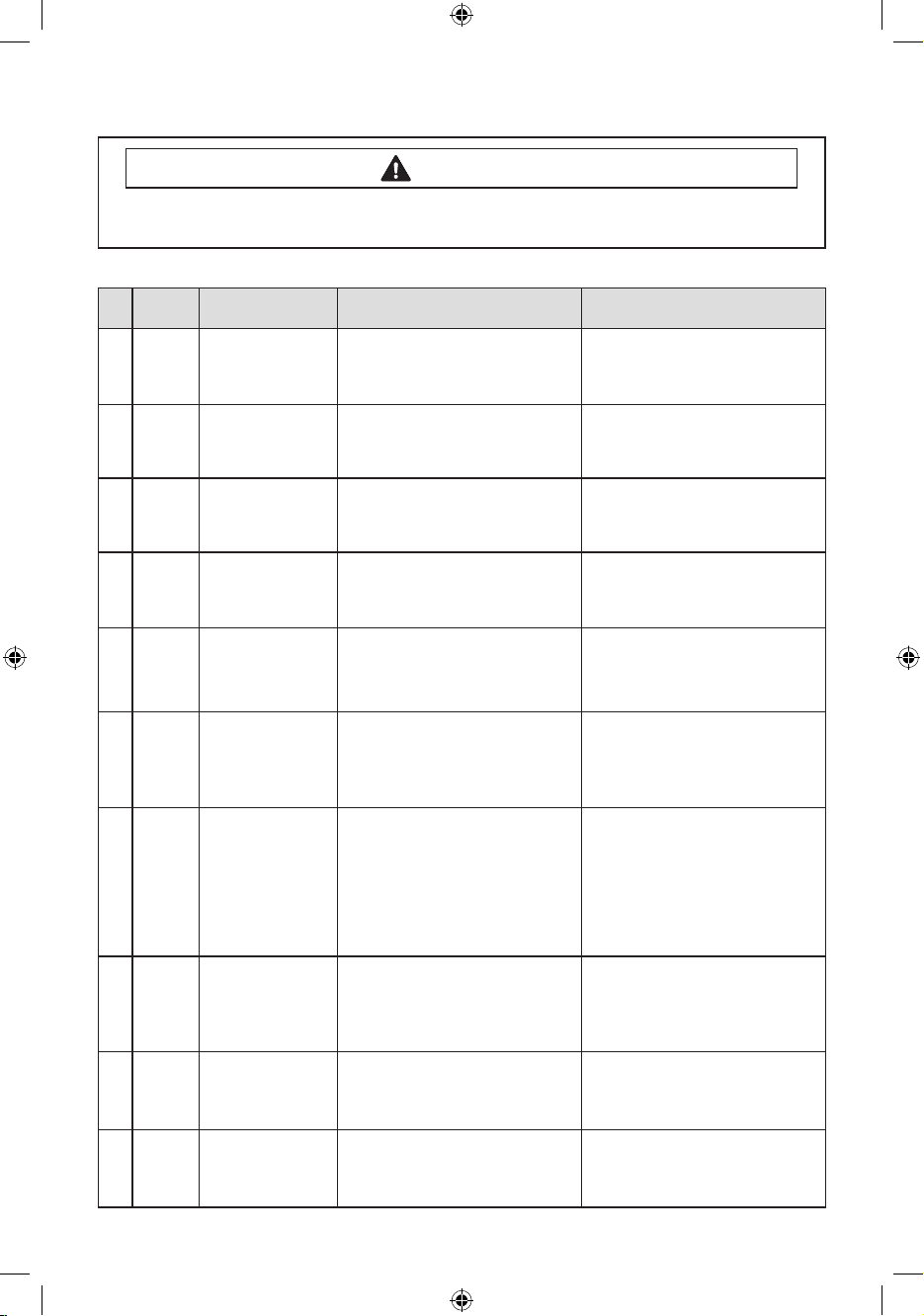
GENERAL ERROR FUNCTION
Error
NO
1 nd 1
Diagnostic Code
Code
Error Image
Description Corrective Action
The water level fails to drop below
the Reset Water Level within 15
minutes.
Go to “ Will Not Drain”
Troubleshooting Section.
2 LO 2
3 nF 3
4 FL 4
5 LE 8
6 LE 8
7 OE E
8 dc 10
9 E2 15
10 dL 18
Door fails to Unlock After 7
attempts.
When the lling Continues for
more than 40 minutes or there is no
change of water level for 6 minutes.
Door fails to lock after 7 attempts.
A water level lower than the Reset
water level (25.6Khz) is detected for
5 seconds during the Wash/Rinse
cycle.
Water Level Sensor Trouble. (When
the input signal from the water level
sensor is out of range, the unit will
send out beeping sounds and halts
the cycle.)
A fault is detected in the water level
sensor. Data (frequency) shows
the water level is at or above the
overow water level. (When this
condition is detected, the machine
will automatically starts draining
water until the water level falls
below the overow water level)
Unbalance or cabinet bump is
detected during nal spin, which
prevents the drum from spinning
over 150 rpm. (Never exceeds 150
RPM due to unbalanced load)
Jammed Key.(When key input
signals are coming out for more
than 30 seconds, it is regarded as
a jam.)
Door is detected as open when the
motor is operating.
Go to “ Will Not Unlock”
Troubleshooting Section.
Go to “ No Water Fill”
Troubleshooting Section.
Go to “ Will Not Lock”
Troubleshooting Section.
Go to “No Water Fill”
Troubleshooting Section.
Go to “No Water Fill”
Troubleshooting Section
First check to see that all of water
valves are not stuck. If water valves
are OK, check water level sensor.
Go to “Wet Clothes” Troubleshooting
Section.
Check all of keys. If A key is sensed
to be pressed, all keys will do not
respond.
Check for loose wire connections. Go
to “Quick Test Mode” and then do Door
lock/Unlock Test and Motor Test.
2
Techsheet-WF350AN-02834A-03_EN.indd 2 2011-09-28 �� 4:00:29
Page 3
ALIGNMENT AND ADJUSTMENTS
WARNING
To avoid risk of electrical shock, personal injury or death; disconnect power to washer
before servicing, unless testing requires power.
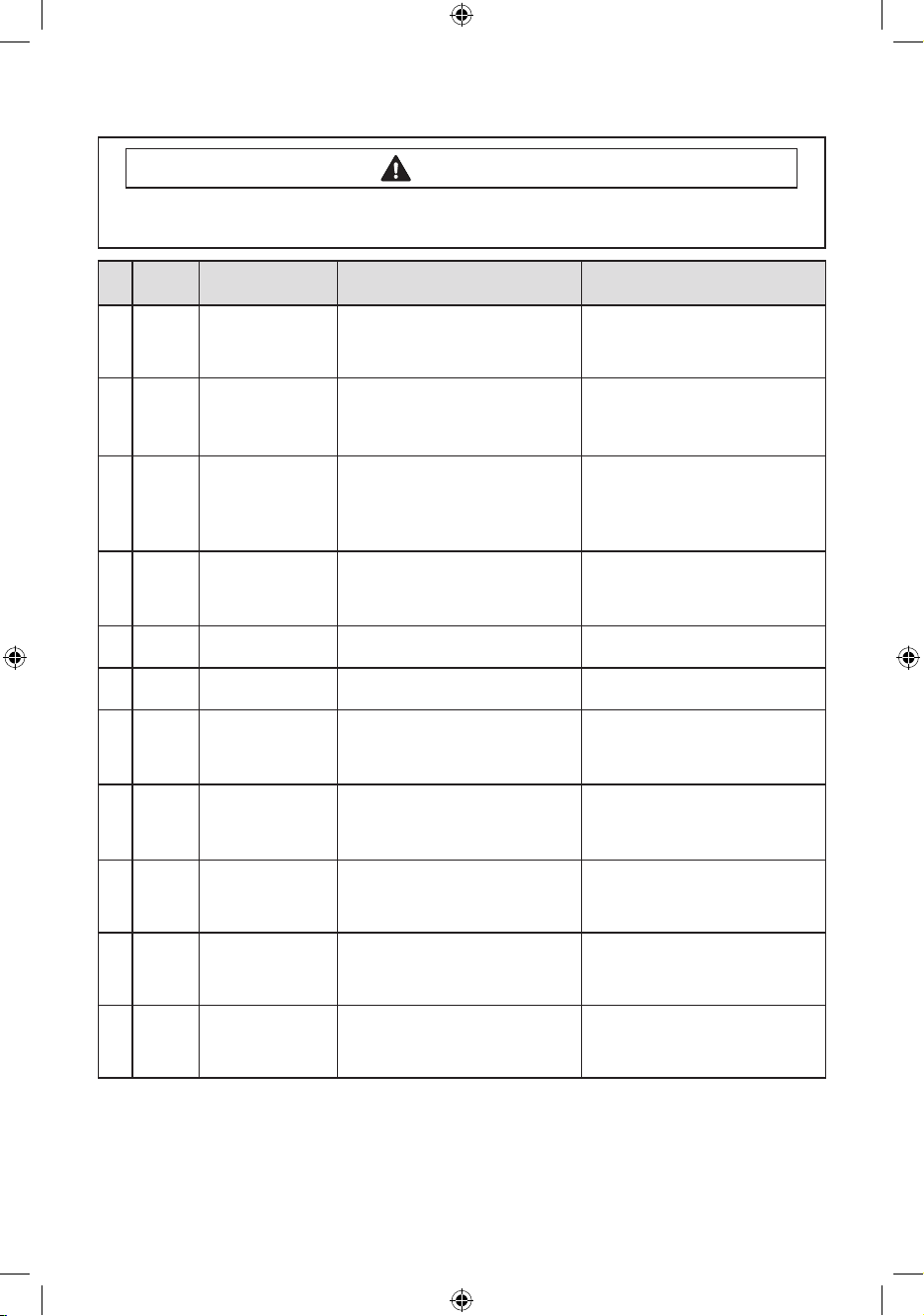
error
NO
Diagnostic Code
code
Error Image
Description Corrective Action
11 ds 22
12 tE 29
13
3E
14
Sr 34
15
Hr 36
16
nF1 5
2E
17 2E -
18 7E -
19 suds -
Door is detected as open while it is
trying to lock the door.
Abnormal high/low temperature or
resistance (Thermal sensor or PBA
resistance).
MICOM is attempting to drive the motor
but is not getting any response signals
from the hall sensor. Visual check shows
motor is not running. (Locked, Defective
Hall Sensor or Overload)
System Relay (Main Relay) Failure.
(PCB does not notice the relay
operation when there should be.)
Heater Relay Failure (No Heater
Relay Check Signal)
The hot/cold water hose connection
is not correct.
Voltage for motor control bus is
over or under specied limit.
Silver Care Kit (PCB) Failure.
Suds is detected during the washing
session. (“SUdS” is not an error. If the
washer is in suds period, “SUdS” will
light up instead of remaining time.)
Go to “Quick Test Mode” and then
do Door Lock/Unlock Test
Go to “ Board Input Test” and check
Water Temperature. Check loose
or pinched wires. Replace PCB or
thermistor.
Evaluate wire harness for loose or
unhooked connections. Go to “
Quick Test Mode” and test Motor.
Replace PCB.
Replace PCB
Please connect the hot/cold water
hose connection correctly.
Replace PCB
Check PCB ,Main PCB & Wireharness
Guide a user to reduce amount of
detergent usage.
20 AE
-
Communication error between SUB
PBA and MAIN PBA
Check Main PBA, SUB PBA & Wireharness. Replace PCB
SF1,
21
SF2,
-
System Error Replace PCB
SF3
3
Techsheet-WF350AN-02834A-03_EN.indd 3 2011-09-28 �� 4:00:29
Page 4
ALIGNMENT AND ADJUSTMENTS
WARNING
To avoid risk of electrical shock, personal injury or death; disconnect power to washer
before servicing, unless testing requires power.
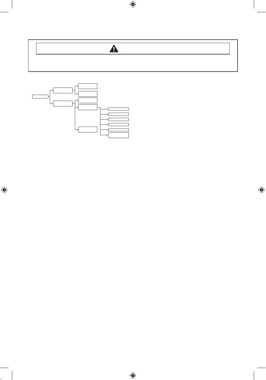
TEST MODE
Quick Test Mode
EEPROM Clear
Mode
Continuous Cycle
Mode
Service Mode
Demo Mode
Quick Spin Test Mode
Cycle Count Check Mode
S/W Version Check Mode
Fast Time Down Test Mode
Board Input Test Mode
Diagnostic Code
CheckMode
Special Test Mode
Power Off State
Power On State
(Normal User Mode)
Quick Test Mode
Denition of Quick Test Mode:
- Check operation of all LED’s (Verify faulty LED).
- Check model and software version.
- Check dierent operating modes (e.g. water valve, motor, door, drain pump, etc.).
How to Enter:
- Plug in the unit.
- Press Soil Level Key + Signal Key and Power Key at the same Time.
Important. Once test mode is performed, all data including the diagnostic code saved in the
EEPROM will be erased.
Test Mode:
Each Test Mode for the Squall is as follows in the
coming pages. The test modes indicated by the
red arrows are modes unable to get an access
once the washing cycle has started due to safety
resons.
4
Techsheet-WF350AN-02834A-03_EN.indd 4 2011-09-28 �� 4:00:29
Page 5
ALIGNMENT AND ADJUSTMENTS
WARNING
To avoid risk of electrical shock, personal injury or death; disconnect power to washer
before servicing, unless testing requires power.
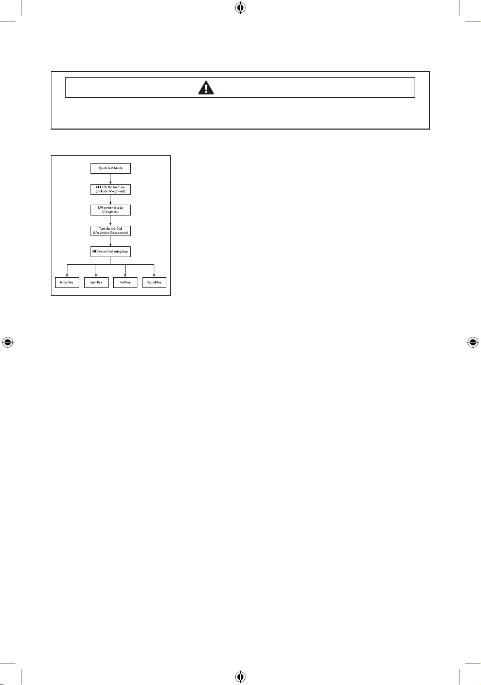
Quick Test Mode:
1. All LED’s light up and it sends out Beep Sound when it
enters into the Quick Test Mode. (Including 7-Segment)
2. Displays software version for a sec and Clear EEprom. (Ex. If
S/W Version is 49, 7-Segment will display E149)
3. When the version is displayed, turn the Jog-Dial so that
the version disappears. Press the following keys to test the
various components.
- Temp Key : Water Valve Test
- Spin Key : Door Lock/Unlock Test
- Soil Key : Water/Steam Heater Test(Steam Models)
Water Test(Non-Steam Models)
- Signal Key : Drain Pump Test
5
Techsheet-WF350AN-02834A-03_EN.indd 5 2011-09-28 �� 4:00:29
Page 6
ALIGNMENT AND ADJUSTMENTS
WARNING
To avoid risk of electrical shock, personal injury or death; disconnect power to washer
before servicing, unless testing requires power.
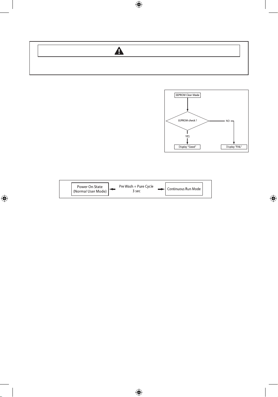
EEPROM Clear Check
Denition of EEPROM Clear Mode:
- EEPROM initialization.
- All course/option settings are to be reset to default values
after EEPROM initialization.
- When Service arises and it needs PCB replacement,
EEPROM should be reset.
How to Enter:
- The unit needs to be on.
-
Press Delay Start Key, Signal Key, and Power Key at the same time.
Continuous Run Mode
Denition of Continuous Run Mode:
- Will continuously repeat the current cycle until the Continuous Run Mode is cancelled.
How to Enter:
- Press Pre Wash Key and Pure Cycle Key together for 3 sec.
Continuous Run Mode:
1. Press
Pre Wash + Pure Cycle 3 sec
2.
Once in Continuous Run Mode, The seven segments will no longer display “0000” and will alternate
between displaying the number of cycles of the completed course and the remaining time of the course.
3. The Continuous Run Mode will repeat the previous cycle until continuous run mode is cancelled.
4.
During Continuous Run Mode, press Pre Wash + Pure Cycle 3 seconds to return to normal user
mode. The seven segments will no longer display the number of cycles and will display the
maintenance time only.
5. If you exit Service Mode after entering it from Continuous Mode, the washing machine returns
to Continuous Mode.
6. If power is lost in Continuous Run Mode (that is, when the power plug is disconnected or the
Power key is pressed turning the washing machine o), the mode is released when the washing
machine is turned on again.
during Power On State (Normal User Mode) .
6
Techsheet-WF350AN-02834A-03_EN.indd 6 2011-09-28 �� 4:00:30
Page 7
ALIGNMENT AND ADJUSTMENTS
WARNING
To avoid risk of electrical shock, personal injury or death; disconnect power to washer
before servicing, unless testing requires power.
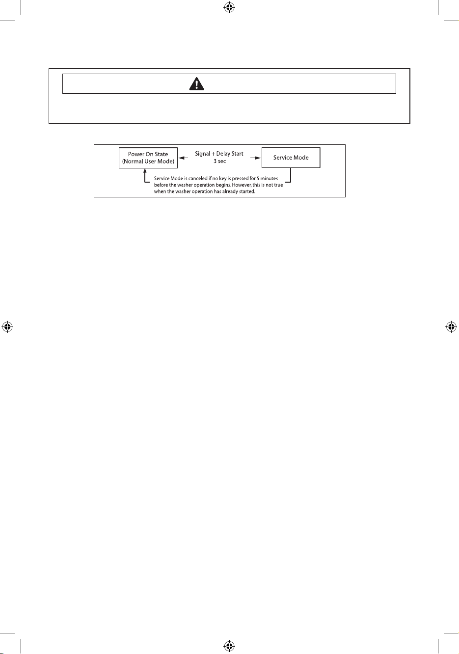
Service Mode
Denition of Service Mode:
- Service Mode enables service technicians to verify the operation of the washing machine and
do troubleshooting.
- Service Mode can be entered during all washing cycle without interrupting the cycle except
some of test modes.
- Various tests can be done with Service Mode. So, troubleshooting can be done based on the
resulting diagnostic codes.
How to Enter:
- To enter the Service Mode, press the Signal and Delay Start Keys for 3 seconds or until the unit
sends out beeping sounds.
Service Mode:
1. The washer must be on to go into the Service Mode.
2. The motor speed will be displayed when started (It displays 0 when the motor does not spin).
3. The present state of the machine will not be changed.
(i.e., the current cycle in progress will not be interrupted and only the display will change)
4. To exit Service Mode, press Signal and Delay Start Keys for 3 second again, or Power Key.If no key
is operated during Service Mode for 5 minutes, the machine will return to normal user mode.
7
Techsheet-WF350AN-02834A-03_EN.indd 7 2011-09-28 �� 4:00:30
Page 8

ALIGNMENT AND ADJUSTMENTS
WARNING
To avoid risk of electrical shock, personal injury or death; disconnect power to washer
before servicing, unless testing requires power.
Quick Spin Test Mode
Denition of Quick Spin Test Mode:
- Quick Spin Test Mode is to do Spin Check. (High RPM)
How to Enter:
- During Service Mode, press the Dealy Start and Pre Wash Keys for 3 seconds to enter Quick Spin
Test Mode. (Same for all Frontier 2 models.)
- Cannot enter once the washing cycle has started.
Quick Spin Test Mode:
As it enters into the Quick Spin Test Mode, it starts spinning and reaches to its maximum RPM.
Once the Spin speed reaches the maximum RPM, the speed drops immediately.
To hold Quick Spin Test Mode (entering Hold Speed Mode), press the Start/Pause button. If the
Start/Pause button is pressed during Quick Spin Test Mode, it will stop accelerating and hold its
spinning speed for 10 minutes before going back to Quick Spin Test Mode.
Also, to cancel the hold and allow Quick Spin Test Mode to continue, press the Dealy Start and Pre
Wash Keys together for 3 seconds.
If you hold down the Dealy Start and Pre Wash keys for three (3) seconds when the washing
machine is not in Hold Speed Mode, Quick Spin Mode is exited and Service Mode is restored.
8
Techsheet-WF350AN-02834A-03_EN.indd 8 2011-09-28 �� 4:00:30
Page 9
ALIGNMENT AND ADJUSTMENTS
WARNING
To avoid risk of electrical shock, personal injury or death; disconnect power to washer
before servicing, unless testing requires power.
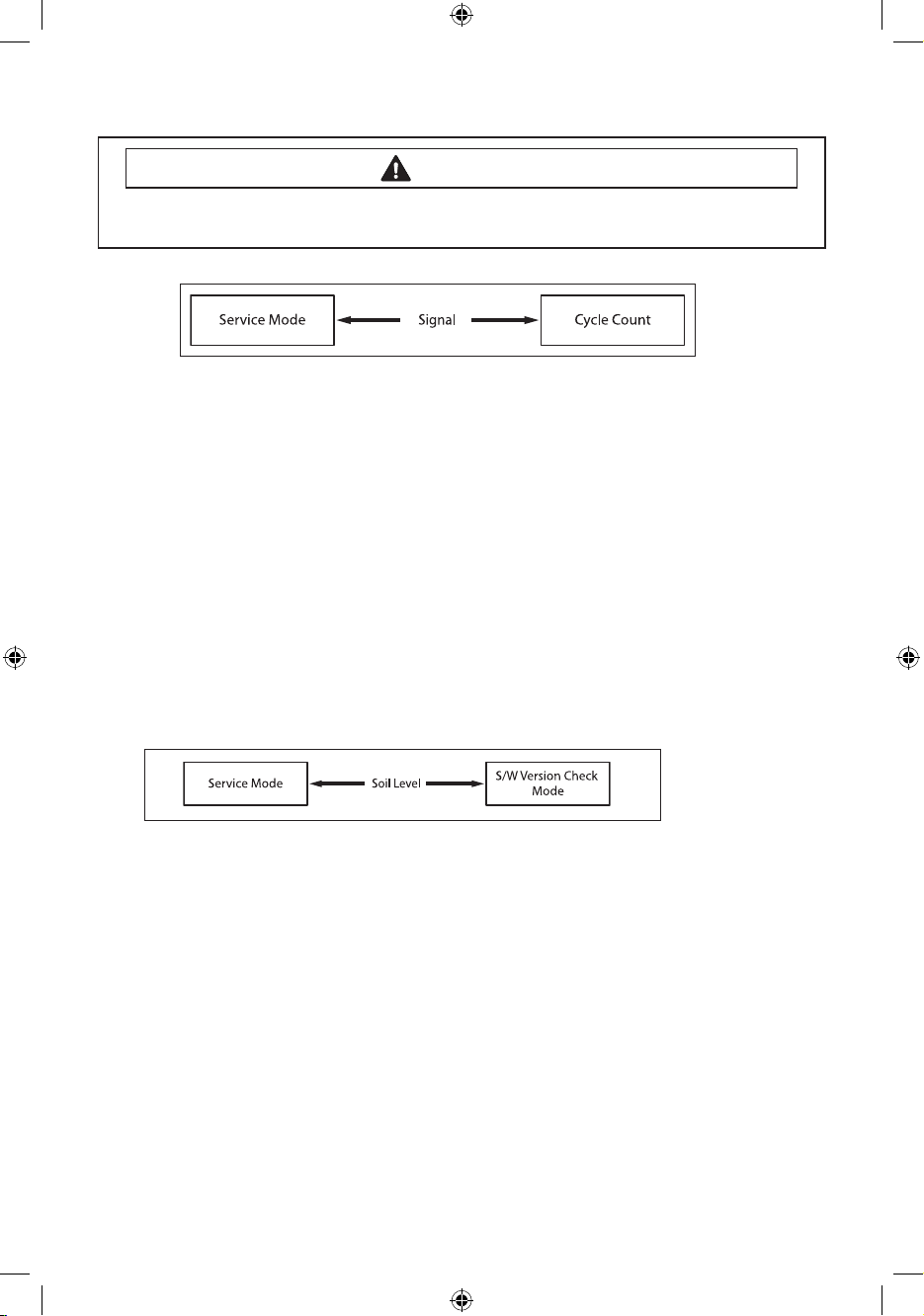
Cycle Count Check Mode
Denition of Cycle Count Check Mode:
- Cycle Count Check Mode is to tally up the number of washings.
How to Enter:
- To enter the Cycle Count Check Mode, press the Signal Key during Service Mode.
Cycle Count Check Mode:
1. Activate the Service Mode in advance.
2. When the Signal key is pressed, the total number of washings will light up and a signal LED will
glow.
3. The maximum number of cycles will be 9999.
The counter will roll over to 0 and start counting again after 9999.
4. The counting will be carried out at the end of the normal cycle.
(For normal and Continuous Run cycles, the count is carried out at the end of the cycles.
5. To exit the Cycle Count Check Mode, press the “Signal” key again.
S/W Version Check Mode
Denition of S/W Version Check Mode:
- S/W Version Check Mode is to bring up S/W Version information.
How to Enter:
- To enter the S/W Version Check Mode, press the Soil Level Key during Service Mode.
S/W Version Check Mode:
1. Activate the Service Mode in advance.
2. Press the Soil Level Key to bring up its software Version
EX) Generate AE49 at Version 49 (AE is Micom code, 49 is it’s software version)
3. To exit the S/W Version Check Mode, press the Soil Level S/W once again.
Then, it returns to the Service Mode with motor RPM illuminating.
9
Techsheet-WF350AN-02834A-03_EN.indd 9 2011-09-28 �� 4:00:31
Page 10
ALIGNMENT AND ADJUSTMENTS
WARNING
To avoid risk of electrical shock, personal injury or death; disconnect power to washer
before servicing, unless testing requires power.
Fast Time Down Test Mode
Denition of Fast Time Down Test Mode:
- Fast Time Down Test Mode is to forward the program to the next cycle stage.
How to Enter:
- To enter the Fast Time Down Test Mode, press the Temp key during Service Mode.
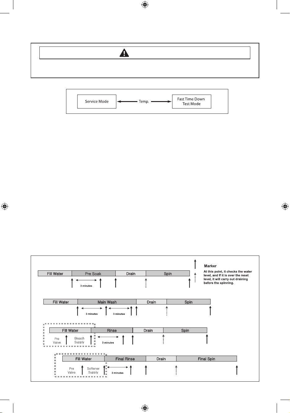
Fast Time Down Test Mode:
1. Activate the Service Mode in advance.
2. To forward the program to the next cycle stage, press the Temp key.
Each stage is located at key points of a complete cycle as follows:
- End of Each Fill (Beginning of Wash or Rinse Tumble Session)
Caution: Check if the current water level is higher than the Reset water level and then perform
the Fast time down test.
- Beginning of Drain Session
- Beginning of Spin Session (Here, it checks the water level. So, if it is over the reset level, it carries
out draining before the spinning.)
- Beginning of Fill Session
- Beginning of Bleach Fill
- Beginning of Fabric Softener Fill
- Every 3 minutes during Wash and Rinse Tumble Session
10
Techsheet-WF350AN-02834A-03_EN.indd 10 2011-09-28 �� 4:00:31
Page 11
ALIGNMENT AND ADJUSTMENTS
WARNING
To avoid risk of electrical shock, personal injury or death; disconnect power to washer
before servicing, unless testing requires power.
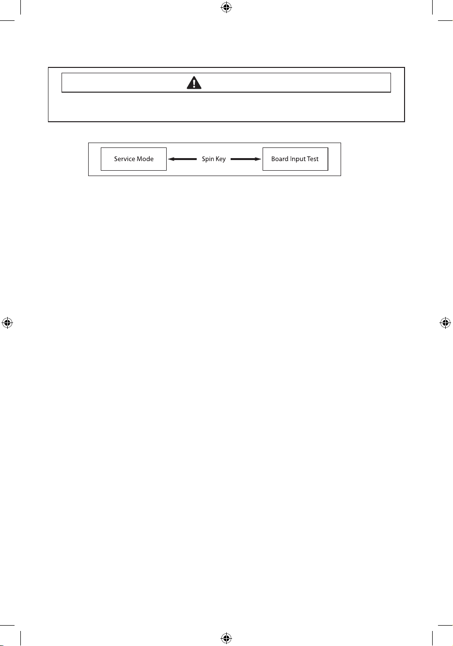
Board Input Test Mode
Denition of Board Input Test Mode:
- Board Input Test Mode is to displays a specied input after a key press.
How to Enter:
- To enter the Board Input Test Mode, press the Spin Key during Service Mode.
Board Input Test Mode:
1. Activate the Service Mode rst.
2. Press the Spin Key to start Board Input Test.
3. Turn the Jog-Dial so that the Pre Wash LED is turned on, and press the Start/Pause key. The Water
Temperature will be displayed in Celsius.
4. Turn the Jog-Dial so that the Extra Rinse(or Steam) LED is turned on, and press the Start/Pause
key. The Water Temperature will be displayed in Fahrenheit.
5. Turn the Jog-Dial so that the Cold/Cold LED is turned on, and press the Start/Pause key. The door
status will be displayed (OP if open, CL if closed).
6. Turn the Jog-Dial so that the No Spin LED is turned on, and press the Start/Pause key. The Door
Lock Switch status will be displayed (UL if unlocked, LO if locked).
7. Turn the Jog-Dial so that the Soil Level Light LED is turned on, and press the Start/Pause key. The
Water Frequency will be displayed.
8. Turn the Jog Dial so that the Signal O LED is turned on and press the Start/Pause button.
Within 3 seconds of pressing the button, the status of the Silver Nano kit is displayed.
1. Delayed: 0000
2. Normal: ---
3. Abnormal: ㅂE
11
Techsheet-WF350AN-02834A-03_EN.indd 11 2011-09-28 �� 4:00:31
Page 12
ALIGNMENT AND ADJUSTMENTS
WARNING
To avoid risk of electrical shock, personal injury or death; disconnect power to washer
before servicing, unless testing requires power.
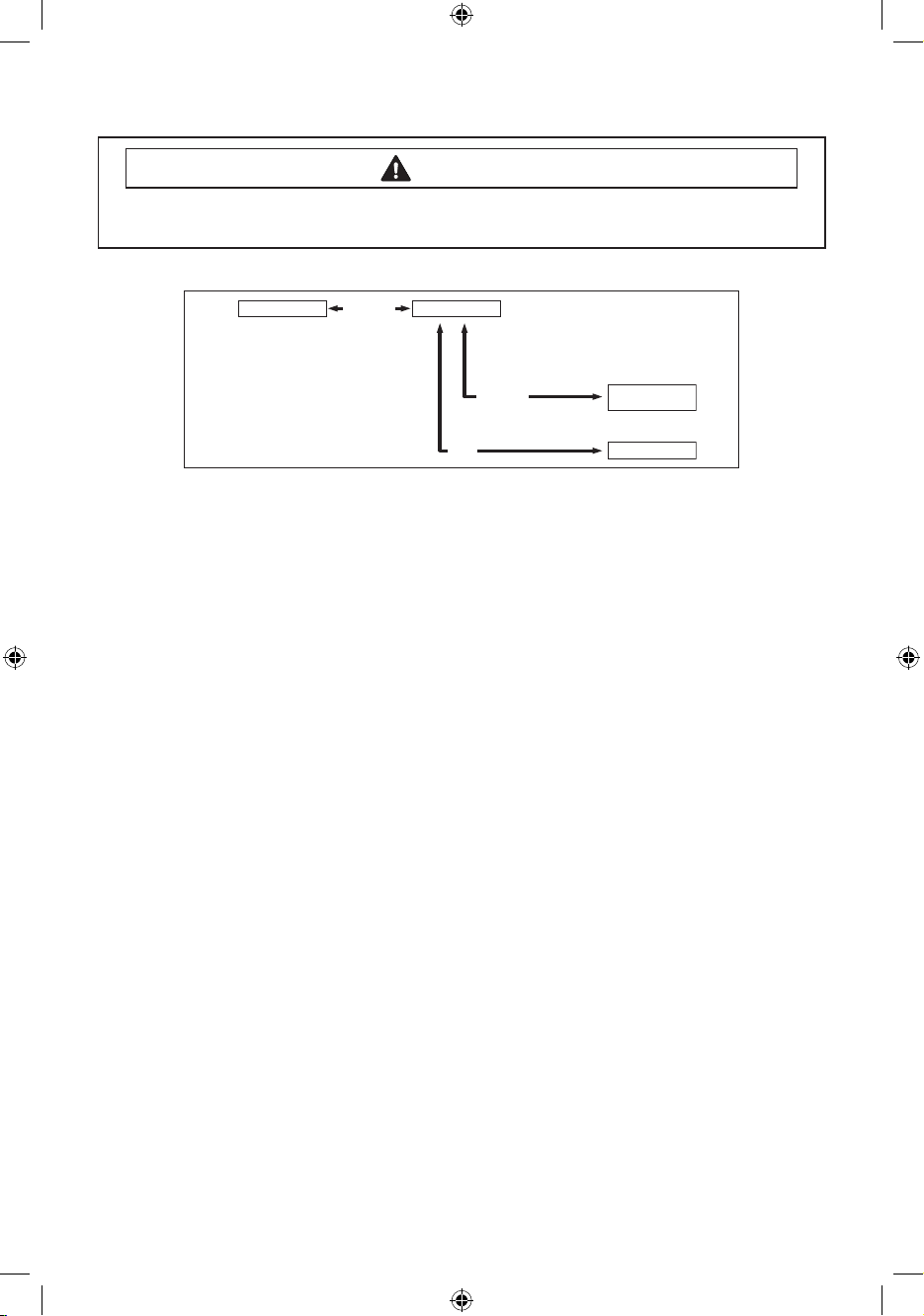
Diagnostic Code Check Mode
Service Mode
Pure Cycle
Diagnostic Code
Signal
Start/Pause
Pressing
Cycle No.
Before making Code
Cycle Count
Denition of Diagnostic Code Check Mode:
- Diagnostic Code Check Mode is to bring up the stored diagnostic codes (refere nce codes for
service technicians).
How to Enter:
- To enter the Diagnostic Code Check Mode with code “d” ashing, press the Pure Cycle key during
Service Mode.
Board Input Test Mode:
1. Activate the Service Mode rst.
2. Press the “Pure Cycle key” key to start Diagnostic Code Check Mode with Code “d” ashing.
3. To cycle through the diagnostic codes (d1,d2,d3~d9), turn the Rotary Cycle Selector in one
direction (either Clockwise or Counterclockwise).
4. Now, when turning the Rotary Selector Key in the same direction, it shows diagnostic codes
from the latest (d1).
5. When turning it in the opposite direction, it shows the diagnostic codes in the reverse order.
Ex) When it stops at d5 and turns backward, it shows from d4 down to “d”. Refer to Diagnostic
Code.
12
Techsheet-WF350AN-02834A-03_EN.indd 12 2011-09-28 �� 4:00:31
Page 13
ALIGNMENT AND ADJUSTMENTS
WARNING
To avoid risk of electrical shock, personal injury or death; disconnect power to washer
before servicing, unless testing requires power.
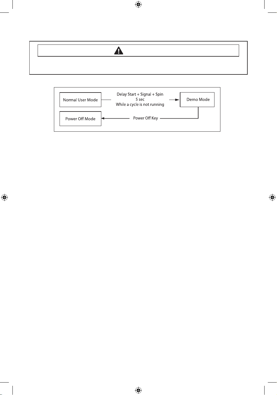
Demo Mode
- Demo mode is entered when the Delay Start + Signal + Spin buttons are held down for ve (5)
seconds simultaneously in the power on state.
- When entering Demo mode, the buzzer rings three (3) times and “- - - -” is displayed on the 7
segment display and all other LEDs are turned o. (Initial Demo mode)
- Demo mode consists of WASH, SPIN and LED modes.
- If the Temp button is pressed during the initial Demo mode, “WASH” blinks on the 7 segment
display and the washing machine enters WASH mode.
- If the Start/Pause button is pressed in WASH mode, the door is locked (Door Lock) and the motor
rotates left and right at 45 RPM in a 7 sec on and 3-sec o cycle.
- WASH mode continues up to ve (5) minutes once started. After the ve (5) minutes have
elapsed, “- - - -” is displayed on the 7 segment display and the initial Demo mode is maintained.
- If the Start/Pause button is pressed during a WASH mode operation, “- - - -” is displayed on the 7
segment display and the initial Demo mode is maintained.
- If the Spin button is pressed in the initial Demo mode, “Spin” blinks on the 7 segment display
and the washing machine enters SPIN mode.
- If the Start/Pause button is pressed in the SPIN mode, the door is locked (Door Lock) and a spin
is operated at 1150 RPM. When the speed reaches 0 RPM, the No Spin, Low, Medium, High, and
Extra High LEDs are turned on.
- During a spin operation, the No Spin LED turns on when the speed is lower than 400 RPM. The
Low LED turns on between 400 RPM and 800 RPM. The Medium LED turns on between 800 RPM
and 1000 RPM. The High LED turns on at higher than 1000 RPM.
- SPIN mode continues up to four (4) minutes once started. After the four (4) minutes have
elapsed, “- - - -” is displayed on the 7 segment display and the initial Demo mode is maintained.
- If the Start/Pause button is pressed during a SPIN mode operation, “- - - -” is displayed on the 7
segment display and the initial Demo mode is maintained.
- If the Pure Cycle button is pressed during the initial Demo mode, “LED” is displayed on the 7
segment display and the washing machine enters LED mode.
- If the Start/Pause button is pressed in LED mode, all LEDs are turned on. The LED mode
continues up to thirty (30) seconds once started. After the thirty (30) seconds have elapsed, “- - -
-” is displayed on the 7 segment display and the initial Demo mode is entered.
- If the Start/Pause button is pressed during an LED mode operation, “- - - -” is displayed on the 7
segment display and the initial Demo mode is entered.
13
Techsheet-WF350AN-02834A-03_EN.indd 13 2011-09-28 �� 4:00:32
Page 14
TROUBLE SHOOTING
WARNING
To avoid risk of electrical shock, personal injury or death; disconnect power to washer
before servicing, unless testing requires power.
TROUBLE DIAGNOSIS
- As the micom wash machine is congured of the complicate structure, there might be the
service call.
Below information is prepared for exact trouble diagnosis and suitable repair guide.
Caution for the Repair and Replacement
Please follow below instruction for the trouble diagnosis and parts replacement.
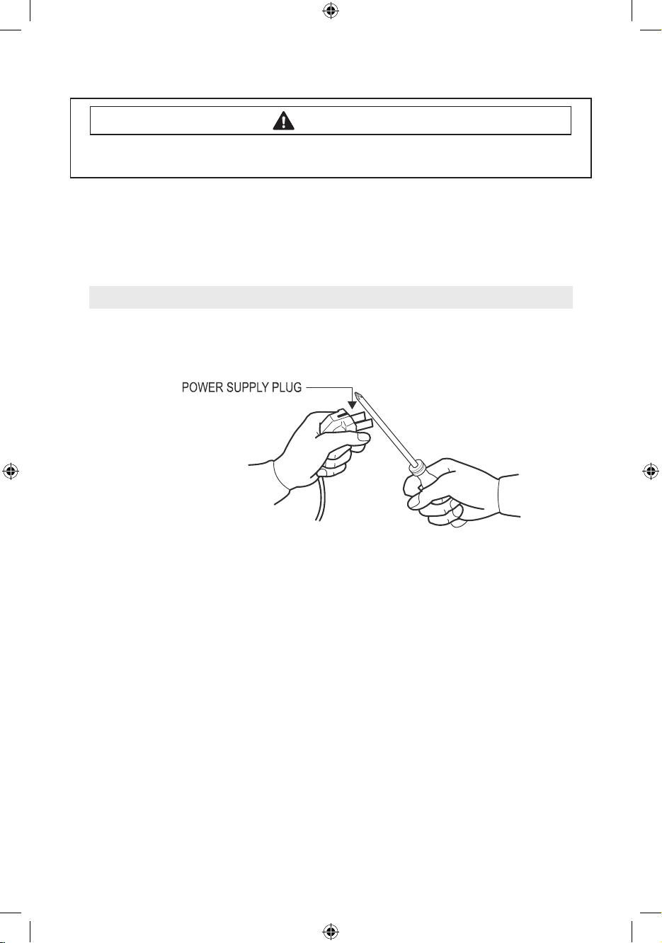
1) As some electronic components are damaged by the charged static electricity from the resin
part of machine or the human body, prepare the human body earth or remove the potential
dierence of the human body and machine by contacting the power supply plug when the
work contacting to PCB is executed.
2) Since AC120V is applied to the triac T1 and T2 on P.C.B, the electric shock may occur by touching
and be careful that the strong and weak electricity are mixed.
3) As the P.C.B assembly is designed for no trouble, do not replace the P.C.B assembly by the wrong
diagnosis and follow the procedure of the trouble diagnosis when the micom is not operated
normally.
14
Techsheet-WF350AN-02834A-03_EN.indd 14 2011-09-28 �� 4:00:32
Page 15
TROUBLE SHOOTING
WARNING
To avoid risk of electrical shock, personal injury or death; disconnect power to washer
before servicing, unless testing requires power.
TROUBLE DIAGNOSIS
Will Not Start
• Plug the unit into the wall outlet. Check for proper voltage.
• Check fuse or reset circuit breaker.
• Push any key to turn on the washer and press the Start/Pause key to run the washer.
• Close door and push the Start/Pause key to run the washer.
• Check if washer is in a pause, soak or suds process. Wait briey and it may start. (If the washer is in suds
period, Suds will light up instead of remaining time.)
• Check for restricted drain system. (If there is electrical problem in drain system, “nd” error will occur after 15
minutes.)
• Check Water Supply.
• Check the line or water valve screen lter.
• Check if PCB connectors are assembled properly.
• Check if CN2 terminals on PCB are in good condition. (Refer to PCB Connector Check.)
• Replace PCB.
Leaking
• Make sure inlet hose connections are not leaking. Check for rubber gasket damage due to over tightening.
• Check standpipe for leak. Wrap a dry rag around the standpipe opening.
If rag becomes wet, leak is fault of home plumbing.
Be sure the standpipe is capable of accepting the ow of water from the washer.
• Make sure end of drain hose is correctly inserted and secured to drain standpipe.
• Check internal hose connections (ll, drain systems, dispenser hoses & clamps).
• Check rubber boot. Remove, reposition and reinstall, if necessary.
• Check for possible kinked dispenser to outer tub hose. Hot water pressurization may force door open.
No Tumble
• Start normal cycle with an empty machine and allow a ll to check tumble.
• Perform Quick Spin Test. (Before test, make sure that the tumbler is empty.)
• Check for loose connections at Machine Control Board, Pressure Switch, Motor, Tach Harness and Motor
Control. (Refer to the component testing procedure)
• Check motor windings resistance.
CN5 pins 1 & 3 = 11.6ohms ±7%,
Pins 1 & 2 = 11.6ohms ±7%,
Pins 2 & 3 = 11.6 ohms ±7%
• Faulty Main Control Board.
• Faulty motor.
Will Not Spin
• Make sure to close the door completely.
• Check for water left inside the washer. If so, go to “Will Not Drain”.
• Perform Quick Test Mode or Quick Spin Test. Does the washer spin? (Before the test, empty the unit inside.)
If it doesn’t tumble after the above, change PCB. When the problem persists, change the motor.
• Perform Quick Test Mode or Quick Spin Test. Does the washer spin? If it does, Check Possible unbalanced
load scenario in normal mode.
• Check for loose connections at PCB, Water Level Sensor, Motor, Hall Sensor Wire Harness. (CN7,CN5,CN6)
(Refer to the Component Testing Procedure.)
• Check motor windings resistance. (CN5 Pin1&3 = 11.6 ohms (at ±7% 20°C/68°F),
Pin1&2 = 11.6ohms (at ±7% 20°C),
Pin2&3 = 11.6 ohms (at ±7% 20°C))
15
Techsheet-WF350AN-02834A-03_EN.indd 15 2011-09-28 �� 4:00:32
Page 16

TROUBLE SHOOTING
WARNING
To avoid risk of electrical shock, personal injury or death; disconnect power to washer
before servicing, unless testing requires power.
TROUBLE DIAGNOSIS
No Water Fill
• Perform Quick Test Mode. Check all of Water Valves visually.
(Pre Wash Valve, Cold Water Valve, Bleach Water Valve, Softener dispenses using Cold & Bleach Water Valve,
and Hot Water Valve.)
• Check if water taps are turned on fully.
• Check Water Valves and Water Level Sensor (Refer to PCB Connector Check)
• Check if there is any kink in inlet hoses.
• Check if inlet screens are clogged up.
• Check if water has enough pressure. If so, nd out its contributors.
• Check if there is any frozen area in the unit (Drain Hose, etc)
• Measure the resistance of Water Valve Coil.
(It should read 1.18K ohms. Check Pin#1 of CN2 and PIN#1,2,7,8,9 of CN3)
• Check Pressure S/W and PCB for loose connections. (Refer to PCB Connector Check.)
Tub Full of Suds
• Go to “Will Not Drain” and “Will Not Spin” and check the draining.
• Check PCB and Drain Pump for any loose wire connection.
• Perform Quick Test Mode or Board Output Test to drain.
• Use HE (High-Eciency) or low sudsing detergent specially formulated for front load washers.
• Reduce the amount of detergent for that specic load size and soil level. Keep in mind that towel creates
more suds generally.
• Reduce the amount of detergent when water is soft, or laundry is small or lightly soiled.
• Do one more washing cycle with cold water and a table spoon of salt without detergent.
16
Techsheet-WF350AN-02834A-03_EN.indd 16 2011-09-28 �� 4:00:32
Page 17

TROUBLE SHOOTING
WARNING
To avoid risk of electrical shock, personal injury or death; disconnect power to washer
before servicing, unless testing requires power.
TROUBLE DIAGNOSIS
Wet Clothes
• Unbalance due to not enough load. Put additional load.
•
Due to excessive suds by using general detergent. Use HE (High-Eciency) or reduce its quantity.
• Low Spin Speed or Drain Only was selected.
• Go to “ Will Not Spin”.
Will Not Lock
• Door is not aligned or closed properly.
• Perform Quick Test Mode. Check Door Lock.
Check the output voltage of Door Lock Coil.
If it reads 120V, change Door Lock Switch, and if not, change PCB. (Refer to PCB Connector Check.)
• Read Lock Switch and PCB (CN3). (Refer to PCB Connector Check.)
• Try Door Lock and check for 120V to Door Lock Connector. If 120V present, change Main Control Board and
if not, change Door Lock switch.
Will Not Unlock
• Check if the door is being pushed out, which may keep it from unlocking.
• Door locks itself when the water level is too high. Opening door will result in water draining from door
opening.
• Check the following with Board Input Test Mode.
Water Level (frequency): Over 23.80 KHz.
If so, refer to “Will Not Drain”.
Temperature (Inside Drum): Higher than 60ºC/140ºF.
If so, wait until it drops.
When everything is normal, check PCB connectors and Door Lock Switch.
• Drain manually after removing the plastic drain hose holder.
• Display shows “LO”. Turn o and on the unit. If “LO” keeps illuminating, check PCB and Door Lock Switch.
17
Techsheet-WF350AN-02834A-03_EN.indd 17 2011-09-28 �� 4:00:32
Page 18

TROUBLE SHOOTING
WARNING
To avoid risk of electrical shock, personal injury or death; disconnect power to washer
before servicing, unless testing requires power.
TROUBLE DIAGNOSIS
• Read Lock Switch and PCB (CN2 & CN3). (Refer to PCB Connector Check.)
• Perform Quick Test Mode. Check Door Lock. Check the output voltage of Door Lock Coil.
If it reads 120V, change Door Lock Switch, and if not, change PCB. (Refer to PCB Connector Check.)
No Key Operation
• Option and Function buttons respond dierently according to each cycle.
• Child Lock is being activated. To exit, hold down Soil Level Key and Signal Key simultaneously until it sends
out a beeping sound.
• When “End“ illuminates on the display, only Power button works. Press Power button and make new cycle
selections.
Will Not Drain
• Check for any kink on the drain hose. If any, straight it out.
• Check for any restriction in the drain hose.
• Close the door and press the Start/Pause Button. For safety reasons, the washer does not tumble or spin with
the door open.
• When it is freezing outside, check if it is frozen inside the drain hose.
• Check if the water level signal input is correct. Go to Board Input Test Mode.
• Go to Quick Test Mode and do Drain Pump Test.
• Check if there is any twist in the hose (the one between Tub and Drain Pump).
• Check if it reads AC 120V at the pump when a spin cycle is selected.
• Read the winding resistance of the pump motor. (14.2±7% Ohms)
• Check the pump at CN3(PIN3) on PCB. It should read AC 110~120V. (Refer to PCB Connector Check)
18
Techsheet-WF350AN-02834A-03_EN.indd 18 2011-09-28 �� 4:00:32
Page 19

TROUBLE SHOOTING
WARNING
To avoid risk of electrical shock, personal injury or death; disconnect power to washer
before servicing, unless testing requires power.
TROUBLE DIAGNOSIS
Wrong Water Temperature
• Check if both of the water taps are fully open.
• Make sure the domestic water heater is set to deliver water lower than 120°F (49°C) hot water at the tap.
Also check water heater capacity and recovery rate.
• If the water heater is located far from the washer, screw out the hot water tap and let its water pass until you
get hot water.
• Too Hot/Too Cold: Reduced amount of water is supplied while PCB controls the inux to regulate the actual
temperature of the water in the tub. This may appear to be signicantly hotter/colder than expected.
• Check if the temperature selection is correct.
• Disconnect inlet hoses from the Water Valve and remove any residue in the inlet screens.
Noisy and/or Vibration/Walking
• Check if the washer is leveled and the lock nuts are tightened up on the bottom plate.
• Check if all of the shipping bolts and spacers are removed from the back panel.
•
Check if load is big enough and there is no unbalance.If there is not enough load, put in a few towels to balance it.
• Check if the motor is fastened enough.
• Remove various trouble contributors (such as dust coat on the oor).
Rubber Feet Leaving Marks on Floor
• Use a pencil eraser to remove mark.
• Walk washer into location, do not drag.
Additive Cups Full of Water
• Small amount of water in bottom of additive cups is normal.
• Remove and wash Dispenser Tray, removable Cup, and Rinse Cap.
• Level washer.
Buttons do not Respond
• Option and Function buttons respond dierently according to each cycle.
• Child Lock feature has been selected. To disable feature press and hold Temp and Spin simultaneously until a
beep is heard.
• When display shows “End”, only the Power button will function. Press Power and make new cycle selections.
19
Techsheet-WF350AN-02834A-03_EN.indd 19 2011-09-28 �� 4:00:32
Page 20

TROUBLE SHOOTING
WARNING
To avoid risk of electrical shock, personal injury or death; disconnect power to washer
before servicing, unless testing requires power.
PROBLEM CHECKING AND METHOD OF PCB
- If you plug in the power cord and turn Power S/W on, memorized data is displayed.
If any data is not displayed, check the followings.
Thermistor Check
Check Voltage at Pin #4 and #5 of CN7
Tester Check = DC 2.5V
If it reads 5V, Check if its connector is engaged
properly
Door Switch Check
Check Voltage at Pin #1 and #3 of CN4
When Door Open = DC 25V
When Door Close = DC 0V
Water Sensor Check
Check Voltage and Frequency at Pin #5 and #6
of CN7
Reset water level = DC2.5V, 25.8KHz
Check Voltage and Frequency at Pin #5 and #7
of CN7
Reset water level = DC2.5V, 25.8KHz
Hall Sensor Check
Check Voltage at Pin #4 and #2 of CN6
Tester Check = DC 0V or 3.75V
Check Voltage at Pin #4 and #3 of CN6
Tester Check = DC 0V or 3.75V
Motor Check
Resistance at Pin #1 and #2 of CN5 = 12Ω
Resistance at Pin #1 and #3 of CN5 = 12Ω
Resistance at Pin #2 and #3 of CN5 = 12Ω
Door Lock Check
Check Voltage at Pin #3 of CN2 and Pin #1 of CN3
When Door Lock = AC 120V
Door Unlock Check
Check Voltage at Pin #3 of CN2 and Pin #2 of
CN3
When Door Unlock = AC 120V
Drain Motor Check
Check Voltage at Pin #3 of CN2 and Pin #3 of
CN3
When Drain Motor operates = AC 120V
Water Valve Check
Check Voltage at Pin #3 of CN2 and Pin
#1,2,7,8,9 of CN3
When each valve operates = AC 120V
AC Power Check
Check Voltage at Pin #1 and #2 of CN2
Tester Check = AC 120V
Wash Heater Relay Check
Check Voltage at Pin #3 of CN2 and PIN #2 of
RY3
When Heater Relay operates = AC 120V
Steam Heater Relay Check(Only Steam Models)
Check Voltage at Pin #3 of CN2 and PIN #2 of
RY4
When Heater Relay operates = AC 120V
20
Techsheet-WF350AN-02834A-03_EN.indd 20 2011-09-28 �� 4:00:33
Page 21

WIRING DIAGRAM
WARNING
To avoid risk of electrical shock, personal injury or death; disconnect power to washer
before servicing, unless testing requires power.
21
Techsheet-WF350AN-02834A-03_EN.indd 21 2011-09-28 �� 4:00:33
Page 22

WATER FLOW DIAGRAM
WARNING
To avoid risk of electrical shock, personal injury or death; disconnect power to washer
before servicing, unless testing requires power.
22
Techsheet-WF350AN-02834A-03_EN.indd 22 2011-09-28 �� 4:00:33
Page 23

MEMO
Techsheet-WF350AN-02834A-03_EN.indd 23 2011-09-28 �� 4:00:33
Page 24

Techsheet-WF350AN-02834A-03_EN.indd 24 2011-09-28 �� 4:00:33
Page 25

LAVE-LINGE
Informations techniques
• En raison des risques de blessure ou de dommages matériels existants, demandez toujours à un
technicien qualié d'eectuer les opérations d'entretien ou de réparation de l'appareil.
• Reportez-vous au manuel de réparation pour connaître les consignes d'installation, d'utilisation,
de test, de dépannage et de démontage détaillées.
ATTENTION
Toutes les consignes de sécurité gurant dans le manuel de réparation doivent être respectées.
AVERTISSEMENT
An d'éviter tout risque d'électrocution légère ou mortelle, débranchez le lave-linge avant
de procéder aux réparations (sauf si le test nécessite sa mise sous tension).
Code n°: DC68-02834A-03_CFR
1
Techsheet-WF350AN-02834A-03_CFR.indd 1 2011-09-28 �� 3:52:25
Page 26

ALIGNEMENTS ET RÉGLAGES
AVERTISSEMENT
An d'éviter tout risque d'électrocution légère ou mortelle, débranchez le lave-linge avant
de procéder aux réparations (sauf si le test nécessite sa mise sous tension).
PROBLÈMES PRINCIPAUX
Code
N°
d'erreur
1 nd 1
2 LO 2
3 nF 3
4 FL 4
5 LE 8
6 LE 8
7 OE E
8 dc 10
9 E2 15
10 dL 18
Achage
du code de
diagnostic
Description Action corrective
Le niveau d'eau ne descend pas sous le
niveau d'eau de réinitialisation dans les
15minutes.
Le hublot ne se déverrouille pas après
sept tentatives.
Le remplissage se poursuit pendant
plus de 40minutes ou le niveau d'eau
ne change pas pendant 6minutes.
Le hublot ne se verrouille pas après
sept tentatives.
Un niveau d'eau inférieur au niveau
d'eau de réinitialisation (25,6Khz) est
détecté durant 5secondes pendant le
cycle de lavage/rinçage.
Problème au niveau du capteur
de niveau d'eau. (Lorsque le signal
d'entrée émis par le capteur de niveau
d'eau se situe en dehors de la plage,
l'appareil émet des signaux sonores et
le programme s'interrompt.)
Une erreur a été détectée sur
le capteur de niveau d'eau. Les
données (fréquence) indiquent que
le niveau d'eau atteint ou dépasse
le niveau de trop-plein. (Lorsque cet
état est détecté, la machine lance
automatiquement un cycle de vidange
jusqu'à ce que le niveau d'eau passe
sous le niveau de trop-plein.)
Un déséquilibre ou un choc au niveau
du châssis est détecté pendant
l'essorage nal, ce qui empêche
le tambour de tourner à plus de
150tr/min. (Jamais d'essorage à
plus de 150tr/min en cas de charge
déséquilibrée)
Bouton bloqué. (L'activation des
signaux d'entrée de bouton pendant
plus de 30secondes est considéré
comme un blocage.)
Le hublot est détecté comme étant
ouvert alors que le moteur tourne.
Consultez la section Dépannage «Pas
de vidange».
Consultez la section Dépannage «Le
hublot ne se déverrouille pas».
Consultez la section Dépannage «Pas
de remplissage».
Consultez la section Dépannage «Le
hublot de se déverrouille pas».
Consultez la section Dépannage «Pas
de remplissage».
Consultez la section Dépannage
«Pas de remplissage».
Vériez tout d'abord que les vannes ne
sont pas grippées. Si elles ne le sont
pas, vériez le capteur de niveau d'eau.
Consultez la section Dépannage
«L'essorage n'a pas fonctionné».
Vériez tous les boutons. Si UN SEUL
bouton est considéré par l'appareil
comme étant enclenché, aucun autre
bouton ne répond.
Vériez que les câbles sont bien
connectés. Consultez la section «Mode
de test rapide», puis eectuez un test
de verrouillage/déverrouillage du
hublot et un test du moteur.
2
Techsheet-WF350AN-02834A-03_CFR.indd 2 2011-09-28 �� 3:52:25
Page 27

ALIGNEMENTS ET RÉGLAGES
AVERTISSEMENT
An d'éviter tout risque d'électrocution légère ou mortelle, débranchez le lave-linge avant
de procéder aux réparations (sauf si le test nécessite sa mise sous tension).
code
N°
d'erreur
11 ds 22
12 tE 29
13
14
15
16
17 2E -
3E 2E
Sr 34
Hr 36
nF1 5
Achage
du code de
diagnostic
Description Action corrective
Le hublot est détecté comme étant
ouvert alors que le système tente de le
verrouiller.
Température ou valeur de la résistance
anormalement haute/basse (capteur
thermique ou carte de circuit imprimé).
Le MICOM essaie d'entraîner le moteur
mais n'obtient aucun signal de réponse
de la part du capteur à eet Hall. Un
contrôle visuel conrme que le moteur
ne fonctionne pas. (Verrouillage,
Capteur à eet Hall défectueux ou
Surcharge)
Échec du relais du système (relais
principal). (La carte de circuit imprimé
ne détecte pas le fonctionnement en
relais quand il le faudrait.)
Échec du relais de la résistance (pas
de signal de contrôle du relais de la
résistance)
Le tuyau d'eau chaude/d'eau froide n'a
pas été raccordé correctement.
La tension du jeu de barres de la
commande du moteur est supérieure
ou inférieure à la limite spéciée.
Consultez la section «Mode de test
rapide», puis eectuez un test de
verrouillage/déverrouillage du hublot.
Consultez la section «Test des entrées
au niveau de la carte» et vériez la
température de l'eau. Vériez que les
câbles sont bien connectés et qu'ils ne
sont pas pincés. Remplacez la carte de
circuit imprimé ou la thermistance.
Vériez que le faisceau électrique n'est
pas desserré ou débranché. Consultez
la section «Mode de test rapide» et
eectuez un test du moteur.
Remplacez la carte de circuit imprimé.
Remplacez la carte de circuit imprimé.
Veuillez procéder au raccordement
correct du tuyau.
Remplacez la carte de circuit imprimé.
18 7E -
19 suds -
20 AE
SF1, SF2,
21
SF3
Échec du kit Silver Care (carte de circuit
imprimé).
La présence de mousse est détectée
pendant le cycle de lavage. («SUdS»
n'est pas une erreur. Si le lave-linge se
trouve dans une phase de lessivage, le
message «SUdS» s'ache au lieu du
temps restant.)
-
-
Erreur de communication entre la carte
de circuit imprimé secondaire et la
carte de circuit imprimé principale
Erreur système Remplacez la carte de circuit imprimé.
Vériez la carte de circuit imprimé, la
carte de circuit imprimé principale et le
faisceau électrique.
Conseillez à l'utilisateur de réduire la
quantité de lessive.
Vériez la carte de circuit imprimé
principale, la carte de circuit imprimé
secondaire et le faisceau électrique.
Remplacez la carte de circuit imprimé
3
Techsheet-WF350AN-02834A-03_CFR.indd 3 2011-09-28 �� 3:52:25
Page 28

ALIGNEMENTS ET RÉGLAGES
AVERTISSEMENT
An d'éviter tout risque d'électrocution légère ou mortelle, débranchez le lave-linge avant
de procéder aux réparations (sauf si le test nécessite sa mise sous tension).
MODE DE TEST
Quick Test Mode
EEPROM Clear
Mode
Continuous Cycle
Mode
Service Mode
Demo Mode
Quick Spin Test Mode
Cycle Count Check Mode
S/W Version Check Mode
Fast Time Down Test Mode
Board Input Test Mode
Diagnostic Code
CheckMode
Special Test Mode
Power Off State
Power On State
(Normal User Mode)
Mode de test rapide
Dénition du mode de test rapide:
- Vérier le bon fonctionnement de toutes les DEL (Contrôler les DEL défectueuses).
- Vérier le modèle et la version du logiciel.
- Vérier les diérents modes de fonctionnement (ex.: vanne d'eau, moteur, hublot, pompe de
vidange, etc.).
Pour sélectionner ce mode:
- Branchez l'appareil.
- Appuyez simultanément sur les boutons Degré de salissure, Signal et Mise en marche.
Important: Une fois le mode de test réalisé, toutes les données, y compris le code de diagnostic,
enregistrées dans le circuit EEPROM seront eacées.
Mode de test:
Chaque mode de test concernant le Squall est
décrit dans les pages suivantes. Les modes de
test indiqués par les èches rouges sont des
modes qui, pour des raisons de sécurité, ne
sont plus accessibles une fois le cycle de lavage
commencé.
4
Techsheet-WF350AN-02834A-03_CFR.indd 4 2011-09-28 �� 3:52:25
Page 29

ALIGNEMENTS ET RÉGLAGES
AVERTISSEMENT
An d'éviter tout risque d'électrocution légère ou mortelle, débranchez le lave-linge avant
de procéder aux réparations (sauf si le test nécessite sa mise sous tension).
Mode de test rapide:
1. Toutes les DEL s'allument et un signal sonore retentit lors de
l'entrée en mode de test rapide (y compris l'écran).
2. La version du logiciel s'ache pendant une seconde et le
circuit EEprom s'eace. (ex.: si la version du logiciel est 49,
l'écran ache E149)
3. Lorsque la version s'ache, tournez la molette de sélection
pour la faire disparaître. Appuyez sur les boutons suivants
pour vérier les diérents composants.
- Bouton Température: Test de la vanne d'arrivée d'eau
- Bouton Essorage: Test de verrouillage/déverrouillage du
hublot
- Bouton Degré de salissure: Test du chaue-eau et de la
résistance vapeur (modèles vapeur)
Test de l'eau (modèles sans vapeur)
- touche Signal Test de la pompe de vidange
(S/W Version Disappeared)
All Devices Test using keys
Temp Key Soil Key Signal KeySpin Key
Quick Test Mode
All LEDs On for 1 sec
(include 7-Segment)
S/W version display
(7-Segment)
Turn the Jog-Dial
5
Techsheet-WF350AN-02834A-03_CFR.indd 5 2011-09-28 �� 3:52:25
Page 30

ALIGNEMENTS ET RÉGLAGES
EEPROM Clear Mode
EEPROM check ?
Display "FAIL"Display "Good"
NO
YES
Pre Wash + Pure Cycle
3 sec
Power On State
(Normal User Mode)
Continuous Run Mode
AVERTISSEMENT
An d'éviter tout risque d'électrocution légère ou mortelle, débranchez le lave-linge avant
de procéder aux réparations (sauf si le test nécessite sa mise sous tension).
Vérication de l'eacement du circuit EEPROM
Dénition du mode d'eacement du circuit EEPROM:
- initialisation du circuit EEPROM.
- Les valeurs par défaut de tous les paramètres de
programme/d'option doivent être rétablies après
l'initialisation du circuit EEPROM.
- Lorsque le message Réparation apparaît et que le
remplacement de la carte de circuit imprimé est
nécessaire, le circuit EEPROM doit être réinitialisé.
Pour sélectionner ce mode:
- L'appareil doit être sous tension.
-
Appuyez simultanément sur le bouton Départ diéré, le bouton Signal et le bouton Mise en marche.
Mode de fonctionnement en continu
Dénition du mode de fonctionnement en continu:
- permet de répéter le cycle en cours jusqu'à l'annulation du mode.
Pour sélectionner ce mode:
- Appuyez simultanément sur les boutons Prélavage et Pure Cycle pendant 3secondes.
Mode de fonctionnement en continu:
1. Appuyez sur les boutons
Prélavage
et Pure Cycle pendant 3secondes avec l'appareil sous
tension (mode d'utilisation normale).
2.
Une fois en mode de fonctionnement en continu, l'écran n'ache plus «0000» et alterne entre
l'achage du nombre de cycle du programme eectué et le temps restant du programme.
3. Le mode de fonctionnement en continu répète le cycle précédent jusqu'à l'annulation du mode.
4.
En mode de fonctionnement en continu, appuyez simultanément sur les boutons Prélavage et
Pure Cycle pendant 3secondes pour revenir au mode d'utilisation normale. L'écran n'ache plus le
nombre de cycles et ache uniquement la durée de maintenance.
5. Si vous êtes passé en mode de réparation à partir du mode de fonctionnement en continu,
l'appareil revient en mode de fonctionnement en continu lorsque vous sortez du mode de
réparation.
6. Si l'alimentation est coupée alors que l'appareil se trouvait en mode de fonctionnement en
continu (c'est-à-dire, si la prise d'alimentation est débranchée ou si l'appareil est mis hors
tension via le bouton de mise en marche), ce mode ne sera plus activé lors de la remise en
marche du lave-linge.
6
Techsheet-WF350AN-02834A-03_CFR.indd 6 2011-09-28 �� 3:52:26
Page 31

ALIGNEMENTS ET RÉGLAGES
AVERTISSEMENT
An d'éviter tout risque d'électrocution légère ou mortelle, débranchez le lave-linge avant
de procéder aux réparations (sauf si le test nécessite sa mise sous tension).
Mode de réparation
Power On State
(Normal User Mode)
Service Mode is canceled if no key is pressed for 5 minutes
before the washer operation begins. However, this is not true
when the washer operation has already started.
Signal + Delay Start
3 sec
Service Mode
Dénition du mode de réparation:
- Le mode de réparation permet aux techniciens de maintenance de contrôler le fonctionnement
du lave-linge et de procéder au dépannage.
- Le mode de réparation est accessible pendant n'importe quel cycle de lavage (sans interruption
de ce dernier), à l'exception de quelques modes de test.
- Plusieurs tests peuvent être menés grâce au mode de réparation. Le dépannage peut donc être
eectué à partir des codes de diagnostic découlant de ces tests.
Pour sélectionner ce mode:
- Pour passer en mode de réparation, appuyez simultanément sur les boutons Signal et Départ
diéré pendant 3secondes ou jusqu'à ce que l'appareil émette un signal sonore.
Mode de réparation:
1. Le lave-linge doit être en marche pour pouvoir passer en mode de réparation.
2. La vitesse du moteur s'ache lors du démarrage (l'écran ache 0 lorsque le moteur ne tourne
pas).
3. Le mode dans lequel se trouvait l'appareil à ce moment-là reste inchangé.
(c'est-à-dire que le cycle en cours n'est pas interrompu et que seul l'achage change).
4. Pour sortir du mode de réparation, appuyez à nouveau simultanément sur les boutons Signal et
Départ diéré pendant 3secondes ou sur le bouton de mise en marche. Si aucun bouton n'est
actionné pendant 5minutes alors que l'appareil est en mode de réparation, le mode d'utilisation
normale est rétabli.
7
Techsheet-WF350AN-02834A-03_CFR.indd 7 2011-09-28 �� 3:52:26
Page 32

ALIGNEMENTS ET RÉGLAGES
AVERTISSEMENT
An d'éviter tout risque d'électrocution légère ou mortelle, débranchez le lave-linge avant
de procéder aux réparations (sauf si le test nécessite sa mise sous tension).
Mode de test de l'essorage rapide
Service Mode
Dealy Start + Pre Wash
While it is not in Hold Speed Mode
Dealy Start + Pre Wash
3 sec
While a cycle is not running
Dealy Start + Pre Wash for 3sec or after 10 minutes
Start/PauseQuick Spin Test Mode
Hold Speed Mode
Dénition du mode de test de l'essorage rapide:
- Le mode de test de l'essorage rapide permet de procéder à un contrôle de l'essorage (vitesse
élevée).
Pour sélectionner ce mode:
- En mode de réparation, appuyez sur les boutons Départ diéré et Prélavage pendant 3secondes
pour passer en mode de test de l'essorage rapide (Identique pour tous les modèles Frontier2.)
- Ce mode devient inaccessible une fois que le cycle de lavage a démarré.
Mode de test de l'essorage rapide:
Une fois que l'appareil est passé en mode de test de l'essorage rapide, le tambour commence à
tourner et atteint la vitesse maximale.
Lorsque la vitesse d'essorage maximale est atteinte, la vitesse baisse immédiatement.
Pour maintenir le mode de test de l'essorage rapide (passage en mode de maintien de la vitesse),
appuyez sur le bouton Démarrer/Pause. Si vous appuyez sur le bouton Démarrer/Pause en mode
de test de l'essorage rapide, l'appareil arrête d'accélérer et maintient sa vitesse de rotation pendant
10minutes avant de revenir en mode de test de l'essorage rapide.
De même, pour annuler l'arrêt cuve pleine et permettre au mode de test de l'essorage rapide
de se poursuivre, appuyez simultanément sur les boutons Départ diéré et Prélavage pendant
3secondes.
Si vous maintenez les boutons Départ diéré et Prélavage enfoncés pendant 3secondes lorsque
le lave-linge n'est pas en mode de maintien de la vitesse, le mode de test de l'essorage rapide est
désactivé et le mode de réparation est rétabli.
8
Techsheet-WF350AN-02834A-03_CFR.indd 8 2011-09-28 �� 3:52:26
Page 33

ALIGNEMENTS ET RÉGLAGES
Soil Level
Service Mode
S/W Version Check
Mode
AVERTISSEMENT
An d'éviter tout risque d'électrocution légère ou mortelle, débranchez le lave-linge avant
de procéder aux réparations (sauf si le test nécessite sa mise sous tension).
Mode de comptage de cycle
Service Mode Cycle Count
Signal
Dénition du mode de comptage de cycle:
- Le mode de comptage de cycle permet de compter le nombre de lavages eectués.
Pour sélectionner ce mode:
- Pour passer en mode de comptage de cycle, appuyez sur le bouton Signal en mode de
réparation.
Mode de comptage de cycle:
1. Activez tout d'abord le mode de réparation.
2. Lorsque le bouton Signal est activé, le nombre total de lavages s'ache et une DEL témoin
s'allume.
3. Le nombre maximum de cycles est de 9999.
Le compteur revient à0 et reprend le comptage après 9999.
4. Le comptage s'eectue à la n du cycle normal.
(Pour le cycle normal et le cycle de fonctionnement en continu, le comptage s'eectue à la n
du cycle.)
5. Pour quitter le mode de comptage de cycle, appuyez à nouveau sur le bouton Signal.
Mode de contrôle de la version du logiciel
Dénition du mode de contrôle de la version du logiciel:
- Le mode de contrôle de la version du logiciel permet d'obtenir des informations sur la version
du logiciel.
Pour sélectionner ce mode:
- Pour passer en mode de contrôle de la version du logiciel, appuyez sur le bouton Degré de
salissure en mode de réparation.
Mode de contrôle de la version du logiciel:
1. Activez tout d'abord le mode de réparation.
2. Appuyez sur le bouton Degré de salissure pour acher la version du logiciel.
Ex.: AE49 Version 49 (AE correspond au code Micom et 49 à la version du logiciel)
3. Pour désactiver le mode de contrôle de la version du logiciel, appuyez à nouveau sur le bouton
Degré de salissure.
Le mode de réparation est rétabli et la vitesse du moteur s'ache.
9
Techsheet-WF350AN-02834A-03_CFR.indd 9 2011-09-28 �� 3:52:27
Page 34

ALIGNEMENTS ET RÉGLAGES
Temp.
Service Mode
Fast Time Down
Test Mode
AVERTISSEMENT
An d'éviter tout risque d'électrocution légère ou mortelle, débranchez le lave-linge avant
de procéder aux réparations (sauf si le test nécessite sa mise sous tension).
Mode de test rapide de décompte du temps restant
Dénition du mode de test rapide de décompte du temps restant:
- Le mode de test rapide de décompte du temps restant permet de forcer le programme à passer à l'étape suivante du
cycle.
Pour sélectionner ce mode:
- Pour passer en mode de test rapide de décompte du temps restant, appuyez sur le bouton Température en mode de
réparation.
Mode de test rapide de décompte du temps restant:
1. Activez tout d'abord le mode de réparation.
2. Pour forcer le programme à passer à l'étape suivante du cycle, appuyez sur le bouton Température.
Chaque étape se situe aux moments clés de la n d'un programme:
- Fin de chaque remplissage (début des cycles de lavage ou de rinçage machine)
Attention: vériez si le niveau d'eau actuel est supérieur au niveau d'eau de réinitialisation puis eectuez le test rapide
de décompte du temps restant.
- Début du cycle de vidange
- Début du cycle d'essorage (À ce moment, le niveau d'eau est contrôlé; si celui-ci se situe au-delà du niveau de
réinitialisation, une vidange est eectuée avant l'essorage.)
- Début du cycle de remplissage
- Début du remplissage en agent de blanchiment
- Début du remplissage en adoucissant
- Toutes les 3minutes pendant les cycles de lavage et de rinçage machine
10
Techsheet-WF350AN-02834A-03_CFR.indd 10 2011-09-28 �� 3:52:27
Page 35

ALIGNEMENTS ET RÉGLAGES
AVERTISSEMENT
An d'éviter tout risque d'électrocution légère ou mortelle, débranchez le lave-linge avant
de procéder aux réparations (sauf si le test nécessite sa mise sous tension).
Mode de test des entrées au niveau de la carte
Service Mode Board Input Test
Dénition du mode de test des entrées au niveau de la carte:
- Le mode de test des entrées au niveau de la carte permet d'acher une entrée spécique après
avoir appuyé sur un bouton.
Pour sélectionner ce mode:
- Pour passer en mode de test des entrées au niveau de la carte, appuyez sur le bouton Essorage
en mode de réparation.
Mode de test des entrées au niveau de la carte:
1. Activez tout d'abord le mode de réparation.
2. Appuyez sur le bouton Essorage pour lancer le test des entrées au niveau de la carte.
3. Tournez la molette de sélection an que la DEL Prélavage s'allume et appuyez sur le bouton
Démarrer/Pause. La température de l'eau s'ache en degrés Celsius.
4. Tournez la molette de sélection an que la DEL Rinçage plus (ou Vapeur) s'allume et appuyez sur
le bouton Démarrer/Pause. La température de l'eau s'ache en degrés Fahrenheit.
5. Tournez la molette de sélection an que la DEL Froid/Froid s'allume et appuyez sur le bouton
Démarrer/Pause. L'état du hublot s'ache (OP s'il est ouvert et CL s'il est fermé).
6. Tournez la molette de sélection an que la DEL Pas d'essorage s'allume et appuyez sur le
bouton Démarrer/Pause. L'état du commutateur de verrouillage du hublot s'ache (UL s'il est
déverrouillé, LO s'il est verrouillé).
7. Tournez la molette de sélection an que la DEL Degré de salissure s'allume et appuyez sur le
bouton Démarrer/Pause. Le niveau d'eau s'ache.
8. Tournez la molette de sélection an que la DEL Signal désactivé s'allume et appuyez sur le
bouton Démarrer/Pause. Après avoir maintenu le bouton appuyé pendant 3secondes, l'état du
kit Silver Nano s'ache.
1. Diéré: 0000
2. Normal: ---
3. Anormal: ㅂE
Spin Key
11
Techsheet-WF350AN-02834A-03_CFR.indd 11 2011-09-28 �� 3:52:28
Page 36

ALIGNEMENTS ET RÉGLAGES
AVERTISSEMENT
An d'éviter tout risque d'électrocution légère ou mortelle, débranchez le lave-linge avant
de procéder aux réparations (sauf si le test nécessite sa mise sous tension).
Mode de contrôle du code de diagnostic
Service Mode
Pure Cycle
Diagnostic Code
Signal
Start/Pause
Pressing
Cycle No.
Before making Code
Cycle Count
Dénition du mode de contrôle du code de diagnostic:
- Le mode de contrôle du code de diagnostic permet d'acher les codes de diagnostic
enregistrés (codes de référence pour les techniciens de maintenance).
Pour sélectionner ce mode:
- Pour passer en mode de contrôle du code de diagnostic avec le code «d» clignotant, appuyez
sur le bouton Pure Cycle en mode de réparation.
Mode de test des entrées au niveau de la carte:
1. Activez tout d'abord le mode de réparation.
2. Appuyez sur le bouton «Pure Cycle» pour lancer le mode de contrôle du code de diagnostic
avec le code «d» qui clignote.
3. Pour naviguer d'un code à un autre (d1,d2, d3~d9), tournez la molette du sélecteur de
programme dans un sens (sens des aiguilles d'une montre ou sens inverse des aiguilles d'une
montre).
4. Si vous tournez alors la molette dans le même sens, les codes s'achent en partant du dernier
aché (d1).
5. Si vous la tournez dans le sens opposé, les codes de diagnostic s'achent dans l'ordre inverse.
Ex.: si le code aché est d5 et que la molette est tournée dans le sens opposé, l'achage passe
de d4 à «d». Reportez-vous à la section Code de diagnostic.
12
Techsheet-WF350AN-02834A-03_CFR.indd 12 2011-09-28 �� 3:52:28
Page 37

ALIGNEMENTS ET RÉGLAGES
AVERTISSEMENT
An d'éviter tout risque d'électrocution légère ou mortelle, débranchez le lave-linge avant
de procéder aux réparations (sauf si le test nécessite sa mise sous tension).
Mode de démonstration
Normal User Mode
Power O Mode
Delay Start + Signal + Spin
While a cycle is not running
5 sec
Power O Key
Demo Mode
- Pour passer en mode de démonstration, maintenez enfoncés les boutons Départ diéré + Signal +
Essorage pendant cinq(5) secondes (appareil sous tension).
- Lorsque l'appareil passe en mode de démonstration, le signal sonore retentit à trois(3) reprises et le
message «- - - -» apparaît sur l'acheur; toutes les autres DEL sont éteintes (mode de démonstration
initial).
- Le mode de démonstration est composé des modes WASH, SPIN et LED (LAVAGE, ESSORAGE et DEL).
- Si le bouton Température est activé en mode de démonstration initial, le message «WASH» clignote sur
l'acheur et le lave-linge passe en mode LAVAGE.
- Si le bouton Démarrer/Pause est activé en mode LAVAGE, le hublot est verrouillé (Verrouillage du
hublot) et le moteur tourne vers la gauche et vers la droite à 45tr/min pendant des cycles de 7secondes
entrecoupés de pauses de 3secondes.
- Le mode LAVAGE se poursuit pendant cinq (5) minutes après son démarrage. Une fois les cinq (5) minutes
écoulées, le message «- - - -» apparaît sur l'acheur et le mode de démonstration initial est maintenu.
- Si le bouton Démarrer/Pause est activé au cours du mode LAVAGE, le message «- - - -» apparaît sur
l'acheur et le mode de démonstration initial est maintenu.
- Si le bouton Essorage est activé en mode de démonstration initial, le message «Spin» clignote sur
l'acheur et le lave-linge passe en mode ESSORAGE.
- Si le bouton Démarrer/Pause est activé en mode ESSORAGE, le hublot est verrouillé (Verrouillage du
hublot) et un essorage est eectué à 1150tr/min. Lorsque la vitesse descend à 0tr/min, les DEL Sans
essorage, Faible, Moyenne, Élevée et Très élevée s'allument.
- Pendant l'essorage, la DEL Sans essorage s'allume lorsque la vitesse est inférieure à 400tr/min. La DEL
Faible s'allume lorsque la vitesse de rotation est comprise entre 400 et 800tr/min. La DEL Moyenne
s'allume lorsque la vitesse de rotation est comprise entre 800 et 1000tr/min. La DEL Très élevée s'allume
lorsque la vitesse est supérieure à 1000tr/min.
- Le mode ESSORAGE se poursuit pendant quatre (4) minutes après son démarrage. Une fois les quatre
(4) minutes écoulées, le message «- - - -» apparaît sur l'acheur et le mode de démonstration initial est
maintenu.
- Si le bouton Démarrer/Pause est activé au cours du mode ESSORAGE, le message «- - - -» apparaît sur
l'acheur et le mode de démonstration initial est maintenu.
- Si le bouton Pure Cycle du lave-linge est activé en mode de démonstration initial, le message «LED»
clignote sur l'acheur et le lave-linge passe en mode DEL.
- Si le bouton Démarrer/Pause est activé en mode DEL, toutes les DEL s'allument. Le mode DEL se poursuit
pendant trente (30) secondes après son démarrage. Une fois les trente (30) secondes écoulées, le message
«- - - -» apparaît sur l'acheur et le mode de démonstration initial est activé.
- Si le bouton Démarrer/Pause est activé pendant le fonctionnement en mode DEL, le message «- - - -»
apparaît sur l'acheur et le mode de démonstration initial est activé.
13
Techsheet-WF350AN-02834A-03_CFR.indd 13 2011-09-28 �� 3:52:28
Page 38

DÉPANNAGE
AVERTISSEMENT
An d'éviter tout risque d'électrocution légère ou mortelle, débranchez le lave-linge avant
de procéder aux réparations (sauf si le test nécessite sa mise sous tension).
DIAGNOSTIC DES PROBLÈMES
- Le micom du lave-linge est conguré pour une structure complexe, c'est pourquoi il est
conseillé de contacter le service après-vente.
Les informations suivantes répondent à un diagnostic précis et constituent un guide de
réparation adapté.
Consignes à respecter pendant les opérations de réparation et de remplacement
Respectez les consignes ci-dessous pour le diagnostic des problèmes et le remplacement
1) Certains composants électroniques risquant d'être endommagés par l'électricité statique
recouvrant la partie en résine de la machine ou le corps humain, veillez à ce que votre corps soit
toujours relié à la terre ou éliminez la diérence de potentiel de votre corps et du lave-linge en
touchant la prise d'alimentation avant de travailler sur la carte de circuit imprimé.
2) Un courant de 120V CA étant appliqué au triac T1 et T2 de la carte de circuit imprimé, vous
risquez de vous électrocuter si vous touchez cet élément. Soyez également prudent, car il s'agit
de courant alternatif.
3) La carte de circuit imprimé étant un composant résistant, ne la remplacez pas suite à un
diagnostic erroné et respectez la procédure de diagnostic des problèmes lorsque le micom ne
fonctionne pas correctement.
des pièces.
14
Techsheet-WF350AN-02834A-03_CFR.indd 14 2011-09-28 �� 3:52:28
Page 39

DÉPANNAGE
AVERTISSEMENT
An d'éviter tout risque d'électrocution légère ou mortelle, débranchez le lave-linge avant
de procéder aux réparations (sauf si le test nécessite sa mise sous tension).
DIAGNOSTIC DES PROBLÈMES
Votre lave-linge ne démarre pas.
• Branchez l'appareil sur la prise murale. Vériez que la tension est adaptée.
• Vériez les fusibles ou réinitialisez le disjoncteur.
• Appuyez sur n'importe quel bouton pour mettre en marche le lave-linge et appuyez sur le bouton Démarrer/Pause pour faire
fonctionner l'appareil.
• Fermez le hublot et appuyez sur le bouton Démarrer/Pause pour faire fonctionner le lave-linge.
• Vériez que le lave-linge n'est pas dans une phase de pause, de trempage ou de lessivage. Il se peut que la machine se remette
en marche après quelques minutes. (Si le lave-linge se trouve dans une phase de lessivage, le message Suds s'ache au lieu du
temps restant.)
• Vériez que le système de vidange n'est pas obstrué. (En cas de problème électrique dans le système de vidange, le message
«nd» s'ache au bout de 15minutes.)
• Vériez l'arrivée d'eau.
• Vériez le tuyau ou le tamis du ltre de la vanne d'arrivée d'eau.
• Vériez que les connecteurs de la carte de circuit imprimé sont bien en place.
• Vériez que les bornes CN2 de la carte de circuit imprimé sont en bon état. (Reportez-vous à la partie Contrôle des connecteurs
de la carte de circuit imprimé.)
• Remplacez la carte de circuit imprimé.
Fuite
• Assurez-vous que les raccordements des tuyaux d'arrivée d'eau ne fuient pas. Vériez que le joint en caoutchouc n'a pas été
endommagé lors du serrage.
• Vériez l'absence de fuite au niveau de la conduite d'évacuation. Enroulez un chion sec autour de l'ouverture de la conduite
d'évacuation.
Si le chion devient humide, la fuite provient de la plomberie de l'habitation.
Assurez-vous que la conduite d'évacuation peut recevoir le ux d'eau provenant du lave-linge.
• Assurez-vous que l'extrémité du tuyau de vidange est correctement insérée dans la conduite d'évacuation et xée à celle-ci.
• Vériez les raccordements des tuyaux internes (remplissage, systèmes d'évacuation, tuyaux de distribution et colliers de serrage).
• Vériez l'état de la manchette en caoutchouc. Si nécessaire, retirez-la, repositionnez-la et réinstallez-la.
• Vériez que le distributeur du tuyau à l'extérieur du tambour n'est pas emmêlé. La mise sous pression de l'eau chaude peut
forcer l'ouverture du hublot.
Pas de mouvement de rotation
• Lancez un cycle normal à vide et laissez se dérouler un cycle de remplissage pour vérier le mouvement de rotation.
• Eectuez un test de l'essorage rapide. (Avant le test, assurez-vous que le tambour est vide.)
• Vériez les connexions au niveau du panneau de commande de la machine, du pressostat, du moteur, du faisceau électrique du
tachymètre et de la commande du moteur. (Reportez-vous à la procédure de test des composants)
• Vériez la résistance des bobines du moteur.
CN5 Broches 1 et 3 = 11,6ohms ±7%,
Broches 1 et 2 = 11,6ohms ±7%,
Broches 2 et 3 = 11,6ohms ±7%
• Panneau de commande général défectueux.
• Moteur défectueux.
Pas d'essorage
• Assurez-vous que le hublot est bien fermé.
• Vériez qu'il ne reste pas d'eau dans le lave-linge. S'il reste de l'eau, consultez la partie «Pas de vidange».
• Lancez le mode de test rapide ou le test de l'essorage rapide. Le lave-linge procède-t-il à l'essorage? (Avant de procéder au test,
videz l'intérieur du tambour.) En cas d'absence de rotation après les étapes ci-dessus, changez la carte de circuit imprimé. Si le
problème persiste, changez le moteur.
• Lancez le mode de test rapide ou le test de l'essorage rapide. Le lave-linge procède-t-il à l'essorage? Si oui, vériez s'il s'agit d'un
problème de déséquilibre en mode normal.
• Vériez les connexions au niveau de la carte de circuit imprimé, du capteur de niveau d'eau, du moteur et du faisceau électrique
du capteur à eet Hall. (CN7, CN5, CN6) (Reportez-vous à la procédure de test des composants)
• Vériez la résistance des bobines du moteur. (CN5 Broches 1 et 3 = 11,6ohms (à ±7% 20°C/68°F),
broches 1 et 2 = 11,6ohms (à ±7% 20°C),
broches 2 et 3 = 11,6ohms (à ±7% 20°C))
15
Techsheet-WF350AN-02834A-03_CFR.indd 15 2011-09-28 �� 3:52:28
Page 40

DÉPANNAGE
AVERTISSEMENT
An d'éviter tout risque d'électrocution légère ou mortelle, débranchez le lave-linge avant
de procéder aux réparations (sauf si le test nécessite sa mise sous tension).
DIAGNOSTIC DES PROBLÈMES
Pas de remplissage d'eau
• Lancez le mode de test rapide. Procédez à un contrôle visuel de l'état de toutes les vannes d'arrivée d'eau.
(Vanne de prélavage, vanne d'eau froide, vanne d'agent de blanchiment; l'adoucissant est distribué par la
vanne d'eau froide et d'agent de blanchiment et par la vanne d'eau chaude.)
• Vériez que les robinets sont complètement ouverts.
• Vériez les vannes d'arrivée d'eau et le capteur de niveau d'eau (Reportez-vous à la partie Contrôle des
connecteurs de la carte de circuit imprimé.).
• Vériez qu'aucun tuyau d'arrivée d'eau n'est emmêlé.
• Vériez que les tamis d'arrivée d'eau ne sont pas obstrués.
• Vériez que la pression de l'eau est susante. Si ce n'est pas le cas, recherchez la cause du problème.
• Vériez qu'aucun élément de l'appareil n'est gelé (tuyau de vidange, etc.).
• Mesurez la résistance de la bobine de la vanne d'arrivée d'eau.
(Elle doit être de 1,18KOhms. Vériez la broche 1 du CN2 et les broches 1, 2, 7, 8 et 9 du CN3)
• Vériez les connexions au niveau du commutateur de pression et de la carte de circuit imprimé. (Reportez-
vous à la partie Contrôle des connecteurs de la carte de circuit imprimé.)
Le tambour est plein de mousse
• Consultez les parties «Pas de vidange» et «Pas d'essorage» et vériez que la vidange s'eectue
correctement.
• Vériez que les connexions au niveau de la carte de circuit imprimé ou de la pompe de vidange sont bonnes.
• Lancez le mode de test rapide ou un test des sorties au niveau de la carte pour procéder à la vidange.
• Utilisez une lessive haute ecacité ou à faible pouvoir moussant conçue spécialement pour les lave-linge à
chargement frontal.
• Adaptez la quantité de lessive à la charge et au degré de salissure. N'oubliez pas que les éponges produiront
davantage de mousse.
• Réduisez la quantité de lessive lorsque l'eau de lavage est douce ou lorsque le linge est de petite taille ou
peu sale.
• Eectuez un cycle de lavage supplémentaire à froid en ajoutant une cuillère à soupe de sel (pas de lessive).
16
Techsheet-WF350AN-02834A-03_CFR.indd 16 2011-09-28 �� 3:52:28
Page 41

DÉPANNAGE
AVERTISSEMENT
An d'éviter tout risque d'électrocution légère ou mortelle, débranchez le lave-linge avant
de procéder aux réparations (sauf si le test nécessite sa mise sous tension).
DIAGNOSTIC DES PROBLÈMES
L'essorage n'a pas fonctionné
• Déséquilibre dû à une charge trop faible. Augmentez le chargement.
•
Mousse trop importante avec utilisation d'une lessive normale. Utilisez une lessive haute ecacité (HE) ou
réduisez la quantité de lessive.
• L'option Essorage à faible vitesse ou Vidange seule a été sélectionnée.
• Consultez la section «Pas d'essorage».
Le hublot ne se verrouille pas
• Le hublot n'est pas aligné ou est mal fermé.
• Lancez le mode de test rapide. Vériez le verrouillage du hublot.
Vériez la tension de sortie de la bobine de verrouillage du hublot.
Si elle est de 120V, remplacez le commutateur de verrouillage du hublot; sinon, remplacez la carte de circuit
imprimé. (Reportez-vous à la partie Contrôle des connecteurs de la carte de circuit imprimé.)
• Lisez la partie Commutateur de verrouillage et carte de circuit imprimé (CN3). (Reportez-vous à la partie
Contrôle des connecteurs de la carte de circuit imprimé.)
• Essayez le verrouillage du hublot et vériez que la tension du connecteur de verrouillage du hublot est
de 120V. Si la tension est de 120V, remplacez le panneau de commande général; sinon, remplacez le
commutateur de verrouillage du hublot.
Le hublot ne se déverrouille pas.
• Vériez que le hublot n'a pas dévié de sa position initiale; ce qui pourrait empêcher son déverrouillage.
• Le hublot est automatiquement verrouillé lorsque le niveau d'eau est trop élevé. Dans le cas contraire, toute
l'eau de vidange s'écoulerait par celui-ci à l'ouverture.
• Vériez les éléments suivants en mode de test des entrées au niveau de la carte.
Niveau d'eau (fréquence): supérieure à 23,80KHz.
Si c'est le cas, consultez la partie «Pas de vidange».
Température (intérieur du tambour): supérieure à 60ºC/140ºF.
Si c'est le cas, attendez qu'elle baisse.
Lorsque tous ces éléments sont normaux, vériez les connecteurs de la carte de circuit imprimé et le
commutateur de verrouillage du hublot.
• Eectuez la vidange manuellement après avoir retiré le support en plastique du tuyau de vidange.
• Le message «LO» s'ache. Éteignez, puis rallumez l'appareil. Si le message «LO» est toujours aché,vériez
la carte de circuit imprimé et le commutateur de verrouillage du hublot.
17
Techsheet-WF350AN-02834A-03_CFR.indd 17 2011-09-28 �� 3:52:29
Page 42

DÉPANNAGE
AVERTISSEMENT
An d'éviter tout risque d'électrocution légère ou mortelle, débranchez le lave-linge avant
de procéder aux réparations (sauf si le test nécessite sa mise sous tension).
DIAGNOSTIC DES PROBLÈMES
• Lisez la partie Commutateur de verrouillage et carte de circuit imprimé (CN2 et CN3). (Reportez-vous à la
partie Contrôle des connecteurs de la carte de circuit imprimé.)
• Lancez le mode de test rapide. Vériez le verrouillage du hublot. Vériez la tension de sortie de la bobine de
verrouillage du hublot.
Si elle est de 120V, remplacez le commutateur de verrouillage du hublot; sinon, remplacez la carte de circuit
imprimé. (Reportez-vous à la partie Contrôle des connecteurs de la carte de circuit imprimé.)
Aucun bouton ne fonctionne
• Les boutons d'option et de fonction réagissent diéremment selon les programmes.
• La sécurité enfant est activée. Pour le désactiver, appuyez simultanément sur les boutons Degré de salissure
et Signal jusqu'à ce qu'un signal sonore soit émis.
• Lorsque le message «End» (Fin) s'ache, seul le bouton Mise en marche répond. Appuyez sur le bouton
Mise en marche et faites de nouvelles sélections de programme.
Pas de vidange
• Vériez que le tuyau de vidange n'est pas emmêlé ou entortillé. Si c'est le cas, démêlez-le.
• Vériez que le tuyau de vidange n'est pas obstrué.
• Fermez le hublot et appuyez sur le bouton Démarrer/Pause. Pour des raisons de sécurité, le lave-linge ne
tournera pas si le hublot est ouvert.
• Si la température à l'extérieur du lave-linge est inférieure à zéro, vériez que l'eau restant à l'intérieur du
tuyau n'a pas gelé.
• Vériez que l'entrée du signal de niveau d'eau est correcte. Lancez le mode de test des entrées au niveau de
la carte.
• Lancez le mode de test rapide et eectuez un test de la pompe de vidange.
• Vériez que le tuyau n'est pas torsadé (celui situé entre le tambour et la pompe de vidange).
• Vériez que la tension est de 120VCA au niveau de la pompe lorsqu'un programme d'essorage est
sélectionné.
• Vériez la résistance de la bobine du moteur de la pompe (14,2±7% Ohms).
• Vériez la pompe du CN3 (broche 3) sur la carte de circuit imprimé. La tension doit être de 110~120VCA.
(Reportez-vous à la partie Contrôle des connecteurs de la carte de circuit imprimé.)
18
Techsheet-WF350AN-02834A-03_CFR.indd 18 2011-09-28 �� 3:52:29
Page 43

DÉPANNAGE
AVERTISSEMENT
An d'éviter tout risque d'électrocution légère ou mortelle, débranchez le lave-linge avant
de procéder aux réparations (sauf si le test nécessite sa mise sous tension).
DIAGNOSTIC DES PROBLÈMES
La température de l'eau n'est pas correcte.
• Vériez que les deux robinets d'eau sont complètement ouverts.
• Assurez-vous que le chaue-eau domestique est réglé sur une température de sortie inférieure à 120°F
(49°C).
Vériez également la capacité et le taux de récupération du chaue-eau.
• Si le chaue-eau est placé loin du lave-linge, dévissez le robinet d'eau chaude et laissez l'eau s'écouler
jusqu'à obtenir de l'eau chaude.
• Trop chaude/Trop froide: une petite quantité d'eau est fournie pendant que la carte de circuit imprimé
contrôle le débit d'arrivée pour réguler la température réelle de l'eau dans le tambour. L'eau peut sembler
beaucoup plus chaude/froide qu'elle ne l'est vraiment.
• Vériez le choix de la température.
• Déconnectez les tuyaux d'arrivée d'eau de la vanne d'arrivée d'eau et retirez tous les résidus du tamis
d'arrivée.
Bruits et/ou vibrations/déplacements
• Vériez que le lave-linge est à niveau et que les écrous de serrage sont serrés sur la plaque inférieure.
• Vériez que toutes les vis de transport et les cales ont été retirées du panneau arrière.
•
Vériez que la charge est susante et qu'il n'y a pas de déséquilibre; si la charge n'est pas susante, rajoutez
quelques serviettes pour équilibrer.
• Vériez que le moteur est assez serré.
• Retirez tous les éléments susceptibles de constituer une gêne (poussière abondante sur le sol).
Les pieds en caoutchouc laissent des traces sur le sol.
• Utilisez une gomme pour eacer les traces.
• Pour déplacer le lave-linge, soulevez-le et portez-le à plusieurs jusqu'à l'endroit où vous souhaitez le
déposer; ne le faites pas traîner sur le sol.
Les compartiments à additif sont remplis d'eau
• Il est normal qu'il reste un peu d'eau au fond des compartiments à additif.
• Retirez et lavez le bac de distribution, les compartiments amovibles et rincez le bouchon.
• Mettez le lave-linge à niveau.
Les boutons ne répondent pas
• Les boutons d'option et de fonction réagissent diéremment selon les programmes.
• Le sécurité enfant a été activée. Pour la désactiver, appuyez simultanément sur les boutons Température et
Essorage jusqu'à ce qu'un signal sonore soit émis.
• Lorsque le message «End» (Fin) s'ache, seul le bouton Mise en marche répond. Appuyez sur le bouton
Mise en marche et faites de nouvelles sélections de programme.
19
Techsheet-WF350AN-02834A-03_CFR.indd 19 2011-09-28 �� 3:52:29
Page 44

DÉPANNAGE
AVERTISSEMENT
An d'éviter tout risque d'électrocution légère ou mortelle, débranchez le lave-linge avant
de procéder aux réparations (sauf si le test nécessite sa mise sous tension).
CARTE DE CIRCUIT IMPRIMÉ: PROBLÈMES ET SOLUTIONS
- Si vous branchez le câble d'alimentation et que vous allumez l'appareil depuis le commutateur de mise en marche,
les données mémorisées s'achent. Si aucune donnée ne s'ache, procédez aux vérications suivantes.
Vérication de la thermistance
Vériez la tension au niveau des broches 4 et 5 du CN7
Vérication avec le testeur = 2,5 VCC
Si l'écran ache 5V, vériez que son connecteur est bien
raccordé.
Vérication de l'interrupteur du hublot
Vériez la tension au niveau des broches 1 et 3 du CN4
Hublot ouvert = 25VCC
Hublot fermé= 0VCC
Vérication du capteur d'eau
Vériez la tension et la fréquence au niveau des broches 5
et 6 du CN7
Niveau d'eau de réinitialisation = 2,5VCC, 25,8KHz
Vériez la tension et la fréquence au niveau des broches 5
et 7 du CN7
Niveau d'eau de réinitialisation = 2,5VCC, 25,8KHz
Vérication du capteur à eet Hall
Vériez la tension au niveau des broches 4 et 2 du CN6
Vérication avec le testeur = 0VCC ou 3,75V
Vériez la tension au niveau des broches 4 et 3 du CN6
Vérication avec le testeur = 0VCC ou 3,75V
Vérication du moteur
Résistance au niveau des broches 1 et 2 du CN5 =12Ω
Résistance au niveau des broches 1 et 3 du CN5 =12Ω
Résistance au niveau des broches 2 et 3 du CN5 =12Ω
Vérication du verrouillage du hublot
Vériez la tension au niveau de la broche 3 du CN2 et de la
broche 1 du CN3
Hublot verrouillé = 120VCA
Vérication du déverrouillage du hublot
Vériez la tension au niveau de la broche 3 du CN2 et de la
broche 2 du CN3
Hublot déverrouillé = 120VCA
Vérication du moteur de vidange
Vériez la tension au niveau de la broche 3 du CN2 et de la
broche 3 du CN3
Fonctionnement du moteur de vidange = 120VCA
Vérication de la vanne d'arrivée d'eau
Vériez la tension au niveau de la broche 3 du CN2 et des
broches 1, 2, 7, 8, 9 du CN3
Fonctionnement de chaque vanne = 120VCA
Vérication de l'alimentation CA
Vériez la tension au niveau des broches1 et 2 du CN2
Vérication avec le testeur = 120VCA
Vérication du relais de la résistance du lave-linge
Vériez la tension au niveau de la broche 3 du CN2 et de la
broche 2 du RY3
Fonctionnement du relais de la résistance = 120VCA
Vérication du relais de la résistance vapeur (modèles
vapeur uniquement)
Vériez la tension au niveau de la broche 3 du CN2 et de la
broche 2 du RY4
Fonctionnement du relais de la résistance = 120VCA
20
Techsheet-WF350AN-02834A-03_CFR.indd 20 2011-09-28 �� 3:52:29
Page 45

SCHÉMA DE CÂBLAGE
AVERTISSEMENT
An d'éviter tout risque d'électrocution légère ou mortelle, débranchez le lave-linge avant
de procéder aux réparations (sauf si le test nécessite sa mise sous tension).
21
Techsheet-WF350AN-02834A-03_CFR.indd 21 2011-09-28 �� 3:52:30
Page 46

SCHÉMA DU FLUX D'EAU
AVERTISSEMENT
An d'éviter tout risque d'électrocution légère ou mortelle, débranchez le lave-linge avant
de procéder aux réparations (sauf si le test nécessite sa mise sous tension).
22
Techsheet-WF350AN-02834A-03_CFR.indd 22 2011-09-28 �� 3:52:30
Page 47

MÉMO
Techsheet-WF350AN-02834A-03_CFR.indd 23 2011-09-28 �� 3:52:30
Page 48

Techsheet-WF350AN-02834A-03_CFR.indd 24 2011-09-28 �� 3:52:30
 Loading...