

Samsung UN32J525DAF Schematic
LED TV
Chassis : UWE50
Model : UN32J525DAF
SERVICE
LED TV Contents
1. Precautions
2. Product specications
3. Disassembly and Reassembly
4. Troubleshooting
5. Wiring Diagram
Manual
UN32J525DAF

Contents
1. Precautions .............................................................................................................. 1-1
1-1. Safety Precautions ......................................................................................................... 1-1
1-1-1. Warnings .............................................................................................................. 1-1
1-1-2. Servicing the LED TV ........................................................................................... 1-1
1-1-3. Fire and Shock Hazard ........................................................................................ 1-1
1-1-4. Product Safety Notices ........................................................................................ 1-2
1-2. Servicing Precautions ..................................................................................................... 1-3
1-2-1. General Servicing Precautions ............................................................................ 1-3
1-3. Static Electricity Precautions .......................................................................................... 1-4
1-4. Installation Precautions .................................................................................................. 1-5
2. Product Specications............................................................................................ 2-1
2-1. Product information ........................................................................................................ 2-1
2-2. Product specication ...................................................................................................... 2-2
2-2-1. Detailed Specications ......................................................................................... 2-2
2-2-2. Specications ....................................................................................................... 2-7
2-3. Accessories ................................................................................................................... 2-8
3. Disassembly and Reassembly ............................................................................... 3-1
3-1. Disassembly and Reassembly ....................................................................................... 3-1
3-2. Disassembly and Reassembly_COVER-REAR ............................................................. 3-4
4. Troubleshooting ...................................................................................................... 4-1
4-1. Troubleshooting .............................................................................................................. 4-1
4-2. How to Check Fault Symptom ........................................................................................ 4-2
4-3. Connect .......................................................................................................................... 4-4
4-4. Factory Mode Adjustments ............................................................................................. 4-5
4-4-1. Detail Factory Option ........................................................................................... 4-5
4-4-2. Entering Factory Mode ......................................................................................... 4-6
4-4-3. Factory Data ........................................................................................................ 4-7
4-5. White Balance .............................................................................................................. 4-20
4-5-1. Calibration .......................................................................................................... 4-20
4-5-2. Service Adjustment ............................................................................................ 4-20
4-5-3. Adjustment ......................................................................................................... 4-22
4-6. Software Upgrade ......................................................................................................... 4-23
4-6-1. How to Check the Software Version .................................................................. 4-23
4-6-2. How to Upgade Software and Micom ................................................................ 4-25
4-7. The Dimension of 32J525D Models .............................................................................. 4-27
5. Wiring Diagram ........................................................................................................ 5-1
5-1. Wiring Diagram ............................................................................................................... 5-1
5-2. Cables ............................................................................................................................ 5-2
ANNEX. Exploded View & Part List [UN32J525DAFXZA TS01] .....................ANNEX-1
1-1. Exploded View ......................................................................................................ANNEX-1
1-1-1. Parts List ....................................................................................................ANNEX-1
2-1. Electrical Parts List ...............................................................................................ANNEX-2

This Service Manual is a property of Samsung Electronics Co.,Ltd.
Any unauthorized use of Manual can be punished under applicable
International and/or domestic law.
© 2015 Samsung Electronics Co.,Ltd.
All rights reserved.
Printed in Korea
1. Precautions
1. Precautions
1-1. Safety Precautions
Follow these safety, servicing and ESD precautions to prevent damage and to protect against potential hazards such as
electrical shock.
1-1-1. Warnings
For continued safety, do not attempt to modify the circuit board.
WARNING
1-1-2. Servicing the LED TV
When servicing the LED TV, Disconnect the AC line cord from the AC outlet.1.
It is essential that service technicians have an accurate voltage meter available at all times. Check the calibration of this 2.
meter periodically.
1-1-3. Fire and Shock Hazard
Before returning the monitor to the user, perform the following safety checks:
Inspect each lead dress to make certain that the leads are not pinched or that hardware is not lodged between the 1.
chassis and other metal parts in the monitor.
Inspect all protective devices such as nonmetallic control knobs, insulating materials, cabinet backs, adjustment and 2.
compartment covers or shields, isolation resistorcapacitor networks, mechanical insulators, etc.
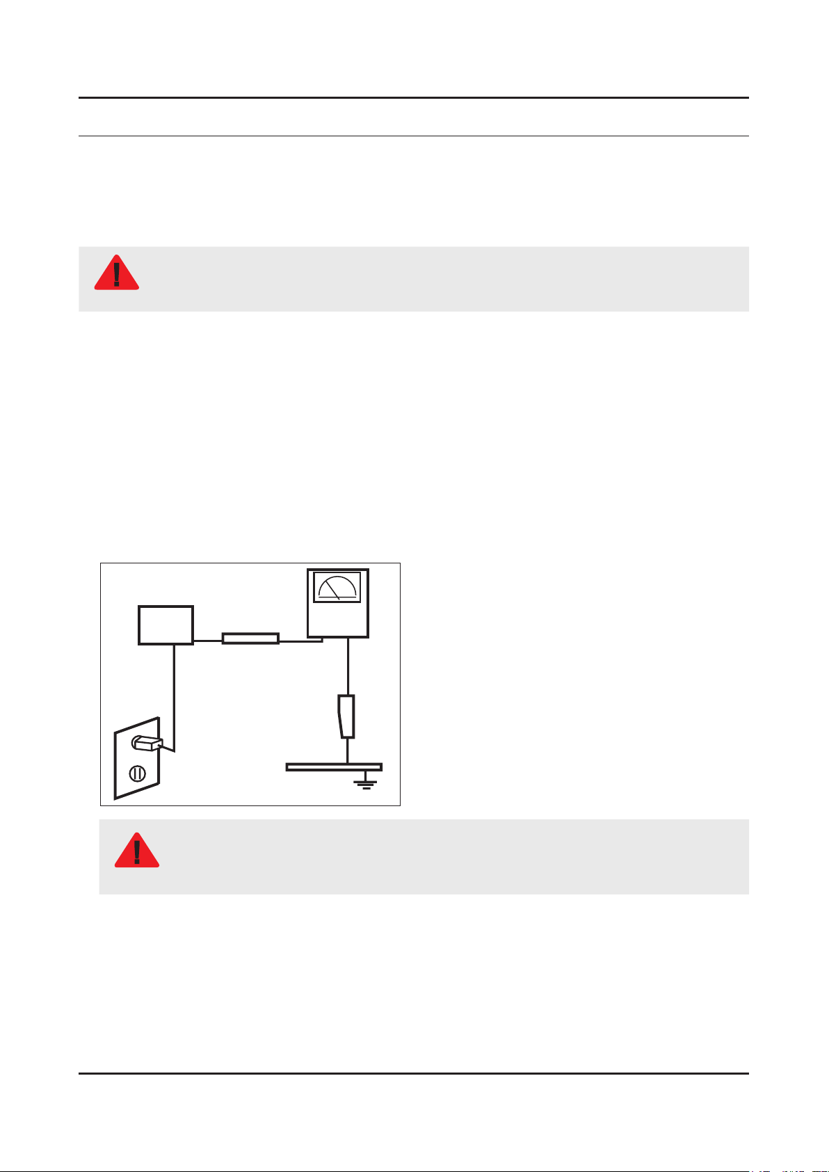
Leakage Current Hot Check:3.
Disconnect the AC power and DC power jack before servicing.
(READING SHOULD)
DEVICE
UNDER
TEST
ALSO TEST WITH
PLUG REVERSED
(USING AC ADAPTER
PLUG AS REQUIRED)
NOT BE ABOVE 0.5mA
2-WIRE CORD
TEST ALL
EXPOSED METAL
SURFACES
LEAKAGE
CURRENT
TESTER
EARTH
GROUND
Do not use an isolation transformer during this test.
Use a leakage current tester or a metering system that complies with American National Standards
WARNING
Institute (ANSI C101.1, Leakage Current for Appliances), and Underwriters Laboratories (UL
Publication UL1410, 59.7).
With the unit completely reassembled, plug the AC line cord directly into a 120V AC outlet. With the unit’s AC switch rst 4.
in the ON position and then OFF, measure the current between a known earth ground (metal water pipe, conduit, etc.)
and all exposed metal parts, including: metal cabinets, screwheads and control shafts.
The current measured should not exceed 0.5 milliamp.
Reverse the power-plug prongs in the AC outlet and repeat the test.
1-1

1-2
1. Precautions
1-1-4. Product Safety Notices
Some electrical and mechanical parts have special safetyrelated characteristics which are often not evident from visual
inspection. The protection they give may not be obtained by replacing them with components rated for higher voltage,
wattage, etc. Parts that have special safety characteristics are identied by on schematics and parts lists. A substitute
replacement that does not have the same safety characteristics as the recommended replacement part might create
shock, re and/or other hazards. Product safety is under review continuously and new instructions are issued whenever
appropriate.
1-3
1. Precautions
1-2. Servicing Precautions
An electrolytic capacitor installed with the wrong polarity might explode.
WARNING
Before servicing units covered by this service manual, read and follow the Safety Precautions section of
CAUTION
NOTE
1-2-1. General Servicing Precautions
Always unplug the unit’s AC power cord from the AC power source and disconnect the DC Power Jack before 1.
attempting to: (a) remove or reinstall any component or assembly, (b) disconnect PCB plugs or connectors, (c) connect
a test component in parallel with an electrolytic capacitor.
Some components are raised above the printed circuit board for safety. An insulation tube or tape is sometimes used. 2.
The internal wiring is sometimes clamped to prevent contact with thermally hot components. Reinstall all such elements
to their original position.
After servicing, always check that the screws, components and wiring have been correctly reinstalled. Make sure that 3.
the area around the serviced part has not been damaged.
Check the insulation between the blades of the AC plug and accessible conductive parts (examples: metal panels, input 4.
terminals and earphone jacks).
Insulation Checking Procedure: Disconnect the power cord from the AC source and turn the power switch ON. Connect 5.
an insulation resistance meter (500 V) to theblades of the AC plug. The insulation resistance between each blade of the
AC plug and accessible conductive parts (see above) should be greater than 1 megohm.
Always connect a test instrument’s ground lead to the instrument chassis ground before connecting the positive lead; 6.
always remove the instrument’s ground lead last.
this manual.
If unforeseen circumstances create conict between the following servicing precautions and any of the
safety precautions, always follow the safety precautions.
1-4
1. Precautions
1-3. Static Electricity Precautions
Some semiconductor (solid state) devices can be easily damaged by static electricity. Such components are commonly
called Electrostatically Sensitive Devices (ESD). Examples of typical ESD are integrated circuits and some eld-effect
transistors. The following techniques will reduce the incidence of component damage caused by static electricity.
Immediately before handling any semiconductor components or assemblies, drain the electrostatic charge from your 1.
body by touching a known earth ground. Alternatively, wear a discharging wrist-strap device. To avoid a shock hazard,
be sure to remove the wrist strap before applying power to the monitor.
After removing an ESD-equipped assembly, place it on a conductive surface such as aluminum foil to prevent 2.
accumulation of an electrostatic charge.
Do not use freon-propelled chemicals. These can generate electrical charges sufcient to damage ESDs.3.
Use only a grounded-tip soldering iron to solder or desolder ESDs.4.
Use only an anti-static solder removal device. Some solder removal devices not classied as “anti-static” can generate 5.
electrical charges sufcient to damage ESDs.
Do not remove a replacement ESD from its protective package until you are ready to install it. Most replacement ESDs 6.
are packaged with leads that are electrically shorted together by conductive foam, aluminum foil or other conductive
materials.
Immediately before removing the protective material from the leads of a replacement ESD, touch the protective material 7.
to the chassis or circuit assembly into which the device will be installed.
Be sure no power is applied to the chassis or circuit and observe all other safety precautions.
CAUTION
Minimize body motions when handling unpackaged replacement ESDs. Motions such as brushing clothes together, or 8.
lifting your foot from a carpeted oor can generate enough static electricity to damage an ESD.
1-5
1. Precautions
1-4. Installation Precautions
For safety reasons, more than a people are required for carrying the product.1.
Keep the power cord away from any heat emitting devices, as a melted covering may cause re or electric shock.2.
Do not place the product in areas with poor ventilation such as a bookshelf or closet. The increased internal temperature 3.
may cause re.
Bend the external antenna cable when connecting it to the product. This is a measure to protect it from being exposed 4.
to moisture. Otherwise, it may cause a re or electric shock.
Make sure to turn the power off and unplug the power cord from the outlet before repositioning the product. Also check 5.
the antenna cable or the external connectors if they are fully unplugged. Damage to the cord may cause re or electric
shock.
Keep the antenna far away from any high-voltage cables and install it rmly. Contact with the highvoltage cable or the 6.
antenna falling over may cause re or electric shock.
When installing the product, leave enough space (0.4m) between the product and the wall for ventilation purposes. 7.
A rise in temperature within the product may cause re.
If an equipment is provided with a replaceable battery, and if replacement by an incorrect type could result in an 8.
explosion (for example, with some lithium batteries), the following applies:
Risk of explosion if battery is replaced by an incorrect type dispose of used batteries according to •
the instructions.
Do not dispose of batteries in a re.•
Do not short circuit, disassemble or overheat the batteries.•
CAUTION
Danger of explosion if battery is incorrectly replaced. Replace only with the same or equivalent •
type.
Do not be exposed to excessive heat such as sunshine, re or the like.•
2. Product Specications
2-1. Product information
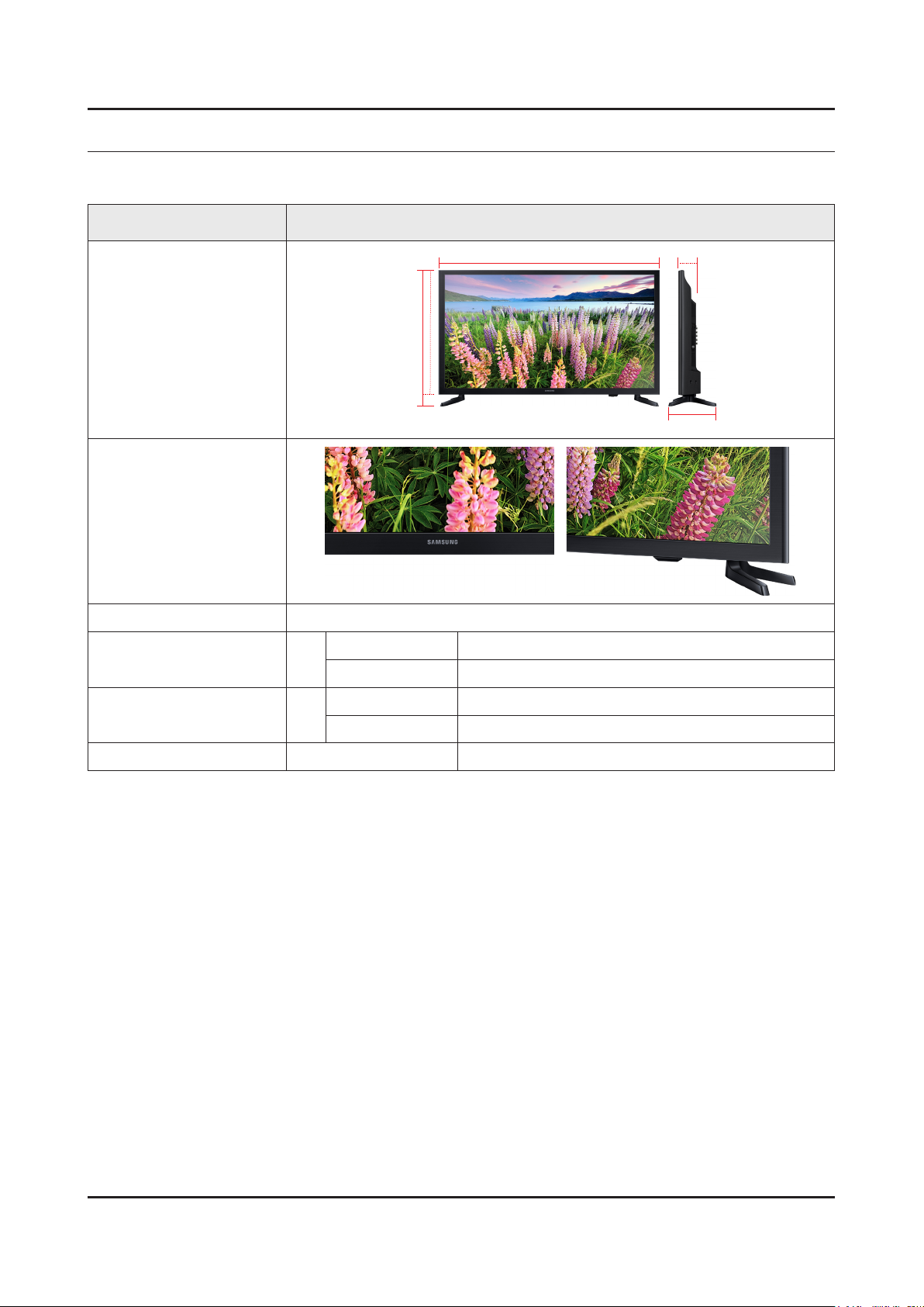
Model UN32J525DAF
2. Product specications
W
Front View
Detail View
Color Front : TITAN BLACK(HAIRLINE), Stand : TITAN BLACK
Dimensions
(W x H x D)
Weight 32"
Panel Type All Slim LED
32"
With Stand 741.0 x 468.7 x 145.5 mm
Without Stand 741.0 x 436.0 x 69.0 mm
With Stand 3.9 kg
Without Stand 3.8 kg
H
* W : Width H : High D : Depth
D
2-1
2-2
2. Product specications
2-2. Product specication
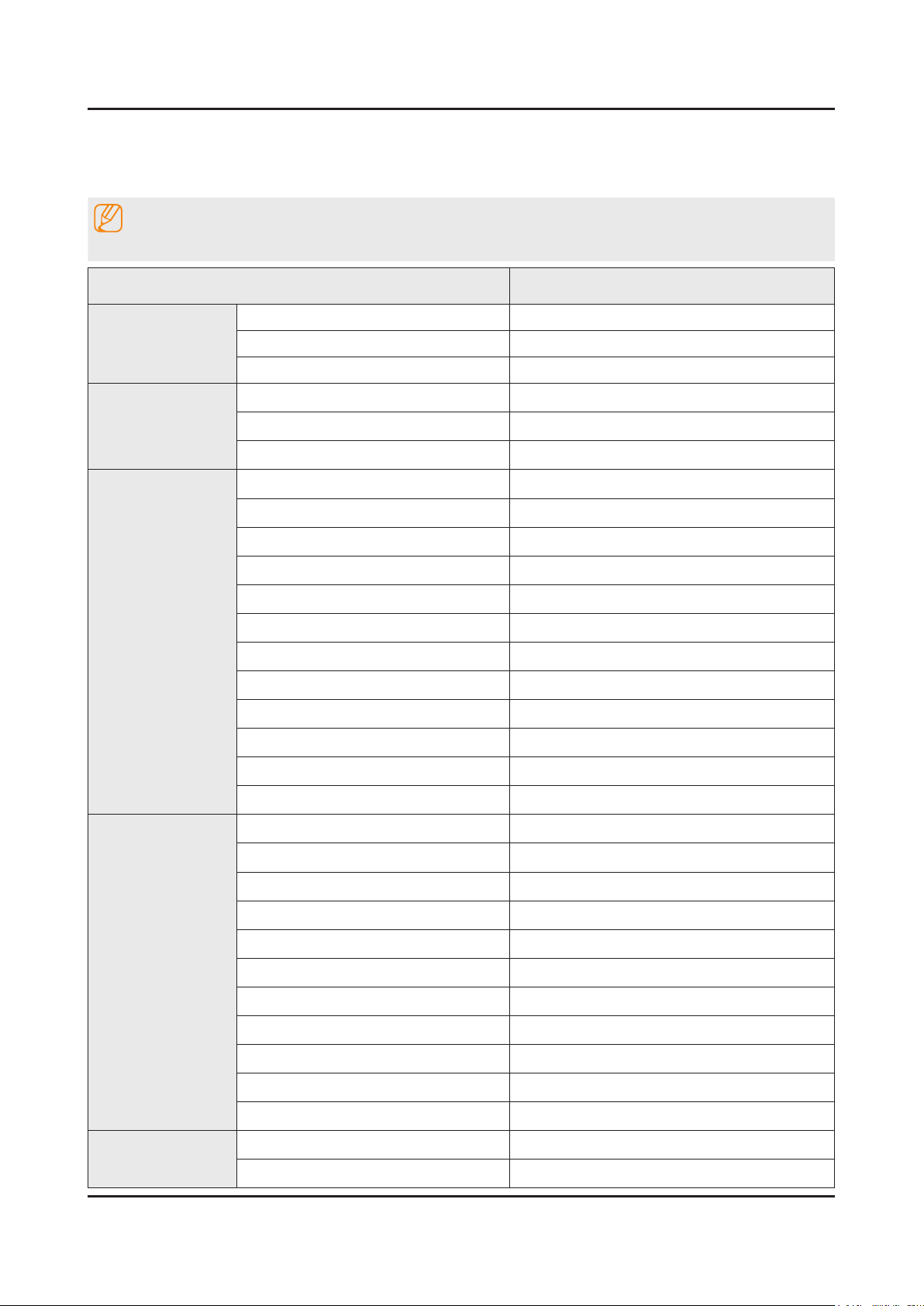
2-2-1. Detailed Specications
NOTE
Design and specications are subject to change without prior notice.
Item UN32J525DAFXZA
General Information
Display
Video
Product LED
Series 4
Country UNITED STATES
Screen Size 32"
Resolution 1,920 x 1,080
Ultra Clear Panel N/A
Motion Rate 60Hz
Dynamic Contrast Ratio Mega Contrast
Micro Dimming N/A
Precision Black (Local Dimming) N/A
Nano Crystal Color N/A
Wide Color Enhancer (Plus) Yes
PurColor N/A
Auto Depth Enhancer N/A
Contrast Enhancer N/A
Auto Motion Plus N/A
Audio
Smart TV
Film Mode Yes
Peak Illuminator N/A
Dolby Digital Plus Yes
Virtual Surround DTS Studio Sound
DTS Codec DTS Premium Sound
3D Sound N/A
Sound Customizer N/A
Sound Output (RMS) 10W(5W+5W)
Speaker Type Down Firing + Base Reex
Woofer N/A
HD Audio N/A
Wallmount Sound Mode Yes
Multiroom Link N/A
Samsung SMART TV Yes
Apps Yes
2-3
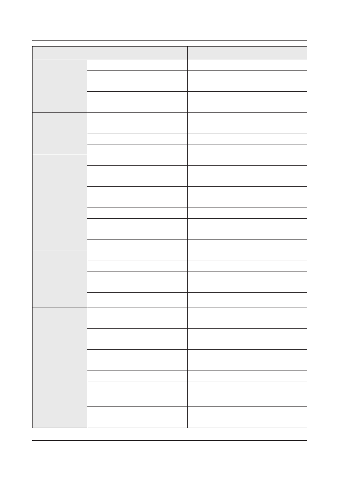
2. Product specications
Item UN32J525DAFXZA
Smart TV
Smart Interaction
Convergence
Games N/A
Multi-Link Screen N/A
Automated Content Recognition (ACR) Yes (US Only)
Info Widget N/A
Vertical Enhancement N/A
Voice Interaction N/A
Voice Control N/A
Face recognition N/A
Motion control N/A
TV to Mobile - Mirroring N/A
Mobile to TV - Mirroring, DLNA Yes
RVU N/A
Samsung SMART View N/A
Wireless TV On - Samsung WOL N/A
Notication - BLE N/A
Brieng On TV N/A
Tuner/Broadcasting
Connectivity
WiDi N/A
WiFi Direct Yes
Digital Broadcasting ATSC / Clear QAM
2 Tuner N/A
CI/CI+/2CI+ N/A
Analog Tuner Yes
MHP / MHEG / HbbTV / ACAP / GINGA /
OHTV
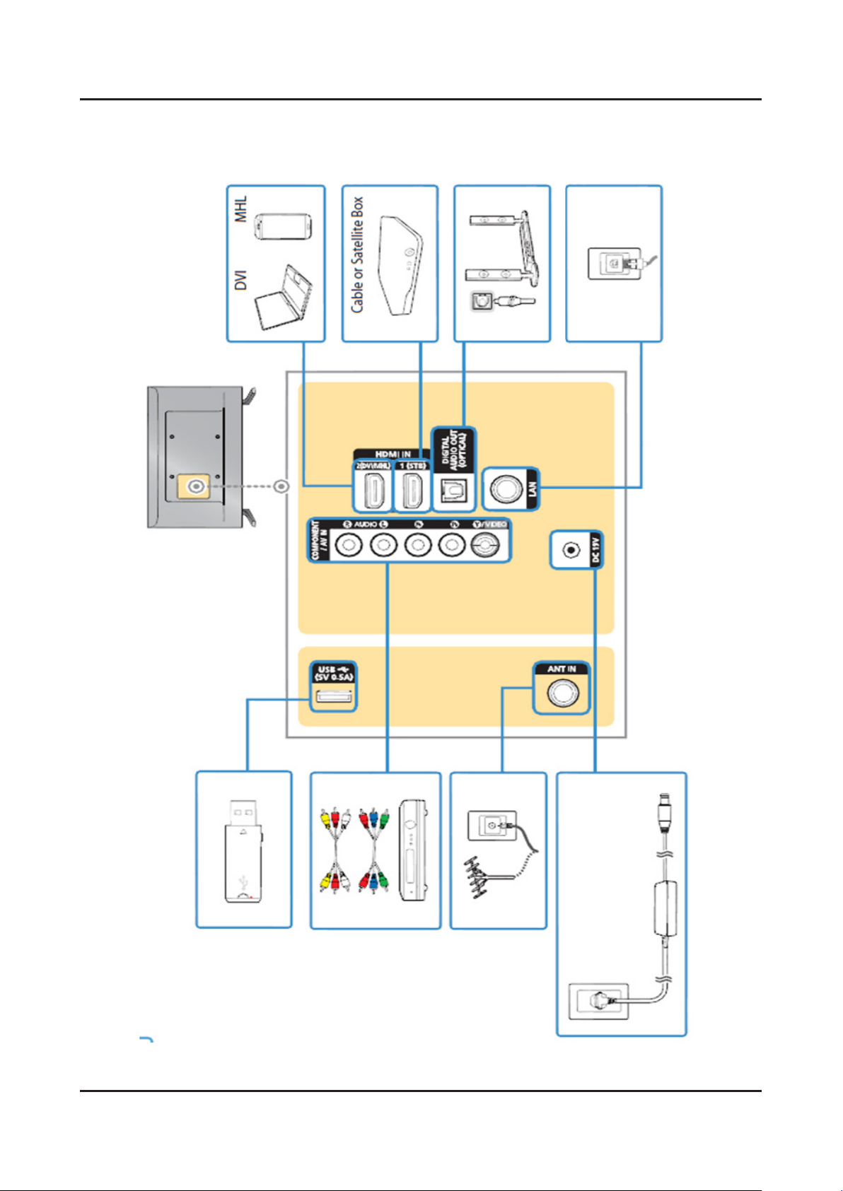
HDMI 2
USB 1
Component In (Y/Pb/Pr) 1
Composite In (AV) 1(Common Use for Component Y)
Ethernet (LAN) 1
Headphone N/A
Audio Out (Mini Jack) N/A
Digital Audio Out (Optical) 1
RF In (Terrestrial / Cable input / Satellite
input)
Ex-Link ( RS-232C ) N/A
1/1(Common Use for Terrestrial)/0
N/A
IR Out N/A
2-4
2. Product specications
Item UN32J525DAFXZA
Connectivity
Design
CI Slot N/A
Scart N/A
MHL Yes
Dongle Ready (3G / LTE) N/A
HDMI 3D Auto Setting N/A
HDMI A / Return Ch. Support N/A
HDMI Quick Switch N/A
Wireless LAN Adapter Support N/A
Wireless LAN Built-in Yes
Anynet+ (HDMI-CEC) Yes
Design Slim Edge Mold
Bezel Type NNB
Slim Type Slim (5x mm)
Front Color Black Hairline
Light Effect (Deco) N/A
Stand Type Y Feet (Metallic Silver-SMT)
Additional Feature
Swivel (Left/Right) N/A
Samsung 3D N/A
3D Converter N/A
Instant On N/A
Camera Built-in N/A
Wireless Copy N/A
Processor N/A
PX Ready N/A
21:9 Immersive Picture Mode N/A
SCSA Support N/A
Accessibility Enlarge/High Contrast
Digital Clean View Yes
One Connect (Jack) N/A
Auto Channel Search Yes
Auto Power Off Yes
BD Wise Plus N/A
Caption (Subtitle) Yes
Channel List USB-Clone N/A
Connect Share™ (HDD) N/A
2-5
2. Product specications
Item UN32J525DAFXZA
Additional Feature
Connect Share™ Transfer N/A
ConnectShare™ (USB 2.0) Yes
AC/DC TV N/A
Sports Mode Basic
Embeded POP Yes
EPG Yes
Extended PVR N/A
Game Mode Yes
IP Video Closed Caption Yes
OSD Language English, Spanish, French
Picture-In-Picture Yes
BT HID Built-in N/A
USB HID Support Yes
Feature Upgrade (Evolution Kit Ready) N/A
ATSC 3.0 Ready N/A
Teletext (TTX) N/A
Eco Feature
Accessory
Time Shift N/A
Analog Clean View N/A
Ultra Clean View N/A
Energy Star TBD
Eco Sensor No
3D Active Glasses (Included) N/A
Remote Controller Model TM1240A
Batteries (for Remote Control) Yes
Samsung Smart Control (Included) N/A
PX (Included) N/A
Ultra Slim Wall Mount Support N/A
Mini Wall Mount Support Yes
Vesa Wall Mount Support Yes
Floor Stand Support N/A
TV Camera (Included) N/A
IR Extender Cable (Included) N/A
Wireless Keyboard (Included) N/A
Wireless PC Mirroring Dongle (Included) N/A
Composite to Scart Gender (Included) N/A
2-6
2. Product specications
Item UN32J525DAFXZA
Accessory
User Manual Yes
E-Manual Yes
ANT-Cable N/A
Power Cable Yes
Slim Gender Cable N/A
2-7
2. Product specications
2-2-2. Specications
Specications
Model UN32J525DAF
Item Description
Screen Size (Diagonal) 32 inches
LCD Panel FHD 60Hz
Display Colors 16.7M color
Display Resolution 1,920 x 1,080
Input Signal Analog 0.7 Vp-p ± 5% positive at 75Ω, internally terminated
Input Sync Signal H/V Separate, TTL, P. or N.
AC Power Voltage & Frequency AC110-120V 60Hz
Environmental Considerations Operating Temperature: 50˚F ~ 104˚F (10˚C ~ 40˚C)
Operating Humidity: 10% ~ 80%, non-condensing
Storage Temperature: -4˚F ~ 113˚F (-20˚C ~ 45˚C)
Storage Humidity: 5% ~ 95%, non-condensing
Sound (Output) 10W (5W X 2)
2. Product specications
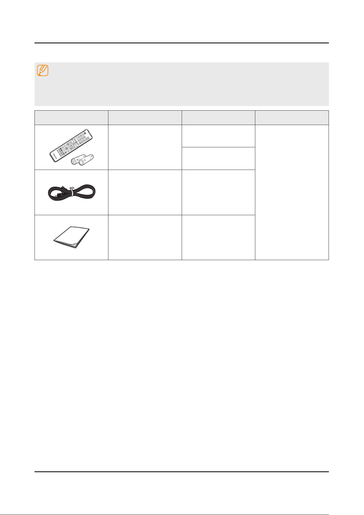
2-3. Accessories
NOTE
The items’ colors and shapes may vary depending on the model.•
Cables not included in the package contents can be purchased separately.•
The part code for some accessories may differ depending on your region.•
Product Description Code. No Remark
Remote Control &
Batteries
(AAA x 2)
Power Cord 3903-000853
Manual Users BN68-07181A
BN59-01199F
4301-000121
-
2-8
3. Disassembly and Reassemble
3. Disassembly and Reassembly
This section of the service manual describes the disassembly and reassembly procedures for the LED TV.
This LED TV contains electrostatically sensitive devices. Use caution when handling these components.
WARNING
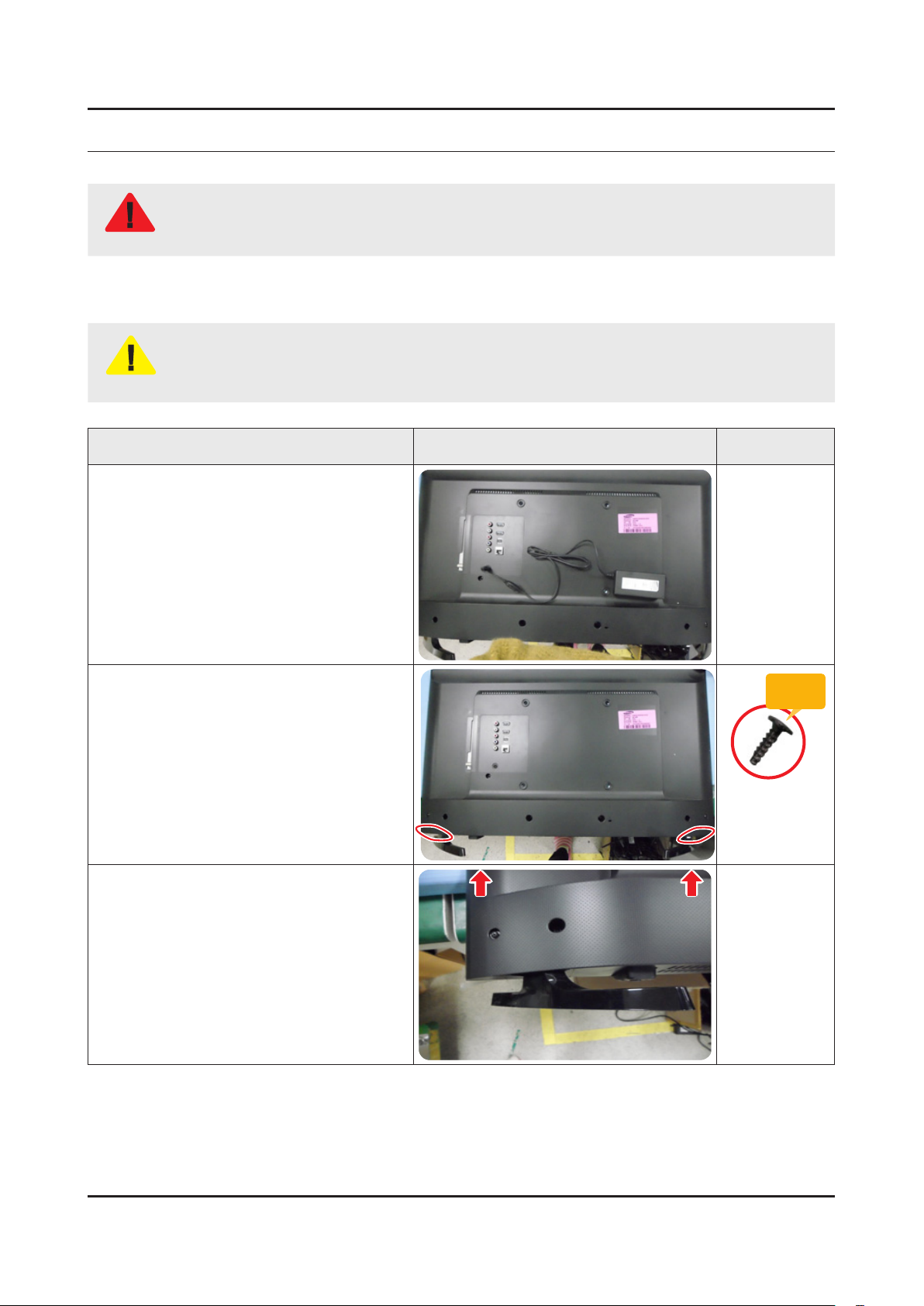
3-1. Disassembly and Reassembly
Disconnect the LED TV from the power source before disassembly.1.
Follow these directions carefully; never use metal instruments to pry apart the cabinet.2.
CAUTION
Place TV face down on cushioned table.
If there is no additional coment, it is same for all inches.3.
Description Picture Description Screws
1
Remove the DC VSS(A) and 4 Screws
2
from the ASSY STAND P-BASE.
Remove the ASSY STAND P-BASE.
3
Torque :
9~ 10Kgf.cm
6003-001782
1
2
3. Disassembly and Reassemble
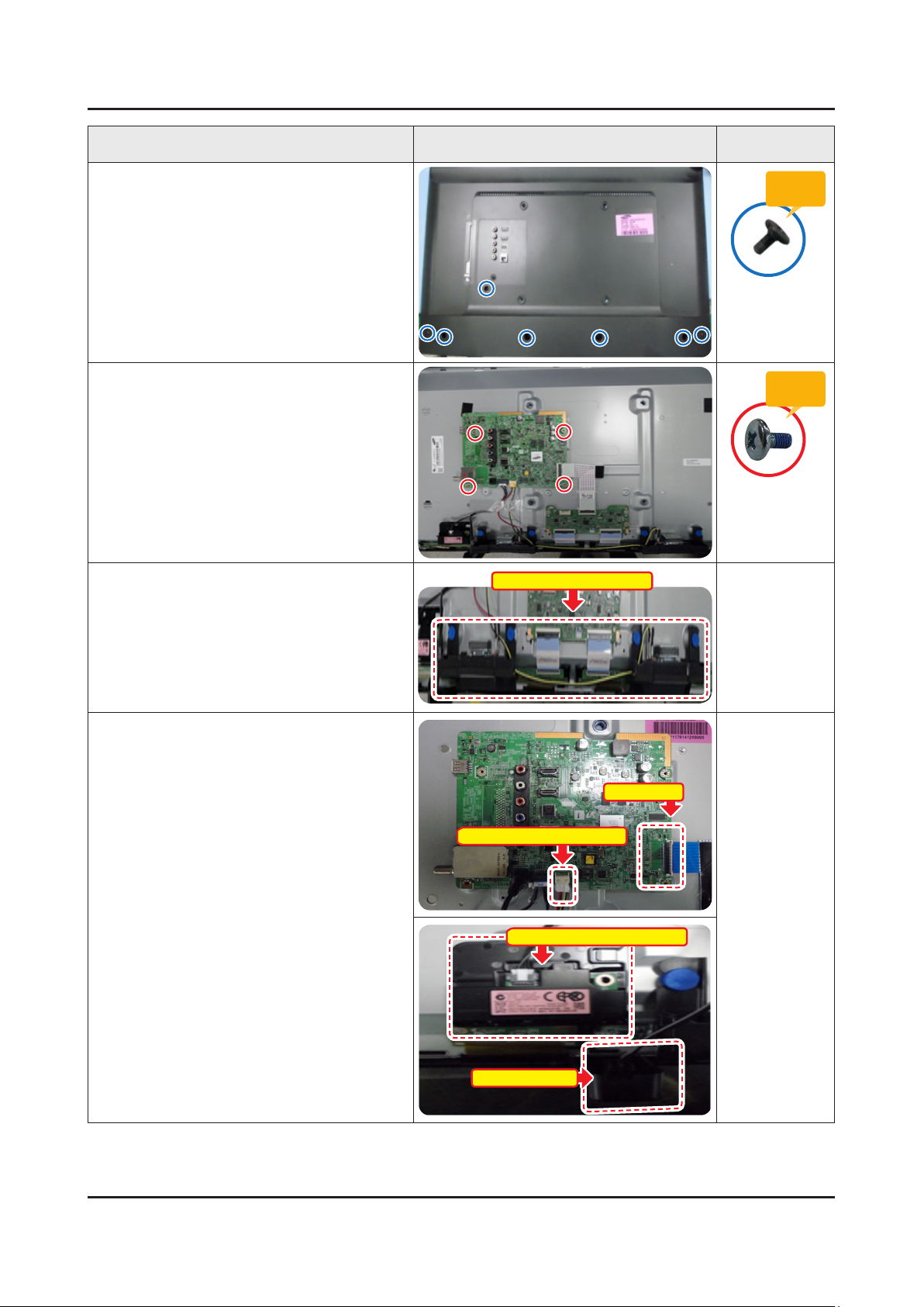
Description Picture Description Screws
Remove screws of COVER-REAR.
4
7EA•
Remove 4 Screws of ASSY PCB MAIN.
5
Remove the ASSY SPEAKER P (R/L).
6
ASSY SPEAKER P (R/L)
Torque :
7~ 8Kgf.cm
6003-002755
Torque :
7~ 8Kgf.cm
6001-003016
Remove the LVDS Cable, NETWORK-WI-
7
FI MODULE and ASSY BOARD P.
LVDS Cable
ASSY SPEAKER P Cable
NETWORK-WI-FI MODULE
ASSY BOARD P
3
3. Disassembly and Reassemble
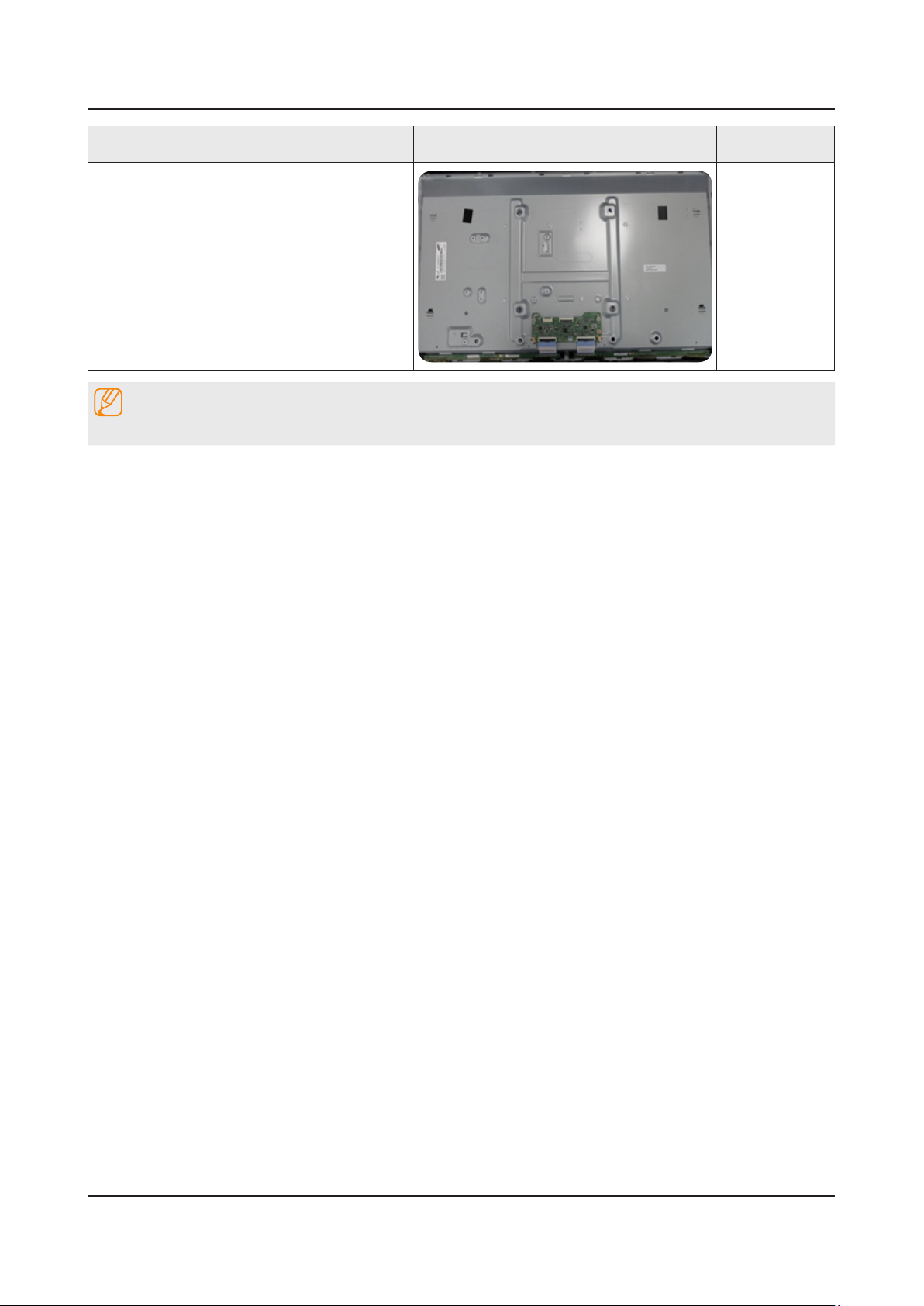
Description Picture Description Screws
Completed disassembly.
8
NOTE
Reassembly procedures are in the reverse order of disassembly procedures.
3. Disassembly and Reassemble
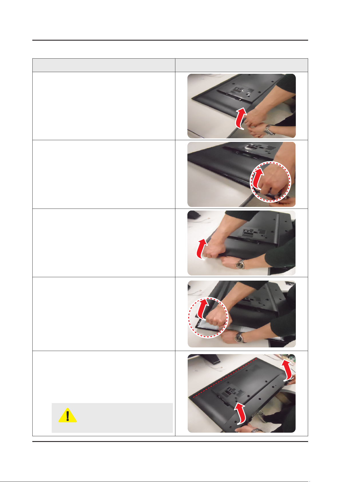
3-2. Disassembly and Reassembly_COVER-REAR
Description Picture Description
Pull the Lower left(or right) corner of COVER-
1
REAR.
Opened that point.
2
Pull the upper left(or right) corner of COVER-REAR.
3
Opened that point.
4
4
CAUTION
Don’t disassemble only using lower
two point.
It cause the breakage of RIB(panel).
4. Troubleshooting
4-1. Troubleshooting
Previous Check
Check the various cable connections rst.1.
Check to see if there is a burnt or damaged cable. -
Check to see if there is a disconnected or loose cable connection. -
Check to see if the cables are connected according to the connection diagram. -
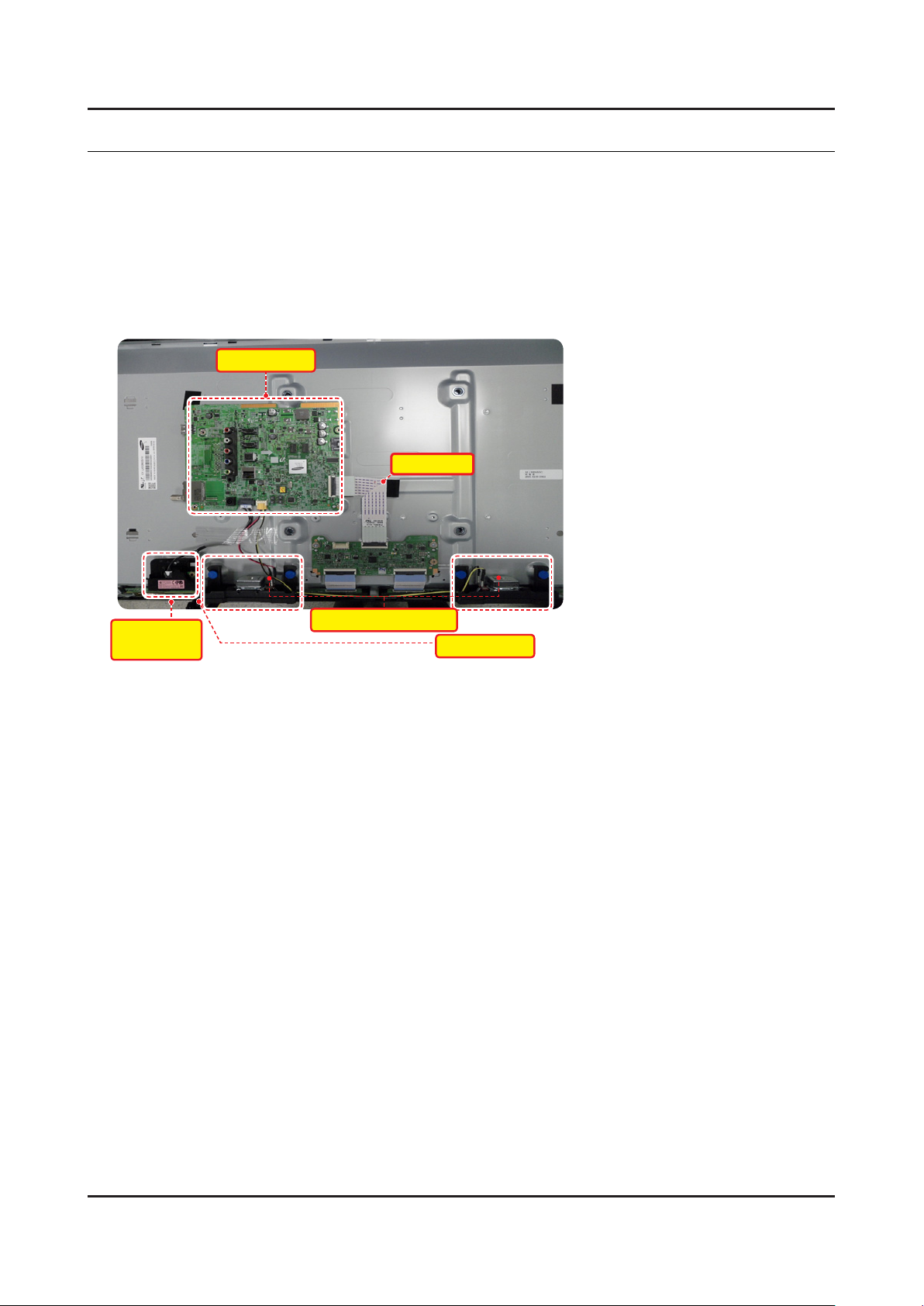
Check the power input to the 2. ASSY PCB MAIN Board.
ASSY PCB MAIN
4. Troubleshooting
LVDS Cable
NETWORK-
WI-FI MODULE
Check the power in & output between DC VSS(A) (3. Adaptor) & ASSY PCB MAIN, ASSY PCB MAIN & Panel, IP & Panel.
ASSY SPEAKER P (R/L)
ASSY BOARD P
4-1
4-2
4. Troubleshooting
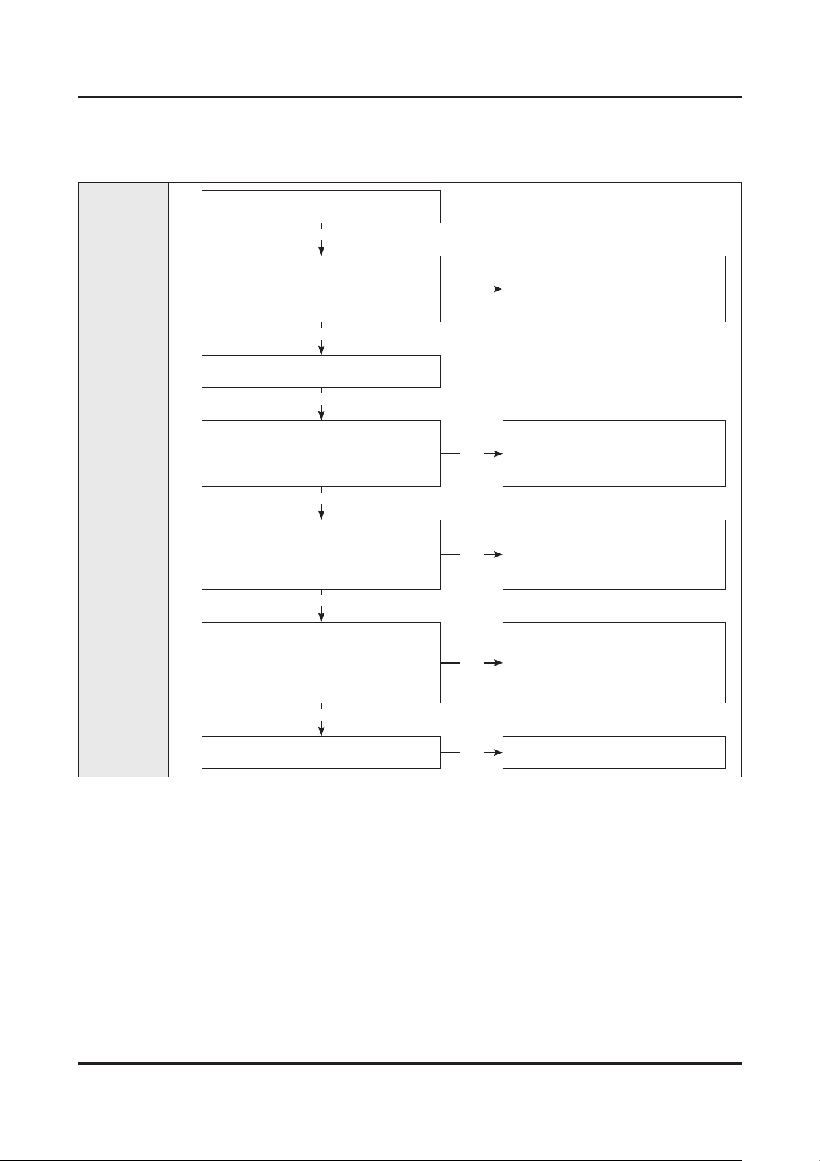
4-2. How to Check Fault Symptom
No Picture
Power cord on.
Yes
Diagnostics
Check ‘Stand-By 19V’
19V appear at BD210?
0V to A19V (CN202 #1)
Yes
Set On.
Yes
Check ‘SW_POWER’ more than 3.3V
appear at C274
0V to 3.3V↑ (C274)
Yes
Check ‘Power of CORE IC(B1.15V)’
appear at BD301.
Check ‘Power of DDR IC(B1.5V)’ appear
at BD1120
Yes
Check ‘Power of LVDS (13V)’
appear at TP-PANEL_VCC?
0V to 13V (TP-PANEL_VCC)
No
No
No
No
Cause : There did not supply the
power from Adaptor.
Measure : Change Adaptor.
Cause : Main IC(NT14M) did not
control the SW_Power.
Measure : Change the
Cause : There is problem at IC301/
IC203.
Measure : Change the
Cause : There is proble at FET(Q301)
or Main IC(NT14M) did not
control the SW_PVCC.
Measure : Change the
ASSY PCB MAIN.
ASSY PCB MAIN.
ASSY PCB MAIN.
Yes
Change the LVDS cable ?
No
Change the Panel.
4-3
4. Troubleshooting
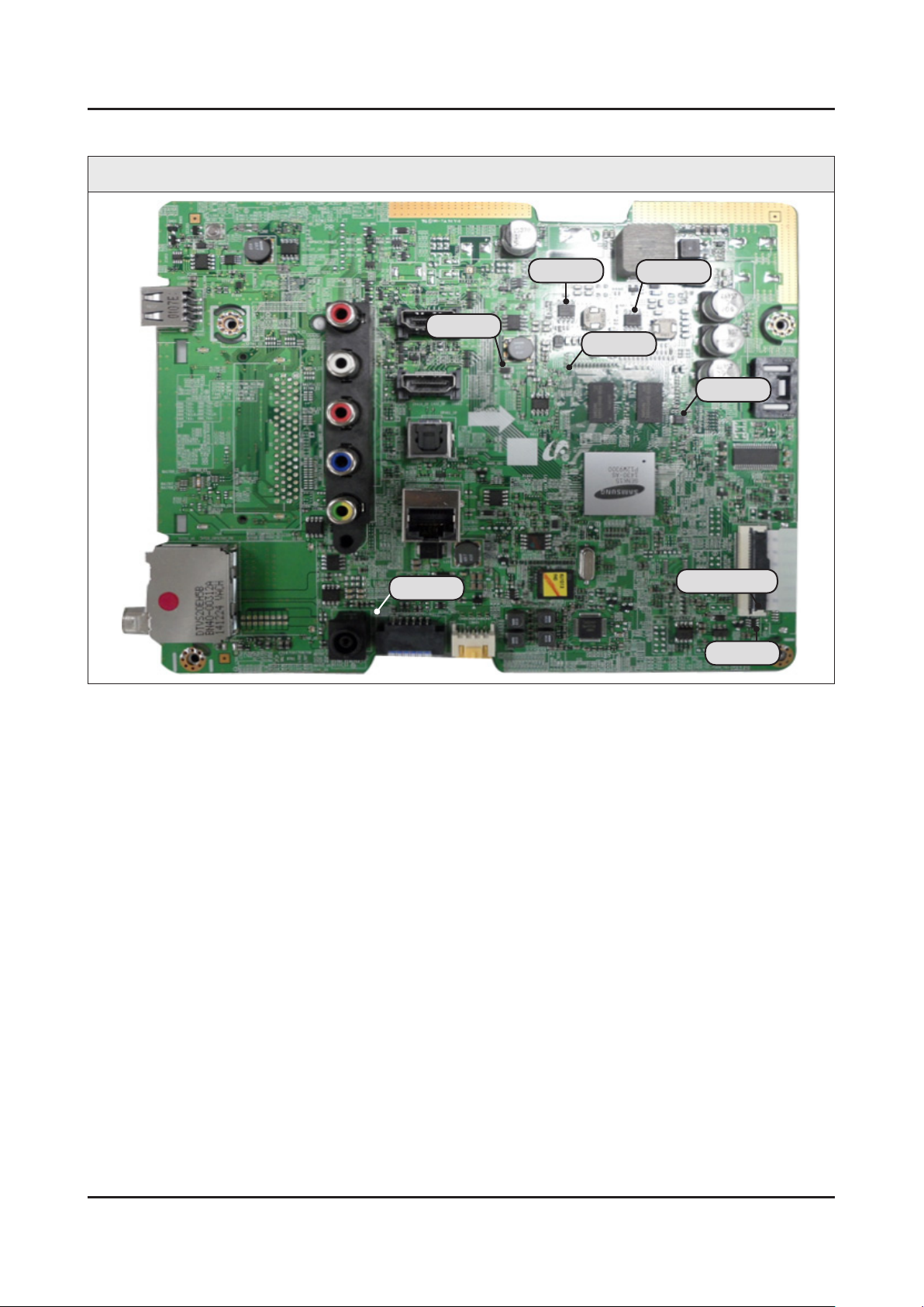
Location of Parts
Main Board_Front
BD201
C274
IC203
IC301
BD1120
BD301
PANEL_VCC
Q301
4-4
4. Troubleshooting
4-3. Connect
4-4. Factory Mode Adjustments
4-5
4. Troubleshooting
4-4-1. Detail Factory Option
NOTE
If you replace the main board with new one, please change the factory option as well.
The options you must change are "Type".
UN32J525DAFXZA
32"
Inches
TS01 LS02 LS03
Vendor SDC CORETN CORETN
PANEL
SMPS BOARD
(DC VSS(A),
Adaptor)
MAIN BOARD
Byte Item
0 Factory Reset -
1 Type 32A6AF0JJ 32A6AF0JJ 32B6AF0JJ
2 Local set US
3 SW Model UJ525D
4 BOM Model 525D
5 Tuner ATSC / Clear QAM
6 Ch table NONE
Code BN95-02130B BN07-01458B BN07-01423B
Spec. CY-JJ032BGLV2V/H JJ032BGL-R2 JJ032BGE-R2
Vendor SEM SEM SEM
Code BN44-00837A BN44-00837A BN44-00837A
Spec. A6619_FSM A6619_FSM A6619_FSM
Chassis Ass'y BN91-14720H BN91-14720H BN91-14203A
PBA Ass'y BN94-08236W BN94-08236W BN94-08227A
4-6
4. Troubleshooting
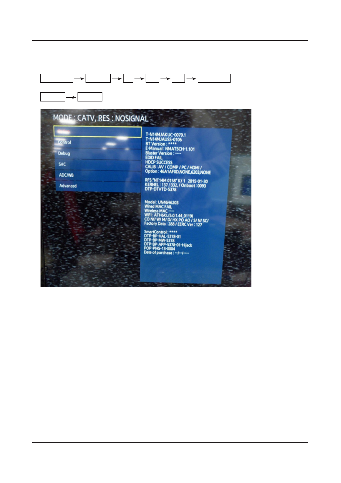
4-4-2. Entering Factory Mode
To enter ‘Service Mode’ Press the remote -control keys in this sequence :
If you do not have Factory remote control•
Power OFF MENU 1 8 2 Power ON
If you have Factory remote control•
INFO Factory
If you don’t have Factory remote control, can’t control some menus. •
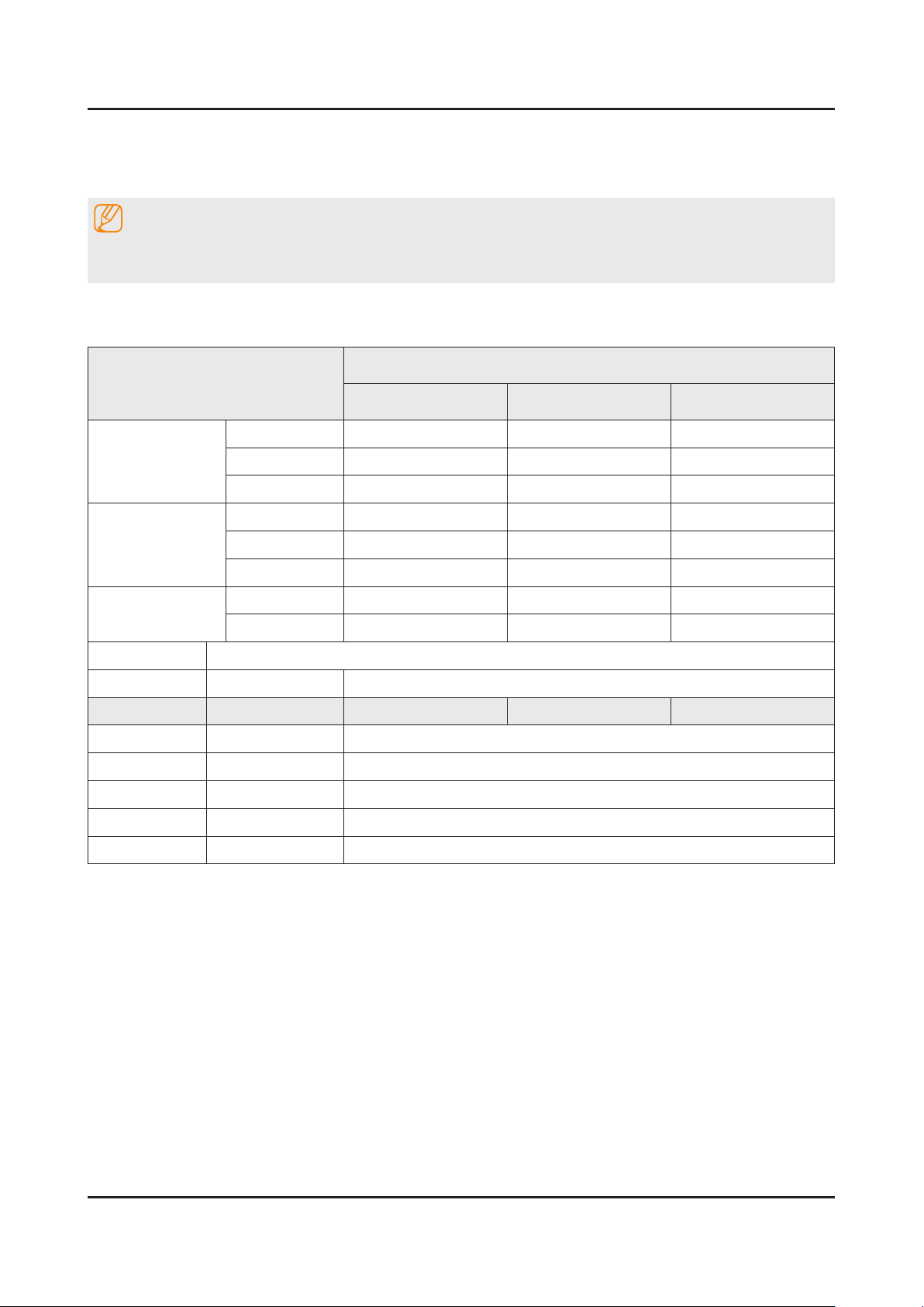
4-4-3. Factory Data
4-7
4. Troubleshooting
Option
Factory Menu Name Data Range
Factory Reset
Factory Reset 32S6AH0JJ 32A6AF0JJ(SDC) / 32BAF0JJ(BOE)
Type
Local Set
Model
SVC Model
TUNER NONE
Ch Table
-
Depending on models
UJ5205
5205
Depending on models
UJ5205
MRT Option
Front Color U-S-C-53
Lvds Format JEIDA
Language_Arabic US
Region USA
PnP Language ENG_US
WIFI REGION S
OTN Support ON
OTA Support OFF
MediaPlay DLNA …
TTX OFF
China HD OFF
NT Conversion OFF
Num of DTV 1
Num of AV 1
Num of COMP 1
Num of HDMI 2
Num of SCART 0
Num of USB Port 2
Num of USB 3.0 0
Num of RVU 0
Num of Display 2
Num of IPTV 0
Num of RUI 0
Num of PVR RECORD 0
TOOLS Support 40
LNA Support OFF
 Loading...