

Page 1
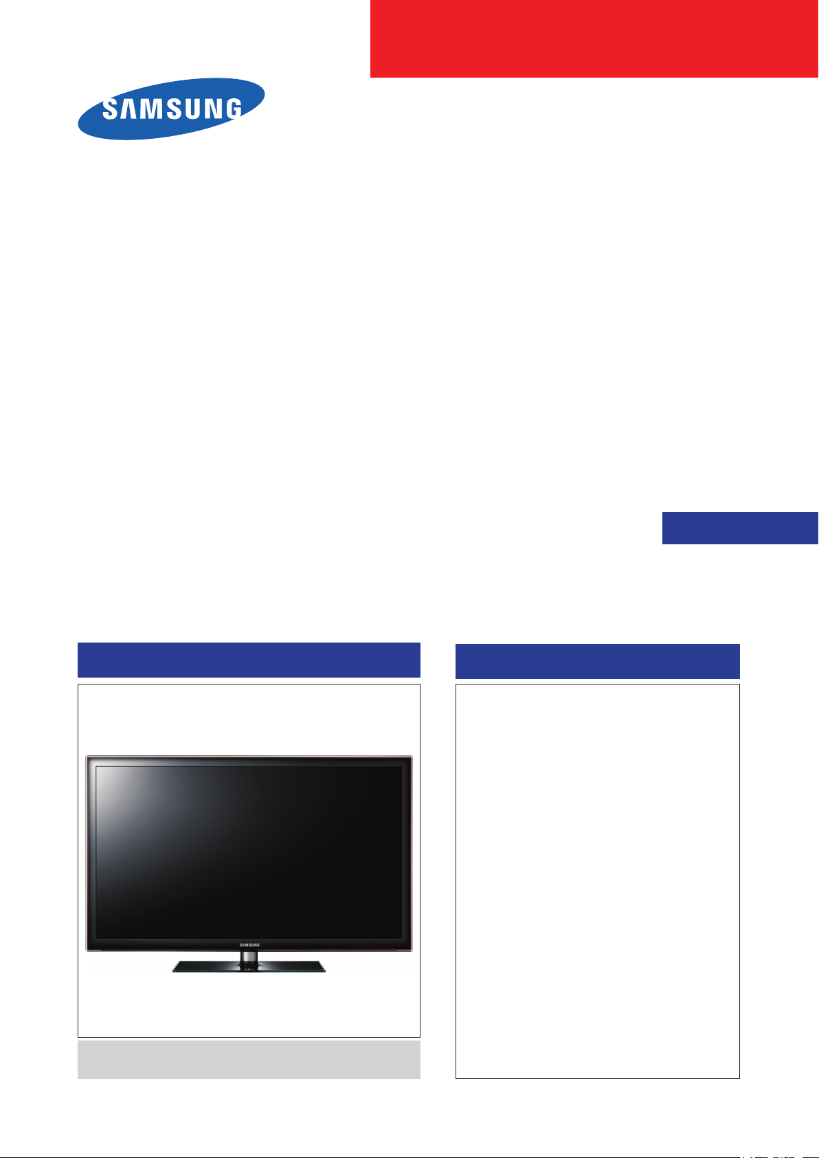
LED-TV
Chassis: U59A
Model :
UN32D5500RF
UN40D5500RF
SERVICE
Manual
TFT-LED TV
Front Design : ToC Charcoal Black Stand : Square
Contents
1. Precautions
2. Product specications
3. Disassembly and Reassembly
4. Troubleshooting
5. Wiring Diagram
UN**D5500RF
Page 2

Contents
1. Precautions .............................................................................................................. 1-1
1-1. Safety Precautions ......................................................................................................... 1-1
1-2. Servicing Precautions ..................................................................................................... 1-2
1-3. Electrostatically Sensitive Devices (ESD) Precautions .................................................. 1-2
1-4. Installation Precautions .................................................................................................. 1-3
2. Product specications ............................................................................................ 2-1
2-1. Specications ................................................................................................................. 2-1
2-2. Detail Factory Option ...................................................................................................... 2-5
2-3. New Features explanation .............................................................................................. 2-6
2-4. Accessories .................................................................................................................. 2-15
3. Disassembly and Reassembly ............................................................................... 3-1
3-1. Disassembly and Reassembly ....................................................................................... 3-1
4. Troubleshooting ...................................................................................................... 4-1
4-1. Troubleshooting .............................................................................................................. 4-1
4-2. Factory Mode Adjustments ........................................................................................... 4-25
4-3. White Balance - Calibration .......................................................................................... 4-37
4-4. White Ratio (Balance) Adjustment ................................................................................4-39
4-5. RS-232C ....................................................................................................................... 4-40
4-6. AV control code ............................................................................................................. 4-41
4-7. Software Upgrade ......................................................................................................... 4-46
4-8. Rear Cover Dimension ................................................................................................. 4-49
5. Wiring Diagram ........................................................................................................ 5-1
5-1. Wiring Diagram ............................................................................................................... 5-1
5-2. Position of Connector ..................................................................................................... 5-2
5-3. Connector Functions ...................................................................................................... 5-5
5-4. Cables ............................................................................................................................ 5-5
Page 3
This Service Manual is a property of Samsung Electronics Co.,Ltd.
Any unauthorized use of Manual can be punished under applicable
International and/or domestic law.
© 2011 Samsung Electronics Co.,Ltd.
All rights reserved.
Printed in Korea
Page 4
1. Precautions
1. Precautions
1-1. Safety Precautions
Follow these safety, servicing and ESD precautions to prevent damage and to protect against potential hazards such as
electrical shock.
1-1-1. Warnings
For continued safety, do not attempt to modify the circuit board.1.
Disconnect the AC power and DC power jack before servicing.2.
1-1-2. Servicing the LED TV
When servicing the LED TV, Disconnect the AC line cord from the AC outlet.1.
It is essential that service technicians have an accurate voltage meter available at all times. 2.
Check the calibration of this meter periodically.
1-1-3. Fire and Shock Hazard
Before returning the LED TV to the user, perform the following safety checks:
Inspect each lead dress to make certain that the leads are not pinched or that hardware is not lodged between the 1.
chassis and other metal parts in the LED TV.
Inspect all protective devices such as nonmetallic control knobs, insulating materials, cabinet backs, adjustment and 2.
compartment covers or shields, isolation resistorcapacitor networks, mechanical insulators, etc.
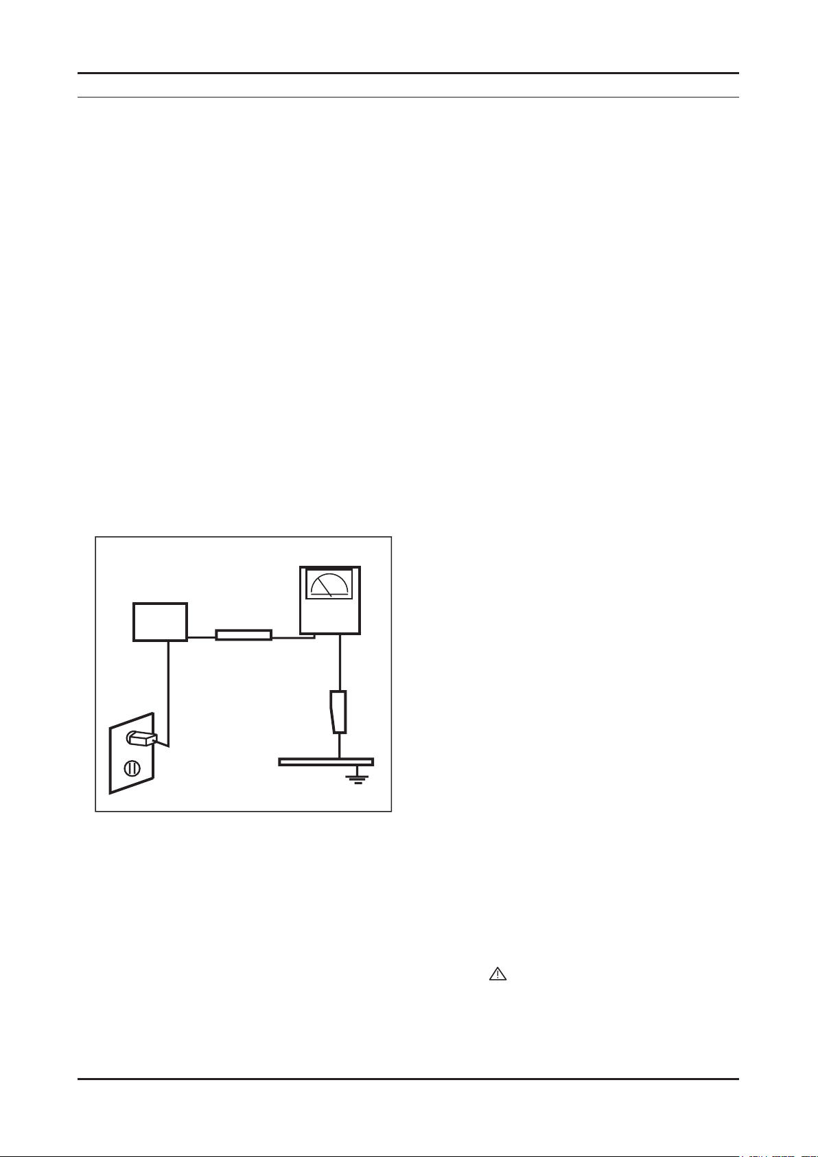
Leakage Current Hot Check (Figure 1-1): 3.
WARNING : Do not use an isolation transformer during this test.
Use a leakage current tester or a metering system that complies with American National Standards Institute (ANSI
C101.1, Leakage Current for Appliances), and Underwriters Laboratories (UL Publication UL1410, 59.7).
(READING SHOULD)
NOT BE ABOVE 0.5mA
DEVICE
UNDER
TEST
2-WIRE CORD
*ALSO TEST WITH
PLUG REVERSED
(USING AC ADAPTER
PLUG AS REQUIRED)
TEST ALL
EXPOSED METAL
SURFACES
LEAKAGE
CURRENT
TESTER
EARTH
GROUND
Figure 1-1. Leakage Current Test Circuit
With the unit completely reassembled, plug the AC line cord directly into a 120V AC outlet. With the unit’s AC switch 4.
rst in the ON position and then OFF, measure the current between a known earth ground (metal water pipe, conduit,
etc.) and all exposed metal parts, including: metal cabinets, screwheads and control shafts.
The current measured should not exceed 0.5 milliamp.
Reverse the power-plug prongs in the AC outlet and repeat the test.
1-1-4. Product Safety Notices
Some electrical and mechanical parts have special safetyrelated characteristics which are often not evident from visual
inspection. The protection they give may not be obtained by replacing them with components rated for higher voltage,
wattage, etc. Parts that have special safety characteristics are identied by
replacement that does not have the same safety characteristics as the recommended replacement part might create
shock, re and/or other hazards. Product safety is under review continuously and new instructions are issued whenever
appropriate.
on schematics and parts lists. A substitute
1-1
Page 5

1-2
1. Precautions
1-2. Servicing Precautions
WARNING: An electrolytic capacitor installed with the wrong polarity might explode.
Caution: Before servicing units covered by this service manual, read and follow the Safety Precautions section of
this manual.
Note: If unforeseen circumstances create conict between the following servicing precautions and any of the
safety precautions, always follow the safety precautions.
1-2-1 General Servicing Precautions
Always unplug the unit’s AC power cord from the AC power source and disconnect the DC Power Jack before 1.
attempting to:
(a) remove or reinstall any component or assembly, (b) disconnect PCB plugs or connectors, (c) connect a test
component in parallel with an electrolytic capacitor.
Some components are raised above the printed circuit board for safety. An insulation tube or tape is sometimes 2.
used. The internal wiring is sometimes clamped to prevent contact with thermally hot components. Reinstall all such
elements to their original position.
After servicing, always check that the screws, components and wiring have been correctly reinstalled. Make sure that 3.
the area around the serviced part has not been damaged.
Check the insulation between the blades of the AC plug and accessible conductive parts (examples: metal panels, 4.
input terminals and earphone jacks).
Insulation Checking Procedure: Disconnect the power cord from the AC source and turn the power switch ON. 5.
Connect an insulation resistance meter (500 V) to theblades of the AC plug.
The insulation resistance between each blade of the AC plug and accessible conductive parts (see above) should be
greater than 1 megohm.
Always connect a test instrument’s ground lead to the instrument chassis ground before connecting the positive lead; 6.
always remove the instrument’s ground lead last.
1-3. Electrostatically Sensitive Devices (ESD) Precautions
Some semiconductor (solid state) devices can be easily damaged by static electricity. Such components are commonly
called Electrostatically Sensitive Devices (ESD). Examples of typical ESD are integrated circuits and some eld-effect
transistors. The following techniques will reduce the incidence of component damage caused by static electricity.
Immediately before handling any semiconductor components or assemblies, drain the electrostatic charge from your 1.
body by touching a known earth ground. Alternatively, wear a discharging wrist-strap device. To avoid a shock hazard,
be sure to remove the wrist strap before applying power to the LED TV.
After removing an ESD-equipped assembly, place it on a conductive surface such as aluminum foil to prevent 2.
accumulation of an electrostatic charge.
Do not use freon-propelled chemicals. These can generate electrical charges sufcient to damage ESDs.3.
Use only a grounded-tip soldering iron to solder or desolder ESDs.4.
Use only an anti-static solder removal device. Some solder removal devices not classied as “anti-static” can generate 5.
electrical charges sufcient to damage ESDs.
Do not remove a replacement ESD from its protective package until you are ready to install it. Most replacement ESDs 6.
are packaged with leads that are electrically shorted together by conductive foam, aluminum foil or other conductive
materials.
Immediately before removing the protective material from the leads of a replacement ESD, touch the protective 7.
material to the chassis or circuit assembly into which the device will be installed.
Caution: Be sure no power is applied to the chassis or circuit and observe all other safety precautions.
Minimize body motions when handling unpackaged replacement ESDs. Motions such as brushing clothes together, 8.
or lifting your foot from a carpeted oor can generate enough static electricity to damage an ESD.
Page 6

1-3
1. Precautions
1-4. Installation Precautions
For safety reasons, more than a people are required for carrying the product.1.
Keep the power cord away from any heat emitting devices, as a melted covering may cause re or electric shock.2.
Do not place the product in areas with poor ventilation such as a bookshelf or closet. The increased internal 3.
temperature may cause re.
Bend the external antenna cable when connecting it to the product. This is a measure to protect it from being exposed 4.
to moisture. Otherwise, it may cause a re or electric shock.
Make sure to turn the power off and unplug the power cord from the outlet before repositioning the product. Also check 5.
the antenna cable or the external connectors if they are fully unplugged. Damage to the cord may cause re or electric
shock.
Keep the antenna far away from any high-voltage cables and install it rmly. Contact with the highvoltage cable or the 6.
antenna falling over may cause re or electric shock.
When installing the product, leave enough space (0.4m) between the product and the wall for ventilation purposes. 7.
A rise in temperature within the product may cause re.
Page 7
2. Product specications
2-1. Specications
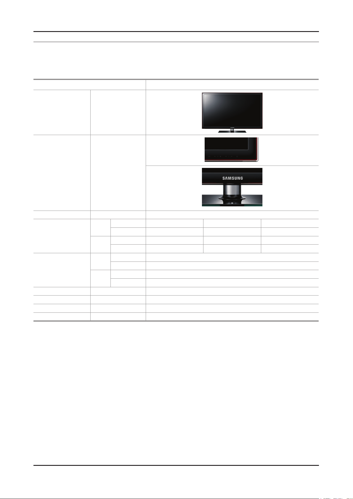
2-1-1. Model Comparison
Model UD5500
Front View All
Detail View All
2. Product specications
Front Color All ToC RED BLK
With Stand 30.2 9.4 20.9
32"
Dimensions
W x D x H (inches)
Weight
(kg / lbs)
Panel Type All Anti Glare
Internal Memory All None
DDR All 384 Mbtye
Feature All Media Play(MOVIE), HDD, DLNA
Without Stand 30.2 1.2 18.4
With Stand 37.6 10.0 25.1
40"
Without Stand 37.6 1.2 22.6
With Stand 9.96 / 21.91
32"
Without Stand 7.22 / 15.88
With Stand 14.36 / 31.59
40"
Without Stand 11.08 / 24.38
2-1
Page 8
2-2
2. Product specications
2-1-2. Feature & Specications
Model UN32D5500RF
Feature
Digital-TV, RF, 4-HDMI, 1-Component, 1-A/V, 2-USB2.0, D-SUB ሪ
Brightness : 450 cd/m ሪ
High Contrast Ratio : 5,000:1 (Marketing spec : 3,000,000:1) ሪ
Response Time : 8 ms (Marketing spec : 8 ms) ሪ
Item Description
LCD Panel 32 inch FHD 60 Hz
Scanning Frequency Horizontal : 60 kHz ~ 73 kHz (Automatic)
Display Colors 16.7 M color
Maximum resolution Horizontal : 1920 Pixels
Input Signal Analog 0.7 Vp-p ± 5% positive at 75Ω, internally terminated
2
(Marketing spec : 500 cd/m2)
Specications
Vertical : 47 Hz ~ 63 Hz (Automatic)
Vertical : 1080 Pixels
Input Sync Signal H/V Separate, TTL, P. or N.
Maximum Pixel Clock rate 74.25MHz
Active Display
Horizontal/Vertical
715.4(H) x 409.5(V) mm / 29.2(H) x 16.7(V) inches
AC power voltage & Frequency AC 110 V ~ 120 V, 60 Hz
Power Consumption Under 80 W (Under 0.3W, Stand by)
Dimensions Set
(W x D x H)
Weight (Set)
768.0 x 240.0 x 530.4(mm) / 30.2 x 9.4 x 20.9(inches) with stand
768.0 x 29.9 x 468.2(mm) / 30.2 x 1.2 x 18.4(inches) without stand
9.96 (kg) / 21.912 (lbs) with stand
7.22 (kg) / 15.884 (lbs) without stand
TV System Tunning Frequency Synthesize (Refer to detailed Frequency Table)
System ATSC & Clear QAM
Sound NTSC-M, Dolby Digital
+
Environmental Considerations Operating Temperature: 32˚F ~ 122˚F (0˚C ~ 50˚C)
Operating Humidity: 20% ~ 90%
Storage Temperature: -4˚F ~ 140˚F (-20˚C ~ 60˚C)
Storage Humidity: 10% ~ 90%
Audio Spec. - MAX Internal Audio Output Power : Each 10W(Left/Right)
- Equalizer : 5Band
- Output Frequency : RF : 20 Hz ~ 15.4 kHz
AV/Componet/HDMI : 20 Hz ~ 20 kHz
Note: Dolby Digital +, Game Mode, Film Mode, Energy Saving, Anynet+, DLNA
Page 9
2-3
2. Product specications
Model UN46D5500RF
Feature
Digital-TV, RF, 4-HDMI, 1-Component, 1-A/V, 2-USB2.0, D-SUB ሪ
Brightness : 450 cd/m ሪ
2
(Marketing spec : 500 cd/m2)
High Contrast Ratio : 5,000:1 (Marketing spec : 3,000,000:1) ሪ
Response Time : 8 ms (Marketing spec : 8 ms) ሪ
Specications
Item Description
LCD Panel 40 inch FHD 60 Hz
Scanning Frequency Horizontal : 60 kHz ~ 73 kHz (Automatic)
Vertical : 47 Hz ~ 63 Hz (Automatic)
Display Colors 16.7 M color
Maximum resolution Horizontal : 1920 Pixels
Vertical : 1080 Pixels
Input Signal Analog 0.7 Vp-p ± 5% positive at 75Ω, internally terminated
Input Sync Signal H/V Separate, TTL, P. or N.
Maximum Pixel Clock rate 74.25MHz
Active Display
Horizontal/Vertical
885.6(H) x 498.15(V) mm / 36.1(H) x 20.3(V) inches
AC power voltage & Frequency AC 110V ~ 120V, 60 Hz
Power Consumption Under 100 W (Under 0.3W, Stand by)
Dimensions Set
(W x D x H)
Weight (Set)
955.8 x 255.0 x 638.5(mm) / 37.6 x 10.0 x 25.1(inches) with stand
955.8 x 29.9 x 574.0(mm) / 37.6 x 1.2 x 22.6(inches) without stand
14.36 (kg) / 31.59 (lbs) with stand
11.08 (kg) / 24.38 (lbs) without stand
TV System Tunning Frequency Synthesize (Refer to detailed Frequency Table)
System ATSC & Clear QAM
Sound NTSC-M, Dolby Digital
+
Environmental Considerations Operating Temperature: 32˚F ~ 122˚F (0˚C ~ 50˚C)
Operating Humidity: 20% ~ 90%
Storage Temperature: -4˚F ~ 140˚F (-20˚C ~ 60˚C)
Storage Humidity: 10% ~ 90%
Audio Spec. - MAX Internal Audio Output Power : Each 10W(Left/Right)
- Equalizer : 5Band
- Output Frequency : RF : 20 Hz ~ 15.4 kHz
AV/Componet/HDMI : 20 Hz ~ 20 kHz
Note: Dolby Digital +, Game Mode, Film Mode, Energy Saving, Anynet+, DLNA
Page 10
2-4
2. Product specications
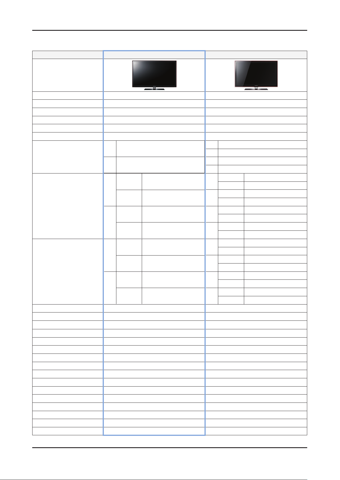
2-1-3. Specication Comparison to Old Models
Model
Design
UD5R (UA40D5500RJ) UC5R (UA**C5000QM)
O : application, X : non-application ※
Display Type
Built-in Tuner
Resolution
LCD Panel
Screen Size
Picture ratio
32" 80 W (Under 0.3 W Stand by)
Power Consumption
40" 100 W (Under 0.3 W Stand by)
with
32"
Dimensions (W x H x D)
40"
32"
Weight
40"
Brightness
Contrast Ratio
Picture Enhancer
Equalizer 5 Band 5 Band
Auto Volume Control
Surround Sound
Speaker Output
PIP O O
Double Window
Caption
Entertainment Mode
Game Mode
Energy Saving
NETWORK
Anynet+ O O
Antena
5,000(spec) / MEGA(3,000,000:1) (marketing) 5,000(spec) / 3,000,000:1 (marketing)
stand
without
stand
with
stand
without
stand
with
stand
without
stand
with
stand
without
stand
450(spec) / 400(marketing) cd/m
LED TV LED TV
O O
1920 X 1080 1920 X 1080
TFT LCD Panel 60 Hz TFT LCD Panel 60 Hz
32" / 40" 32" / 37" / 40" / 46"
16:9 16:9
32" 110 W (Under 0.3 W Stand by)
37" 120 W (Under 0.3 W Stand by)
40" 130 W (Under 0.3 W Stand by)
46" 130 W (Under 0.3 W Stand by)
with stand
30.2 x 9.4 x 20.9 (Inches)
30.2 x 1.2 x 18.4 (Inches)
37.6 x 10.0 x 25.1 (Inches)
37.6 x 1.2 x 22.6 (Inches)
9.96 (lbs)
7.22 (lbs)
14.36 (lbs)
11.08 (lbs)
2
HyperReal Engine (X5) HyperReal Engine (X4)
O O
Dolby Digital Plus Dolby Digital Plus / Pulse
10 W X 10 W 10 W X 10 W
X X
O O
X X
O O
O O
Internet TV DLNA
1(Cable/Air) 1(Cable/Air)
32"
without stand
with stand
37"
without stand
with stand
40"
without stand
with stand
46"
without stand
with stand
32"
without stand
with stand
37"
without stand
with stand
40"
without stand
with stand
46"
without stand
400(spec) / 400(marketing) cd/m
30.9 x 9.4 x 21.6 (Inches)
30.9 x 1.2 x 19.3 (Inches)
35.7 x 10.0 x 24.4 (Inches)
35.7 x 1.2 x 22.1 (Inches)
38.3 x 10.0 x 24.4 (Inches)
38.3 x 1.2 x 23.5 (Inches)
43.6 x 10.8 x 28.8 (Inches)
43.6 x 1.2 x 26.4 (Inches)
24.25 (lbs)
18.08 (lbs)
31.30 (lbs)
23.37 (lbs)
34.61 (lbs)
26.68 (lbs)
43.43 (lbs)
34.61 (lbs)
2
Page 11
2-5
2. Product specications
2-2. Detail Factory Option
If you replace the main board with new one, please change the factory option as well. ※
The options you must change are “Type”.
Model Name UN32D5500RF UN40D5500RF
Vendor
Panel
SMPS CODE BN44-00421B BN44-00423A
1 Factory Reset - -
2 Type 32A6AF0E 40A6AF0E
3 Local set US/SA_ATV US/SA_ATV
4 Model UD5500 UD5500
5 TUNER SI_ATC SI_ATC
6 Ch Table NONE NONE
7 Front Color U-T-R-BLK U-T-R-BLK
CODE
SPEC
AML
CMI
BN95-00436A
BN07-00989A
LTJ320HN01-V
LD320BGC-C1
BN95-00434A
LTJ400HM03-V
AML
Page 12
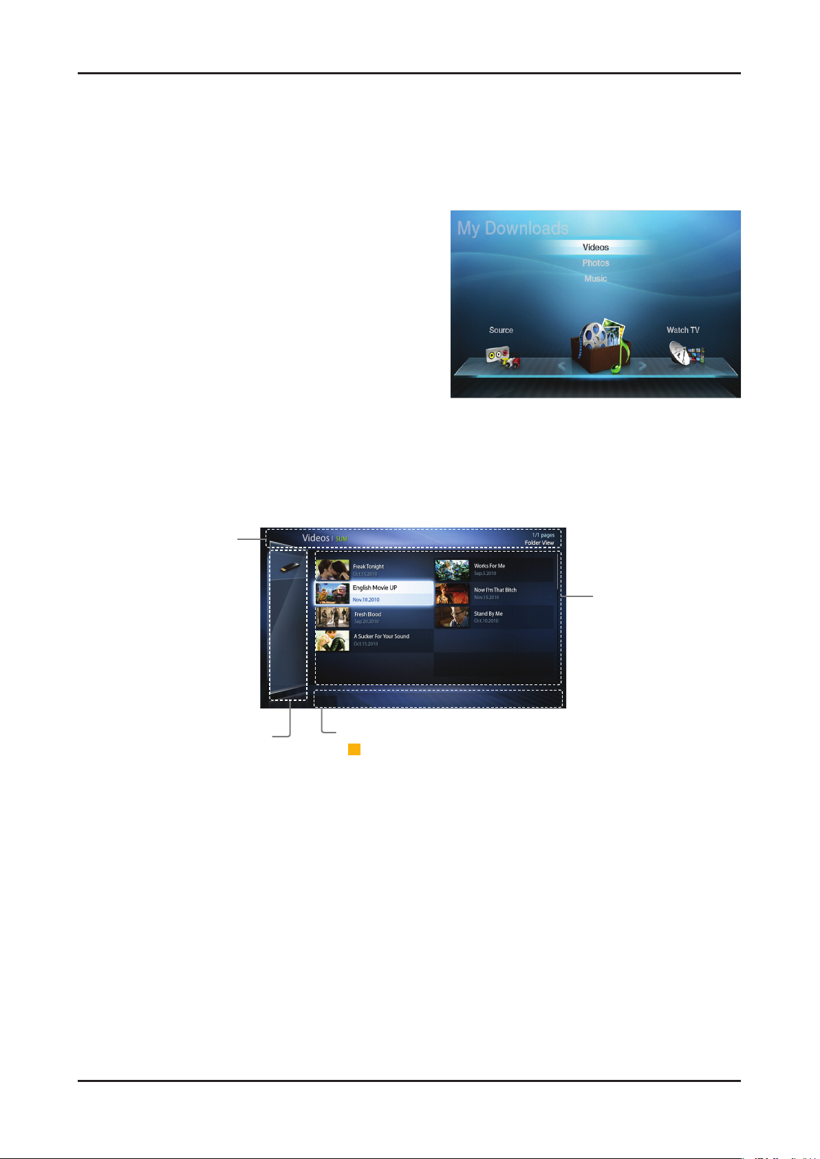
2-6
2. Product specications
Information:
You can ascertain the
selected device name,
contents mode, folder/
file name, page and
sorting list.
Contents mode / Device name:
You can select the desired
Contents mode or Device name.
When PC is connected, you can
select PC through PC Share
Manager.
Operation Buttons:
-
ACBD
Yellow (Edit Mode); Selects the desired music. The check box is
shown in the screen to check the music you want. It is only available in
Music.
- �
(Jump Page); Move to next or previous page.
- T Tools; Displays the option menu.
- R Return; Move to the previous step.
File List Section:
You can confirm the
files and groups that are
sorted by category.
T
Tools R Return
2-3. New Features explanation
2-3-1. My Contents
Using the My Contents
Enjoy photos, music and/or movie files saved on a USB Mass Storage Class (MSC) device and/or your PC.
Press the 1. CONTENT button to select My Contents.
2. u/d button to select desired menu (Videos, Photos,
Press
Music), then press the ENTERE button.
* It may differ depending on the model.
Screen Display
Move to the desired file using the ◄/►/▲/▼ buttons and then press the ENTERE or (Play) button.
The file is played. My Contents screen may differ depending on the way to enter the screen.
Page 13
2-7
2. Product specications
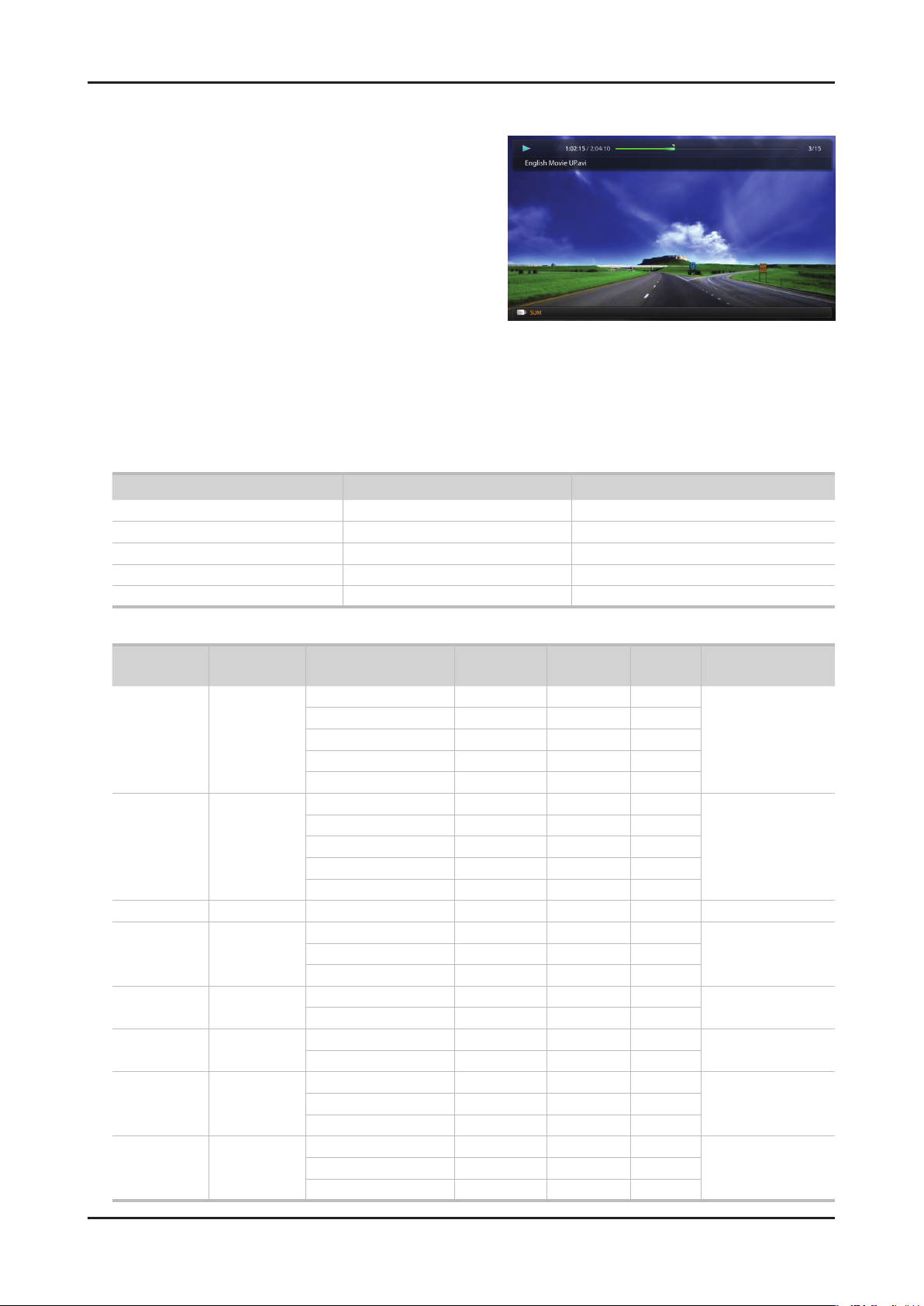
Videos
Playing Video01.
Press the 1. ◄/►/▲/▼ button to select the desired video in the le
list.
2. ENTERE button or (Play) button.
Press the
– The selected le name is displayed on the top with its playing
time.
– If video time information is unknown, play time and progress
bar are not displayed.
– During video playback, you can search using
button.
– You can use
playback.
N In this mode, you can enjoy movie clips contained on a Game, but you cannot play the Game itself.
(REW) and μ (FF) buttons during
● Supported Subtitle Formats
Name File extension Format
MPEG-4 time-based text .ttxt XML
SAMI .smi HTML
SubRip .srt string-based
SubViewer .sub string-based
Micro DVD .sub or .txt string-based
◄ and ►
● Supported Video Formats
File Extention Container Video Codec Resolution
Divx 3.11/4.x/5.1/6.0 1920 x 1080 6 ~ 30 8
*.avi
*.mkv
*.asf ASF
*.wmv ASF Window Media Video v9 1920 x 1080 6 ~ 30 25 WMA
*.mp4 MP4
*.3gp 3GPP
*.vro
*.mpg
*.mpeg
*.ts
*.tp
*.trp
AVI
MKV
VRO
VOB
PS
TS
XviD 1920 x 1080 6 ~ 30 8
H.264 BP/MP/HP 1920 x 1080 6 ~ 30 25
MPEG4 SP/ASP 1920 x 1080 6 ~ 30 8
Motion JPEG 640 x 480 6 ~ 30 8
Divx 3.11/4.x/5.1/6.0 1920 x 1080 6 ~ 30 8
XviD 1920 x 1080 6 ~ 30 8
H.264 BP/MP/HP 1920 x 1080 6 ~ 30 25
MPEG4 SP/ASP 1920 x 1080 6 ~ 30 8
Motion JPEG 640 x 480 6 ~ 30 8
H.264 BP/MP/HP 1920 x 1080 6 ~ 30 25
XVID 1920 x 1080 6 ~ 30 8
H.264 BP/MP/HP 1920 x 1080 6 ~ 30 25
MPEG4 SP/ASP 1920 x 1080 6 ~ 30 8
MPEG2 1920 x 1080 24/25/30 30
MPEG1 1920 x 1080 24/25/30 30
MPEG1 1920 x 1080 24/25/30 30
MPEG2 1920 x 1080 24/25/30 30
H.264 1920 x 1080 6 ~ 30 25
MPEG2 1920 x 1080 24/25/30 30
H.264 1920 x 1080 6 ~ 30 25
VC1 1920 x 1080 6 ~ 30 25
Frame rate
(fps)
Bit rate
(Mbps)
Audio Codec
MP3/AC3
/LPCM
/ADPCM
/DTS Core
MP3/AC3
/LPCM
/ADPCM
/WMA
MP3/ADPCM /AACMPEG4 SP/ASP 1920 x 1080 6 ~ 30 8
ADPCM/AAC
/HE-AAC
AC3/MPEG
/LPCM
AC3/MPEG
/LPCM/AAC
AC3/AAC
/MP3/DD+
/HE-AAC
Page 14

2-8
2. Product specications
Other Restrictions02.
N NOTE
If there are problems with the contents of a codec, the codec will not be supported.•
If the information for a Container is incorrect and the le is in error, the Container will not be able to play correctly.•
Sound or video may not work if the contents have a standard bit rate/frame rate above the compatible Frame/sec listed in the •
table above.
If the Index Table is in error, the Seek (Jump) function is not supported.•
When playing the video through network, it may not work depending on the network status.•
The videos over 10Mbps(bit rate) may be interrupted.•
Supports up to H.264, Level 4.1•
H.264 FMO / ASO / RS, VC1 SP / MP / AP L4 and •
AVCHD are not supported.
XVID, MPEG4 SP, ASP: •
– Below 1280 x 720: 60 frame max
– Above 1280 x 720: 30 frame max
GMC is not support.•
Video Decoder Audio Decoder
Supports up to WMA 7, 8, 9, STD, 9 PRO•
WMA Lossless, Voice Lossless, Voice is not supported.•
WMA sampling rate 22050Hz mono is not supported.•
Page 15
2-9
2. Product specications
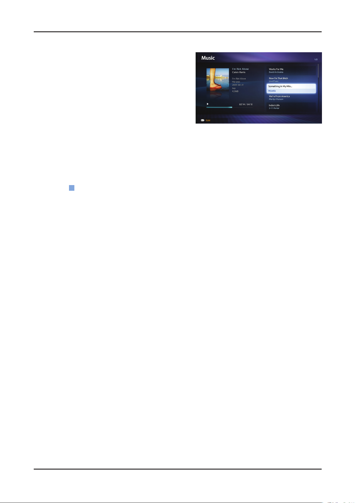
Music
Playing Music01.
Press the 1. ◄/►/▲/▼ button to select the desired Music in the
le list.
2. ENTERE button or (Play) button.
Press the
– You can use
playback.
N Only displays the les with MP3 and PCM le extension. Other le extensions are not displayed, even if they are saved on the
same USB device.
If the sound is abnormal when playing MP3 les, adjust the Equalizer in the Sound menu. (An over-modulated MP3 le may
N
cause a sound problem.)
Playing selected music
02.
(REW) and μ (FF) buttons during
Press the 1.
2.
Select the desired music.
– The check box appears to the left of the selected les.
3. TOOLS button and select Play Selected Contents.
Press the
– You can select or deselect all music pressing the
(Edit Mode) button.
C
Select All/Deselect All.
Page 16

2-10
2. Product specications
Photos
Viewing a Photo (or Slide Show)01.
Press the 1. ◄/►/▲/▼ button to select the desired Music in the
le list.
2. ENTERE button or (Play) button.
Press the
– When a selected photo is displayed, press the
button to start the slide show.
– During the slide show, all les in the le list will be displayed in
order.
N When you press the (Play) button in the le list, slide show will be started immediately.
Music les can be automatically played during the Slide Show if the Background Music is set to On.
N
The BGM Mode cannot be changed until the BGM has nished loading.
N
ENTERE
Page 17
2-11
2. Product specications
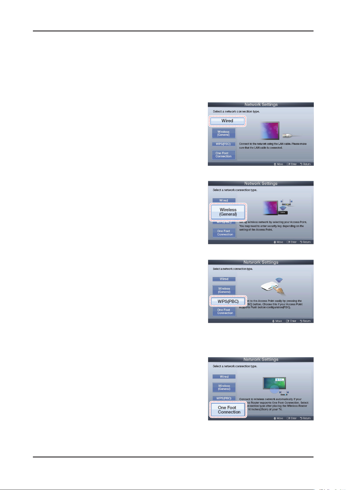
2-3-2. Setting the Network Connection
Connection Methods: You can setup the wireless network connection in four ways:
Auto Setup (Using the Auto Network Search function)•
Manual Setup•
WPS(PBC)•
One Foot Connection•
Network Settings
Wired Network Setup01.
1. Go to the Network Settings screen.
(MENUm
Select 2. Wired, and then press ENTERE.
The network connection screen appears and veries the network 3.
connection. When the connection has been veried, the "Internet
connected successfully." message appears.
Wireless (General) Network Setup02.
→
Network
→
Network Settings → ENTERE)
1. Go to the Network Settings screen.
(MENUm
Select 2. Wireless (General), and then press ENTERE.
The Network function searches for available wireless networks. 3.
When done, it displays a list of the available networks.
→
Network
→
Network Settings → ENTERE)
WPS(PBC) Network Setup03.
If your router has a PBC (WPS) button, follow these steps:
1. Go to the Network Settings screen.
(MENUm
Select 2. WPS(PBC), and then press ENTERE, then press
ENTERE again.
Press the WPS(PBC) button on your router within 2 minutes. Your 3.
TV automatically acquires all the network setting values it needs
and connects to your network.
The network connection screen appears, and network set up is done.
4.
→
Network
→
Network Settings → ENTERE)
One Foot Connection Network Setup04.
The One Foot connection make you easy to connect samsung TV and
samsung wireless router by placing samsung wireless router within
1foot(25cm) from samsung TV. If your wireless router does not support One
Foot Connection, you must connect using one of the other methods.
Turn on the power of wireless router and TV.1.
Go to the2. Network Settings screen.
→
(MENUm
Select 3. One Foot Connection,, and then press ENTERE, then
press ENTERE again.
The network connection screen appears, and network set up is done.4.
Network
→
Network Settings → ENTERE)
Page 18
2-12
2. Product specications
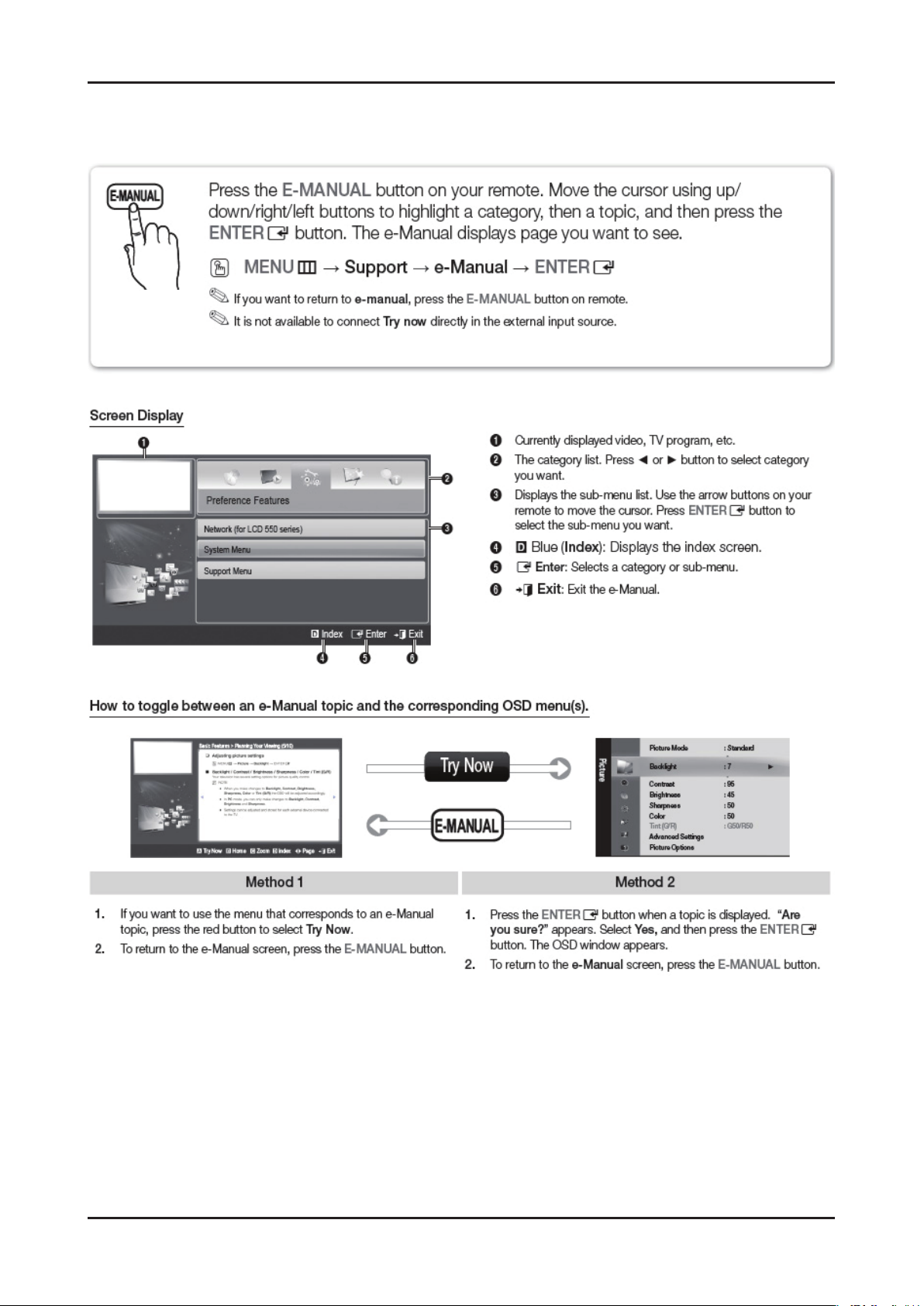
2-3-3. e-Manual
How to view the e-Manual
Page 19
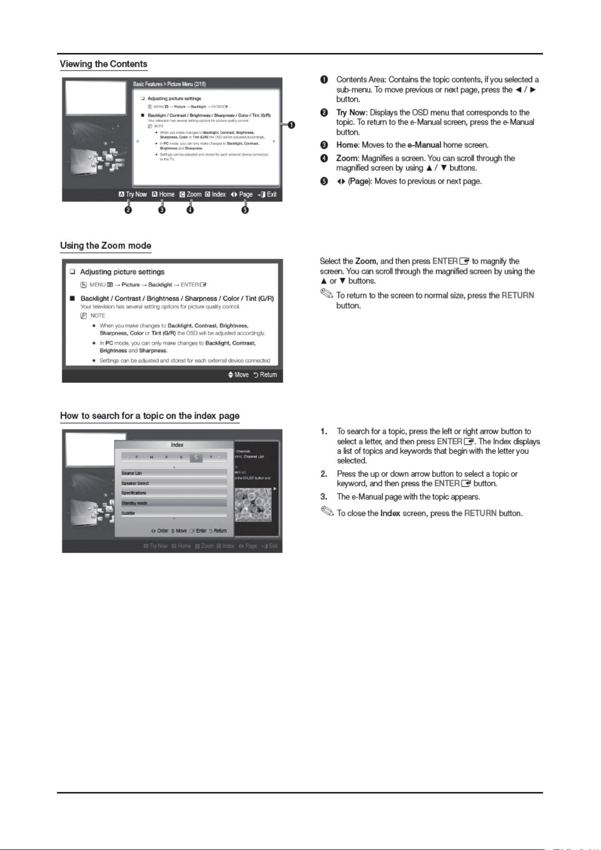
2-13
2. Product specications
Page 20
2-14
2. Product specications
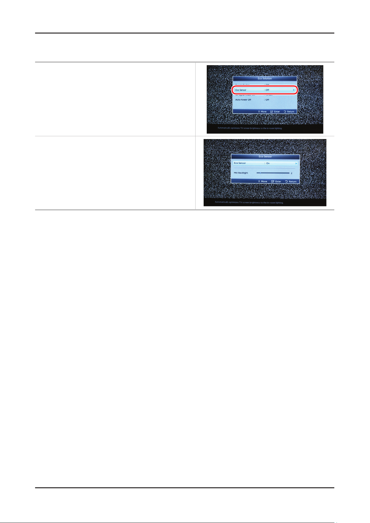
2-3-5. Eco sensor
* To enhance your power savings; the
Menu System Eco solution Eco Sensor
Min Backlight: When ECO sensor is On, the minimum screen
brightness can be adjusted manually.
Page 21
2-15
2. Product specications
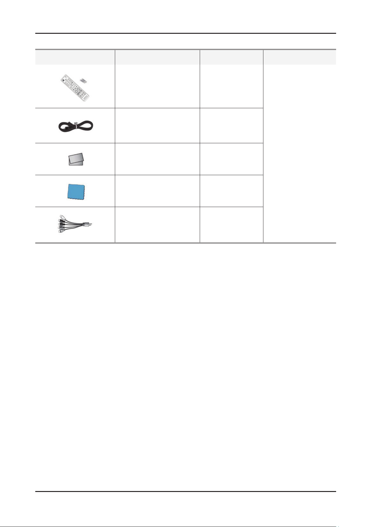
2-4. Accessories
Product Description Code. No Remark
Remote Control & Batteries
(AAA x 2)
Power Cord 3903-000598
Warranty Card /
Safety Guide Manual
Cleaning Cloth
Component Adapter BN39-01154W
AA59-00443A
BP68-00263E
AA68-03242L
BN63-01798B
Supplied
Accessories
Page 22
3. Disassembly and Reassembly
3. Disassembly and Reassembly
This section of the service manual describes the disassembly and reassembly procedures for the LED TV.
WARNING: This LED TV contains electrostatically sensitive devices. Use caution when handling these components.
3-1. Disassembly and Reassembly
Cautions: 1. Disconnect the LED TV from the power source before disassembly.
2. Follow these directions carefully; never use metal instruments to pry apart the cabinet.
Description Picture Description Screws
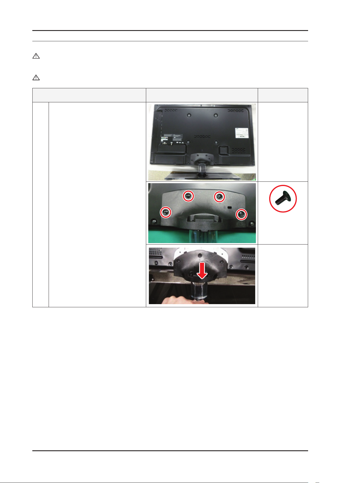
Place TV face down on cushioned table.
1
- Remove 4 screws from the stand.
- Remove stand.
6001-002621
(M4xL8, MACHINE)
3-1
Page 23
3-2
3. Disassembly and Reassembly
Description Picture Description Screws
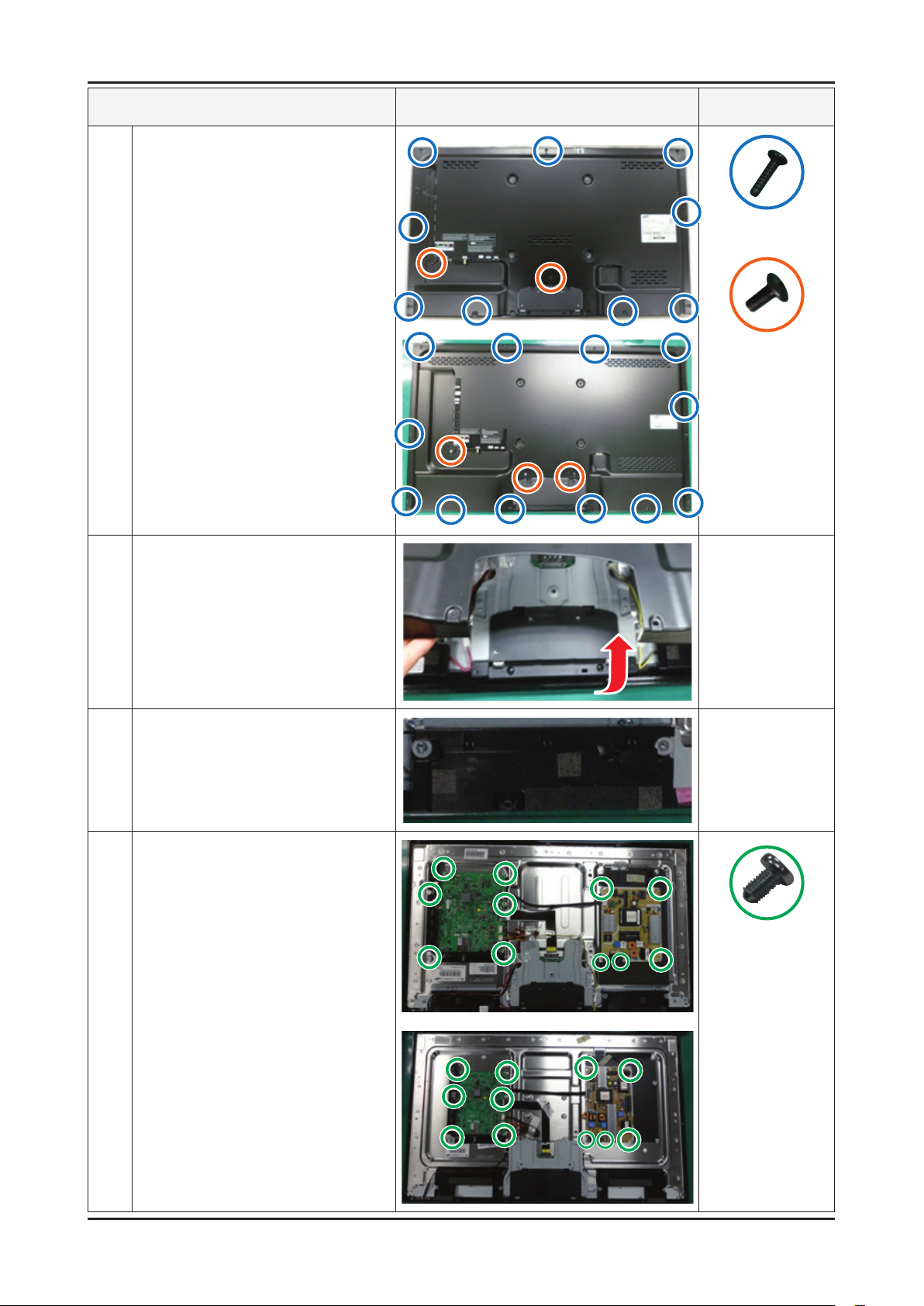
Remove the screws of Rear-cover.
2
- 32" : 13 EA
- 40" : 14 EA
6003-001782
(M4 x L12, TAPETYPE)
6001-002671
(M3 x L6, MACHINE)
Lift up the Rear-cover.
3
Remove the Left and Right Speaker.
4
Remove the 6 screws of Main Board
5
and 5 screws of IP Board.
6001-002653
(M3 x L6, MACHINE)
Page 24
3-3
3. Disassembly and Reassembly
Description Picture Description Screws
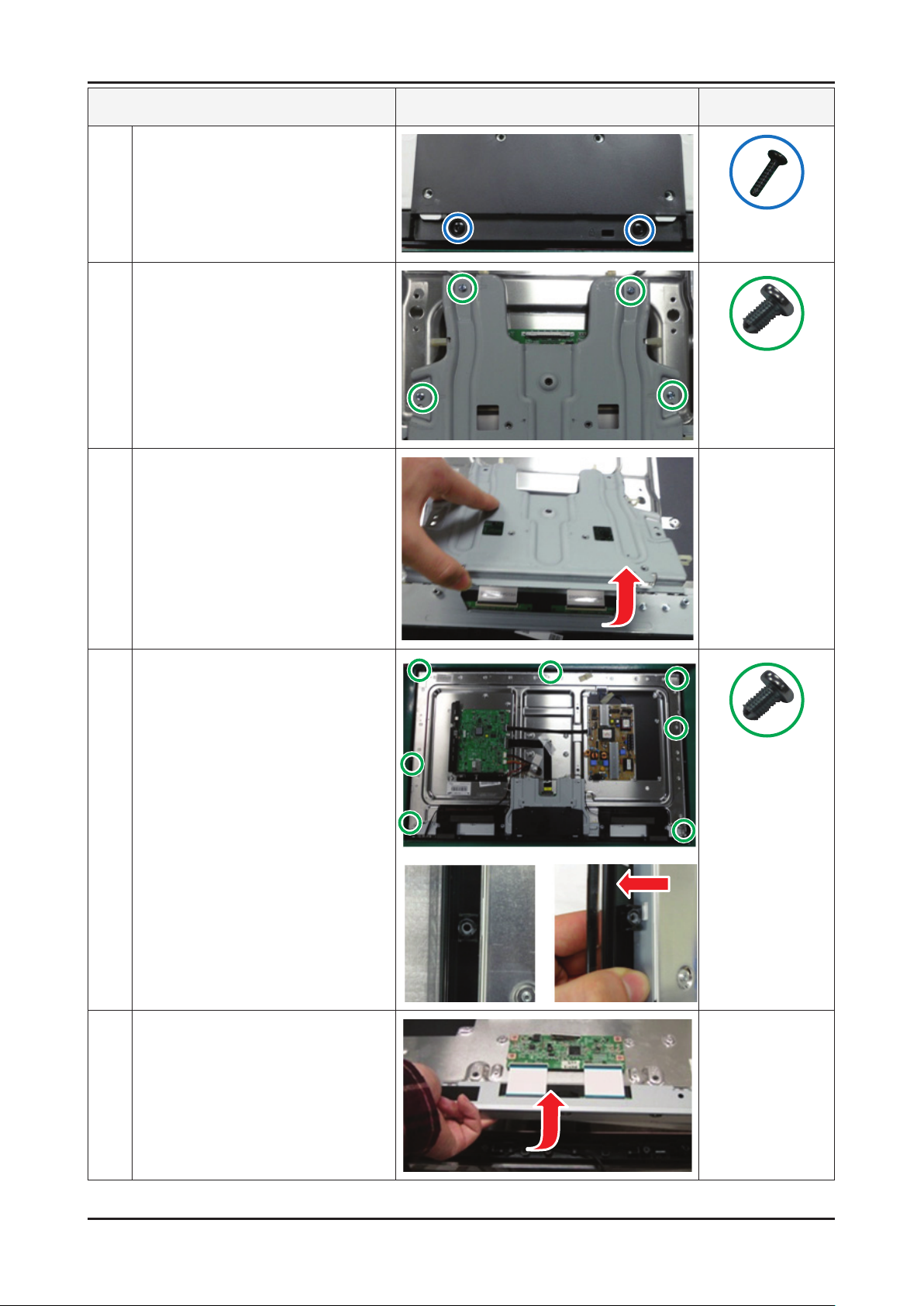
Remove the 2 screws of Stand Link
6
Cover.
Remove the 4 screws of Stand Link.
7
Lift up the Stand Link.
8
6003-001782
(M4 x L12, TAPETYPE)
6001-002653
(M3 x L6, MACHINE)
Detach the Pront Hook.
9
Lift up the Panel.
10
6001-002653
(M3 x L6, MACHINE)
Reassembly procedures are in the reverse order of disassembly procedures. ※
Page 25
3-4
3. Disassembly and Reassembly
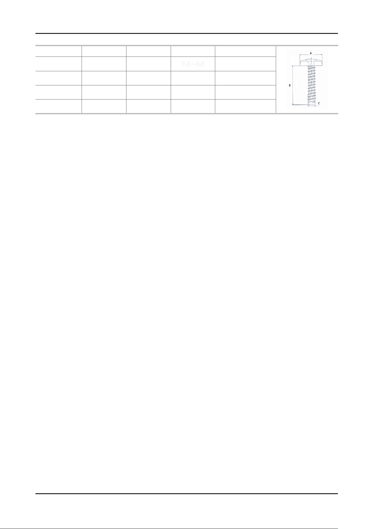
Screw Size
Code No. A (mm) B (mm) C (mm) Q'ty
6001-002621 7.8 ~ 8.3 7.4 ~ 8.0 7.4 ~ 8.0 4EA
6003-001782 7.8 ~ 8.2 11.4 ~ 12.0 3.8 ~ 3.9 14 EA
6001-002671 7.1 ~ 7.5 5.7 ~ 6.0 2.98 ~ 3.02 4 EA
6003-001782 7.8 ~ 8.2 11.4 ~ 12.0 3.8 ~ 3.9 2EA
Page 26
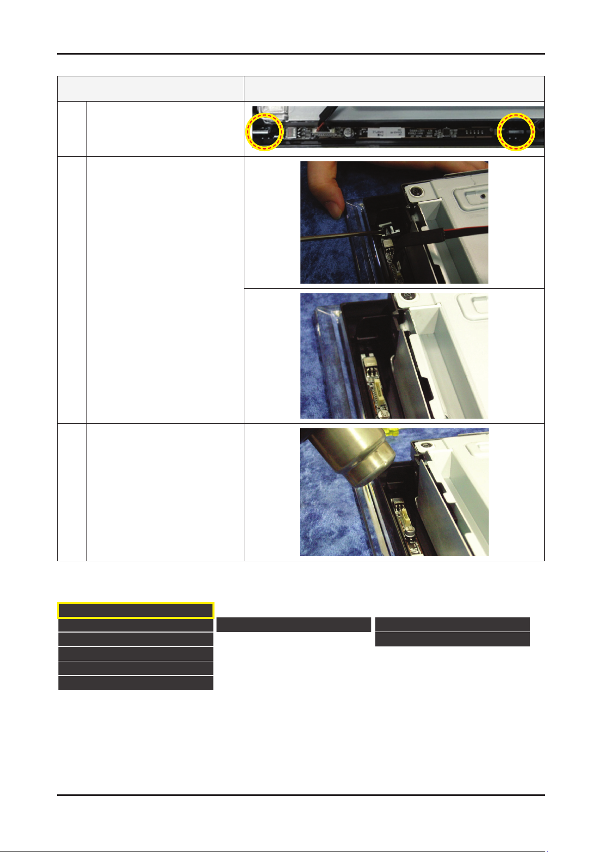
3-5
3. Disassembly and Reassembly
How to disassembly Function & IR ASSY
Description Picture Description
Check the 2 Function Clips.
1
Remove the 2 Function Clips.
2
Heat the Function Assy by Heat Gun
3
and Lift up the Function Assy.
Touch Function Key
Control the sensitivity of function key is available in Factory mode
Option
Control
SVC
Expert
ADC/WB
Advanced
KEY SENSITIVITY
Default : 36
1~254 and Not Used•
Raising this value, the sensitivity decreases•
Not Used : Not use sensitivity, use Function default value•
Sub Option KEY SENSITIVITY
FUNCTION KEY
Page 27

4. Troubleshooting
4-1. Troubleshooting
4-1-1. Previous check
Check the various cable connections rst. 1.
• Check to see if there is a burnt or damaged cable.
• Check to see if there is a disconnected or loose cable connection.
• Check to see if the cables are connected according to the connection diagram.
Check the power input to the Main Board.2.
4. Troubleshooting
4-1
Page 28
4-2
4. Troubleshooting
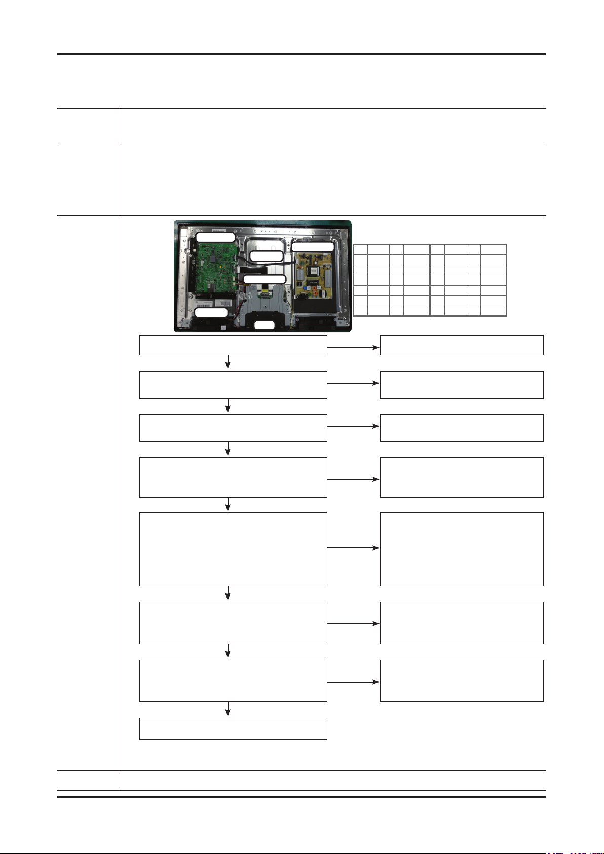
4-1-2. How to check fault symptom
No Power
The LEDs on the front panel do not work when connecting the power cord. -
Symptom
Major
checkpoints
The SMPS relay does not work when connecting the power cord. The units appears to be dead. -
The IP relay or the LEDs on the front panel does not work when connecting the power cord if the cables are
improperly connected or the Main Board or SMPS is not functioning.
In this case, check the following:
Check the internal cable connection status inside the unit. Check the fuses of each part. Check the output voltage of SMPS. Replace the Main Board. -
Diagnostics
Main Ass’y
14p cable
LVDS cable
Speaker
-
T-con
Power Ass’y
Yes
Check the backlight on,
when 14p cable unconnected ?
Yes
Check ‘Stand-By 5V’ DCA5V
appear at BD207?
Yes
Check Power input of Main Ass’y ?
DC B13V, B5V appear at BD209(B13V),
BD213/208(B5V)?
Yes
Check Power input of submicom IC(A3.3V) ?
Check Power of nand ash IC(B3.3V)
Check Power of main IC(B2.5V, B1.1V)
Check Power of DDR IC(B1.5V) appear at
IC202(#5) L201 (B3.3V) BD1008/9/10/11
(B2.5V) BD1002/3/4 (B1.1V) BD1012 (B1.5V)
Yes
Main Assy
1 B5V 2 SW_PW
3 B5V 4 A5V
5 GND 6 GND
7 B12VS 8 GND
9 B12VS 10 SW_INV
11 B13V 12 NC
13 B13V 14 DMM
No
No
Change 14p power cable and SMPS.
No
Change 14p power cable and SMPS.
No
Change 14p power cable and SMPS.
No
Power Assy
1 B5V 2 SW_PW
3 B5V 4 A5V
5 GND 6 GND
7 B12VS 8 GND
9 B12VS 10 SW_INV
11 B13V 12 NC
13 B13V 14 DMM
Check an AC power connection.Power indicator LED on?
Change the Main Assy.
Check Power of LVDS (13V) appear at
No
LVDS connector Pin #1~5 of T-con b’d?
Yes
Does proper DC B13V
No
appear at F1 of T-con b’d?
Yes
Please, Contact tech support.
Caution Make sure to disconnect the power before working on the IP board.
Change the LVDS cable.
Change the T-con b’d.
Page 29
4-3
4. Troubleshooting
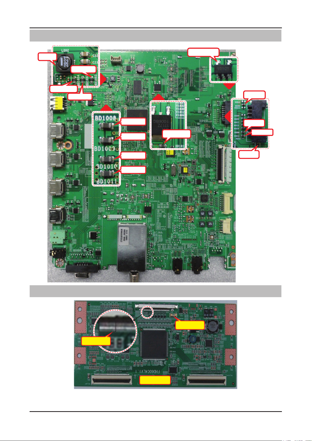
Location (Main) - TOP
L201
BD1004
BD1002
BD1003
BD1008
BD1009
BD1010
BD1011
BD1012
IC202(#5)
BD209
BD208
BD213
BD207
Pin #1~5
Location (T-CON) - TOP
F1
40" TCON
Page 30
4-4
4. Troubleshooting
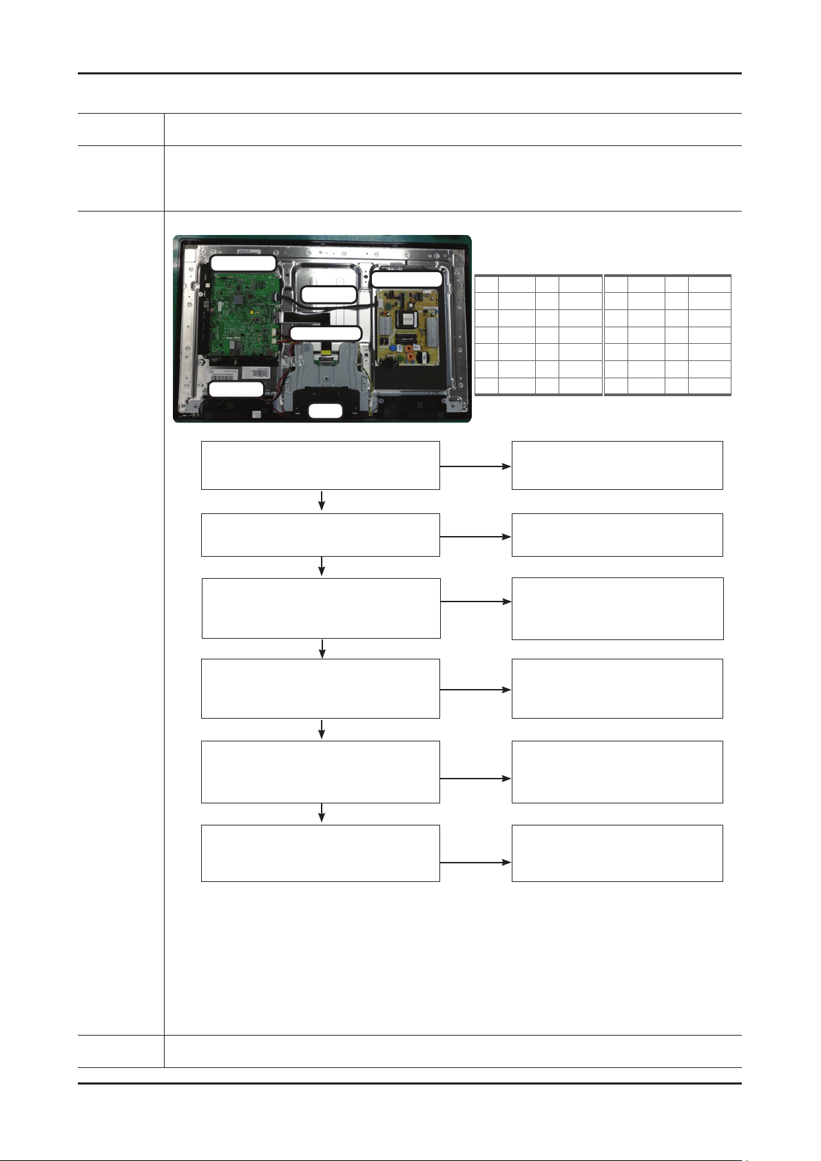
No Video_Analog PC signal
Symptom Audio is normal but no picture is displayed on the screen. -
Major
checkpoints
Check the PC source Check the Arsenal, Check the Chelsea. This may happen when the LVDS cable connecting the Main Board and the Panel is disconnected. -
Main Ass’y
14p cable
LVDS cable
Speaker
T-con
Power indicator LED is off.
Lamp(Backlight) on, no video ?
Yes
Check the PC source and
check the connection of D-SUB ?
Yes
Power Ass’y
Main Assy
1 B5V 2 SW_PW
3 B5V 4 A5V
5 GND 6 GND
7 B12VS 8 GND
9 B12VS 10 SW_INV
11 B13V 12 NC
13 B13V 14 DMM
No
No
Check a set in the ‘Stand-by mode’
Check external devices and
Power Assy
1 B5V 2 SW_PW
3 B5V 4 A5V
5 GND 6 GND
7 B12VS 8 GND
9 B12VS 10 SW_INV
11 B13V 12 NC
13 B13V 14 DMM
or ‘DPMS mode’.
connections.
Diagnostics
check the Self Diagnosis
(SupportSelf DiagnosisPicture Test)
Dose the promblem still exist self diagnosis ?
Yes
Does the signal appear at
R804(R), R805(G), R806(B)
BD404(H), BD405(V) ?
Yes
Does the digital data appear at
TP-EVEN_TXCLK+, EVEN_TXCLK- ,
ODD_TXCLK+, ODD_TXCLK- ?
Yes
Check the LVDS cable ?
Check the T-Con B’d ?
Replace the LCD panel ?
No
No
No
No
Input the analog PC signal properly.
Check CN401, PC cable.
Change the Main Assy
Check IC1001 (X5)
Change the Main Assy.
Please, Contact Tech support.
Caution Make sure to disconnect the power before working on the IP board.
Page 31
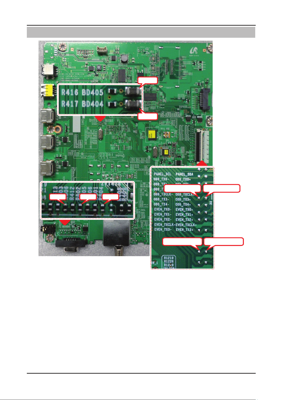
4-5
4. Troubleshooting
Location (Main) - TOP
BD405
BD404
R806 R805 R804
ODD_TXCLK-
EVEN_TXCLK-
ODD_TXCLK+
EVEN_TXCLK+
Page 32
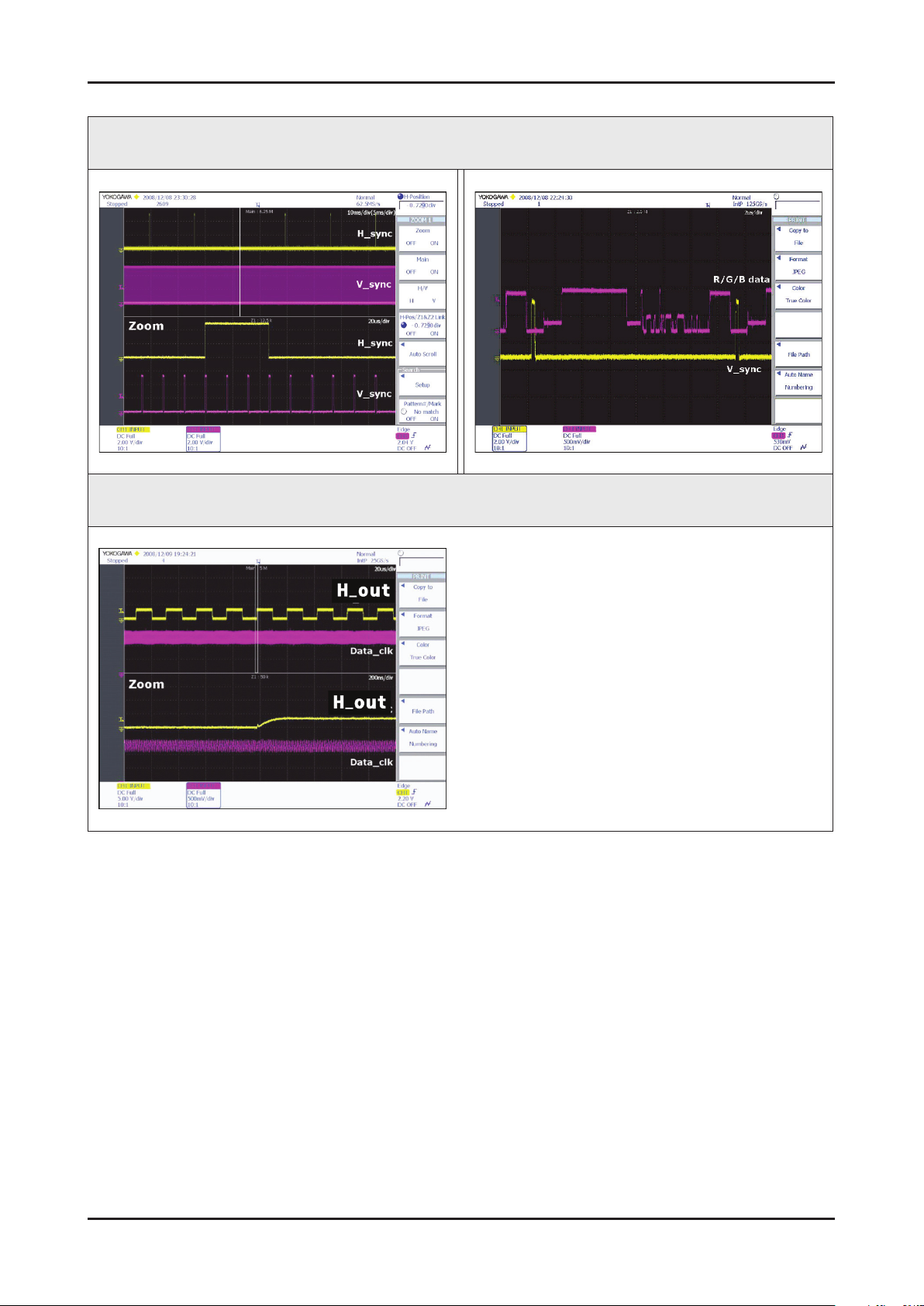
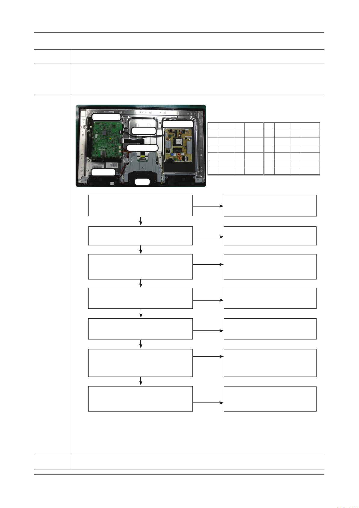
4-6
4. Troubleshooting
WAVEFORMS
1 PC input (V-sink, H-sink, R/G/B)
2 LVDS output
Page 33
4-7
4. Troubleshooting
No video_HDMI1, 2, 3, 4 - Digital signal
Symptom Audio is normal but no picture is displayed on the screen. -
Major
checkpoints
Check the HDMI source. -
Check the HDMI switch, Check the Chelsea. -
This may happen when the LVDS cable connecting the Main Board and the Panel is disconnected. -
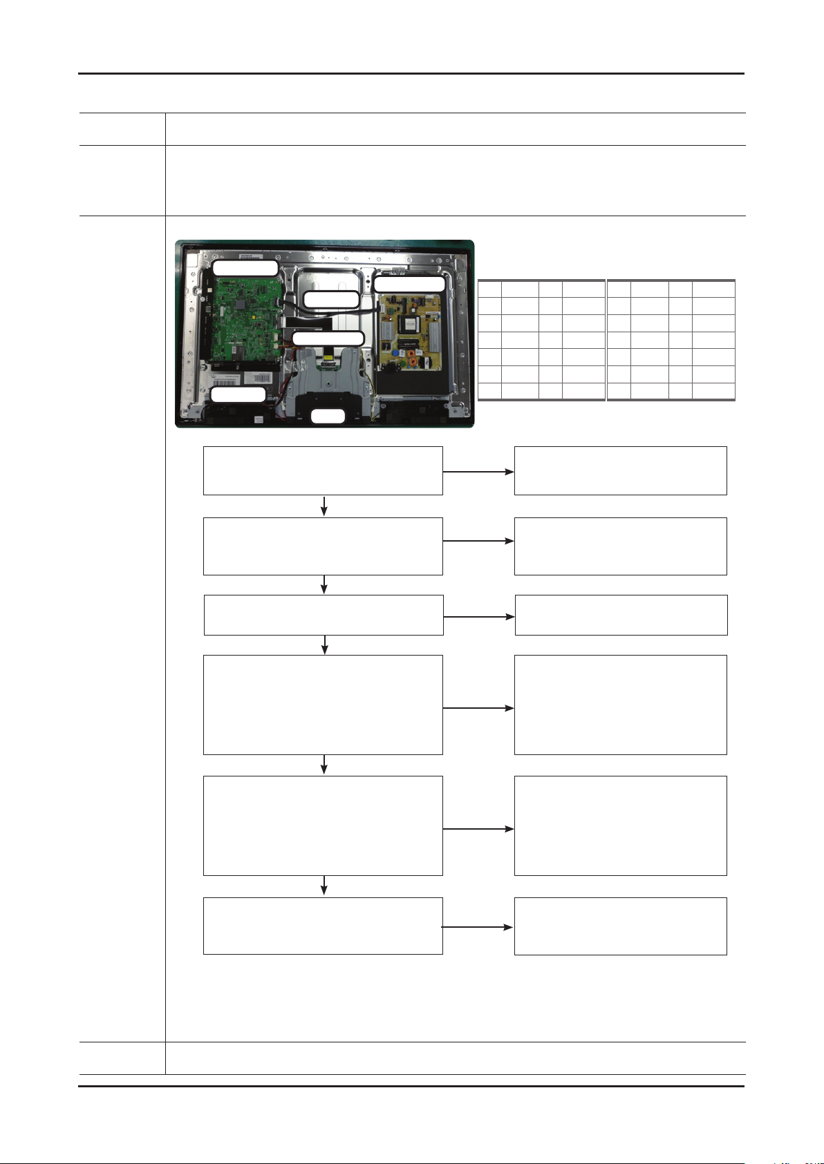
Main Ass’y
Power Ass’y
14p cable
LVDS cable
Speaker
T-con
Power indicator LED is off.
Lamp(Backlight) on, no video ?
Yes
check the Self Diagnosis
(SupportSelf DiagnosisPicture Test)
Dose the promblem still exist self diagnosis ?
Yes
Main Assy
1 B5V 2 SW_PW
3 B5V 4 A5V
5 GND 6 GND
7 B12VS 8 GND
9 B12VS 10 SW_INV
11 B13V 12 NC
13 B13V 14 DMM
No
No
Check a set in the 'Stand-by mode'.
Check external devices and
Power Assy
1 B5V 2 SW_PW
3 B5V 4 A5V
5 GND 6 GND
7 B12VS 8 GND
9 B12VS 10 SW_INV
11 B13V 12 NC
13 B13V 14 DMM
connections.
Diagnostics
Check the HDMI source and
check the connection of HDMI cable ?
Yes
Does the signal appear at
CN1002 (Pin#12 , #7 )(HDMI1)
CN1003 (Pin#12 , #7 )(HDMI2)
CN1004 (Pin#12 , #7 )(HDMI3)
CN1001 (Pin#12 , #7 )(HDMI4)
(HDMI RX_Clk , RX_Data) ?
Yes
Does the digital data appear at
TP-E_TXCLK+, E_TXCLK- ,
O_TXCLK+, O_TXCLK-?
Yes
Check the LVDS cable ?
Check the T-Con B’d ?
Replace the LCD panel ?
No
No
No
No
Input the HDMI signal properly.
Check
CN601,CN602,CN603,CN604
Check HDMI cable
Change the Main Assy
.
Check IC1001 (X5)
Change the Main Assy.
Please, Contact Tech support.
Caution Make sure to disconnect the power before working on the IP board.
Page 34
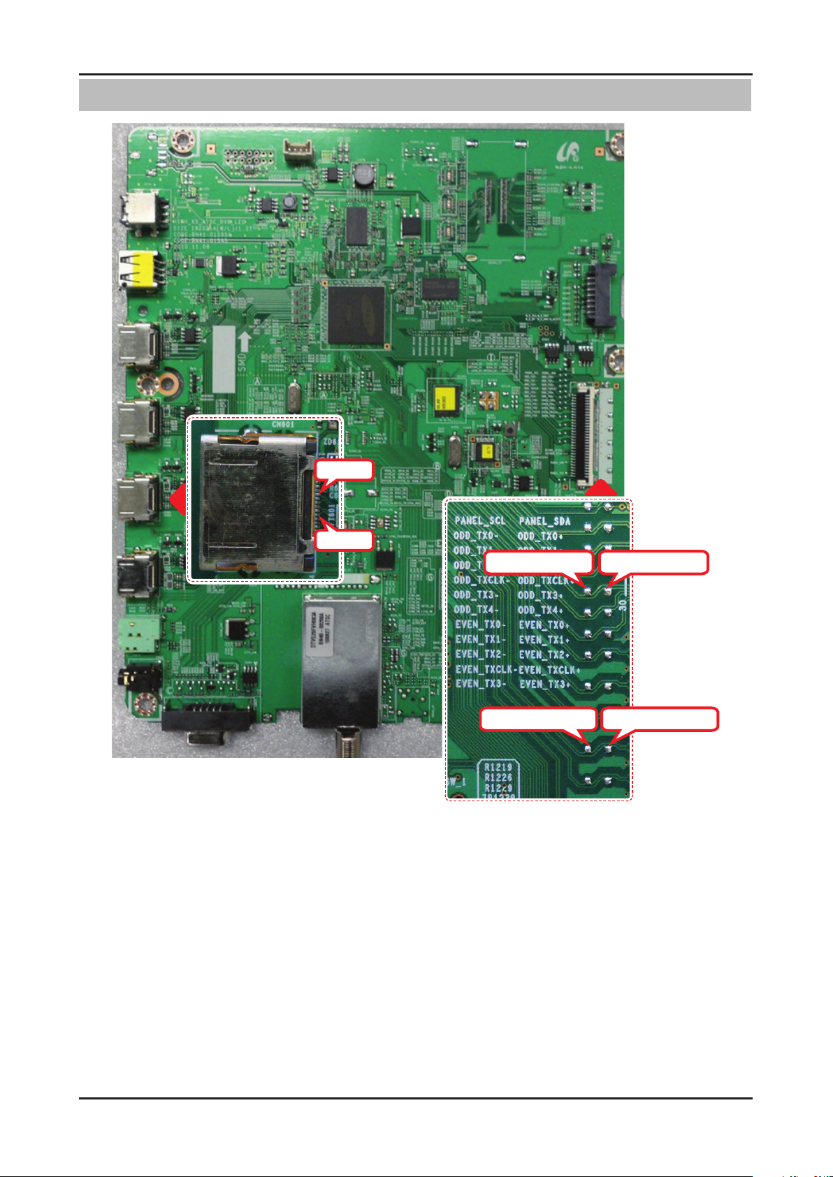
4-8
4. Troubleshooting
Location (Main) - TOP
Pin #12
Pin #7
ODD_TXCLK-
EVEN_TXCLK-
ODD_TXCLK+
EVEN_TXCLK+
Page 35
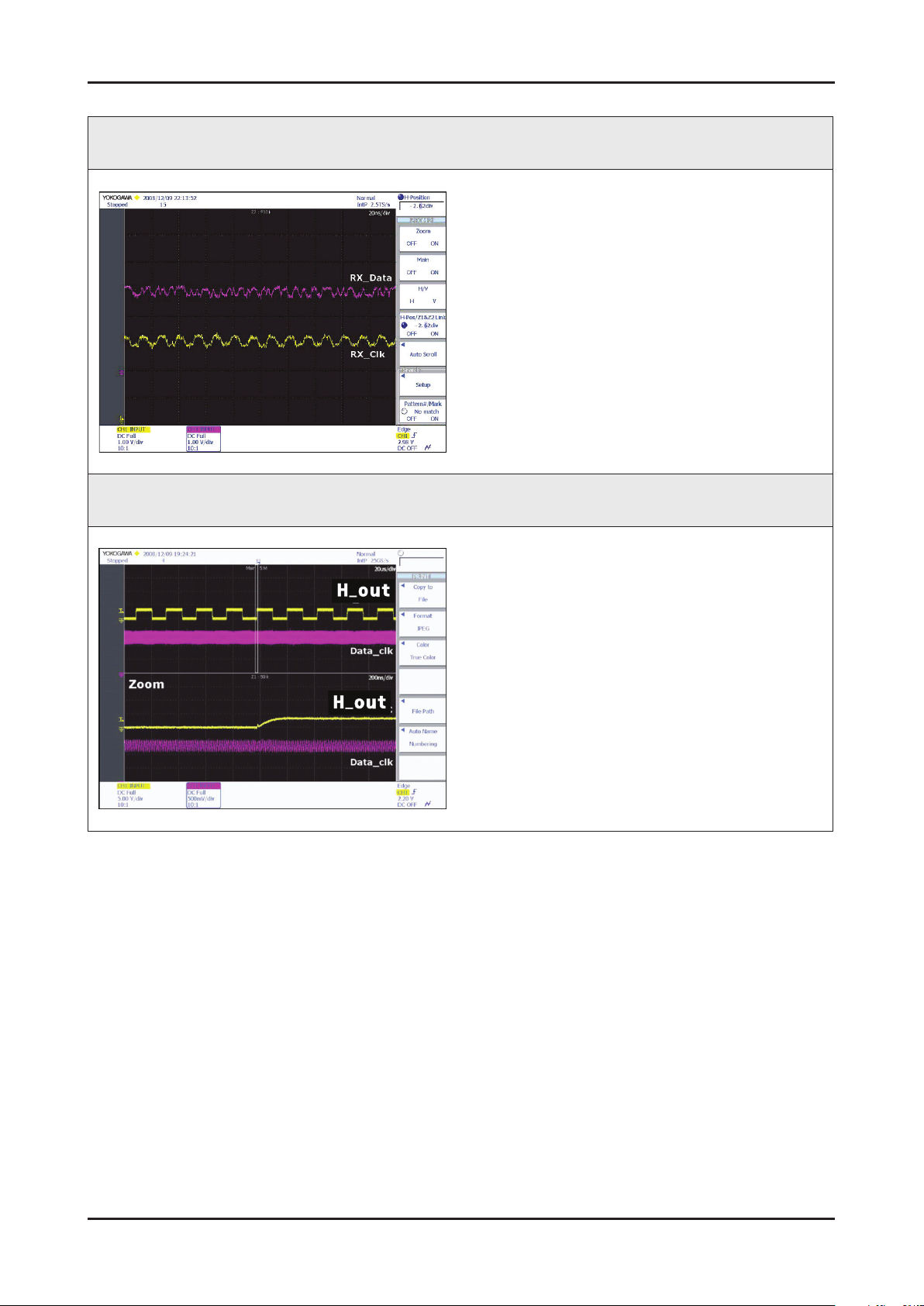
4-9
4. Troubleshooting
WAVEFORMS
3 PC input (V-sink, H-sink, R/G/B)
2 LVDS output
Page 36
4-10
4. Troubleshooting
No Video_Tuner - CVBS
Symptom Audio is normal but no picture is displayed on the screen. -
Major
checkpoints
Check the Tuner CVBS source. -
Check the Tuner, Check the Chelsea. -
This may happen when the LVDS cable connecting the Main Board and the Panel is disconnected. -
Main Ass’y
14p cable
LVDS cable
Speaker
T-con
Power indicator LED is off.
Lamp(Backlight) on, no video ?
Yes
Check the RF source and
check the connection of RF cable ?
Yes
Power Ass’y
Main Assy
1 B5V 2 SW_PW
3 B5V 4 A5V
5 GND 6 GND
7 B12VS 8 GND
9 B12VS 10 SW_INV
11 B13V 12 NC
13 B13V 14 DMM
No
No
Check a set in the 'Stand-by mode'
Input the RF source properly.
Power Assy
1 B5V 2 SW_PW
3 B5V 4 A5V
5 GND 6 GND
7 B12VS 8 GND
9 B12VS 10 SW_INV
11 B13V 12 NC
13 B13V 14 DMM
Diagnostics
check the Self Diagnosis
(SupportSelf DiagnosisPicture Test)
Dose the promblem still exist self diagnosis ?
Yes
Does the DC B1.8V B3.3V
appear at #3, #5 Pin of Tuner ?
Yes
Check the CVBS data
at #15 Pin of Tuner ?
Yes
Does the digital data appear at
TP-E_TXCLK+, E_TXCLK- ,
O_TXCLK+, O_TXCLK- ?
Yes
Check the LVDS cable ?
Check the T-Con B’d ?
Replace the LCD panel ?
No
No
No
No
No
Check external devices and
connections.
Change the Main Assy.
Change the Main Assy.
Check IC1001 (X5)
Change the Main Assy.
Please, Contact Tech support.
Caution Make sure to disconnect the power before working on the IP board.
Page 37
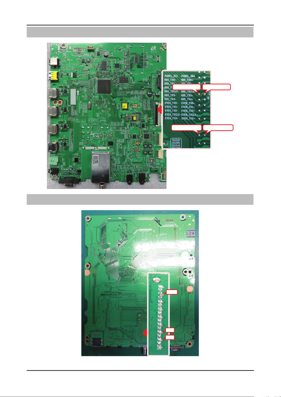
4-11
4. Troubleshooting
Location (Main) - TOP
Location (Main) - BOTTOM
ODD_TXCLK-
EVEN_TXCLK-
ODD_TXCLK+
EVEN_TXCLK+
#15
#5
#3
Page 38
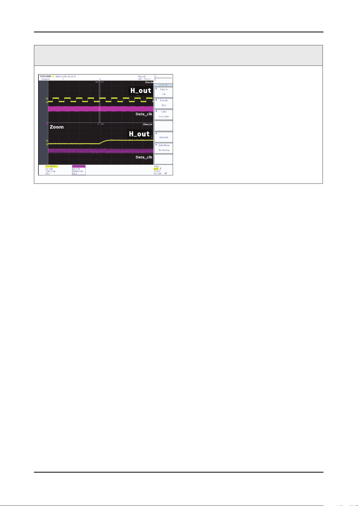
4-12
4. Troubleshooting
WAVEFORMS
2 LVDS output
Page 39
4-13
4. Troubleshooting
No Video_Tuner DTV
Symptom Audio is normal but no picture is displayed on the screen. -
Major
checkpoints
Check the DTV source. -
Check the Tuner, Check the Chelsea. -
This may happen when the LVDS cable connecting the Main Board and the Panel is disconnected. -
Main Ass’y
14p cable
LVDS cable
Speaker
T-con
Power indicator LED is off.
Lamp(Backlight) on, no video ?
Yes
Check the connection of RF cable ?
Power Ass’y
Main Assy
1 B5V 2 SW_PW
3 B5V 4 A5V
5 GND 6 GND
7 B12VS 8 GND
9 B12VS 10 SW_INV
11 B13V 12 NC
13 B13V 14 DMM
No
No
Check a set in the 'Stand-by mode'
Input the RF source properly.
Power Assy
1 B5V 2 SW_PW
3 B5V 4 A5V
5 GND 6 GND
7 B12VS 8 GND
9 B12VS 10 SW_INV
11 B13V 12 NC
13 B13V 14 DMM
Diagnostics
Yes
check the Self Diagnosis
(SupportSelf DiagnosisPicture Test)
Dose the promblem still exist self diagnosis ?
Yes
Check the 'signal strength' in Self Diagnosis
menu Strength is enough ?
Yes
Does the DC B1.8V B3.3V
appear at #3, #5 Pin of Tuner ?
Yes
Check the DTV data(DIF+, DIF-)
appear at #11, #10 Pin of Tuner ?
Yes
Does the digital data appear at
TP-E_TXCLK+, E_TXCLK- ,
O_TXCLK+, O_TXCLK- ?
Yes
Check the LVDS cable ?
Check the T-Con B'd ?
Replace the LCD panel ?
No
No
No
No
No
No
Check external devices and
connections.
Check the D-TV source.
Change the Main Assy.
Change the Main Assy.
Check IC1001 (X5)
Change the Main Assy.
Please, Contact Tech support.
Caution Make sure to disconnect the power before working on the IP board.
Page 40
4-14
4. Troubleshooting
Location (Main) - TOP
Location (Main) - BOTTOM
ODD_TXCLK-
EVEN_TXCLK-
ODD_TXCLK+
EVEN_TXCLK+
#12
#11
#5
#3
Page 41
4-15
4. Troubleshooting
WAVEFORMS
2 LVDS output
Page 42
4-16
4. Troubleshooting
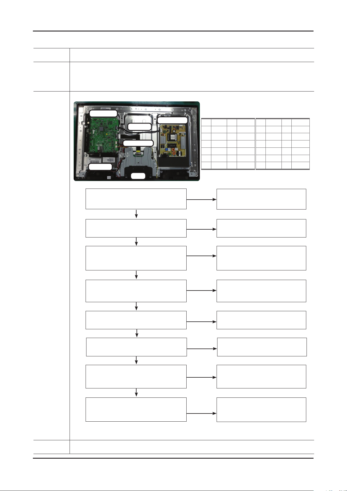
No Video_Video CVBS
Symptom Audio is normal but no picture is displayed on the screen. -
Major
checkpoints
Check the Video CVBS source -
Check the Chelsea. -
This may happen when the LVDS cable connecting the Main Board and the Panel is disconnected. -
Main Ass’y
14p cable
LVDS cable
Speaker
T-con
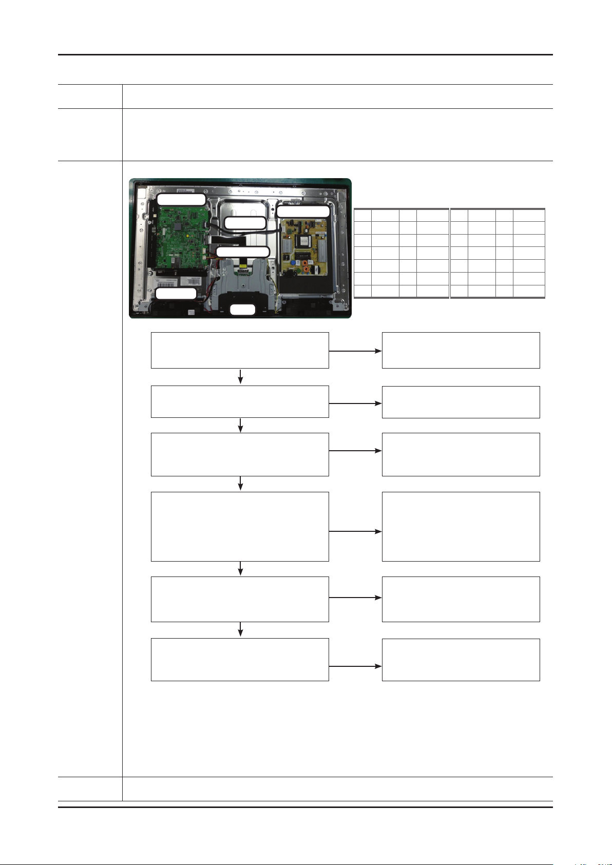
Power indicator LED is off.
Lamp(Backlight) on, no video ?
Yes
Check the video source and
check the connection of video cable?
Yes
Power Ass’y
Main Assy
1 B5V 2 SW_PW
3 B5V 4 A5V
5 GND 6 GND
7 B12VS 8 GND
9 B12VS 10 SW_INV
11 B13V 12 NC
13 B13V 14 DMM
No
No
Check a set in the 'Stand-by mode'
Input the video source properly.
Power Assy
1 B5V 2 SW_PW
3 B5V 4 A5V
5 GND 6 GND
7 B12VS 8 GND
9 B12VS 10 SW_INV
11 B13V 12 NC
13 B13V 14 DMM
Diagnostics
check the Self Diagnosis
(SupportSelf DiagnosisPicture Test)
Dose the promblem still exist self diagnosis ?
Yes
Does the CVBS data appear at
R816/R821(CVBS1) ?
Yes
Does the digital data appear at
TP-E_TXCLK+, E_TXCLK- ,
O_TXCLK+, O_TXCLK- ?
Yes
Check the LVDS cable ?
Check the T-Con B'd ?
Replace the LCD panel ?
No
No
No
No
Check external devices and
connections.
Check CN504
Change the Main Assy.
Check IC1001 (X5)
Change the Main Assy.
Please, Contact Tech support.
Caution Make sure to disconnect the power before working on the IP board.
Page 43
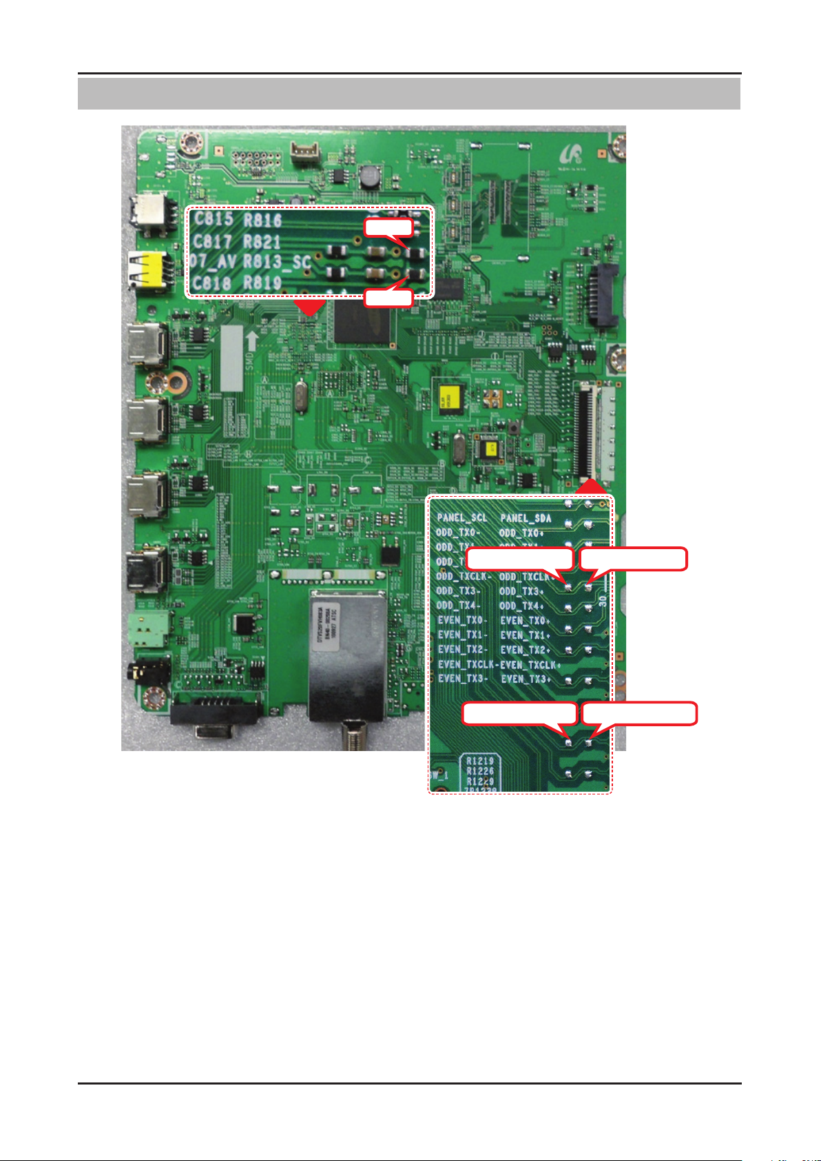
4-17
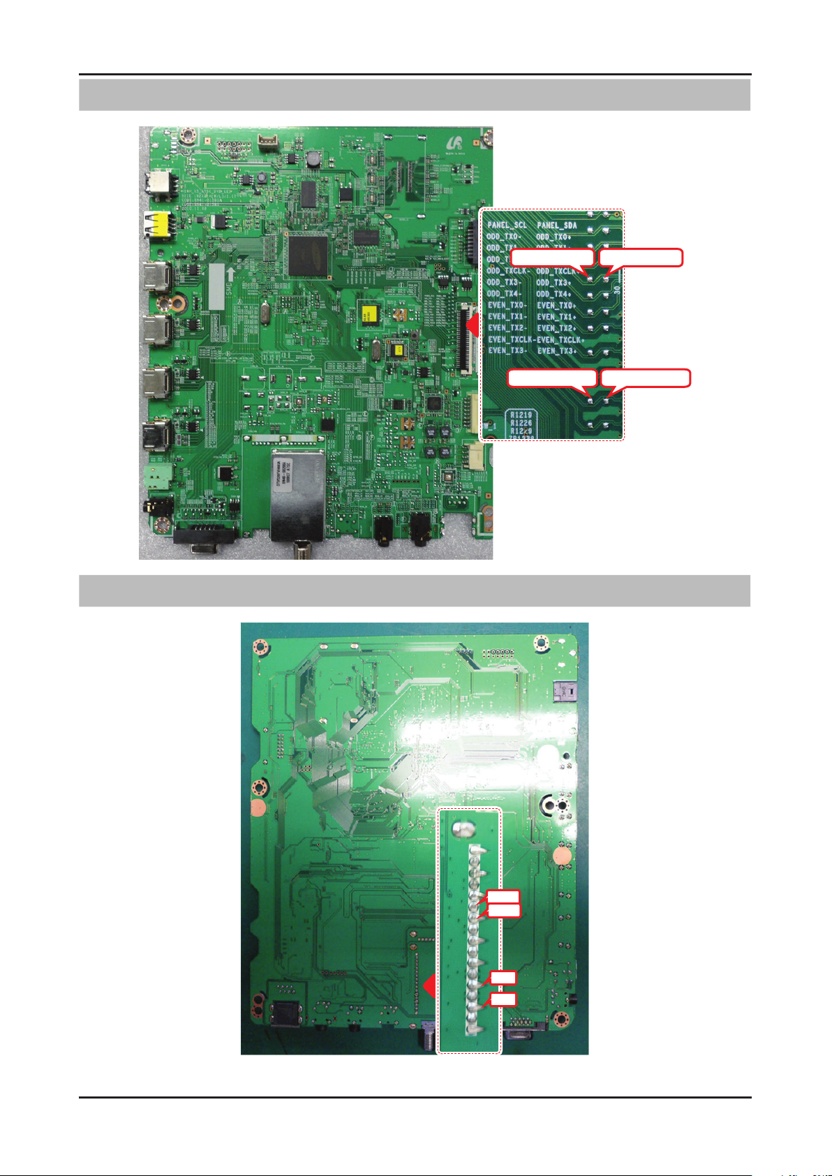
4. Troubleshooting
Location (Main) - TOP
R816
R821
ODD_TXCLK-
EVEN_TXCLK-
ODD_TXCLK+
EVEN_TXCLK+
Page 44
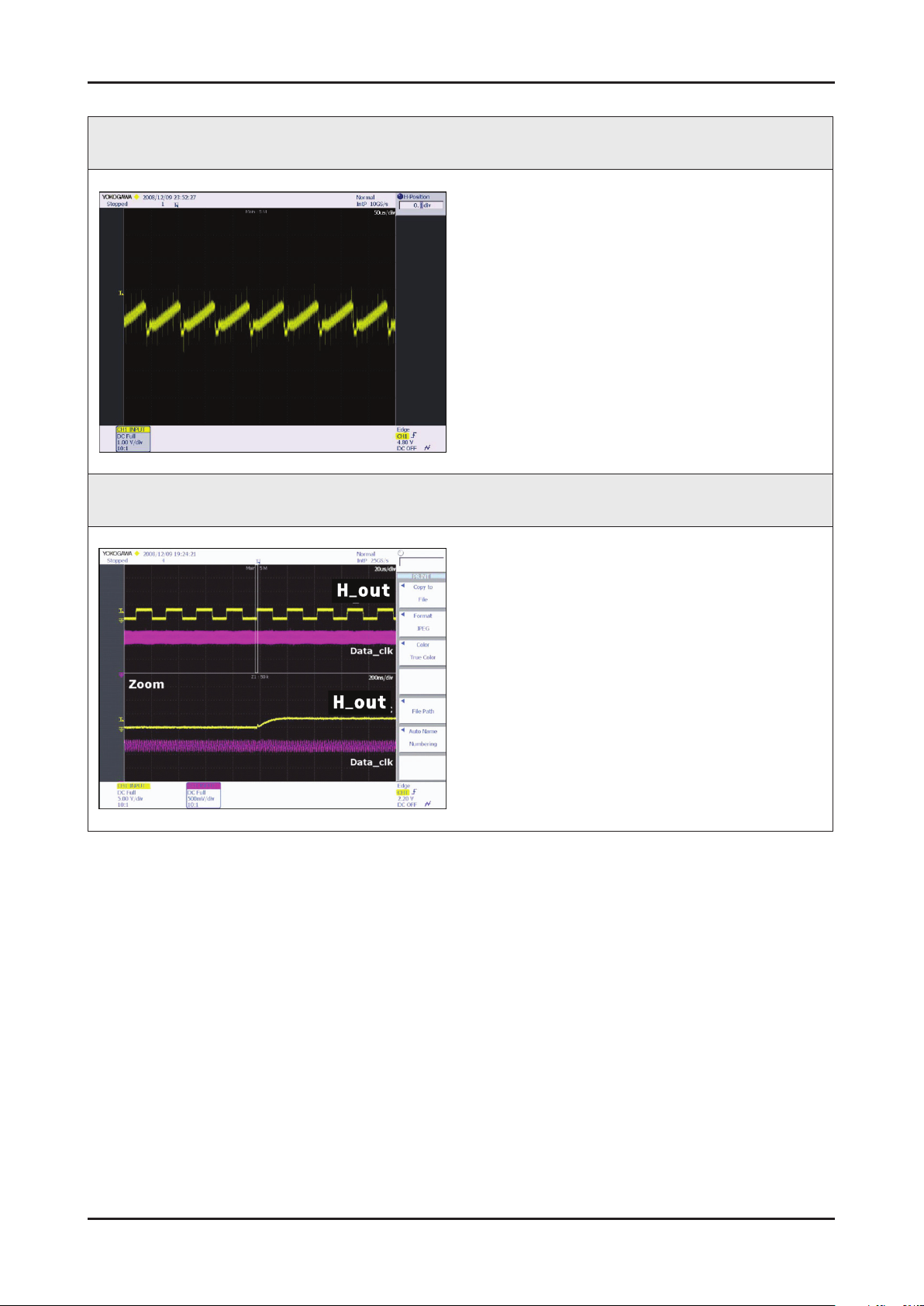
4-18
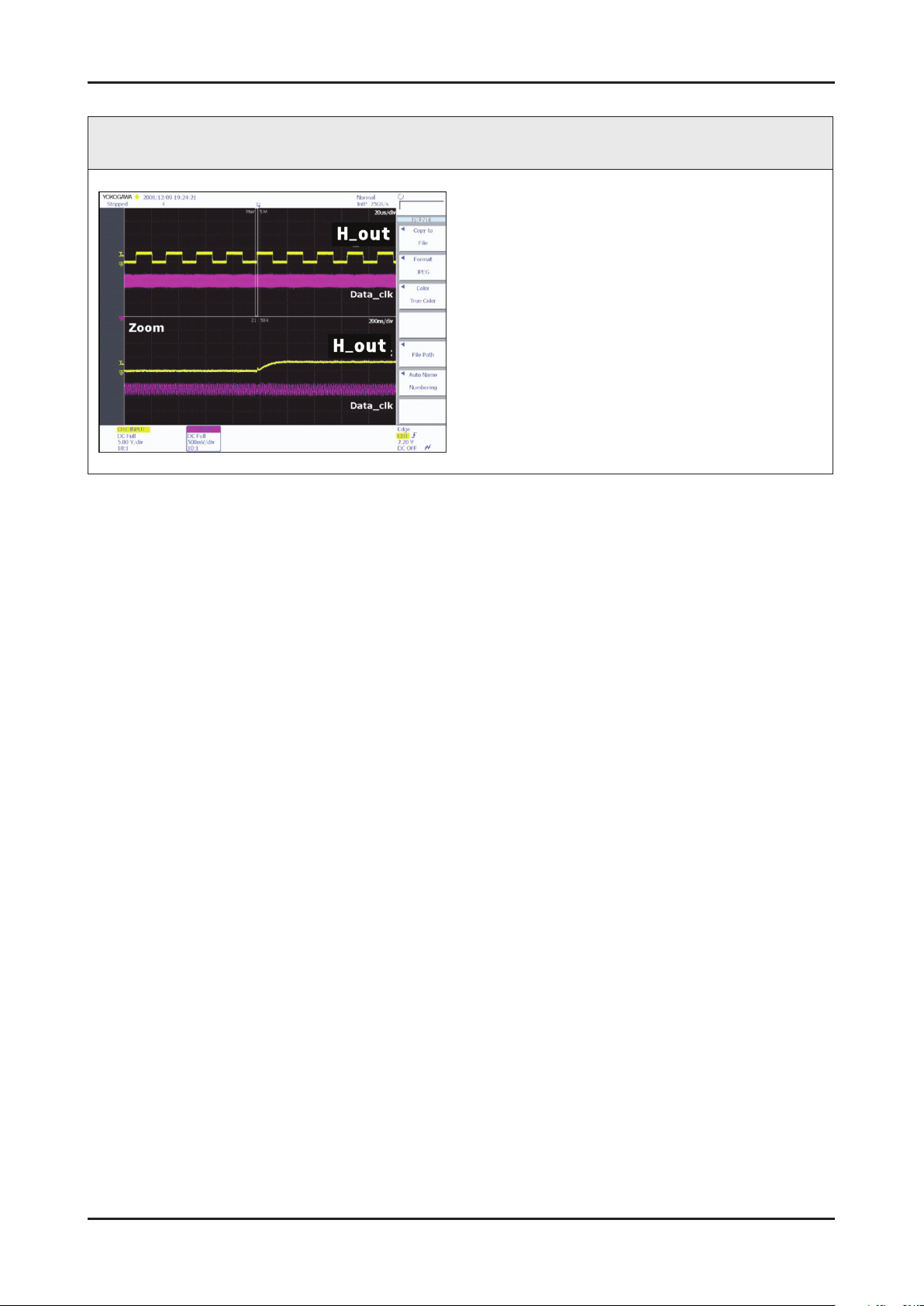
4. Troubleshooting
WAVEFORMS
4 CVBS OUT (Grey Bar)
2 LVDS output
Page 45
4-19
4. Troubleshooting
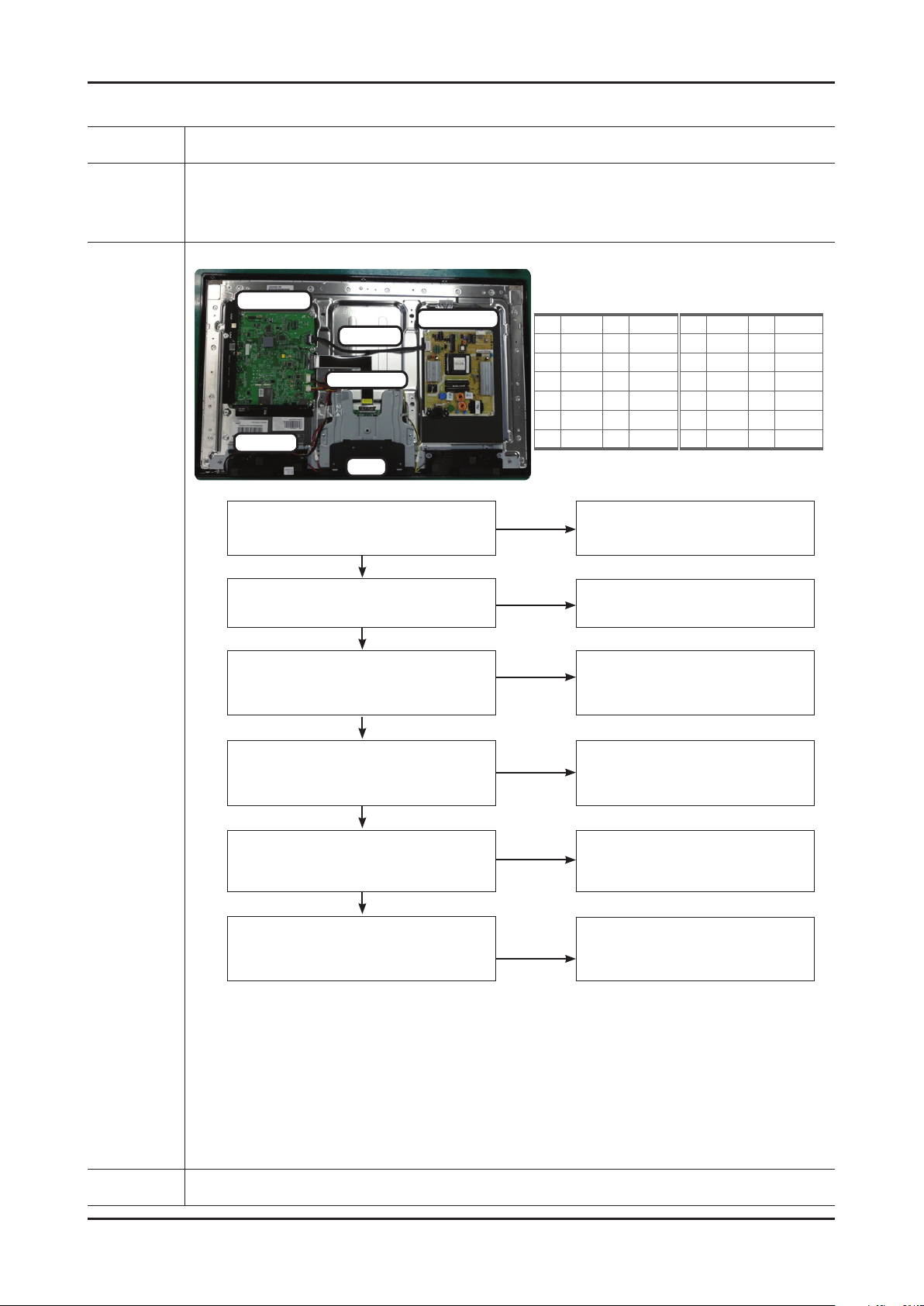
No Video_Component
Symptom Audio is normal but no picture is displayed on the screen. -
Major
checkpoints
Check the Component source -
Check the chelsea. -
This may happen when the LVDS cable connecting the Main Board and the Panel is disconnected. -
Main Ass’y
Power Ass’y
14p cable
LVDS cable
Speaker
T-con
Power indicator LED is off.
Lamp(Backlight) on, no video ?
Yes
Check the component source and check the
connection of component cables (Y,Pb,Pr) ?
Yes
Main Assy
1 B5V 2 SW_PW
3 B5V 4 A5V
5 GND 6 GND
7 B12VS 8 GND
9 B12VS 10 SW_INV
11 B13V 12 NC
13 B13V 14 DMM
No
No
Check a set in the 'Stand-by mode'.
Input the component source properly.
Power Assy
1 B5V 2 SW_PW
3 B5V 4 A5V
5 GND 6 GND
7 B12VS 8 GND
9 B12VS 10 SW_INV
11 B13V 12 NC
13 B13V 14 DMM
Diagnostics
check the Self Diagnosis
(SupportSelf DiagnosisPicture Test)
Dose the promblem still exist self diagnosis ?
Yes
Does the CVBS data appear at
R816/R821(COMP_Y)
R817(COMP_PB)/R815(COMP_PR) ?
Yes
Does the digital data appear at
TP-E_TXCLK+, E_TXCLK- ,
O_TXCLK+, O_TXCLK- ?
Yes
Check the LVDS cable ?
Check the T-Con B'd ?
Replace the LCD panel ?
No
No
No
No
Check external devices and
connections.
Check CN504
Change the Main Assy.
Check IC1001 (X5)
Change the Main Assy.
Please, Contact Tech support.
Caution Make sure to disconnect the power before working on the IP board.
Page 46
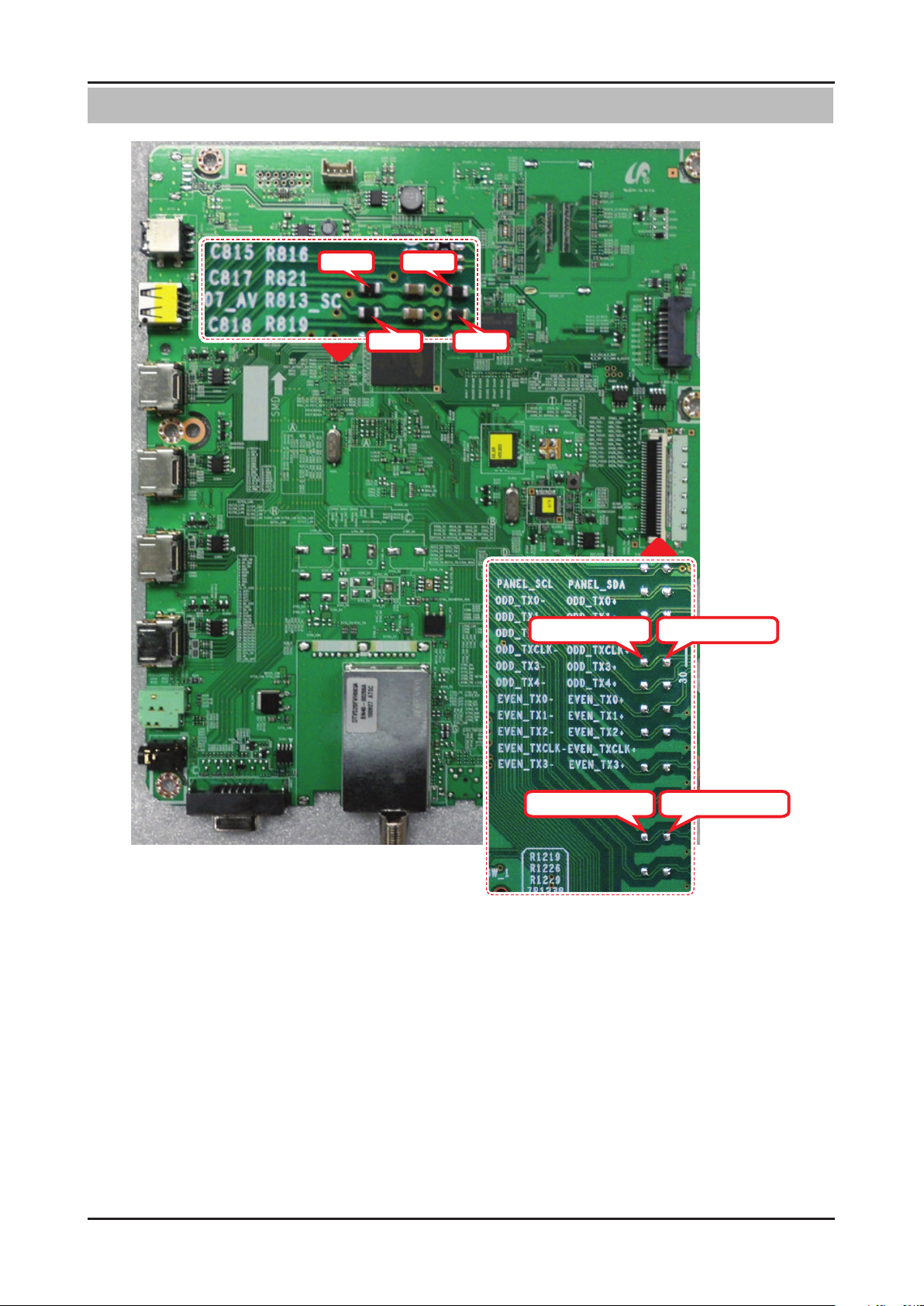
4-20
4. Troubleshooting
Location (Main) - TOP
R816R815
R817
R821
ODD_TXCLK-
ODD_TXCLK+
EVEN_TXCLK-
EVEN_TXCLK+
Page 47
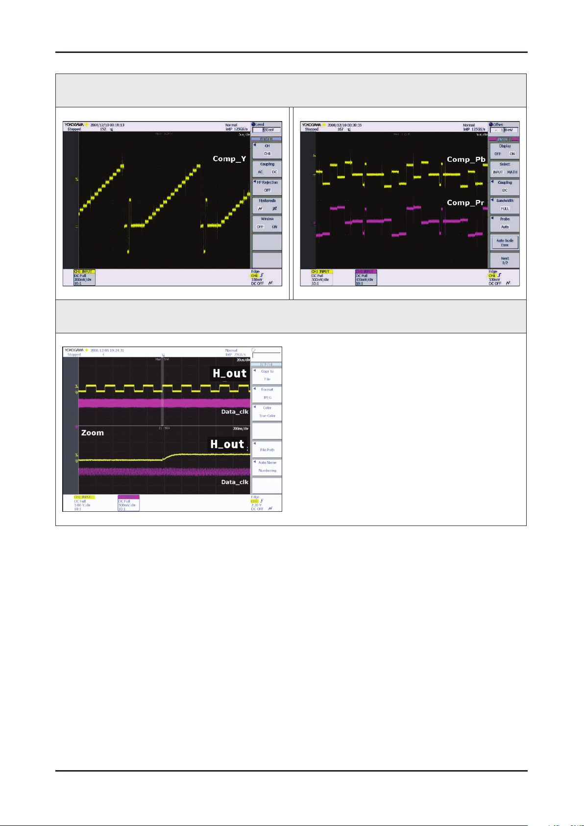
4-21
4. Troubleshooting
WAVEFORMS
5 Compnent_Y (Gray scale) / Pb / Pr (Color bar)
2 LVDS output
Page 48
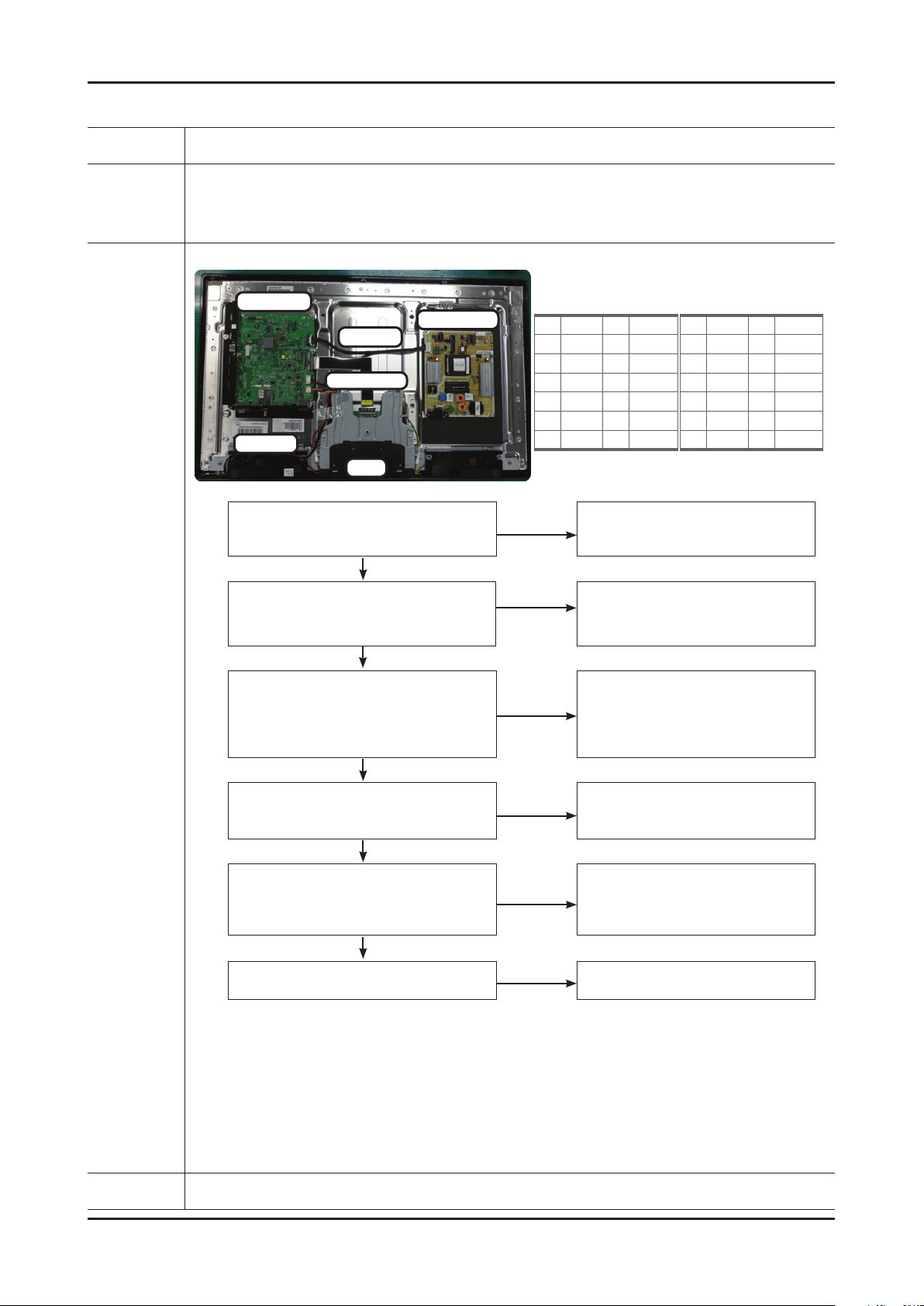
4-22
4. Troubleshooting
No Sound
Symptom Video is normal but there is no sound.. -
Major
checkpoints
When the speaker connectors are disconnected or damaged. -
When the sound processing part of the Main Board is not functioning. -
Speaker defect.. -
Main Ass’y
Power Ass’y
14p cable
LVDS cable
Speaker
T-con
Check the source and check the connection of
sound cable (Comp/PC/DVI to HDMI) ?
Yes
check the Self Diagnosis
(SupportSelf DiagnosisPicture Test)
Dose the promblem still exist self diagnosis ?
Yes
Main Assy
1 B5V 2 SW_PW
3 B5V 4 A5V
5 GND 6 GND
7 B12VS 8 GND
9 B12VS 10 SW_INV
11 B13V 12 NC
13 B13V 14 DMM
No
No
Input the sound source properly.
Check external devices and
Power Assy
1 B5V 2 SW_PW
3 B5V 4 A5V
5 GND 6 GND
7 B12VS 8 GND
9 B12VS 10 SW_INV
11 B13V 12 NC
13 B13V 14 DMM
connections.
Diagnostics
Does the sound data appear at
R524/R525 (AV1, COMP1)
R419/R420 (PC/DVI) ?
Yes
Does the DC B13V
appear at BD209 ?
Yes
Does the sound data appear at
- L-, L+, R-, R+ ?
Yes
Replace speaker ?
No
No
No
No
Check CN504,CN402
Change the Main Assy.
Change the Main Assy.
Check IC1001 (X5)
Check IC301 (Sound AMP)
Change the Main Assy.
Please, Contact Tech support.
Caution Make sure to disconnect the power before working on the IP board.
Page 49
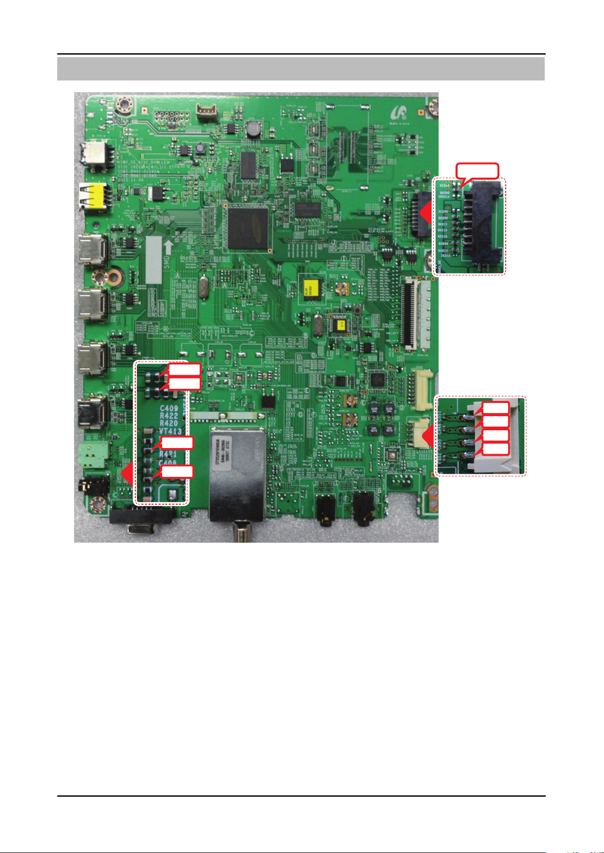
4-23
4. Troubleshooting
Location (Main) - TOP
BD209
R525
R524
R420
R419
L+
L-
R+
R-
Page 50
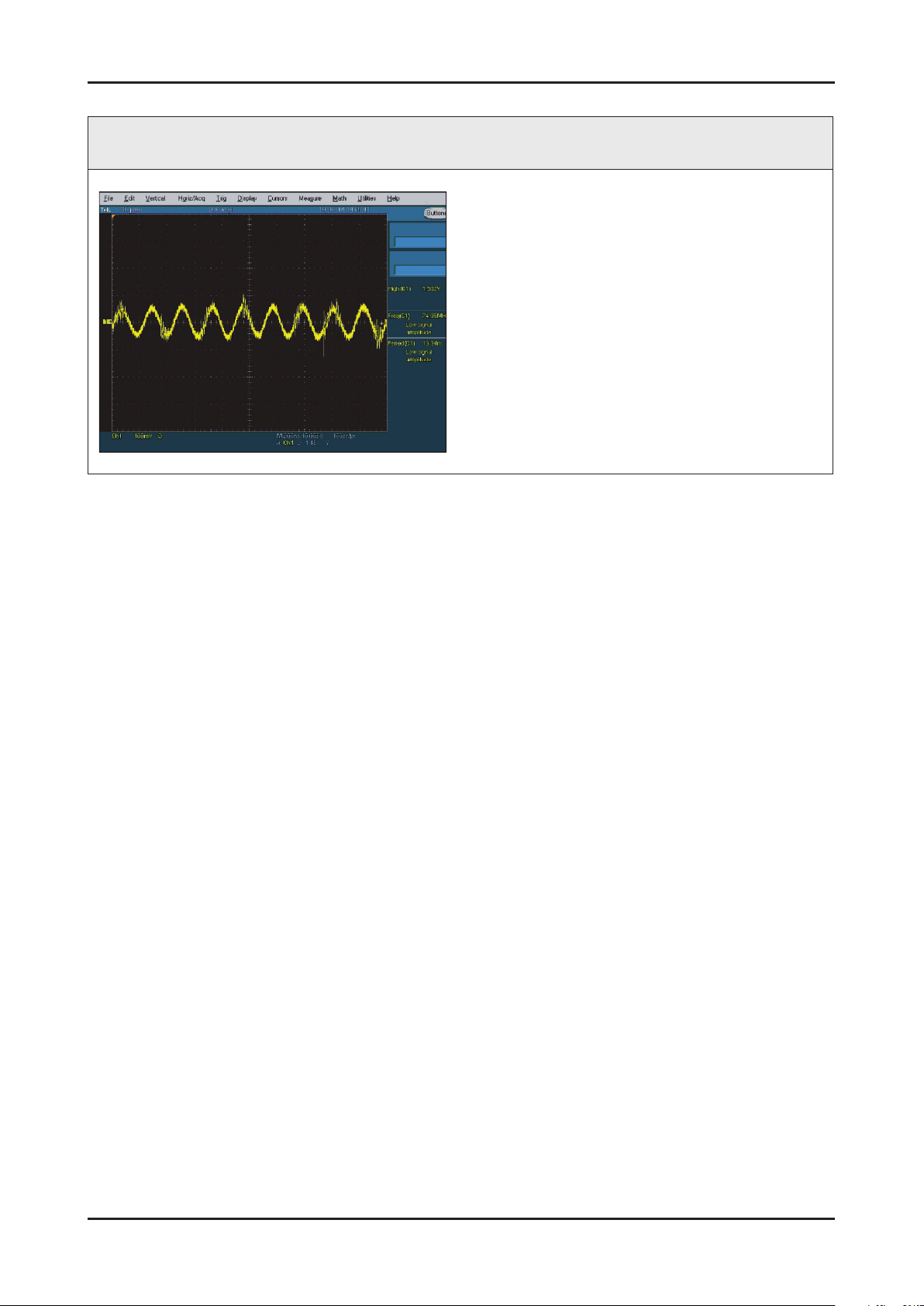
4-24
4. Troubleshooting
WAVEFORMS
7 Speaker OUT
Page 51
4-25
4. Troubleshooting
4-2. Factory Mode Adjustments
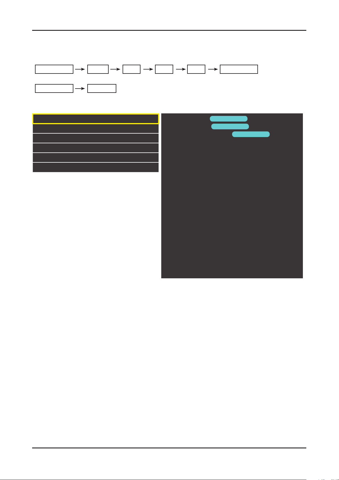
Entering Factory Mode
• If you do not have Factory remote - control
Power OFF 1 8 2 Power ON
• If you do not have Factory remote - control
INFO
If you don’t have Factory remote control, can’t control some menu.
MUTE
Factory
Option
Control
SVC
Expert
ADC/WB
Advanced
T-MST5DCNC-XXX
T-MST5DCNC-XXX
main micom
sub micom
E-Manual : X6DVBHKA-000X
Version
Version
e-manual
Version
EDID SUCCESS
HDCP : SUCCESS
CALIB : AV / COM / PC / HDMI /
Option : XXXX XXXX XXXX X
SDAL-XXX
RFS : Mstar-X6 XXXX
KERNERL MODULE VERSION : "XXXXX_XX"
20XX-XX-XX
TYPE : XXXXXX
MAC Not Available
FACTORY DATA VER : XXX
EERC VERSION : XXX
DTP-AP-COMP-624
DTP-BP-HAl-0117
DTP-BP-0611
DATE OF PURCHASE : XX/XX/XX
Page 52
4-26
4. Troubleshooting
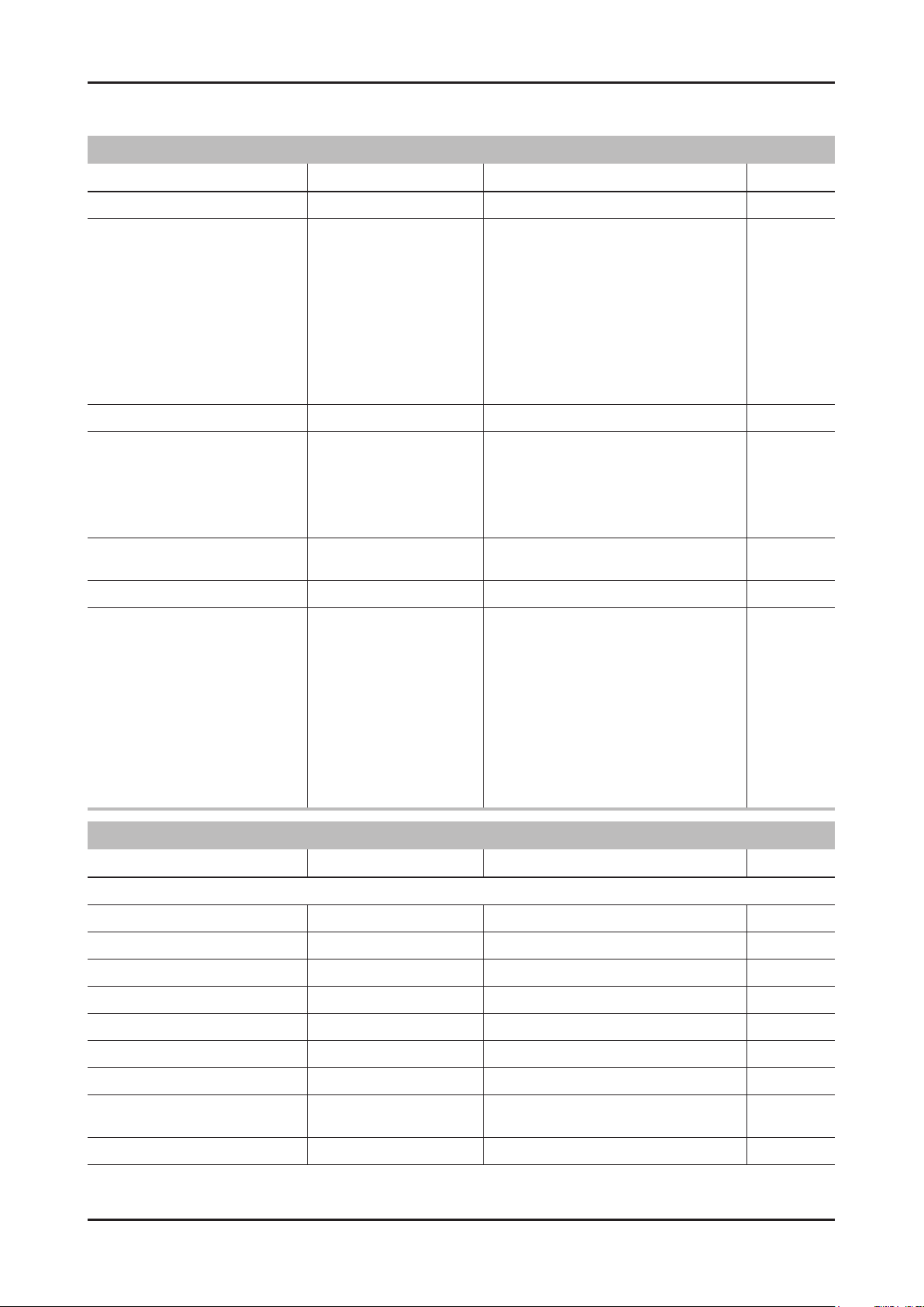
Factory Data
RED - Not adjusted I BLUE - Adjustable
Option
Factory Menu Name Data Range Remark
Factory Reset -
NONE/19A6TH0C/19I6TH0C/22D6AF0
C/22I6AF0C/26A6AH0C/26D6AH0C/32
A6AF0C/32A6AH0C/32D6AF0C/32L6A
H0C/37L6AF0C/40A6AF0C/40L6AF0C/
46A6AF0C/46D6AF0C/19A6AH0E/19P
Type 32A6AF0E / 40A6AF0E
Local set US NONE/US/KOR/SA_ATV
Model UD5500
6AH0E/22D6UF0E/22P6UF0E/23A6UF
0E/24P6UF0E/27A6UF0E/32A6AH0E/
32A6UF0E/32D6AH0E/32D6UF0E/40A
6UF0E/40H6UF0E/46A6UF0E/46D6U
F0E/46DHHcD/51DFHcD/51DHHcD/51DSArD/51DSCrD/59DFHcD/59DSArD
LD400/LD450/LD480/LD550/LD570/
LD580/UD4000/UD4010/UD5000/
UD5500/UD5550/PD450/PD451/PD460/
PD490/PD491PD540/PD541/PD550/
PD551/PD570/PD6400/PD6500/PD6900/
PD7000
TUNER Si_ATC
Ch table NONE NONE/SUWON/SAMEX
Front Color U-T-R-BLK
SEC_ATSC/SEC_TC/ALPS_TC/SI_TCS/
SI_T2/SEC_ISDB/SEC_ATV/SI_ATC/
NONE/P-S-C-BK/P-S-R-BK/P-S-BK/P-SB-BK/P-T-R-BK/P-T-C-BK/P-T-W-Bn/PT-W-Gy/P-T-M-Bn/P-T-C-Gy/P-T-R-Gy/PW-Milk/P-W-M-Wt/P-W-D-Gy/P-W-Vio/LS-C-BK/L-S-R-BK/L-S-BK/L-S-B-BK/L-TR-BK/L-T-C-BK/L-T-W-Bn/L-T-W-Gy/L-TM-Bn/L-T-C-Gy/L-T-R-Gy/L-W-Milk/L-W-
M-Wt/L-W-D-Gy/L-W-Vio/U-S-C-BK/U-SR-BK/U-S-BK/U-S-B-BKU-T-R-BK/U-T-CBK/U-T-W-Bn/U-T-W-Gy/U-T-M-Bn/U-T-CGy/U-T-R-Gy/U-T-BL-M/U-T-CL-M/U-WMilk/U-W-M-Wt/U-W-D-Gy/U-W-Vio/
Control
Factory Menu Name Data Range Remark
EDID
EDID ON/OFF On/Off
EDID WRITE ALL Success/Failure
EDID WRITE PC Success/Failure
EDID WRITE HDMI1 Success/Failure
EDID WRITE HDMI2 Success/Failure
EDID WRITE HDMI3 Success/Failure
EDID WRITE HDMI4 Success/Failure
EDID 1.2 PORT
EDID WRITE DVI
NONE/Not Support/
HDMI2/HDMI3/HDMI4
Page 53
4-27
4. Troubleshooting
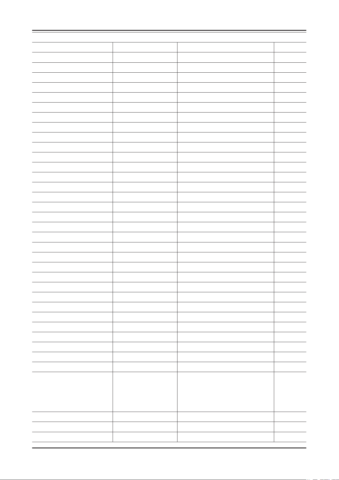
Sub Option
RF Mute Time 600ms 0ms~1000ms
RS-232 Jack UART Debug/Login/UART
Watchdog ON ON/OFF
WD Count 0 0~255
Dimm Type EXT xed
Lvds Format JEIDA JEIDA/VESA/19INCH
Language_Arbic KR KR
TOOLS Support 32 0~255
LNA Support 0 0~255
MediaPlay DB On whth 5MB xed
MediaPlay Movie chapterinMedia xed
MediaPlay DLNA OFF xed
MediaPlay PlayList OFF xed
NETWORK Support EXT_WIFI Not Support/Cable/EXT_WIFI
Info Link Server Type development operationg/development/developing
Info Link Country USA None/USA
TTX List … xed
TTX Group … xed
24Px4 Support OFF ON/OFF
Power Indicator Support OFF ON/OFF
BD Wise Support OFF ON/OFF
Data Service Support OFF ON/OFF
Alternate Del OFF ON/OFF
OTN Server Type operationg operation/development
OTN Test Server OFF OFF/ A/B/C/D/E Zone
OTN Support ON ON/OFF
OTN Reset
OTN Duration OFF ON/OFF
OTN Fail Test OFF ON/OFF
IIC Bus Stop OFF ON/OFF
Visual Test Disable xed
Emergency Log Copy
Checksum 0x0000
View Log
Select Log Type IR Key NVRAM / DIAGNOSIS / IR KEY
Log View
Delete Log
ColorSpace Support RGB Type RGB Type / HueSate Type
Gemstar On/Off OFF ON/OFF
WSS Support OFF ON/OFF
Page 54
4-28
4. Troubleshooting
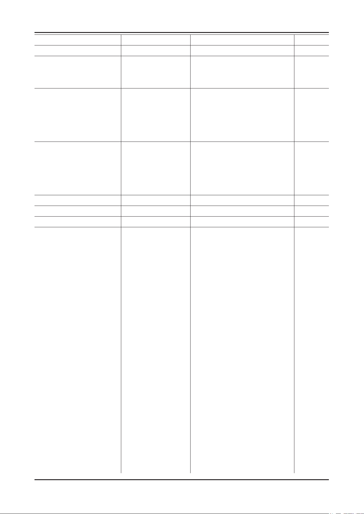
PVR Support OFF ON/OFF
CI Support OFF ON/OFF
Eeprom Reset
EER Reset
NVR All Clear OFF
Spread Spectrum
LVDS Spread ON ON/OFF
Period 40K 30K/40K/50K/60K
Amplitude 1.5 0.0/0.5/1.0/1.5/2.0/2.5/3.0
DDR Spread 1% 0.1~2.0%
DDR Margin
A CTRL_OFFSET_0_3 0X0
A CTRL_OFFSET_D 0X0
B CTRL_OFFSET_0_3 0X0
B CTRL_OFFSET_D 0X0
H.264 Margin 8 0~2000
MPEG Margin 1000 0~2001
Tuner Margin 10 0~2002
SST
Y0 Ref 166 0~255
Y1 Ref 148 0~255
Y2 Ref 119 0~255
Y3 Ref 101 0~255
Y4 Ref 76 0~255
Y5 Ref 60 0~255
Y6 Ref 31 0~255
Y7 Ref 0 0~255
Cb0 Ref 128 0~255
Cb1 Ref 64 0~255
Cb2 Ref 148 0~255
Cb3 Ref 85 0~255
Cb4 Ref 171 0~255
Cb5 Ref 108 0~255
Cb6 Ref 194 0~255
Cb7 Ref 0 0~255
Cr0 Ref 128 0~255
Cr1 Ref 137 0~255
Cr2 Ref 64 0~255
Cr3 Ref 74 0~255
Cr4 Ref 181 0~255
Cr5 Ref 192 0~255
Page 55
4-29
4. Troubleshooting
Cr6 Ref 118 0~255
Cr7 Ref 0 0~255
SST_Th
Y0 TH 20 0~255
Y1 TH 20 0~255
Y2 TH 20 0~255
Y3 TH 20 0~255
Y4 TH 20 0~255
Y5 TH 20 0~255
Y6 TH 20 0~255
Y7 TH 20 0~255
Cb0 TH 20 0~255
Cb1 TH 20 0~255
Cb2 TH 20 0~255
Cb3 TH 20 0~255
Cb4 TH 20 0~255
Cb5 TH 20 0~255
Cb6 TH 20 0~255
Cb7 TH 20 0~255
Cr0 TH 20 0~255
Cr1 TH 20 0~255
Cr2 TH 20 0~255
Cr3 TH 20 0~255
Cr4 TH 20 0~255
Cr5 TH 20 0~255
Cr6 TH 20 0~255
Cr7 TH 20 0~255
2nd mips ON ON/OFF
2nd mips count 0 0~255
Region KOR xed
PnP Language ENG_US ENG_US/SPA_US/FRA_US
PC Auto Ident Enable Auto/Enable
OTP Lock … xed
Auto Power ON ON/OFF
Key Sensitivity 27 0~255
FANET OFF ON/OFF
S-Micom Upgrade OFF ON/OFF
Page 56
4-30
4. Troubleshooting
Hotel Option
Hotel Mode OFF ON/OFF
Samsung/2M/Locatel/VDA/VDA-S/Acentic/
Premiere/Sustinere/Quadriga/ETV/Ibahn/
SI Vender Samsung
Power On Channel 3 1~135
Channel Type ATV ATV/DTV/CATV/CDTV
Power On Volume 10 0~100
Min Volume 0 0~100
Max Volume 100 0~100
Panel Button Lock Unlock Unlock/Lock/OnlyPower
Magilink/Otrum/PeninsulaSiemens/OCC/MTI/
MstreamsDAWNXTV/Enseo/Cardinal/Guestek/
OFF/Movielink/Swisscom
Power On Source TV
Shop Option
Shop Mode OFF ON/OFF
Exhibition Mode OFF ON/OFF
Asia Option
TTX OFF ON/OFF
China HD OFF ON/OFF
NT Conversion OFF ON/OFF
Sepco 120Hz OFF ON/OFF
Unbalance OFF ON/OFF
FMTransmitter Support OFF ON/OFF
FMTransmitter Carrier OFF ON/OFF
AF Level adjust 3 0~7
TX Power Level 0 0~3
Mono Last Memory OFF ON/OFF
Sound
TV/AV/Comp/PC/HDMI1/HDMI2/HDMI3/
HDMI4
High Devi OFF ON/OFF
Carrier_Mute ON ON/OFF
Volume Curve Type2 Type1/Type2/error
Speaker Delay Normal 10 0~255
Pilot Level High Thld 0x08h 0x00~0xff
Pilot Level Low Thld 0x05h 0x00~0xff
FM Prescale 17 0~255
AM Prescale 10 0~255
NICAM Prescale 33 0~255
Amp Volume 0x10h 0x00~0xff
Amp Scale 0x78h 0x00~0xff
Amp Check Sum 0x0000a820 xed
Woofer Type 4 1~7
Page 57
4-31
4. Troubleshooting
Woofer Scale 0x7Fh 0x00~0xff
Woofer Check Sum
Speaker EQ ON ON/OFF
PEQ Test 0 0~7
Amp Model NTP7300 SAT369B/TAS5715/NPT7300
Speaker cut-off Freq 4 0~16
SPDIF PCM Gain -9dB -10dB~0dB
BTSC Mono Prescale 0 -10~10
BTSC streo Prescale 0 -10~10
SAO Prescale 0 -10~10
A2 Ident High Thld 0 -10~10
A2 Ident Low Thld 0 -10~10
Carrier2 Amp High Thld 0 -10~10
Carrier2 Amp Low Thld 0 -10~10
Carrier2 SNR High THR 0 -10~10
Carrier2 SNR Low THR 0 -10~10
Cong Option
Num of ATV 1 1~2
Num of DTV 1 0~2
Num of AV 2 0~3
Num of SVIDEO 0 1~3
Num of Comp 2 1~3
Num of HDMI 4 0~4
Num of PC 1 0~1
Num of SCART 0 0~2
Num of DVI 0 0~1
Num of OPTICAL Link 0 xed
Num of MEDIA 1 0~1
Num of PANEL KEY 6 0~8
Num of USB Port 2 0~2
Num of HeadPhone 0 0~1
MFT Offset 62.5 50/62.5
Select LCD/PDP LCD LCD/PDP
HDMI/DVI SEL 1 1~4
Indicator Led OFF ON/OFF
Wall Mount OFF ON/OFF
HV Flip ON ON/OFF
Num of Display 2 1~2
DVI/HDMI SOUND Auto Auto/DVI
HDMI HOT PLUG Disable Enable/Disable
HOTPLUG SWITCHING Boot Disable/Boot/Source
Page 58
4-32
4. Troubleshooting
HOTPLUG DURATION 1200ms 0~2000ms
CLK TERM DURATION 1200ms 0~2000ms
HDMI FLT CNT SIG 200ms 0~1000ms
HDMI FLT CNT LOS 600ms 0~1000ms
UNSTABLE BAN CNT 3500ms 0~100000ms
HDMI Err Cnt 5 0~10
HDMI ROBIN ON ON/OFF
HDMI Callback OFF ON/OFF
HDMI CTS Thld 8 0~15
HDMI CTS Cnt1 1 0~15
TMDS_EQ2_Boost 1 0~7
TMDS_EQ2_Gain 0 0~3
TMDS_PLL_Loop 3 0~3
TMDS_CPREG_BLEED 1 0~1
HDMI EQ AUTO AUTO/Low/Middle/High/Strong
HDMI Write Type Combine Combine/Separate
HDMI Switch SIL9287 NONE/SIL9287/TMDS461
DVI SET TIME 300ms 0~1000ms
Type Of PANEL KEY Horizontal Horzontal/Vertical/PDPVertical/Nne
EcoSensor Support ON ON/OFF
LEDMotionPlus Support OFF ON/OFF
Natural Mode Support ON ON/OFF
All Share Support ON ON/OFF
Relax Mode Support OFF ON/OFF
DVI-I Support … xed
Melfas Function Support … xed
Light Level Support … xed
SCC
SCC Mode Dynamic Dynamic/Movie
SCC ON/OFF OFF ON/OFF
SCC Input Data
Hx 272 0~512
Hy 273 0~512
Lx 274 0~512
Ly 275 0~512
sSCC Const
sSCC Hx 550 0~1024
sSCC Hy 566 0~1024
sSCC Lx 598 0~1024
sSCC Ly 550 0~1024
Page 59

4-33
4. Troubleshooting
pSCC Const
pSCC Hx 550 0~1024
pSCC Hy 566 0~1024
pSCC Lx 598 0~1024
pSCC Ly 550 0~1024
SCC Source Data PBA PBA/PANEL
SWAP PBA PBA/PANEL
SVC
Factory Menu Name Data Range Remark
Test Pattern
Pattern Sel OFF OFF/ White/Grey/Black/Red/Green/Blue
Logic Pattern Sel … xed
Logic Level Sel … xed
Panel Auto Setting Success
Panel Display Time 22Hr
Logic Usb D/L Off
Tuner Status
DVB
SNR
BER
Singal Strength
Bandwidth
Frequency
LNA Status
FFT
Modulation
Code Rate
GI
Hier Modulation
Frequency Offset
Timing Offset
AGC
UCB
PLL Type
DEMOD Type
TPS LOCK
RS Lock
SSI
SQI
Page 60
4-34
4. Troubleshooting
ISDB-T
FFT Size_1
Guard Interval_1
Freq. Offset_1
SNR_1
IF AGC_1
TMCC Lock_1
TS Packet_1
Master Lock_1
A_Modulation_1
A_Code Rate_1
A_Timer InterLeave_1
A_Segments Num_1
A_Ber_1
B_Modulation_!
B_Code Rate_1
B_Timer InterLeave_1
B_Segments Num_1
B_BER_1
C_Modulation_1
C_Code Rate_1
C_Timer InterLeave_1
C_Segments Num_1
C_BER_1
T-CON Usb Download Failire
ADC/WB
Factory Menu Name Data Range Remark
ADC
AV Calibration Success Success / Failure
Comp Calibraion Success Success / Failure
PC Calibration Success Success / Failure
HDMI Calibration Success Success / Failure
ADC Target
1st_AV_Low 64 0 ~ 1020
1st_AV_High 880 0 ~ 1020
1st_AV_Delta 2 0 ~ 7
1st_COMP_Y_Low 64 0 ~ 1020
1st_COMP_Cb_Low …
1st_COMP_Cr_Low …
1st_COMP_Y_High 940 0 ~ 1020
1st_COMP_Cb_High …
Page 61
4-35
4. Troubleshooting
1st_COMP_Cr_High …
1st_COMP_Delta 2 0~7
1st_PC_R_Low 16 0 ~ 1020
1st_PC_G_Low …
1st_PC_B_Low …
1st_PC_R_High 1004 0 ~ 1020
1st_PC_G_Low …
1st_PC_B_Low …
1st_PC_Delta 2 0~7
2nd_AV_R_Low 4 xed
2nd_AV_G_Low 4 xed
2nd_AV_B_Low 4 xed
2nd_AV_R_High 940 xed
2nd_AV_G_High 940 xed
2nd_AV_B_High 940 xed
2nd_AV_Delta 2 0~7
2nd_COMP_R_Low 4 xed
2nd_COMP_G_Low 4 xed
2nd_COMP_B_Low 4 xed
2nd_COMP_R_High 940 xed
2nd_COMP_G_High 940 xed
2nd_COMP_B_High 940 xed
2nd_COMP_Delta 2 0~7
2nd_PC_R_Low 4 xed
2nd_PC_G_Low 4 xed
2nd_PC_B_Low 4 xed
2nd_PC_R_High 940 xed
2nd_PC_G_High 940 xed
2nd_PC_B_High 940 xed
2nd_PC_Delta 2 0~7
2nd_HDMI_R_Low 4 xed
2nd_HDMI_G_Low 4 xed
2nd_HDMI_B_Low 4 xed
2nd_HDMI_R_High 940 xed
2nd_HDMI_G_High 940 xed
2nd_HDMI_B_High 940 xed
2nd_HDMI_Delta 2 0~7
ADC Result
1st_Y_GH 0 xed
1st_Y_GL 0 xed
1st_Cb_BH 0 xed
Page 62
4-36
4. Troubleshooting
1st_Cb_BL 0 xed
1st_Cr_RH 0 xed
1st_Cr_RL 0 xed
2nd_R_L 134 0 ~ 255
2nd_G_L 134 0 ~ 255
2nd_B_L 134 0 ~ 255
2nd_R_H 49 0 ~ 255
2nd_G_H 49 0 ~ 255
2nd_B_H 49 0 ~ 255
White Balance
Sub Brightness 128 0 ~ 1023
R-Offset 512 0 ~ 1023
G-Offset 512 0 ~ 1023
B-Offset 512 0 ~ 1023
Sub Contrast 128 0 ~ 1023
R-Gain 512 0 ~ 1023
G-Gain 512 0 ~ 1023
B-Gain 512 0 ~ 1023
Movie R-Offset … xed
Movie B-Offset … xed
Movie R-Gain … xed
Movie B-Gain … xed
Page 63
4-37
4. Troubleshooting
4-3. White Balance - Calibration
4-3-1. White Balance -Calibration
Factory
ADC / WB
AV Calibration
Comp Calibration
PC Calibration
HDMI Calibration
4-3-2. Service Adjustment
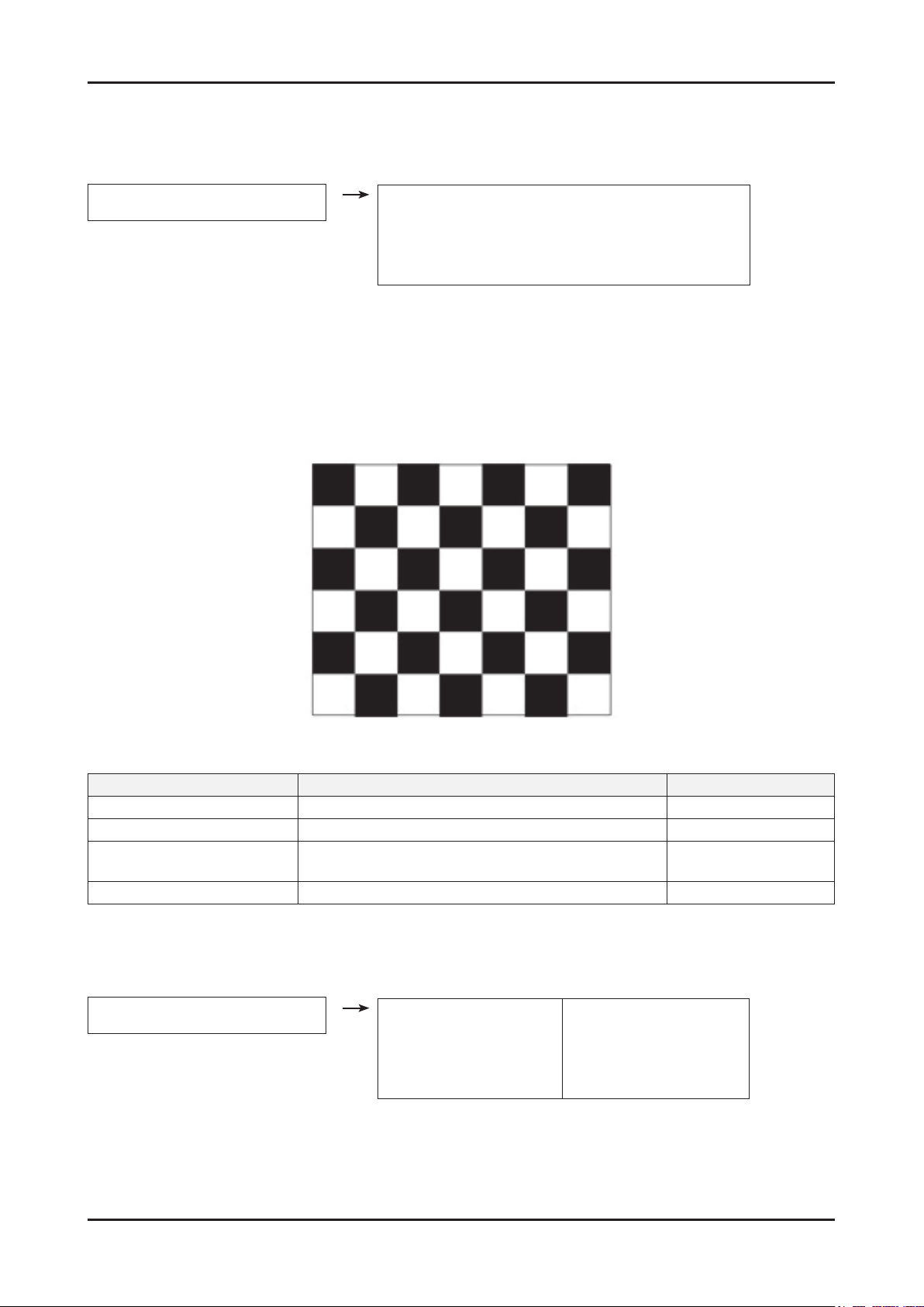
- You must perform Calibration in the Lattice Pattern before adjusting the White Balance.
Color Calibration
Adjust spec.
Source : HDMI1.
Setting Mode : 1280*720@60Hz2.
Pattern : Pattern #24 (Chess Pattern)3.
Use Equipment : CA210 & Master MSPG925 Generator4.
Use other equipment only after comparing The result with that of The Master equipment.
Input mode Calibration Pattern
CVBS IN (Model_#1) Perform in NTSC B&W Pattern #24 Lattice
Component IN (Model_#6) Perform in 720p B&W Pattern #24 Lattice
PC Analog IN (Model_#21) Perform in VESA XGA (1024x768) B&W Pattern #24 Lattice
HDMI IN Perform in 720p B&W Pattern #24 Lattice
4-3-3. White Balance - Adjustment
Factory (Low light) (High light)
ADC / WB - White Balance
Sub Bright
R offset
G offset
B offset
Sub Contrast
R gain
G gain
B gain
Page 64

4-38
4. Troubleshooting
Method of Color Calibration (AV)
1) Apply the NTSC Lattice (N0. 3) pattern signal to the AV IN 1 port.
2) Press the Source key to switch to “AV1” mode.
3) Enter Service mode.
4) Select the “ADC” menu.
5) Select the “AV Calibration” menu.
6) In “AV Calibration Off” status, press the “ ” key to perform Calibration.
7) When Calibration is complete, it returns to the high-level menu.
8) You can see the change of the “AV Calibration” status from Failure to Success.
Method of Color Calibration (Component)
1) Apply the 720p Lattice (N0. 6) pattern signal to the Component IN 1 port.
2) Press the Source key to switch to “Component1” mode.
3) Enter Service mode.
4) Select the “ADC” menu.
5) Select the “Comp Calibration” menu.
6) In “Comp Calibration Off” status, press the “ ” key to perform Calibration.
7) When Calibration is complete, it returns to the high-level menu.
8) You can see the change of the “Comp Calibration” status from Failure to Success.
Method of Color Calibration (PC)
1) Apply the VESA XGA Lattice (N0. 21) pattern signal to the PC IN port.
2) Press the Source key to switch to “PC” mode.
3) Enter Service mode.
4) Select the “ADC” menu.
5) Select the “PC Calibration” menu.
6) In “PC Calibration Off” status, press the “ ” key to perform Calibration.
7) When Calibration is complete, it returns to the high-level menu.
8) You can see the change of the “PC Calibration” status from Failure to Success.
Method of Color Calibration (HDMI)
1) Apply the 720p Lattice (N0. 6) pattern signal to the HDMI1/DVI IN port.
2) Press the Source key to switch to “HDMI1” mode.
3) Enter Service mode.
4) Select the “ADC” menu.
5) Select the “HDMI Calibration” menu.
6) In “HDMI Calibration Off” status, press the “ ” key to perform Calibration.
7) When Calibration is complete, it returns to the high-level menu.
8) You can see the change of the “HDMI Calibration” status from Failure to Success.
Page 65
4-39
4. Troubleshooting
4-4. White Ratio (Balance) Adjustment
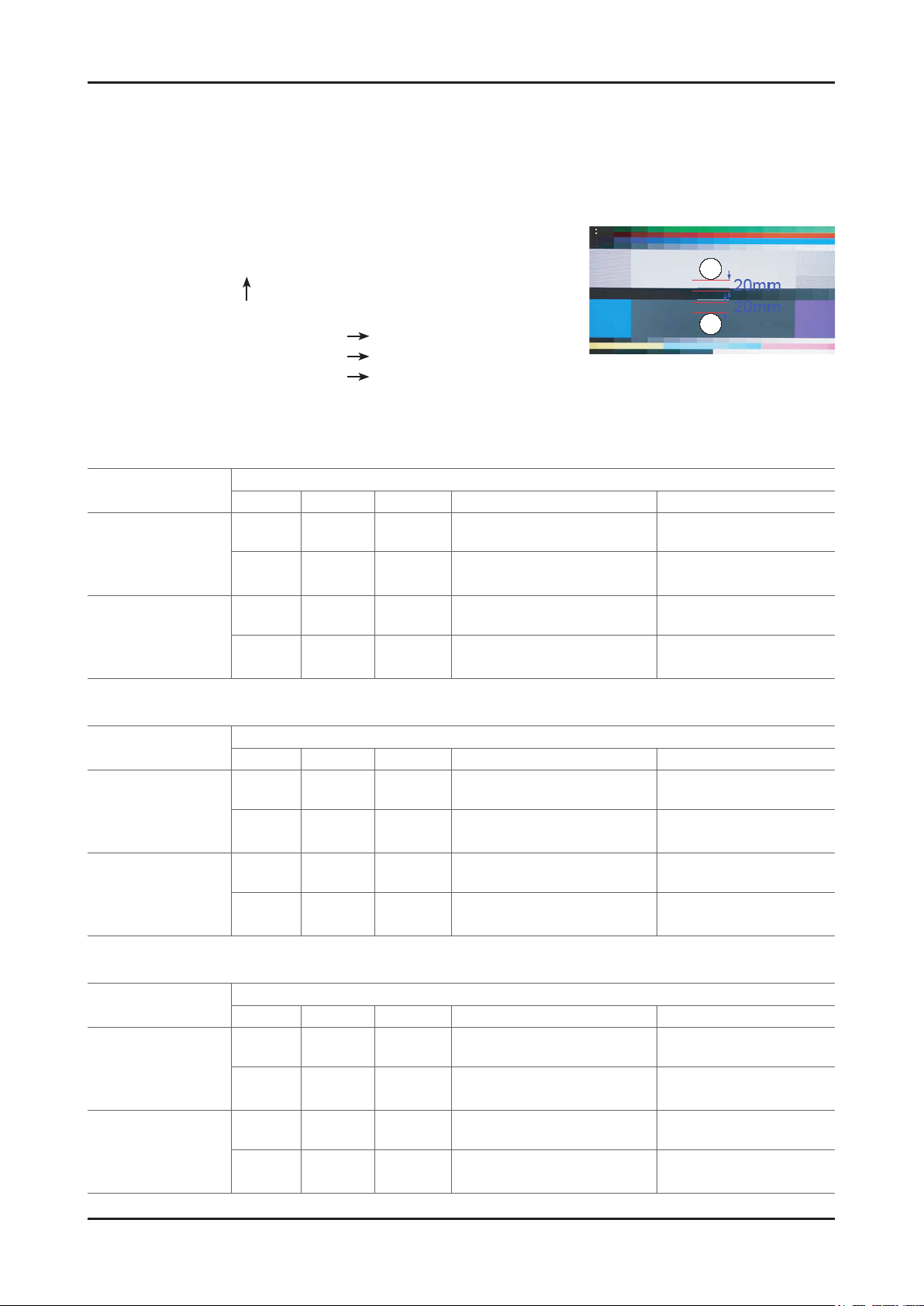
You can adjust the white ratio in factory mode (1:Calibration, 3:White-Balance).1.
Since the adjustment value and the data value vary depending on the input source, you have to adjust these in CVBS, 2.
Component 1 and HDMI 1 modes.
The optimal values for each mode are congured by default. (Refer to Table 1, 2) 3.
It varies with Panel’s size and Specication.
- Equipment : CS-210
- Pattern: MIK K-7256 #92 “Flat W/B Pattern" as standard.
-
Use other equipment only after comparing the result with that of the Master equipment.
- Set Aging time : 60min
- Calibration and Manual setting for WB adjustment.
HDMI : Calibration at #24 Chessboard Pattern Manual adjustment #92 pattern (720p)
COMP: Calibration at #24 Chessboard Pattern
CVBS: Calibration at #24 Chessboard Pattern
-
If nishing in HDMI mode, adjustment coordinate is almost same in AV/COMP mode.
- White Balance Manual Adjustment
UN32D5500RF (AMLCD)
Manual adjustment at #92 pattern (720p)
Manual adjustment at #92 pattern (NTSC)
P-Mode
[Dynamic Cool1]
HDMI
Comp
CVBS
[Movie Warm2]
HDMI
Comp
CVBS
UN32D5500RF (CMI)
P-Mode
[Dynamic Cool1]
HDMI
Comp
CVBS
[Movie Warm2]
HDMI
Comp
CVBS
x y Y(Luminance) T(K)+MPCD
H/L 272 278
L/L 272 278
H/L 313 329
L/L 329 329
x y Y(Luminance) T(K)+MPCD
H/L 264 274
L/L - -
H/L 313 329
L/L - -
Adjustment Coordinate CA-210
45.6 fL
(Sub_CT : 128 Fix)
3.2fL
(Sub_Brt : 128 Fix)
20.8 fL
(M_Sub_CT : 128 Fix)
1.4 fL
(M_Sub_Brt : 128 Fix)
Adjustment Coordinate CA-210
41 fL
(Sub_CT : 134 Fix)
2.8fL
(Sub_Brt : 128 Fix)
32 fL
(M_Sub_CT : 128 Fix)
1.8 fL
(M_Sub_Brt : 128 Fix)
12,000(+-0)
12,000(+-0)
6,500(+-0)
6,500(+-0)
16,000(+-0)
16,000(+-0)
6,500(+-0)
6,500(+-0)
UN40D5500RF
P-Mode
[Dynamic Cool1]
HDMI
Comp
CVBS
[Movie Warm2]
HDMI
Comp
CVBS
x y Y(Luminance) T(K)+MPCD
H/L 272 278
L/L 272 278
H/L 313 329
L/L 329 329
Adjustment Coordinate CA-210
48.6 fL
(Sub_CT : 128 Fix)
2.9fL
(Sub_Brt : 128 Fix)
22.3 fL
(M_Sub_CT : 128 Fix)
1 fL
(M_Sub_Brt : 128 Fix)
12,000(+-0)
12,000(+-0)
6,500(+-0)
6,500(+-0)
Page 66
4-40
4. Troubleshooting
4-5. RS-232C
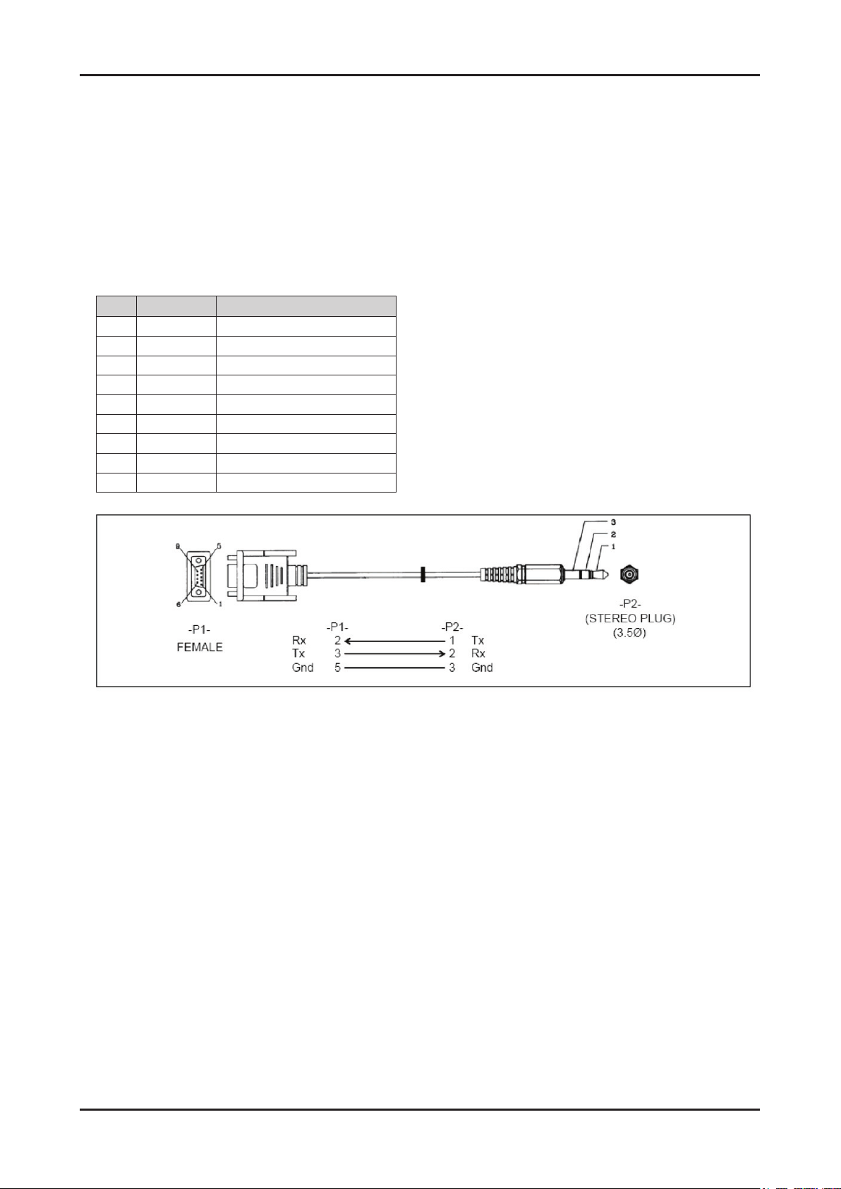
1. RS232C Control
Port : COM#(Serial)
Bit rate : 115200
Data Bit : 8 bit
Parity : None
Stop Bits : 1
Flow Control : None
2. Description of RS232C
Pin# Name Full Name
1 CD Carrier Detect
2 RxD Received Data
3 TxD Transmitted Data
4 DTR Data Terminal Ready
5 GND Signal Ground
6 DSR Data Set Ready
7 RTS Request To Send
8 CTS Clear To Send
9 RI Ring Indicator
Page 67
4-41
4. Troubleshooting
4-6. AV control code
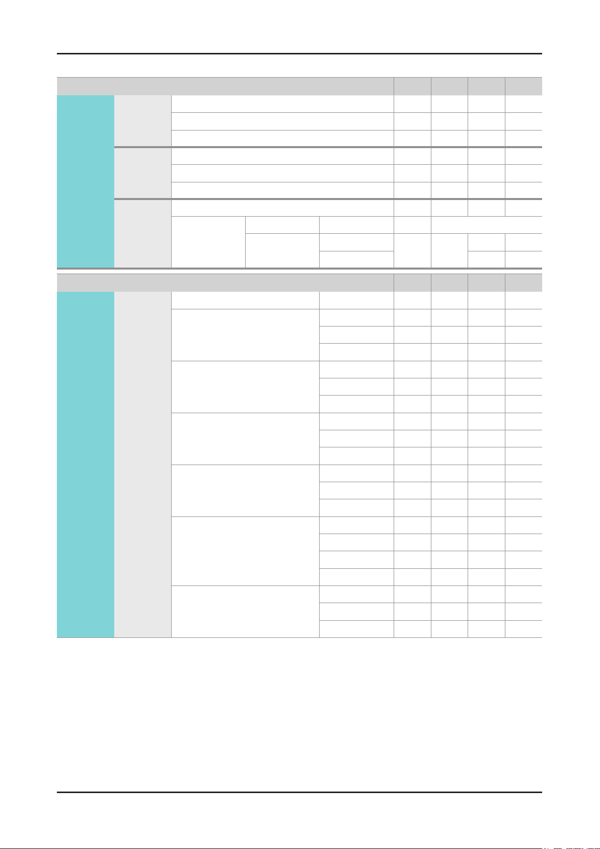
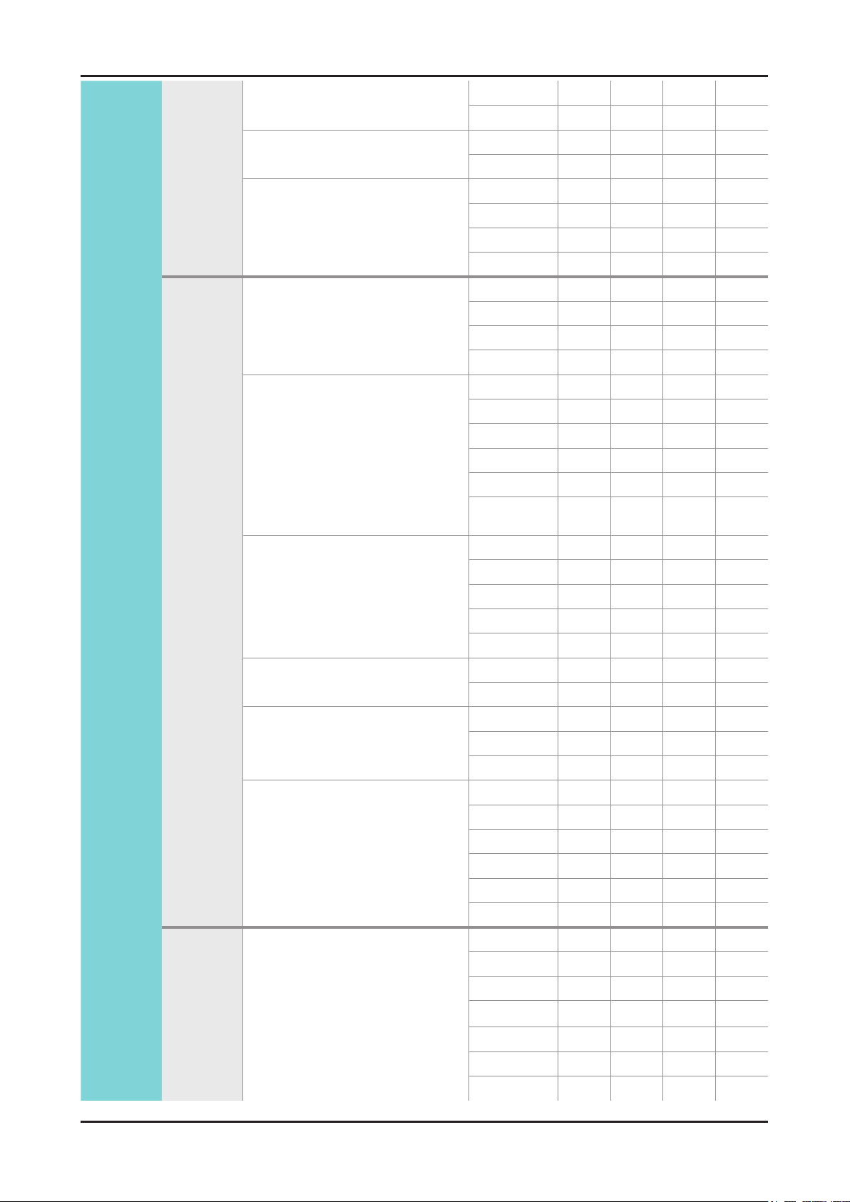
Control Item Cmd1 Cmd2 Cmd3 Value
General Power Power 0x00 0x00 0x00 0x00
Off 0x01
On 0x02
Volume Direct 0x01 0x00 0x00
Up 0x01 0x00
Down 0x02 0x00
Mute 0x02 0x00 0x00 0x00
Ch. Direct 0x04 -
Continuous Up
0x03 0x00
Down 0x02 0x00
0x01 0x00
(0~100)
Control Item Cmd1 Cmd2 Cmd3 Value
Input Source List TV TV 0x0a 0x00 0x00 0x00
AV1 0x01 0x00
AV
S-Video
Component Component1 0x03 0x00
AV2 0x01
AV3
S-Video1 0x02 0x00
S-Video2 0x01
S-Video3 0x02
Component2 0x01
0x02
Component3 0x02
PC PC1 0x04 0x00
PC2 0x01
PC3 0x02
HDMI HDMI1 0x05 0x00
HDMI2 0x01
HDMI3 0x02
HDMI4 0x03
DVI DVI1 0x06 0x00
DVI2 0x01
DVI3 0x02
Page 68
4-42
4. Troubleshooting
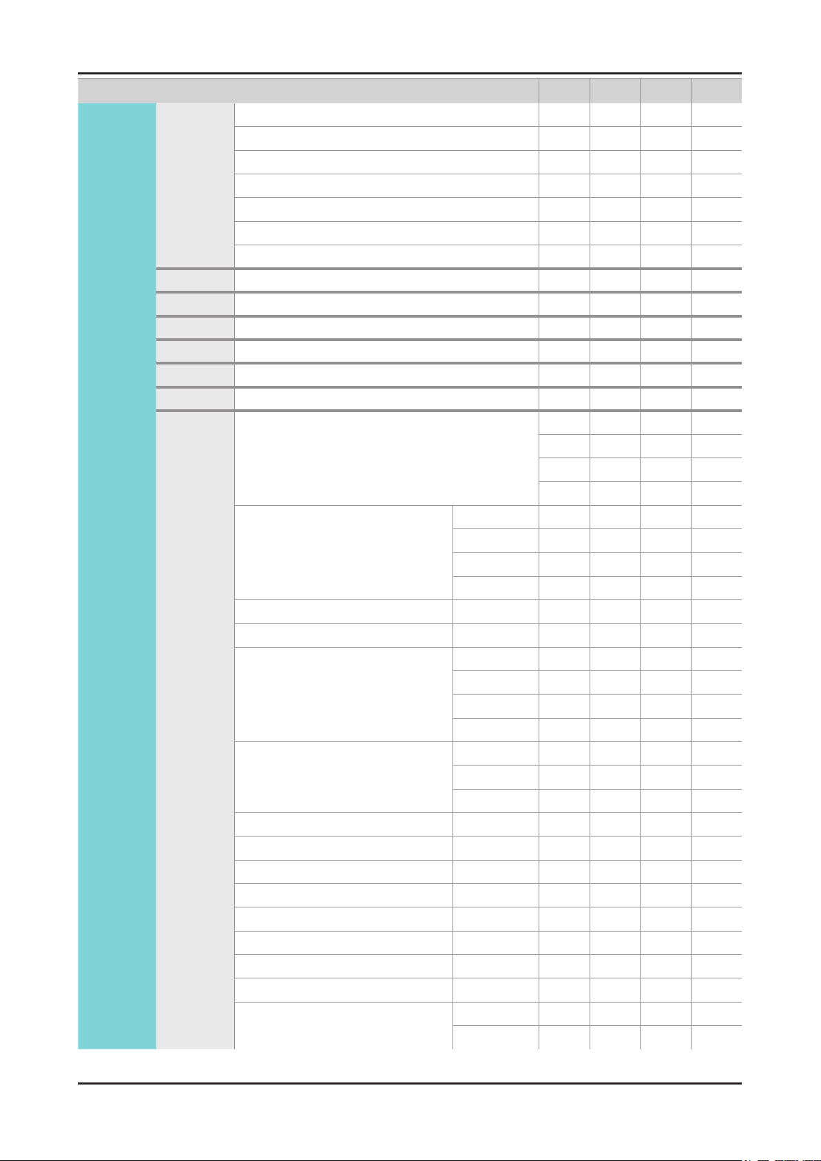
Control Item
PICTURE Mode Dynamic(Entertain) 0x0b 0x00 0x00 0x00
Standard 0x01
Movie 0x02
Natural
CAL-NIGHT 0x04
CAL-DAY 0x05
BD Wise 0x06
BackLight 0x01 0x00 (0~20)
Contrast 0x02 0x00
Brightness 0x03 0x00
Sharpness 0x04 0x00
Color 0x05 0x00
Tint G/R 0x06 0x00
Advanced
Settings
Black Tone 0x07 0x00 0x00
Cmd1 Cmd2 Cmd3 Value
0x03
(0~100)
(0~100)
(0~100)
(0~100)
(0~100)
0x01
0x02
0x03
Dynamic Contrast Off 0x01 0x00
Low 0x01
Medium 0x02
HIgh
Shadow Detail -2 ~ 2 0x02 (-2~2)
Gamma -3 ~ 3 0x03 (-3~3)
RGB Only Mode Off 0x05 0x00
Red 0x01
Green 0x02
Blue 0x03
Color Space Auto 0x06 0x00
Native 0x01
Custom 0x02
White Balance R-Offset(LCD) 0x07 (0~50)
White Balance
White Balance B-Offset(LCD) 0x09 (0~50)
G-Offset(LCD)
0x08 (0~50)
White Balance R-Gain(LCD) 0x0a (0~50)
White Balance G-Gain(LCD) 0x0b (0~50)
White Balance B-Gain(LCD) 0x0c (0~50)
White Balance Reset(LCD) 0x0d 0x00
Flesh Tone -15 ~ 15 0x0e
Edge Enhancement Off 0x0f 0x00
On 0x01
(-15~15)
Page 69
4-43
4. Troubleshooting
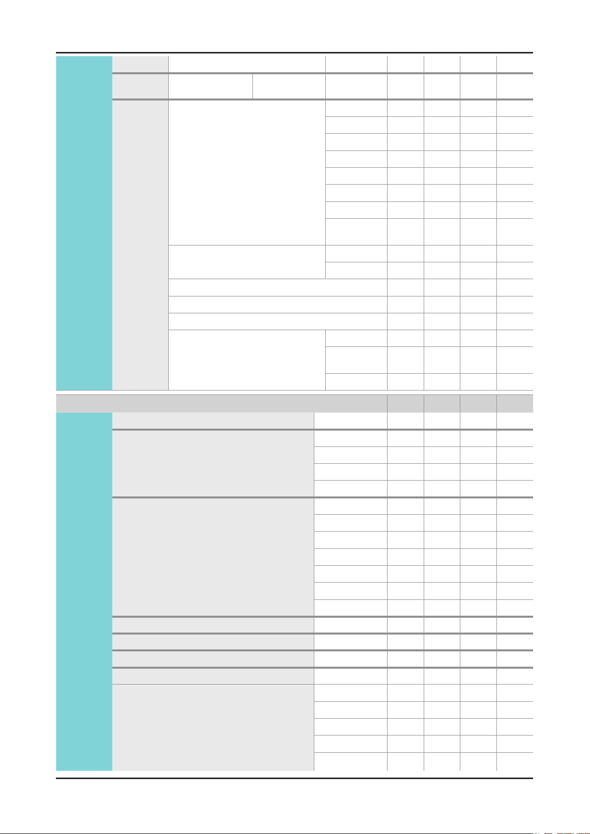
xvYCC Off 0x10 0x00
On 0x01
Motion Lighting Off 0x11 0x00
On 0x01
LED Motion Plus Off 0x07 0x00
On(Normal) 0x01
Cinema 0x02
Ticker 0x03
Picture
Option
Color Tone Cool 0x0a 0x00 0x00
Normal 0x01
Warm1 0x02
Warm2 0x03
Digital Noise Filter Off 0x02 0x00
Low 0x01
Medium 0x02
High 0x03
Auto 0x04
Auto
Visualization
MPEG Noise Filter Off 0x03 0x00
Low 0x01
Medium 0x02
High 0x03
Auto 0x04
HDMI Black Level Normal 0x04 0x00
Low 0x01
0x05
Screen
Adjustment
Film Mode Off 0x05 0x00
Auto1 0x01
Auto2 0x02
Auto Motion Plus Off 0x06 0x00
Clear 0x01
Standard 0x02
Smooth 0x03
Custom 0x04
Demo 0x05
Picture Size 16:9 0x0b 0x0a 0x01 0x00
Zoom1 0x01
Zoom2 0x02
Wide Fit
4:3 0x04
Screen Fit 0x05
Smart View I 0x06
0x03
Page 70
4-44
4. Troubleshooting
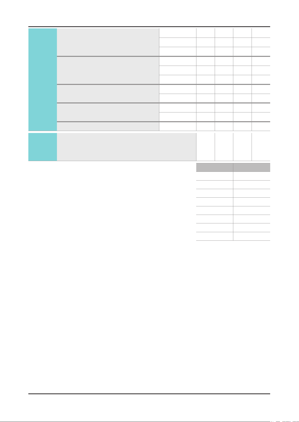
Smart View II 0x07
Reset
Picture
3D 3D Mode Off 0x0b 0x0c 0x00 0x00
Reset Picture
2D->3D 0x01
Side By Side 0x02
Top Bottom 0x03
Line By Line 0x04
Vertical Line 0x05
Checker BD 0x06
Frame
Sequence
3D 2D
3D View Point 0x02 (-5~5)
Depth 0x03 (1~10)
Picture Correction 0x04 0x00
3D Auto View Off 0x05 0x00
Off 0x01 0x00
On 0x01
Message
Notice
0x0b 0x0b 0x00 0x00
0x07
0x01
On 0x02
Control Item
Sound SRS TheaterSound(Genoa) Standard 0x0c 0x00 0x00 0x00
Sound Mode(X6) Music 0x01
Movie 0x02
Clear Voice 0x03
Amplify 0x04
Equalizer Balance 0x01 0x00 (0~20)
100hz 0x01 (0~20)
300hz 0x02 (0~20)
1khz 0x03 (0~20)
3khz 0x04 (0~20)
10khz 0x05 (0~20)
Reset 0x06 0x00
SRS TruSurround HD(Genoa) Off 0x02 0x00 0x00
Virtual Surrond(X6) On 0x01
SRS TruDialog(Genoa) Off 0x03 0x00 0x00
Cmd1 Cmd2 Cmd3 Value
Dialog Clarify(X6) On 0x01
Preferred Language English 0x04 0x00 0x00
Spanish 0x01
French 0x02
Korean 0x03
Japanese
0x04
Page 71
4-45
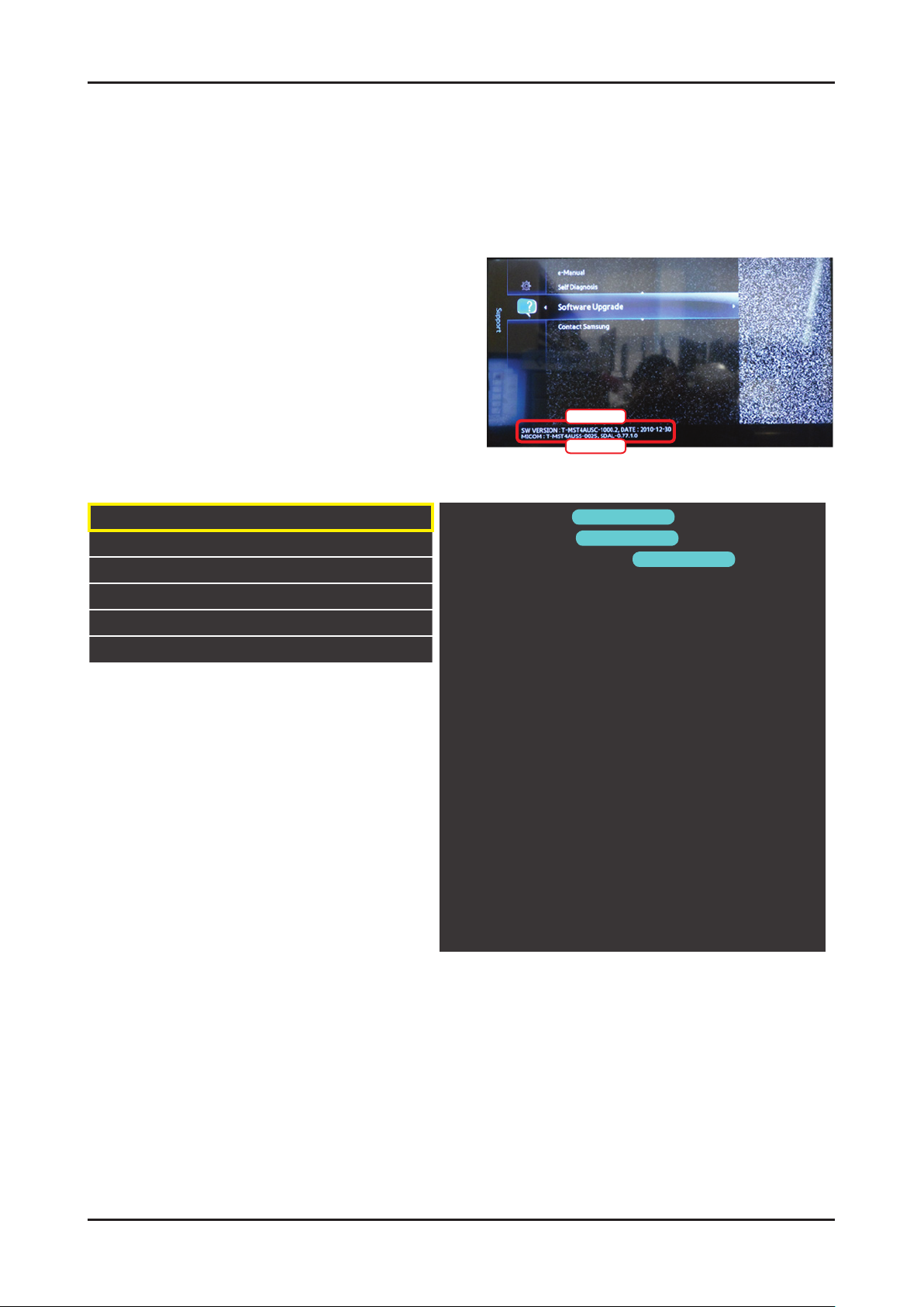
4. Troubleshooting
Multi-Track Sound Mono
Auto Volume Off
Speaker Select TV Speaker
Sound Select Main
Sound Reset Sound Reset
KEY Key Generation
Stereo
SAP
Normal
Night
External Speaker
Sub
0x05 0x00 0x00
0x06 0x00 0x00
0x07 0x00 0x00
0x08 0x00 0x00
0x09 0x00 0x00
0x0d 0x00 0x00
Key value Value
Up 96 (0x60)
0x01
0x02
0x01
0x02
0x01
0x01
refer
to the
table
of
below
Down 97 (0x61)
Left 101 (0x65)
Right 98 (0x62)
Menu 26 (0x1A)
Internet 147 (0x93)
Enter(OK) 104 (0x68)
EXIT 45 (0x2D)
Page 72
4-46
4. Troubleshooting
4-7. Software Upgrade
Software Upgrade can be performed by downloading the latest rmware from samsung.com to a USB memory device.
Current Version - the software already installed in the TV.
Note : Software is represented as ‘Year/Month/Day_Version’.
4-7-1. How to check the SW version
Use the main menu
Click the “menu” key in remote controler.1.
Select Support menu.2.
Locate the menu cursor “Software Upgrade” menu.3.
Click the “info” key.4.
Check the Main SW and Micom version.5.
Main SW
Sub Micom
Use the factory mode
Access the factory mode
Option
Control
SVC
Expert
ADC/WB
Advanced
T-MST5DCNC-XXX
T-MST5DCNC-XXX
main micom
sub micom
E-Manual : X6DVBHKA-000X
Version
Version
e-manual
Version
EDID SUCCESS
HDCP : SUCCESS
CALIB : AV / COM / PC / HDMI /
Option : XXXX XXXX XXXX X
SDAL-XXX
RFS : Mstar-X6 XXXX
KERNERL MODULE VERSION : "XXXXX_XX"
20XX-XX-XX
TYPE : XXXXXX
MAC Not Available
FACTORY DATA VER : XXX
EERC VERSION : XXX
DTP-AP-COMP-624
DTP-BP-HAl-0117
DTP-BP-0611
DATE OF PURCHASE : XX/XX/XX
Page 73
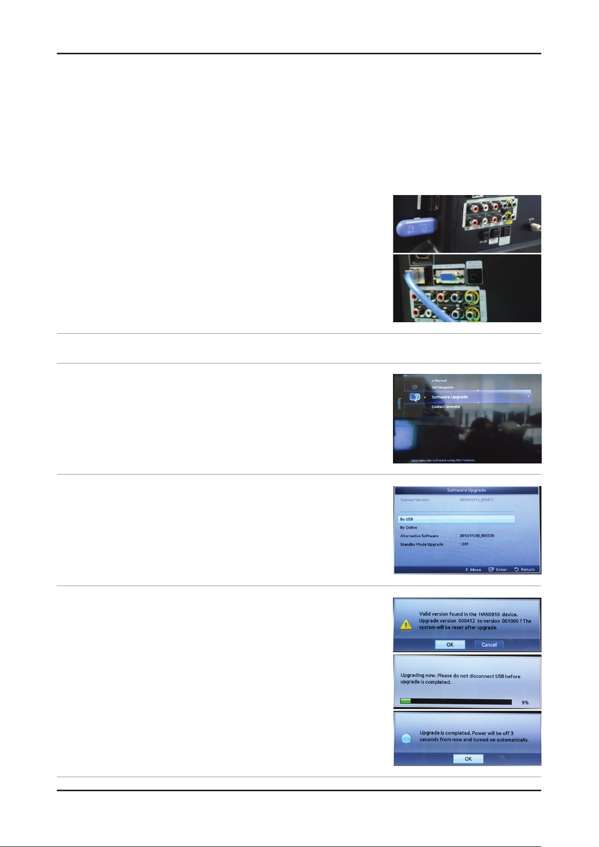
4-47
4. Troubleshooting
4-7-2. How to Upgade SW and Micom
Insert a USB drive containing the rmware upgrade downloaded from samsung.com into the TV.
Please be careful to not disconnect the power or remove the USB drive while upgrades are being applied. The TV will
turn off and turn on automatically after completing the rmware upgrade. Please check the rmware version after the
upgrades are complete (the new version will have a higher number than the older version). When software is upgraded,
video and audio settings you have When software is upgraded, video and audio settings you have you write down your
settings so that you can easily reset them after the upgrade.
Main SW upgrade
Store the sw program named “T-MST5IBRC” in USB memory stick.1.
Connect the USB. -
Connect TV and online line. -
Click the2. MENU key in remote controler.
Select 3. Support menu.
Locate the menu cursor - Software Upgrade menu.
Click the 4. ENTER key.
You can upgrade - By USB or Online.
Click the 5. ENTER key.
Wait for upgrade complete and check the SW version. -
Page 74
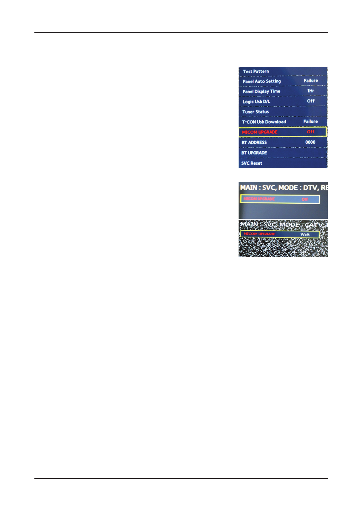
4-48
4. Troubleshooting
Sub micom upgrade
You can upgarde sub micom in factory mode without DDC program.
But it take long time about 5 minuites.
Access the fatory mode.1.
Select the - SVC menu and locate the cursor MICOM UPGRADE menu.
Click the 2. ENTER key.
Click the - right key.
Wait for upgrade complete and check the Micom version. -
Page 75
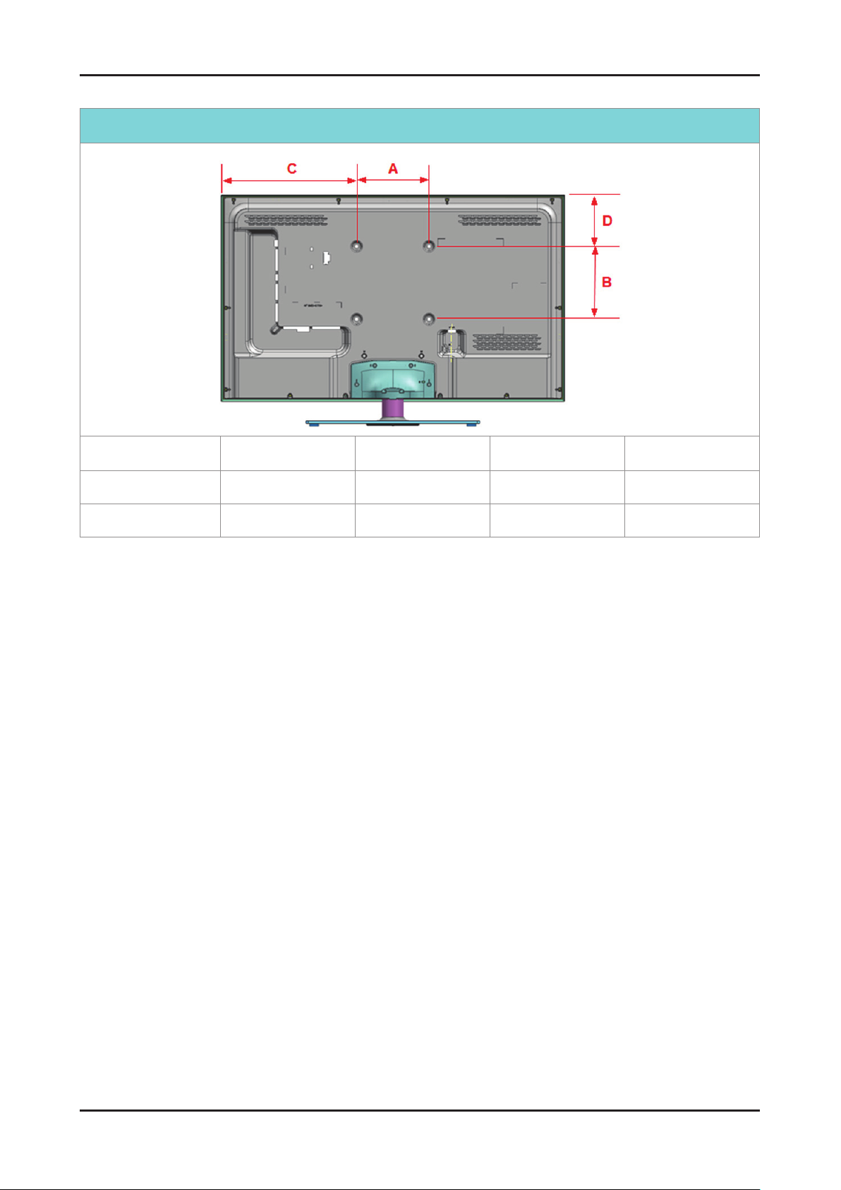
4-49
4. Troubleshooting
4-8. Rear Cover Dimension
UD5500 A B C D
Cover-Rear Area
32"
40"
200 200 284.2 100.9
200 200 377.9 144.2
Page 76
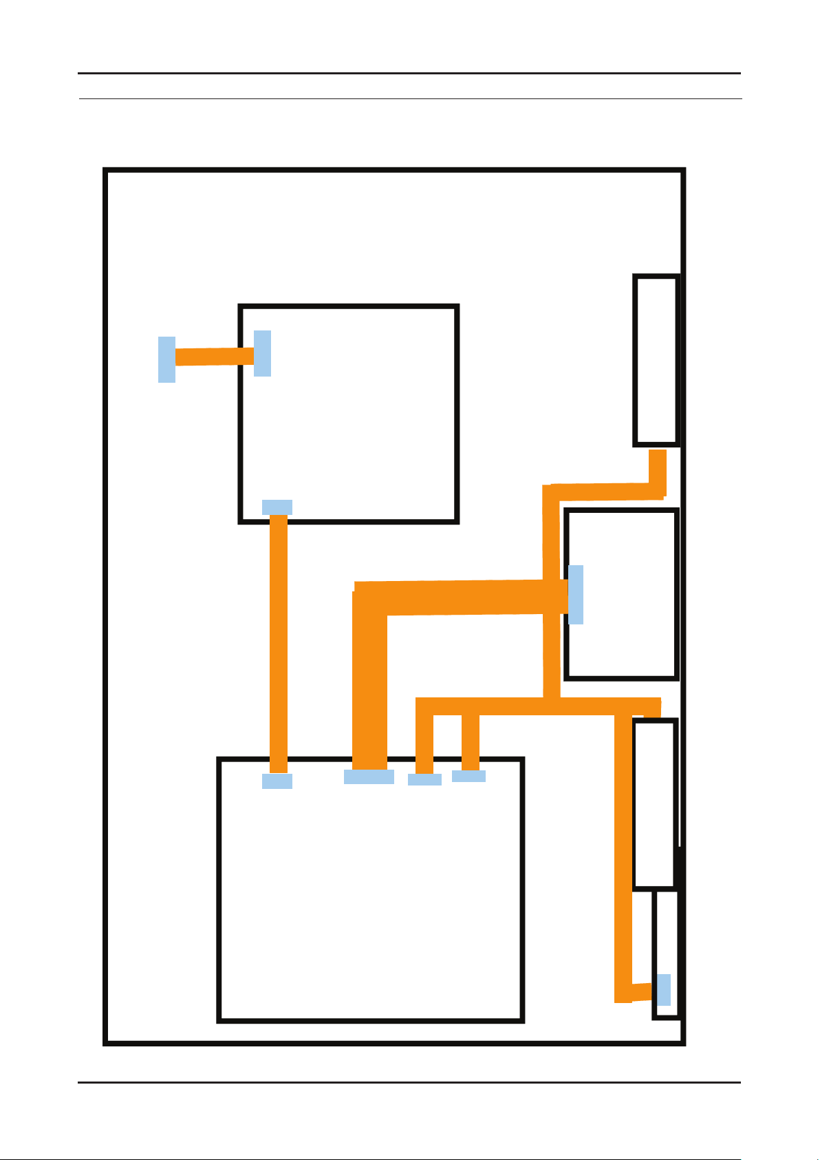
5. Wiring Diagram
T-CON
Main Board
IP Board
PANEL
CN201
CN1601_FHD
Speaker
CNI802
CN801
Speaker
FUNCTION& IR
CN1201
CN302
CN1
5-1. Wiring Diagram
5. Wiring Diagram
5-1
Page 77
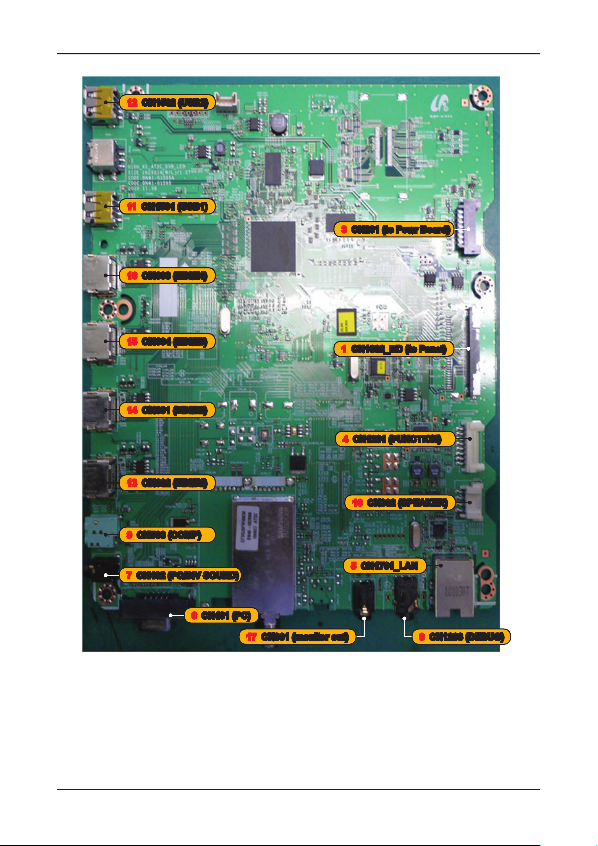
5-2
5. Wiring Diagram
5-2. Position of Connector
12 CN1502 (USB2)
11 CN1501 (USB1)
16 CN603 (HDMI4)
3 CN201 (to Powr Board)
15 CN604 (HDMI3)
14 CN601 (HDMI2)
13 CN602 (HDMI1)
9 CN503 (COMP)
7 CN402 (PC/DIV SOUND)
6 CN401 (PC)
1 CN1602_HD (to Panel)
4 CN1201 (FUNCTION)
10 CN302 (SPEAKER)
5 CN1701_LAN
17 CN301 (monitor out)
8 CN1203 (DEBUG)
Page 78
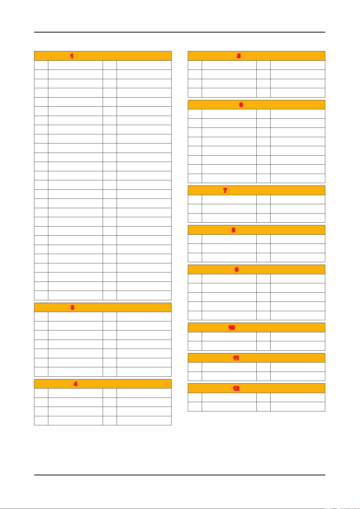
5-2-1. Connector
5-3
5. Wiring Diagram
1 CN1601_FHD (to Panel)
1 NC 27 EVEN[0]-
2 NC 28 GND
3 NC 29 ODD[4]+
4 NC 30 ODD[4]-
5 NC 31 ODD[3]+
6 NC 32 ODD[3]-
7 FORMAT 33 GND
8 SDA_Panel 34 ODDCLK+
9 TCON_WP 35 ODDCLK-
10 NC 36 GND
11 SDA_Panel 37 ODD[2]+
12 SCL_Panel 38 ODD[2]-
13 GND 39 ODD[1]+
14 EVEN[4]+ 40 ODD[1]-
15 EVEN[4]- 41 ODD[0]+
16 EVEN[3]+ 42 ODD[0]-
17 EVEN[3]- 43 GND
18 GND 44 GND
19 EVENCLK+ 45 GND
20 EVENCLK- 46 NC
21 GND 47 Panel_VCC
22 EVEN[2]+ 48 Panel_VCC
23 EVEN[2]- 49 Panel_VCC
24 EVEN[1]+ 50 Panel_VCC
25 EVEN[1]- 51 Panel_VCC
26 EVEN[0]+
3 CN201 (to Powr Board)
1 B5V 8 GND
2 SW_POWER 9 B12VS
3 B5V 10 SW_INVERTER
4 A5V 11 B13V
5 GND 12 NC
6 GND 13 B13V
7 B12VS 14 PWM_DIMM
4 CN1201 (FUNCTION)
1 IR 5 MSDA
2 GND 6 FUNC_INTR
3 A3.3V 7 LED_STB
4 MSCL 8 NC
5 CN1701_LAN
1 LAN_TX- 5 LAN_VCC
2 GND 6 LAN_RX-
3 LAN_TX+ 7 NC
4 LAN_RX+ 8 GND
6 CN401 (PC)
1 PC_RED 9 PC_5V
2 PC_GREEN 10 IDENT_PC
3 PC_BLUE 11 R_FANET
4 T_FANET 12 SDA_DOWN
5 GND 13 PC_HS
6 GND 14 PC_VS
7 GND 15 SCL_DOWN
8 GND
7 CN402 (PC/DIV SOUND)
1 GND 4 NC
2 PC_SR_IN 5 NC
3 PC_SL_IN 6 NC
8 CN1203 (DEBUG)
1 GND 4 DEBUG_TX
2 DEBUG_RX 5 DEBUG_TX
3 DEBUG_TX 6 GND
9 CN503 (COMP)
1 GND 6 GND
2 COMP1_Y 7 COMP1_ID
3 COMP1_PB 8 COMP1_L
4 AV_ID 9 COMP1_R
5 COMP1_PR
10 CN302 (SPEAKER)
1 R+ 3 L+
2 R- 4 L-
11 CN1501 (USB1)
1 USB_VCC 3 USB_DP
2 USB_DM 4 GND
12 CN1502 (USB2)
1 USB_VCC 3 USB_DP
2 USB_DM 4 GND
Page 79
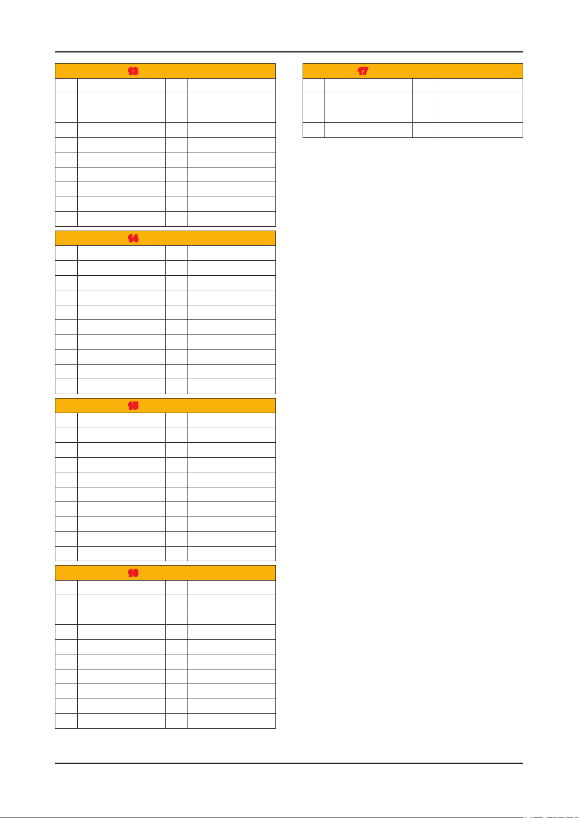
5-4
5. Wiring Diagram
13 CN602 (HDMI1)
1 HDMI1_RX2+ 11 GND
2 GND 12 HDMI1_RXCLK-
3 HDMI1_RX2- 13 HDMI_CEC
4 HDMI1_RX1+ 14 GND
5 GND 15 SCL
6 HDMI1_RX1- 16 SDA
7 HDMI1_RX0+ 17 GND
8 GND 18 5V
9 HDMI1_RX0- 19 HPD
10 HDMI1_RXCLK+
14 CN601 (HDMI2)
1 HDMI2_RX2+ 11 GND
2 GND 12 HDMI2_RXCLK-
3 HDMI2_RX2- 13 HDMI_CEC
4 HDMI2_RX1+ 14 GND
5 GND 15 SCL
6 HDMI2_RX1- 16 SDA
7 HDMI2_RX0+ 17 GND
8 GND 18 5V
9 HDMI2_RX0- 19 HPD
10 HDMI2_RXCLK+
17 CN301 (MONITOR OUT)
1 GND 5 NC
2 OUT_R 6 GND
3 OUT_R 7 NC
4 GND
15 CN604 (HDMI3)
1 HDMI3_RX2+ 11 GND
2 GND 12 HDMI3_RXCLK-
3 HDMI3_RX2- 13 HDMI_CEC
4 HDMI3_RX1+ 14 GND
5 GND 15 SCL
6 HDMI3_RX1- 16 SDA
7 HDMI3_RX0+ 17 GND
8 GND 18 5V
9 HDMI3_RX0- 19 HPD
10 HDMI3_RXCLK+
16 CN603 (HDMI4)
1 HDMI4_RX2+ 11 GND
2 GND 12 HDMI4_RXCLK-
3 HDMI4_RX2- 13 HDMI_CEC
4 HDMI4_RX1+ 14 GND
5 GND 15 SCL
6 HDMI4_RX1- 16 SDA
7 HDMI4_RX0+ 17 GND
8 GND 18 5V
9 HDMI4_RX0- 19 HPD
10 HDMI4_RXCLK+
Page 80
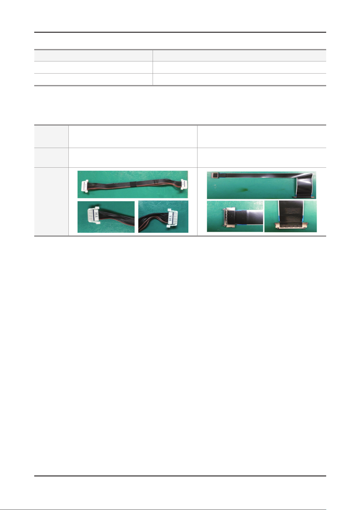
5-3. Connector Functions
5-5
5. Wiring Diagram
Connector Functions
CN201 IP CN801
CN1601_FHD/CN1602_HD T-CON CNF1
5-4. Cables
Use
Code
Photo
LEAD
(Main-IP 14P)
32" : BN39-01455D
40" : BN39-01481A
Supply main power and dimming signal from IP board to Main Board.
The LVDS signal transfered from Main Board to Panel .
LVDS
(Main - TCON)
32" : BN96-17116E
40" : BN96-17116F
 Loading...