

Page 1
LED/LCD-TV
Chassis : U57E
Model : UE40D500*BW
UE26D400*BW
UE32D400*BW
Chassis : U57F
Model : UE22D500*BW
UE19D400*BW
SERVICE
TFT-LED/LCD TV Contents
Chassis : U56G
Model : LE32D400E1W
LE32D40*E2W
LE40D50*F7W
Manual
UE32D400*BW
1. Precautions
2. Product specications
3. Disassembly and Reassembly
4. Troubleshooting
5. Wiring Diagram
LE32D400E1W
Page 2

Contents
1. Precautions .............................................................................................................. 1-1
1-1. Safety Precautions ......................................................................................................... 1-1
1-2. Servicing Precautions ..................................................................................................... 1-2
1-3. Electrostatically Sensitive Devices (ESD) Precautions .................................................. 1-2
1-4. Installation Precautions .................................................................................................. 1-3
2. Product specications ............................................................................................ 2-1
2-1. Feature & Specications ................................................................................................. 2-1
2-2. Detail Factory Option ...................................................................................................... 2-9
2-3. Accessories .................................................................................................................. 2-10
2-4. New Features explanation ............................................................................................ 2-11
3. Disassembly and Reassembly ............................................................................... 3-1
3-1. Disassembly and Reassembly ....................................................................................... 3-1
4. Troubleshooting ...................................................................................................... 4-1
4-1. Troubleshooting .............................................................................................................. 4-1
4-2. Alignments and Adjustments ........................................................................................ 4-36
4-3. Factory Mode Adjustments ........................................................................................... 4-37
4-4. White Balance - Calibration .......................................................................................... 4-44
4-5. White Ratio (Balance) Adjustment ................................................................................ 4-45
4-6. Servicing Information .................................................................................................... 4-46
4-7. How To Upgrade Sub Micom ........................................................................................ 4-47
4-8. Mechanical diagram ..................................................................................................... 4-48
4-9. PCB diagram ................................................................................................................ 4-49
5. Wiring Diagram ........................................................................................................ 5-1
5-1. Wiring Diagram ............................................................................................................... 5-1
5-2. Connector ....................................................................................................................... 5-3
5-3. Connector Functions ...................................................................................................... 5-6
5-4. Cables ............................................................................................................................ 5-6
Page 3
This Service Manual is a property of Samsung Electronics Co.,Ltd.
Any unauthorized use of Manual can be punished under applicable
International and/or domestic law.
© 2011 Samsung Electronics Co.,Ltd.
All rights reserved.
Printed in Korea
Page 4
1. Precautions
1. Precautions
1-1. Safety Precautions
Follow these safety, servicing and ESD precautions to prevent damage and to protect against potential hazards such as
electrical shock.
1-1-1. Warnings
For continued safety, do not attempt to modify the circuit board.1.
Disconnect the AC power and DC power jack before servicing.2.
1-1-2. Servicing the LED/LCD TV
When servicing the LED/LCD TV, Disconnect the AC line cord from the AC outlet.1.
It is essential that service technicians have an accurate voltage meter available at all times. 2.
Check the calibration of this meter periodically.
1-1-3. Fire and Shock Hazard
Before returning the LED/LCD TV to the user, perform the following safety checks:
Inspect each lead dress to make certain that the leads are not pinched or that hardware is not lodged between the 1.
chassis and other metal parts in the LED/LCD TV.
Inspect all protective devices such as nonmetallic control knobs, insulating materials, cabinet backs, adjustment and 2.
compartment covers or shields, isolation resistorcapacitor networks, mechanical insulators, etc.
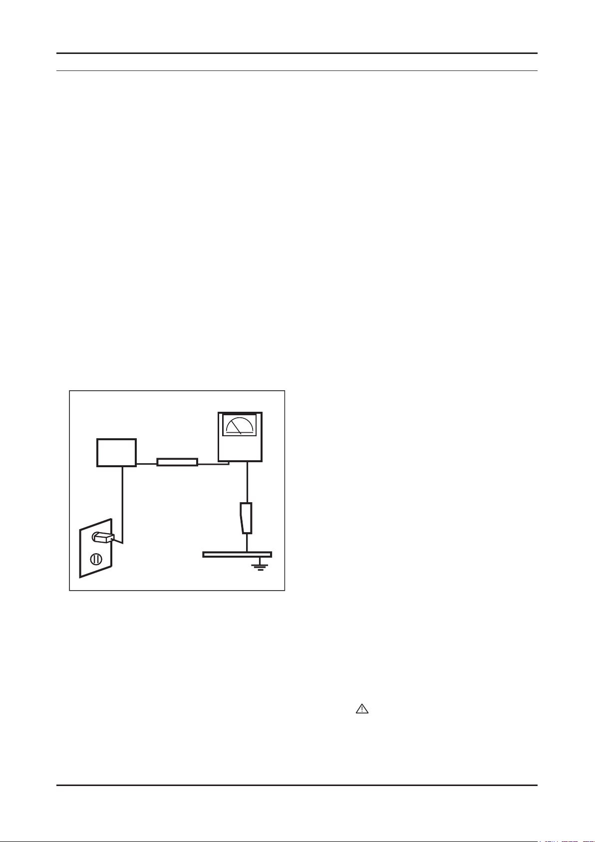
Leakage Current Hot Check (Figure 1-1): 3.
WARNING : Do not use an isolation transformer during this test.
Use a leakage current tester or a metering system that complies with American National Standards Institute (ANSI
C101.1, Leakage Current for Appliances), and Underwriters Laboratories (UL Publication UL1410, 59.7).
(READING SHOULD)
NOT BE ABOVE 0.5mA
DEVICE
UNDER
TEST
2-WIRE CORD
*ALSO TEST WITH
PLUG REVERSED
(USING AC ADAPTER
PLUG AS REQUIRED)
TEST ALL
EXPOSED METAL
SURFACES
LEAKAGE
CURRENT
TESTER
EARTH
GROUND
Figure 1-1. Leakage Current Test Circuit
With the unit completely reassembled, plug the AC line cord directly into a 120V AC outlet. With the unit’s AC switch 4.
rst in the ON position and then OFF, measure the current between a known earth ground (metal water pipe, conduit,
etc.) and all exposed metal parts, including: metal cabinets, screwheads and control shafts.
The current measured should not exceed 0.5 milliamp.
Reverse the power-plug prongs in the AC outlet and repeat the test.
1-1-4. Product Safety Notices
Some electrical and mechanical parts have special safetyrelated characteristics which are often not evident from visual
inspection. The protection they give may not be obtained by replacing them with components rated for higher voltage,
wattage, etc. Parts that have special safety characteristics are identied by on schematics and parts lists. A substitute
replacement that does not have the same safety characteristics as the recommended replacement part might create
shock, re and/or other hazards. Product safety is under review continuously and new instructions are issued whenever
appropriate.
1-1
Page 5

1-2
1. Precautions
1-2. Servicing Precautions
WARNING: An electrolytic capacitor installed with the wrong polarity might explode.
Caution: Before servicing units covered by this service manual, read and follow the Safety Precautions section of
this manual.
Note: If unforeseen circumstances create conict between the following servicing precautions and any of the
safety precautions, always follow the safety precautions.
1-2-1 General Servicing Precautions
Always unplug the unit’s AC power cord from the AC power source and disconnect the DC Power Jack before 1.
attempting to:
(a) remove or reinstall any component or assembly, (b) disconnect PCB plugs or connectors, (c) connect a test
component in parallel with an electrolytic capacitor.
Some components are raised above the printed circuit board for safety. An insulation tube or tape is sometimes 2.
used. The internal wiring is sometimes clamped to prevent contact with thermally hot components. Reinstall all such
elements to their original position.
After servicing, always check that the screws, components and wiring have been correctly reinstalled. Make sure that 3.
the area around the serviced part has not been damaged.
Check the insulation between the blades of the AC plug and accessible conductive parts (examples: metal panels, 4.
input terminals and earphone jacks).
Insulation Checking Procedure: Disconnect the power cord from the AC source and turn the power switch ON. 5.
Connect an insulation resistance meter (500 V) to theblades of the AC plug.
The insulation resistance between each blade of the AC plug and accessible conductive parts (see above) should be
greater than 1 megohm.
Always connect a test instrument’s ground lead to the instrument chassis ground before connecting the positive lead; 6.
always remove the instrument’s ground lead last.
1-3. Electrostatically Sensitive Devices (ESD) Precautions
Some semiconductor (solid state) devices can be easily damaged by static electricity. Such components are commonly
called Electrostatically Sensitive Devices (ESD). Examples of typical ESD are integrated circuits and some eld-effect
transistors. The following techniques will reduce the incidence of component damage caused by static electricity.
Immediately before handling any semiconductor components or assemblies, drain the electrostatic charge from your 1.
body by touching a known earth ground. Alternatively, wear a discharging wrist-strap device. To avoid a shock hazard,
be sure to remove the wrist strap before applying power to the LED/LCD TV.
After removing an ESD-equipped assembly, place it on a conductive surface such as aluminum foil to prevent 2.
accumulation of an electrostatic charge.
Do not use freon-propelled chemicals. These can generate electrical charges sufcient to damage ESDs.3.
Use only a grounded-tip soldering iron to solder or desolder ESDs.4.
Use only an anti-static solder removal device. Some solder removal devices not classied as “anti-static” can generate 5.
electrical charges sufcient to damage ESDs.
Do not remove a replacement ESD from its protective package until you are ready to install it. Most replacement ESDs 6.
are packaged with leads that are electrically shorted together by conductive foam, aluminum foil or other conductive
materials.
Immediately before removing the protective material from the leads of a replacement ESD, touch the protective 7.
material to the chassis or circuit assembly into which the device will be installed.
Caution: Be sure no power is applied to the chassis or circuit and observe all other safety precautions.
Minimize body motions when handling unpackaged replacement ESDs. Motions such as brushing clothes together, 8.
or lifting your foot from a carpeted oor can generate enough static electricity to damage an ESD.
Page 6

1-3
1. Precautions
1-4. Installation Precautions
For safety reasons, more than a people are required for carrying the product.1.
Keep the power cord away from any heat emitting devices, as a melted covering may cause re or electric shock.2.
Do not place the product in areas with poor ventilation such as a bookshelf or closet. The increased internal 3.
temperature may cause re.
Bend the external antenna cable when connecting it to the product. This is a measure to protect it from being exposed 4.
to moisture. Otherwise, it may cause a re or electric shock.
Make sure to turn the power off and unplug the power cord from the outlet before repositioning the product. Also check 5.
the antenna cable or the external connectors if they are fully unplugged. Damage to the cord may cause re or electric
shock.
Keep the antenna far away from any high-voltage cables and install it rmly. Contact with the highvoltage cable or the 6.
antenna falling over may cause re or electric shock.
When installing the product, leave enough space (0.4m) between the product and the wall for ventilation purposes. 7.
A rise in temperature within the product may cause re.
Page 7
2. Product specications
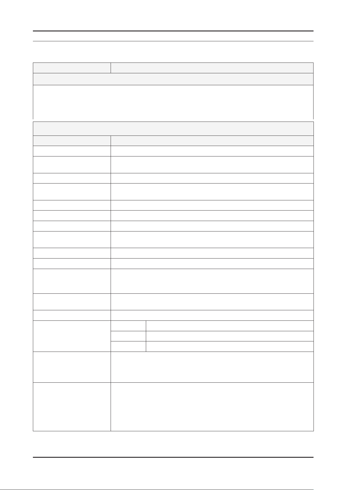
2-1. Feature & Specications
Model UE22D500*BW
Feature
DTV/ATV, 2-HDMI, 1-SCART, 1-USB2.0 ሪ
Brightness : 480 cd/m ሪ
High Contrast Ratio : 6,000 :1 ሪ
Response Time : 8.5 ms ሪ
Item Description
LCD Panel 22 inch FHD
Scanning Frequency Horizontal : 50 kHz ~ 75 kHz (Automatic)
Display Colors 16.7M color
Maximum resolution Horizontal : 1920 Pixels
2
Specications
Vertical : 47 Hz ~ 63 Hz (Automatic)
Vertical : 1080 Pixels
2. Product specications
Input Signal Analog 0.7 Vp-p ± 5% positive at 75Ω , internally terminated
Input Sync Signal H/V Separate, TTL, P. or N.
Maximum Pixel Clock rate 80 MHz
Active Display
Horizontal/Vertical
AC power voltage & Frequency AC 110 V ~ 220 V, 60 Hz
Power Consumption Under 110 W (Under 0.3 W, Stand by)
Dimensions
Set (W x D x H)
Weight 3.5 kg_with stand
Stand Weight 0.1 kg
TV System Tuning Frequency Synthesize (Refer to detailed Frequency Table)
Environmental Considerations Operating Temperature : 50˚F ~ 104˚F (10˚C ~ 40˚C)
476.64(H) x 268.11(V) mm
515.8 x 124 x 350.0 mm_with stand
515.8 x 39.9 x 315.6 mm_without stand
3.4 kg_without stand
System DVB-T/C, PAL, SECAM, NT4.43
Sound BG, DK, L/L’, NICAM, MPEG1, DD, DD+, HE-AAC
Operating Humidity : 10% ~ 80%, non-condensing
Storage temperature : -13˚F ~ 113˚F (-25˚C ~ 45˚C)
Storage Humidity : 5% ~ 95%, non-condensing
Audio Spec. - MAX Internal Audio Output Power : Each 3 W (Left/Right)
- BASS Control Range : -8 dB ~ + 8dB
- TREBLE Control Range : -8 dB ~ +8 dB
- Headphone Out : 10 mW MAX
- Output Frequency : RF : 80 Hz ~ 15 kHz
AV/Componet/HDMI : 80 Hz ~ 20 kHz
2-1
Page 8

2-2
2. Product specications
Model UE40D500*BW
Feature
DTV/ATV, 2-HDMI, 1-SCART, 1-USB2.0 ሪ
Brightness : 480 cd/m ሪ
2
High Contrast Ratio : 6,000 :1 ሪ
Response Time : 8.5 ms ሪ
Specications
Item Description
LCD Panel 40 inch FHD
Scanning Frequency Horizontal : 50 kHz ~ 75 kHz (Automatic)
Vertical : 47 Hz ~ 63 Hz (Automatic)
Display Colors 16.7M color
Maximum resolution Horizontal : 1920 Pixels
Vertical : 1080 Pixels
Input Signal Analog 0.7 Vp-p ± 5% positive at 75Ω , internally terminated
Input Sync Signal H/V Separate, TTL, P. or N.
Maximum Pixel Clock rate 80 MHz
Active Display
Horizontal/Vertical
885.6(H) x 498.15(V) mm
AC power voltage & Frequency AC 110 V ~ 220 V, 60 Hz
Power Consumption Under 110 W (Under 0.3 W, Stand by)
Dimensions
Set (W x D x H)
943.8 x 219.4 x 603.5 mm_with stand
943.8 x 51.0 x 561.4 mm_without stand
Weight 11 kg_with stand
10.6 kg_without stand
Stand Weight 0.4 kg
TV System Tuning Frequency Synthesize (Refer to detailed Frequency Table)
System DVB-T/C, PAL, SECAM, NT4.43
Sound BG, DK, L/L’, NICAM, MPEG1, DD, DD+, HE-AAC
Environmental Considerations Operating Temperature : 50˚F ~ 104˚F (10˚C ~ 40˚C)
Operating Humidity : 10% ~ 80%, non-condensing
Storage temperature : -13˚F ~ 113˚F (-25˚C ~ 45˚C)
Storage Humidity : 5% ~ 95%, non-condensing
Audio Spec. - MAX Internal Audio Output Power : Each 3 W (Left/Right)
- BASS Control Range : -8 dB ~ + 8dB
- TREBLE Control Range : -8 dB ~ +8 dB
- Headphone Out : 10 mW MAX
- Output Frequency : RF : 80 Hz ~ 15 kHz
AV/Componet/HDMI : 80 Hz ~ 20 kHz
Page 9

2-3
2. Product specications
Model UE19D400*BW
Feature
DTV/ATV, 2-HDMI, 1-SCART, 1-USB2.0 ሪ
Brightness : 480 cd/m ሪ
2
High Contrast Ratio : 6,000 :1 ሪ
Response Time : 8.5 ms ሪ
Specications
Item Description
LCD Panel 19 inch HD
Scanning Frequency Horizontal : 50 kHz ~ 75 kHz (Automatic)
Vertical : 47 Hz ~ 63 Hz (Automatic)
Display Colors 16.7M color
Maximum resolution Horizontal : 1920 Pixels
Vertical : 1080 Pixels
Input Signal Analog 0.7 Vp-p ± 5% positive at 75Ω , internally terminated
Input Sync Signal H/V Separate, TTL, P. or N.
Maximum Pixel Clock rate 80 MHz
Active Display
Horizontal/Vertical
409.8(H) x 230.4(V) mm
AC power voltage & Frequency AC 110 V ~ 220 V, 60 Hz
Power Consumption Under 110 W (Under 0.3 W, Stand by)
Dimensions
Set (W x D x H)
447.2 x 124 x 312.4 mm_with stand
447.2 x 39.9 x 277.8 mm_without stand
Weight 2.9 kg_with stand
2.8 kg_without stand
Stand Weight 0.1 kg
TV System Tuning Frequency Synthesize (Refer to detailed Frequency Table)
System DVB-T/C, PAL, SECAM, NT4.43
Sound BG, DK, L/L’, NICAM, MPEG1, DD, DD+, HE-AAC
Environmental Considerations Operating Temperature : 50˚F ~ 104˚F (10˚C ~ 40˚C)
Operating Humidity : 10% ~ 80%, non-condensing
Storage temperature : -13˚F ~ 113˚F (-25˚C ~ 45˚C)
Storage Humidity : 5% ~ 95%, non-condensing
Audio Spec. - MAX Internal Audio Output Power : Each 3 W (Left/Right)
- BASS Control Range : -8 dB ~ + 8dB
- TREBLE Control Range : -8 dB ~ +8 dB
- Headphone Out : 10 mW MAX
- Output Frequency : RF : 80 Hz ~ 15 kHz
AV/Componet/HDMI : 80 Hz ~ 20 kHz
Page 10

2-4
2. Product specications
Model UE26D400*BW
Feature
DTV/ATV, 2-HDMI, 1-SCART, 1-USB2.0 ሪ
Brightness : 480 cd/m ሪ
2
High Contrast Ratio : 6,000 :1 ሪ
Response Time : 8.5 ms ሪ
Specications
Item Description
LCD Panel 26 inch HD
Scanning Frequency Horizontal : 50 kHz ~ 75 kHz (Automatic)
Vertical : 47 Hz ~ 63 Hz (Automatic)
Display Colors 16.7M color
Maximum resolution Horizontal : 1920 Pixels
Vertical : 1080 Pixels
Input Signal Analog 0.7 Vp-p ± 5% positive at 75Ω , internally terminated
Input Sync Signal H/V Separate, TTL, P. or N.
Maximum Pixel Clock rate 80 MHz
Active Display
Horizontal/Vertical
575.679(H) x 323.721(V) mm
AC power voltage & Frequency AC 110 V ~ 220 V, 60 Hz
Power Consumption Under 110 W (Under 0.3 W, Stand by)
Dimensions
Set (W x D x H)
624.0 x 169.4 x 418.3 mm_with stand
624.0 x 45.1 x 377.2 mm_without stand
Weight 4.4 kg_with stand
4.1 kg_without stand
Stand Weight 0.3 kg
TV System Tuning Frequency Synthesize (Refer to detailed Frequency Table)
System DVB-T/C, PAL, SECAM, NT4.43
Sound BG, DK, L/L’, NICAM, MPEG1, DD, DD+, HE-AAC
Environmental Considerations Operating Temperature : 50˚F ~ 104˚F (10˚C ~ 40˚C)
Operating Humidity : 10% ~ 80%, non-condensing
Storage temperature : -13˚F ~ 113˚F (-25˚C ~ 45˚C)
Storage Humidity : 5% ~ 95%, non-condensing
Audio Spec. - MAX Internal Audio Output Power : Each 3 W (Left/Right)
- BASS Control Range : -8 dB ~ + 8dB
- TREBLE Control Range : -8 dB ~ +8 dB
- Headphone Out : 10 mW MAX
- Output Frequency : RF : 80 Hz ~ 15 kHz
AV/Componet/HDMI : 80 Hz ~ 20 kHz
Page 11
2-5
2. Product specications
Model UE32D400*BW
Feature
DTV/ATV, 2-HDMI, 1-SCART, 1-USB2.0 ሪ
Brightness : 480 cd/m ሪ
2
High Contrast Ratio : 6,000 :1 ሪ
Response Time : 8.5 ms ሪ
Specications
Item Description
LCD Panel 32 inch HD
Scanning Frequency Horizontal : 50 kHz ~ 75 kHz (Automatic)
Vertical : 47 Hz ~ 63 Hz (Automatic)
Display Colors 16.7M color
Maximum resolution Horizontal : 1920 Pixels
Vertical : 1080 Pixels
Input Signal Analog 0.7 Vp-p ± 5% positive at 75Ω , internally terminated
Input Sync Signal H/V Separate, TTL, P. or N.
Maximum Pixel Clock rate 80 MHz
Active Display
Horizontal/Vertical
679.6845(H) x 392.256(V) mm
AC power voltage & Frequency AC 110 V ~ 220 V, 60 Hz
Power Consumption Under 110 W (Under 0.3 W, Stand by)
Dimensions
Set (W x D x H)
756.4 x 182.4 x 498.1 mm_with stand
756.4 x 47.8 x 454.0 mm_without stand
Weight 7.2 kg_with stand
6.3 kg_without stand
Stand Weight 0.9 kg
TV System Tuning Frequency Synthesize (Refer to detailed Frequency Table)
System DVB-T/C, PAL, SECAM, NT4.43
Sound BG, DK, L/L’, NICAM, MPEG1, DD, DD+, HE-AAC
Environmental Considerations Operating Temperature : 50˚F ~ 104˚F (10˚C ~ 40˚C)
Operating Humidity : 10% ~ 80%, non-condensing
Storage temperature : -13˚F ~ 113˚F (-25˚C ~ 45˚C)
Storage Humidity : 5% ~ 95%, non-condensing
Audio Spec. - MAX Internal Audio Output Power : Each 3 W (Left/Right)
- BASS Control Range : -8 dB ~ + 8dB
- TREBLE Control Range : -8 dB ~ +8 dB
- Headphone Out : 10 mW MAX
- Output Frequency : RF : 80 Hz ~ 15 kHz
AV/Componet/HDMI : 80 Hz ~ 20 kHz
Page 12

2-6
2. Product specications
Model LE40D50*F7W
Feature
DTV/ATV, 2-HDMI, 1-SCART, 1-USB2.0 ሪ
Brightness : 480 cd/m ሪ
2
High Contrast Ratio : 6,000 :1 ሪ
Response Time : 8.5 ms ሪ
Specications
Item Description
LCD Panel 40 inch HD
Scanning Frequency Horizontal : 50 kHz ~ 75 kHz (Automatic)
Vertical : 47 Hz ~ 63 Hz (Automatic)
Display Colors 16.7M color
Maximum resolution Horizontal : 1920 Pixels
Vertical : 1080 Pixels
Input Signal Analog 0.7 Vp-p ± 5% positive at 75Ω , internally terminated
Input Sync Signal H/V Separate, TTL, P. or N.
Maximum Pixel Clock rate 80 MHz
Active Display
Horizontal/Vertical
575.679(H) x 323.721(V) mm
AC power voltage & Frequency AC 110 V ~ 220 V, 60 Hz
Power Consumption Under 110 W (Under 0.3 W, Stand by)
Dimensions
Set (W x D x H)
967.0 x 199.9 x 626.1 mm_with stand
967.0 x 107.1 x 586.3 mm_without stand
Weight 13.25 kg_with stand
11.6 kg_without stand
Stand Weight 1.65 kg
TV System Tuning Frequency Synthesize (Refer to detailed Frequency Table)
System DVB-T/C, PAL, SECAM, NT4.43
Sound BG, DK, L/L’, NICAM, MPEG1, DD, DD+, HE-AAC
Environmental Considerations Operating Temperature : 50˚F ~ 104˚F (10˚C ~ 40˚C)
Operating Humidity : 10% ~ 80%, non-condensing
Storage temperature : -13˚F ~ 113˚F (-25˚C ~ 45˚C)
Storage Humidity : 5% ~ 95%, non-condensing
Audio Spec. - MAX Internal Audio Output Power : Each 3 W (Left/Right)
- BASS Control Range : -8 dB ~ + 8dB
- TREBLE Control Range : -8 dB ~ +8 dB
- Headphone Out : 10 mW MAX
- Output Frequency : RF : 80 Hz ~ 15 kHz
AV/Componet/HDMI : 80 Hz ~ 20 kHz
Page 13

2-7
2. Product specications
Model LE32D40*E2W
Feature
DTV/ATV, 2-HDMI, 1-SCART, 1-USB2.0 ሪ
Brightness : 480 cd/m ሪ
2
High Contrast Ratio : 6,000 :1 ሪ
Response Time : 8.5 ms ሪ
Specications
Item Description
LCD Panel 32 inch HD
Scanning Frequency Horizontal : 50 kHz ~ 75 kHz (Automatic)
Vertical : 47 Hz ~ 63 Hz (Automatic)
Display Colors 16.7M color
Maximum resolution Horizontal : 1920 Pixels
Vertical : 1080 Pixels
Input Signal Analog 0.7 Vp-p ± 5% positive at 75Ω , internally terminated
Input Sync Signal H/V Separate, TTL, P. or N.
Maximum Pixel Clock rate 80 MHz
Active Display
Horizontal/Vertical
697.6(H) x 392.2(V) mm
AC power voltage & Frequency AC 110 V ~ 220 V, 60 Hz
Power Consumption Under 110 W (Under 0.3 W, Stand by)
Dimensions
Set (W x D x H)
784.4 x 181.9 x 542.3 mm_with stand
784.4 x 103.3 x 502.9 mm_without stand
Weight 8.66 kg_with stand
7.65 kg_without stand
Stand Weight 1.01 kg
TV System Tuning Frequency Synthesize (Refer to detailed Frequency Table)
System DVB-T/C, PAL, SECAM, NT4.43
Sound BG, DK, L/L’, NICAM, MPEG1, DD, DD+, HE-AAC
Environmental Considerations Operating Temperature : 50˚F ~ 104˚F (10˚C ~ 40˚C)
Operating Humidity : 10% ~ 80%, non-condensing
Storage temperature : -13˚F ~ 113˚F (-25˚C ~ 45˚C)
Storage Humidity : 5% ~ 95%, non-condensing
Audio Spec. - MAX Internal Audio Output Power : Each 3 W (Left/Right)
- BASS Control Range : -8 dB ~ + 8dB
- TREBLE Control Range : -8 dB ~ +8 dB
- Headphone Out : 10 mW MAX
- Output Frequency : RF : 80 Hz ~ 15 kHz
AV/Componet/HDMI : 80 Hz ~ 20 kHz
Page 14

2-8
2. Product specications
Model LE32D400E1W
Feature
DTV/ATV, 2-HDMI, 1-SCART, 1-USB2.0 ሪ
Brightness : 480 cd/m ሪ
2
High Contrast Ratio : 6,000 :1 ሪ
Response Time : 8.5 ms ሪ
Specications
Item Description
LCD Panel 32 inch HD
Scanning Frequency Horizontal : 50 kHz ~ 75 kHz (Automatic)
Vertical : 47 Hz ~ 63 Hz (Automatic)
Display Colors 16.7M color
Maximum resolution Horizontal : 1920 Pixels
Vertical : 1080 Pixels
Input Signal Analog 0.7 Vp-p ± 5% positive at 75Ω , internally terminated
Input Sync Signal H/V Separate, TTL, P. or N.
Maximum Pixel Clock rate 80 MHz
Active Display
Horizontal/Vertical
697.6(H) x 392.2(V) mm
AC power voltage & Frequency AC 110 V ~ 220 V, 60 Hz
Power Consumption Under 110 W (Under 0.3 W, Stand by)
Dimensions
Set (W x D x H)
784.4 x 181.9 x 542.3 mm_with stand
784.4 x 103.3 x 502.9 mm_without stand
Weight 9.2 kg_with stand
8.1 kg_without stand
Stand Weight 1.1 kg
TV System Tuning Frequency Synthesize (Refer to detailed Frequency Table)
System DVB-T/C, PAL, SECAM, NT4.43
Sound BG, DK, L/L’, NICAM, MPEG1, DD, DD+, HE-AAC
Environmental Considerations Operating Temperature : 50˚F ~ 104˚F (10˚C ~ 40˚C)
Operating Humidity : 10% ~ 80%, non-condensing
Storage temperature : -13˚F ~ 113˚F (-25˚C ~ 45˚C)
Storage Humidity : 5% ~ 95%, non-condensing
Audio Spec. - MAX Internal Audio Output Power : Each 3 W (Left/Right)
- BASS Control Range : -8 dB ~ + 8dB
- TREBLE Control Range : -8 dB ~ +8 dB
- Headphone Out : 10 mW MAX
- Output Frequency : RF : 80 Hz ~ 15 kHz
AV/Componet/HDMI : 80 Hz ~ 20 kHz
Page 15
2-9
2. Product specications
2-2. Detail Factory Option
If you replace the main board with new one, please change the factory option as well. ※
The options you must change are "Type" and "Front Color".
2-2-1. UD5003 / UD4003
Model Name UE22D5003BW UE40D5003BW UE19D4003BW UE26D4003BW UE32D4003BW
Vendor AML CHILIN(CMI) AML CHILIN(CMI)
Panel
CODE BN07-01044A BN07-00990B BN07-01043A BN07-01049A
SPEC LTM215HT04-V LD400BGC-C2 LTM185AT05-V LD260AGC-C1
Vendor POWER SEC POWER SEC SEC
CHLIN(CMI)
AML
BN07-00988D
BN95-00507A
LD320AGC-C4
LSJ320AP01-V
SMPS
1 Factory Reset
2 Type
3 Local set EU EU EU EU EU
4 Model UD5003 UD5003 UD4003 UD4003 UD4003
5 TUNER SEC_TC SEC_TC SEC_TC SEC_TC SEC_TC
6 Ch Table
7 Front Color
CODE BN44-00467A BN44-00473A BN44-00467A BN44-00471A BN44-00472A
SPEC PD22A0_BPNV PD46G0_BSM PD22A0_BPNV PD26G0S_BSM PD32G0S_BSM
2-2-2. LD503/LD403/LD400
Model Name LE40D503F7W LE32D403E2W LE32D400E1W
Vendor AML SHARP AML
Panel
CODE BN07-01052A BN07-01050A BN07-00978A
SPEC LTF400HM05 CD320AGD-T1 LTF320AP11
Vendor HANSOL SEC SEC
SMPS
1 Factory Reset
2 Type
3 Local set EU EU EU
4 Model LD503 LD403 LD400
5 TUNER SEC_TC SEC_TC SEC_TC
6 Ch Table
7 Front Color
CODE BN44-00469B BN44-00468A BN44-00438A
SPEC IV40F1_BHS PSIV121411C PSIV121411A
Page 16
2-10
2. Product specications
2-3. Accessories
Product Description Mode Code. No Remark
Remote Control & Batteries
(AAA x 2)
Power Cord ALL 3903-000525
Stand
ALL
5003
4003
503 40" : BN90-03541B
403 32" : BN90-03540B
400 32" : BN90-03549A
5003
AA59-00496A
4301-000121
22" : BN90-03532B
40" : BN90-03523C
19" : BN90-03532B
26" : BN90-03524C
32" : BN90-03522C
22" : 6003-001782
40" : 6002-001294
6001-002621
Samsung Electronics
Service center
Screw
6001-002621 : M4 x L8
6003-001782 : M4 x L12
Quick Start Guide
Cleaning Cloth ALL BN63-01798B
Warranty Card / Registration
Card / Safety Guide Manual
(Not available in all locations)
4003
503 40" : 6002-001294
400/403 32" : 6002-001294
5003/4003 BN68-03713A
503/403/400 BN68-03717A
ALL
19" : 6003-001782
26" : 6002-001294
32" : 6001-002621
BN68-00514K
BN68-03019A
Page 17
2-11
2. Product specications
2-4. New Features explanation
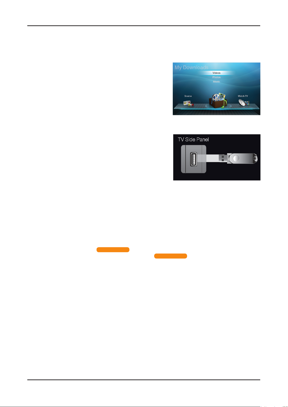
2-4-1. My Contents
Using the My Contents
Enjoy photos, music and/or movie files saved on a USB Mass Storage Class (MSC) device and/or your PC.
Press the 1. CONTENT button to select My Contents.
Press 2. u/d button to select desired menu (Videos,
Photos, Music), then press the ENTERE button.
* It may differ depending on the model.
Connecting a USB Device
Turn on your TV.1.
Connect a USB device containing photo, music and/or 2.
movie les to the USB jack on the side of the TV.
When USB is connected to the TV, popup window 3.
appears. Then you can select Connected Device.
* It may differ depending on the model.
N It might not work properly with unlicensed multimedia les.
N Need-to-Know List before using My Contents.
MTP (Media Transfer Protocol) is not supported.•
The le system supports FAT16, FAT32 and NTFS.•
Certain types of USB Digital camera and audio devices may not be compatible with this TV.•
• My Contents only supports USB Mass Storage Class (MSC) devices. MSC is a Mass Storage Class Bulk-Only Transport
device. Examples of MSC are Thumb drives, Flash Card Readers and USB HDD (USB HUB are not supported). Devices
should be connected directly to the TV’s USB port.
Before connecting your device to the TV, please back up your les to prevent them from damage or loss of data. SAMSUNG •
is not responsible for any data le damage or data loss.
USB (HDD) is not supported. •
Connect a USB HDD to the dedicated port, USB 1 (HDD) port. •
Do not disconnect the USB device while it is loading.•
The higher the resolution of the image, the longer it takes to display on the screen.•
The maximum supported JPEG resolution is 15360X8640 pixels.•
For unsupported or corrupted les, the “Not Supported File Format” message is displayed.•
If the les are sorted by Basic View, up to 1000 les can be displayed in each folder.•
MP3 les with DRM that have been downloaded from a non-free site cannot be played. Digital Rights Management (DRM) •
is a technology that supports the creation, distribution and management of the content in an integrated and comprehensive
way, including the protection of the rights and interests of the content providers, the prevention of the illegal copying of
contents, as well as managing billings and settlements.
If more than 2 PTP devices are connected, you can only use one at a time.•
If more than two MSC devices are connected, some of them may not be recognized. A USB device that requires high power •
(more than 500mA or 5V) may not be supported. If an over-power warning message is displayed while you are connecting
or using a USB device, the device may not be recognized or may malfunction.
If the TV has been no input during time set in Auto Protection Time, the Screensaver will run.•
The power-saving mode of some external hard disk drives may be released automatically when connected to the TV.•
If a USB extension cable is used, the USB device may not be recognized or the les on the device may not be read.•
If a USB device connected to the TV is not recognized, the list of les on the device is corrupted or a le in the list is not •
played, connect the USB device to the PC, format the device and check the connection.
If a le deleted from the PC is still found when • My Contents is run, use the “Empty the Recycle Bin” function on the PC to
permanently delete the le.
for LED 4000 series
for LED 5000 series
Page 18
2-12
2. Product specications
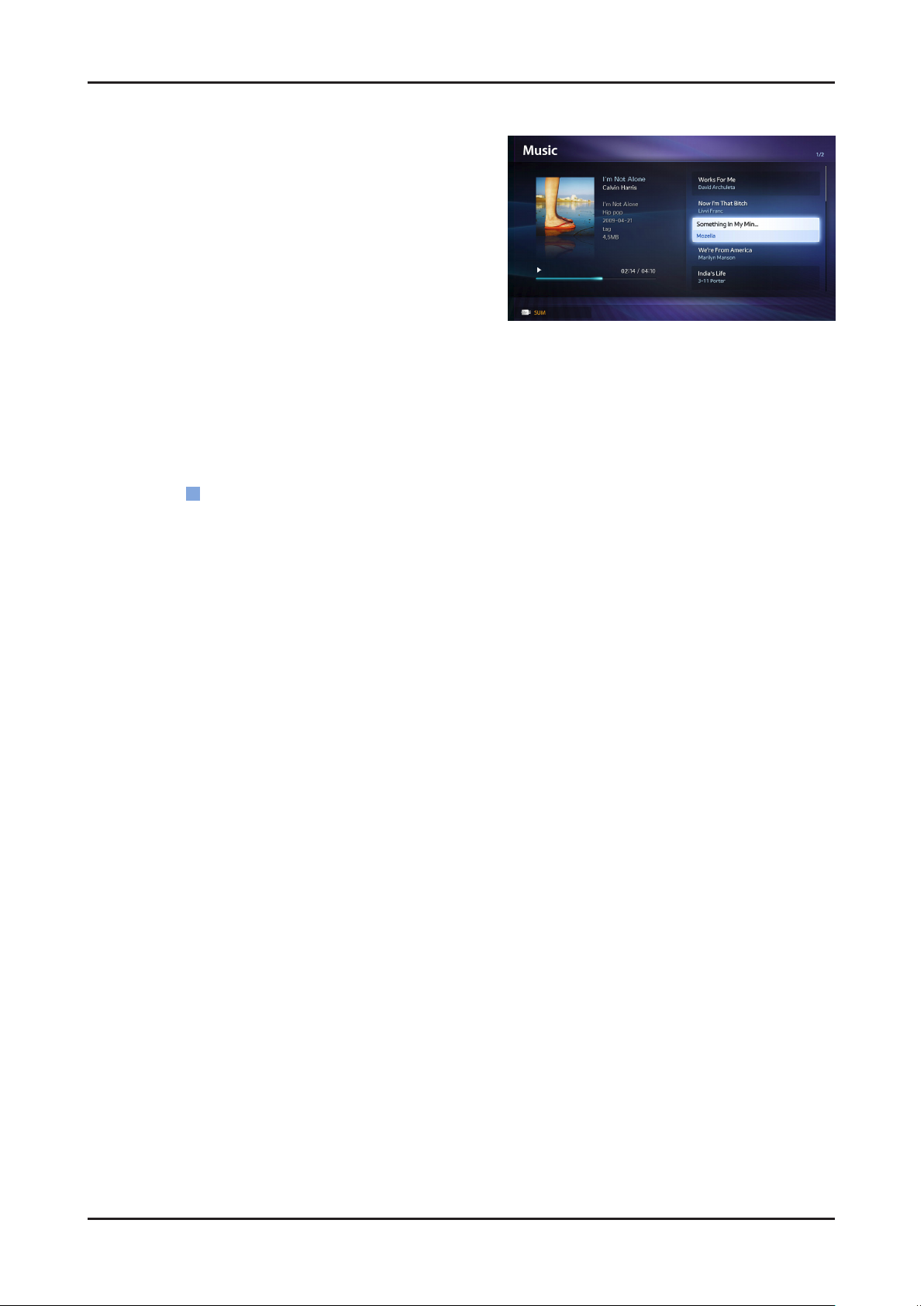
Music
Playing Music01.
Press the 1. ◄/►/▲/▼ button to select the desired Music in
the le list.
Press the 2. ENTERE button or (Play) button.
– You can use (REW) and μ (FF) buttons during
playback.
N Only displays the les with MP3 and PCM le extension. Other le extensions are not displayed, even if they are
saved on the same USB device.
N If the sound is abnormal when playing MP3 les, adjust the Equalizer in the Sound menu. (An over-modulated
MP3 le may cause a sound problem.)
Playing selected music02.
Press the 1.
Select the desired music.2.
– The check box appears to the left of the selected les.
Press the 3. TOOLS button and select Play Selected Contents.
– You can select or deselect all music pressing the Select All/Deselect All.
(Edit Mode) button.
C
Page 19

2-13
2. Product specications
Photos
Viewing a Photo (or Slide Show)01.
Press the 1. ◄/►/▲/▼ button to select the desired Music in
the le list.
Press the 2. ENTERE button or (Play) button.
– When a selected photo is displayed, press the
ENTERE button to start the slide show.
– During the slide show, all les in the le list will be
displayed in order.
N When you press the (Play) button in the le list, slide show will be started immediately.
N Music les can be automatically played during the Slide Show if the Background Music is set to On.
N The BGM Mode cannot be changed until the BGM has nished loading.
Page 20
2-14
2. Product specications
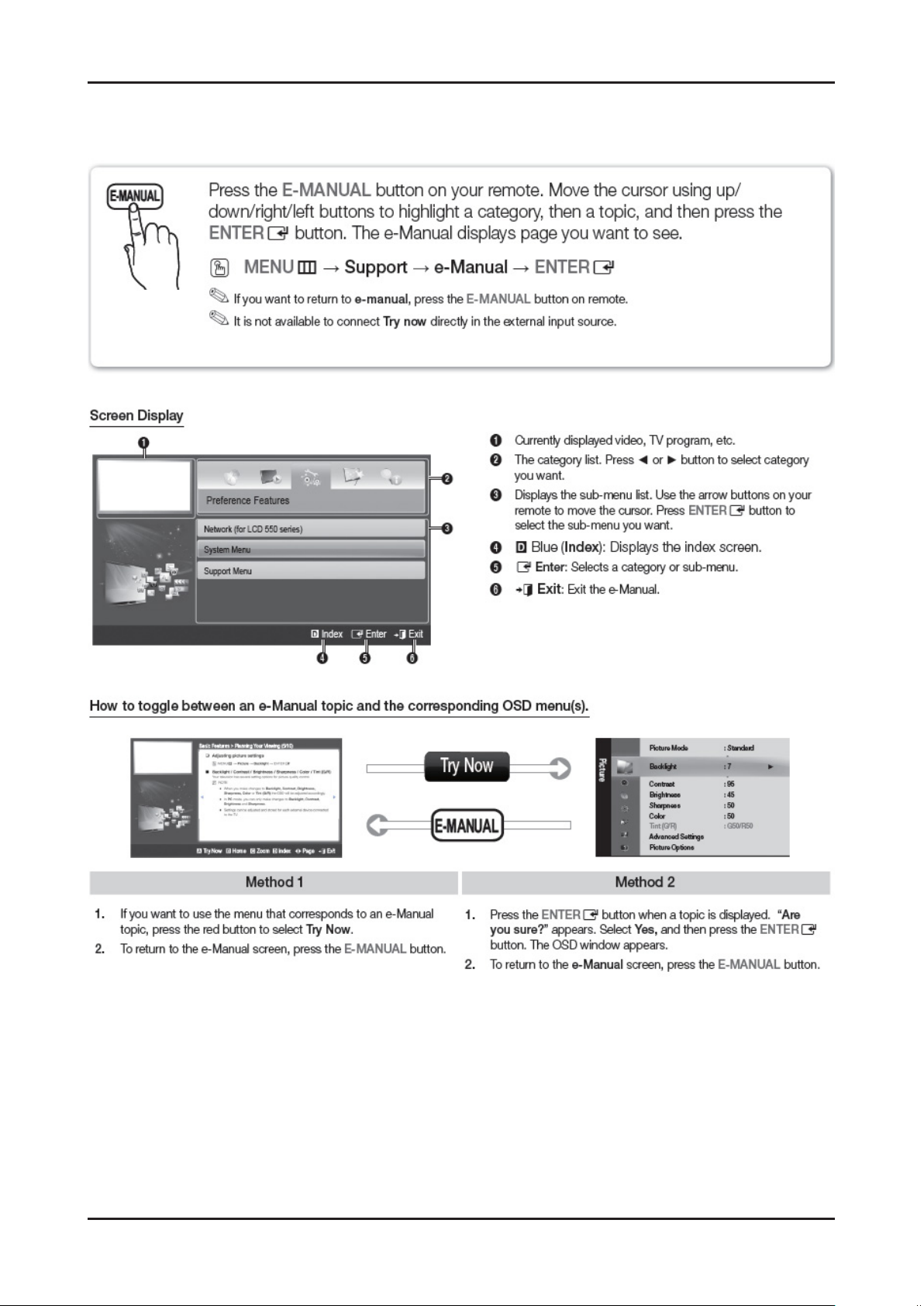
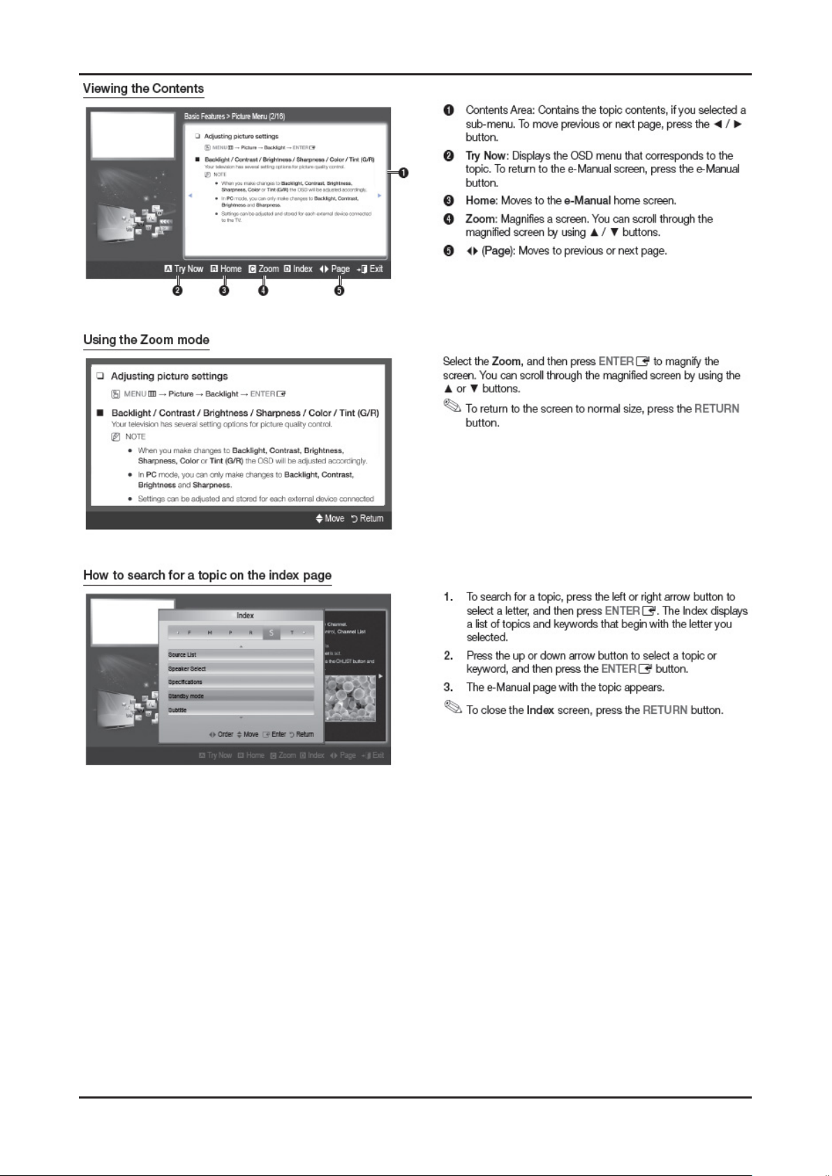
2-4-2. e-Manual
How to view the e-Manual
Page 21
2-15
2. Product specications
Page 22
3. Disassembly and Reassembly
3. Disassembly and Reassembly
This section of the service manual describes the disassembly and reassembly procedures for the LED/LCD TV.
WARNING:
This LED/LCD TV contains electrostatically sensitive devices. Use caution when handling these components.
3-1. Disassembly and Reassembly
Cautions: 1. Disconnect the
2. Follow these directions carefully; never use metal instruments to pry apart the cabinet.
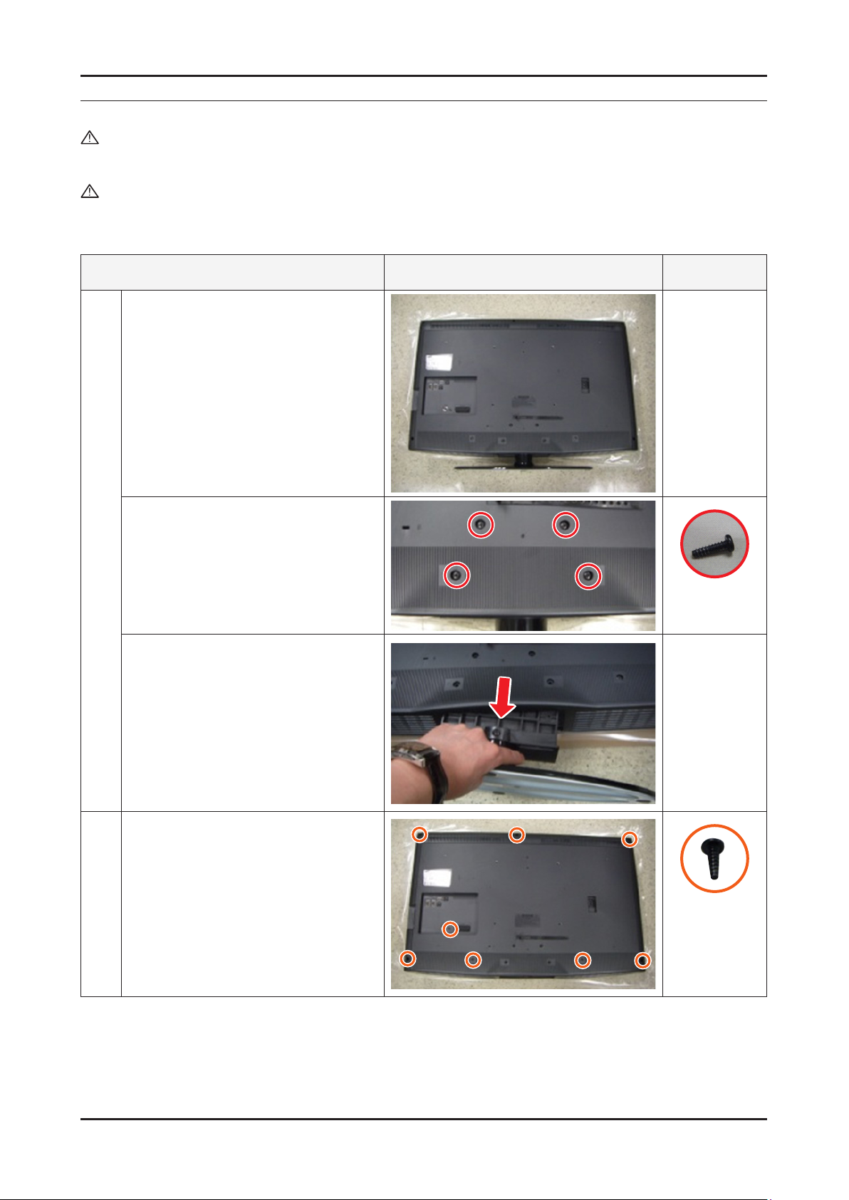
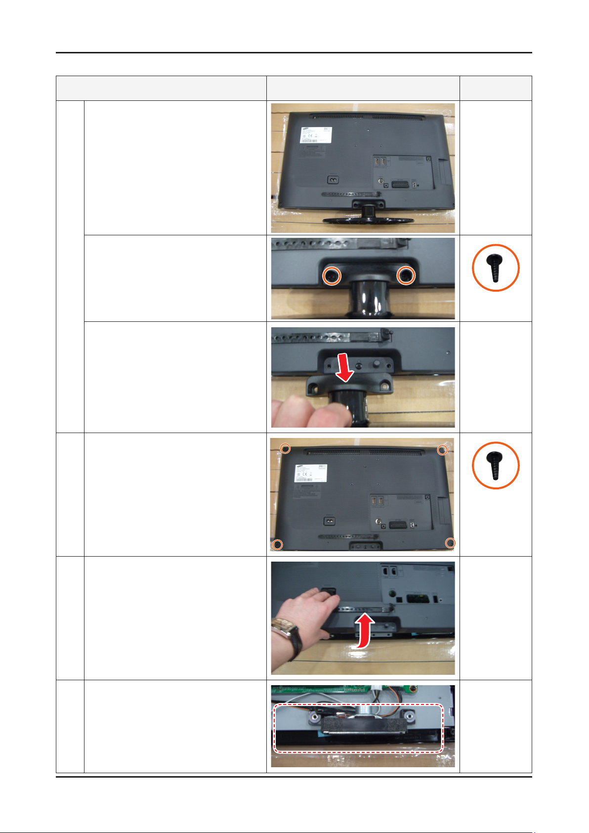
LE32D400
Description Picture Description Screws
Place the TV face down on cushioned table.
LED/LCD
TV from the power source before disassembly.
1
Remove 4 screws from the Stand.
Remove Stand.
Remove the screws of Rear-Cover.
2
32D400/32D403/32D503 : •
Remove the 8 screws.
6003-001785
6003-001782
3-1
Page 23
3-2
3. Disassembly and Reassembly
Description Picture Description Screws
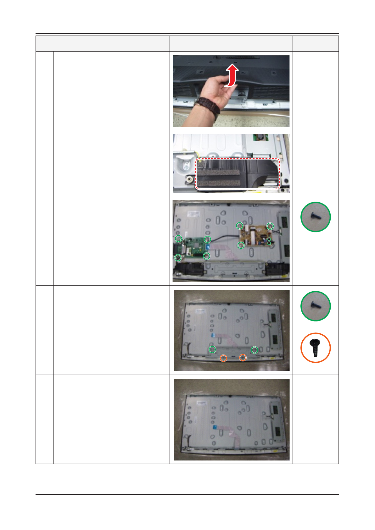
Lift up the Rear-Cover.
3
Remove the left and right speaker.
4
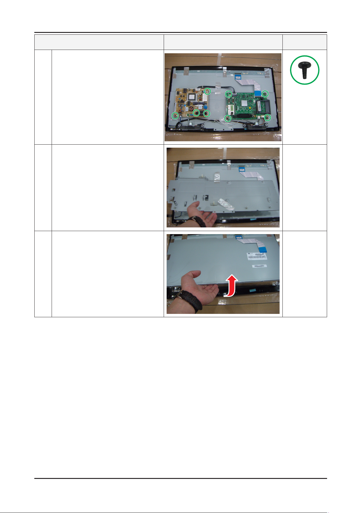
Remove the 4 screws of Main Board.
5
Remove the 5 screws of SMPS Board.
Remove the 6 screws of Bracket Stand Link &
6
Guide. (Machine type : 4 EA)
Remove the Stand Link.
7
6003-001782
6003-001782
6003-001782
Page 24
3-3
3. Disassembly and Reassembly
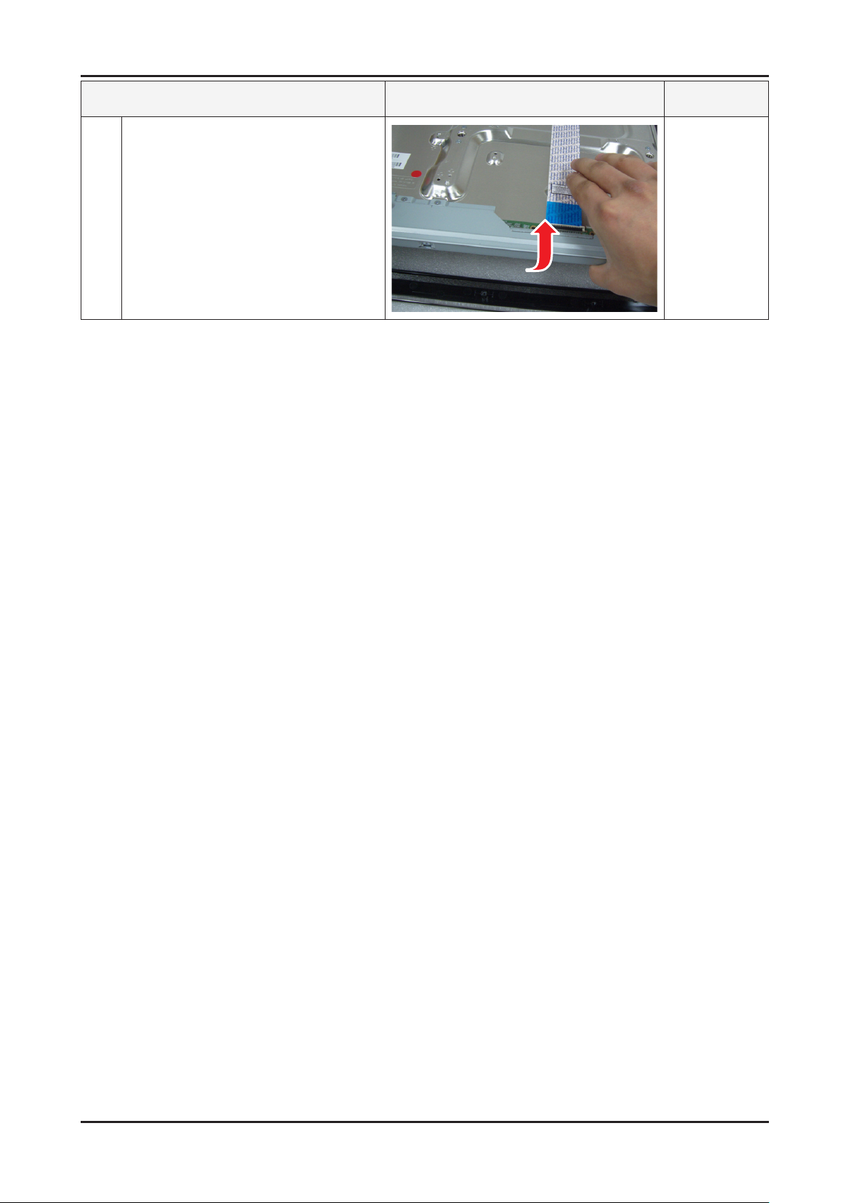
Lift up the Panel.
8
Reassembly procedures are in the reverse order of disassembly procedures. ※
Description Picture Description Screws
Page 25
3-4
3. Disassembly and Reassembly
UE32D4003
Description Picture Description Screws
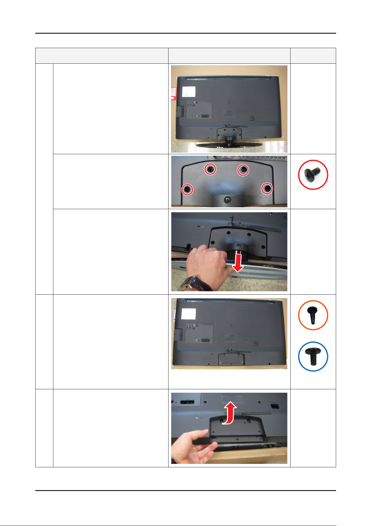
Place the TV face down on cushioned table.
1
Remove 4 screws from the Stand.(machine
type)
6001-002621
(Machine)
Remove Stand.
Remove the screws of Rear-Cover.
2
26D4003 :• Remove the 4 screws.
32D4003 :• Remove the 10 screws.
(machine type : 1 EA)
40D5003 :• Remove the 11 screws.
(machine type : 3 EA)
Lift up the Rear-Cover.
3
6003-001782
6001-002671
(Machine)
Page 26
3-5
3. Disassembly and Reassembly
Description Picture Description Screws
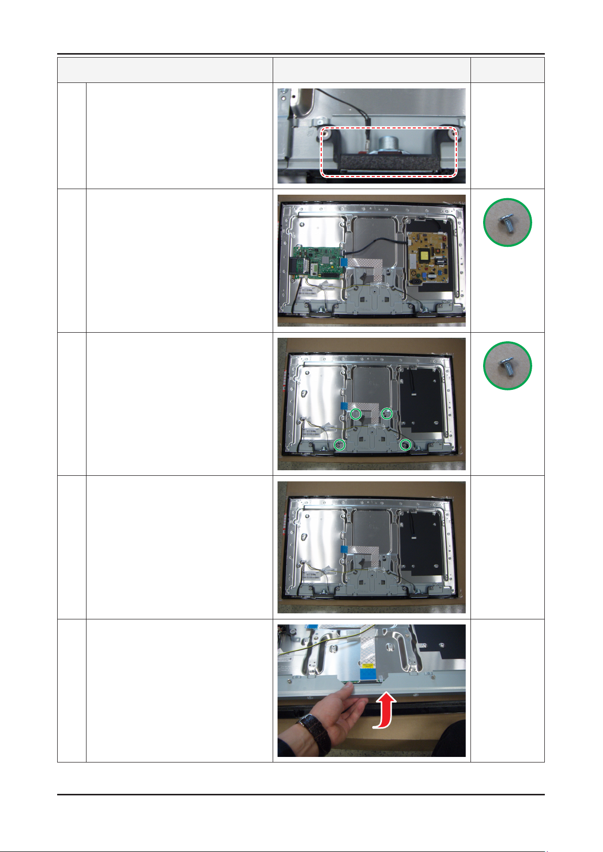
Remove the left and right speaker.
4
Remove the 4 screws of Main Board.
5
Remove the 5 screws of SMPS Board.
6001-002653
(Machine)
Remove the 4 screws of Bracket Stand Link
6
Remove the Stand Link.
7
Lift up the Panel.
8
6001-002653
(Machine)
Reassembly procedures are in the reverse order of disassembly procedures. ※
Page 27
3-6
3. Disassembly and Reassembly
UE22D5003
Description Picture Description Screws
Place the TV face down on cushioned table.
1
Remove 2 screws from the stand.
(machine type)
6003-001782
Remove Stand.
Remove the screws of Rear-Cover.
2
19D4003/22D5003 : Remove the 4 screws.•
Lift up the Rear-Cover.
3
6003-001782
Remove the left and right speaker.
4
Page 28
3-7
3. Disassembly and Reassembly
Description Picture Description Screws
Remove the 4 screws of Main Board.
5
Remove the 3 screws of SMPS Board.
Remove the Stand Link.
6
6003-000115
Lift up the Panel.
7
Reassembly procedures are in the reverse order of disassembly procedures. ※
Page 29

4. Troubleshooting
4-1. Troubleshooting
4-1-1. Previous check
Check the various cable connections rst. 1.
• Check to see if any cables are damaged or burnt.
• Check to see if there is a disconnected or loose cable connection.
• Check to see if the cables are connected according to the connection diagram.
Check the power input to the Main Board.2.
UD4003(19", 26", 32")
UD5003(22", 40")
MAIN BOARD
4. Troubleshooting
SMPS BOARD
UD4003(19")
UD5003(22")
LD400 / LD403(32")
LD503(40")
T-CON
SMPS BOARD
MAIN BOARD
SMPS BOARD
MAIN BOARD
T-CON
4-1
Page 30

4-2
4. Troubleshooting
4-1-2. Flip (UE40D5003BW*** / UE26/32D4003BW*** / LE40D503F7W*** / LE32D400E1W*** / LE32D403E2W***)
No Power
The LEDs on the front panel do not work when connecting the power cord. -
Symptom
Major
checkpoints
The SMPS relay does not work when connecting the power cord. The units appears to be dead. -
The IP relay or the LEDs on the front panel does not work when connecting the power cord if the cables are
improperly connected or the Main Board or SMPS is not functioning. In this case, check the following:
Check the internal cable connection status inside the unit. Check the fuses of each part. Check the output voltage of SMPS. Replace the Main Board. -
Diagnostics
Lamp(Backlight) Off,
power indicator LED on?
Yes
Lamp(Backlight) Off,
power indicator LED on ?
Yes
Does proper Stand-By DC A5V
appear at VIA - A5V_PW ?
Yes
Does proper Main DC B13V, B5V
appear at VIA - B13V_PW, B5V_PW ?
Yes
Does proper DC A3.3V
appear at VIA - A3.3V_PW ?
Yes
No
No
No
No
No
Change the 14p power cable.
Change INVERTER/BALANCE B'D.
Change the Main Assy.
Does proper B3.3V, B1.5V appear at
VIA - B3.3V_PW, B1.5V_PW
Yes
Does proper DC B13V
appear at LVDS connector
Pin #1~5 of T-con b'd?
Yes
Does proper DC B13V
appear at F1 of T-con b'd?
Yes
A power is supplied to set?
Caution Make sure to disconnect the power before working on the IP board.
No
No
No
No
Change the LVDS cable.
Change the T-con b'd.
Check a other function.
(No picture part)
Replace a LCD Panel.
Page 31

4-3
4. Troubleshooting
Main Board_Bottom
Page 32

4-4
4. Troubleshooting
No video (HDMI 1, 2 - Digital signal)
Symptom
Major
checkpoints
Audio is normal but no picture is displayed on the screen. -
Check the HDMI source. Check the HDMI switch, Check the Main Chipset. -
This may happen when the LVDS cable connecting the Main Board and the Panel is disconnected. -
Power indicator LED is off.
Lamp(Backlight) on, no video ?
Yes
Check the HDMI source and
check the connection of HDMI cable ?
Yes
Does the signal appear at
3
CN601 (Pin#12 , #7 )(HDMI1)
CN604 (Pin#12 , #7 )(HDMI2)
(HDMI RX_Clk , RX_Data) ?
Yes
No
No
No
Check a set in the 'Stand-by mode'.
Input the HDMI signal properly.
Check CN601, CN604
CN602, CN603.
Check HDMI cable.
Change the Main Assy.
Diagnostics
2
Does the digital data appear at
TP-E_TXCLK+, E_TXCLK- ,
O_TXCLK+, O_TXCLK- ?
Yes
Check the LVDS cable?
Check the T-Con B'd?
Replace the LCD panel?
No
No
Check IC1001 (X6).
Change the Main Assy.
Please, Contact Tech support.
Caution Make sure to disconnect the power before working on the IP board.
Page 33

4-5
4. Troubleshooting
Main Board_Top
Page 34

4-6
4. Troubleshooting
WAVEFORMS
3
2
HDMI input (RX_Data, RX_Clk)
LVDS output
Page 35

4-7
4. Troubleshooting
No Video (Tuner_CVBS)
Symptom
Major
checkpoints
2
Audio is normal but no picture is displayed on the screen. -
Check the Tuner CVBS source. Check the Tuner, Check the Main Chipset. -
This may happen when the LVDS cable connecting the Main Board and the Panel is disconnected. -
Power indicator LED is off.
Lamp(Backlight) on, no video ?
Yes
Check the RF source and
check the connection of RF cable ?
Yes
Does the DC TU5V_PW, TU33V_PW
appear at TP - TUNER_33V, B 5V
Pin of Tuner ?
Yes
Does the digital data appear at
TP-E_TXCLK+, E_TXCLK- ,
O_TXCLK+, O_TXCLK- ?
No
No
No
No
Check a set in the 'Stand-by mode'
Input the RF source properly.
Change the Main Assy.
Check IC1001 (X6).
Change the Main Assy.
Diagnostics
Yes
Check the LVDS cable?
Check the T-Con B'd?
Replace the LCD panel?
No
Please, Contact Tech support.
Caution Make sure to disconnect the power before working on the IP board.
Page 36

4-8
4. Troubleshooting
Main Board_Top
Page 37

4-9
4. Troubleshooting
WAVEFORMS
LVDS output
2
Page 38

4-10
4. Troubleshooting
No Video (Tuner DTV)
Symptom
Major
checkpoints
Audio is normal but no picture is displayed on the screen. -
Check the DTV source. Check the Tuner, Check the Main Chipset. -
This may happen when the LVDS cable connecting the Main Board and the Panel is disconnected. -
Power indicator LED is off.
Lamp(Backlight) on, no video ?
Yes
Check the RF source and
check the connection of RF cable ?
Yes
Check the 'signal strength' in Self Diagnosis
menu Strength is enough ?
Yes
Does the DC B5V_TU_PW, B33V_TU_PW
appear at #3, #5 Pin of Tuner ?
No
No
No
No
Check a set in the 'Stand-by mode'
Input the RF source properly.
Check the D-TV source.
Change the Main Assy.
Diagnostics
2
Yes
Does the digital data appear at
TP-E_TXCLK+, E_TXCLK- ,
O_TXCLK+, O_TXCLK- ?
Yes
Check the LVDS cable?
Check the T-Con B'd?
Replace the LCD panel?
No
No
Check IC1001 (X6).
Change the Main Assy.
Please, Contact Tech support.
Caution Make sure to disconnect the power before working on the IP board.
Page 39

4-11
4. Troubleshooting
Main Board_Top
Page 40

4-12
4. Troubleshooting
WAVEFORMS
2
LVDS output
Page 41

4-13
4. Troubleshooting
No Video (Video CVBS)
Symptom
Major
checkpoints
4
2
Audio is normal but no picture is displayed on the screen. -
Check the Video CVBS source -
Check the Main Chipset. -
This may happen when the LVDS cable connecting the Main Board and the Panel is disconnected. -
Power indicator LED is off.
Lamp(Backlight) on, no video ?
Yes
Check the video source and
check the connection of video cable?
Yes
Does the CVBS data appear at
PIN - COMP1_Y_CVBS ?
Yes
Does the digital data appear at
TP-E_TXCLK+, E_TXCLK- ,
O_TXCLK+, O_TXCLK- ?
No
No
No
No
Check a set in the 'Stand-by mode'.
Input the video source properly.
Check CN503.
Change the Main Assy.
Check IC1001 (X6).
Change the Main Assy.
Diagnostics
Yes
Check the LVDS cable?
Check the T-Con B'd?
Replace the LCD panel?
No
Please, Contact Tech support.
Caution Make sure to disconnect the power before working on the IP board.
Page 42

4-14
4. Troubleshooting
Main Board_Top
Page 43

4-15
4. Troubleshooting
WAVEFORMS
CVBS OUT (Grey Bar)
4
LVDS output
2
Page 44

4-16
4. Troubleshooting
No Sound
Symptom
Major
checkpoints
Video is normal but there is no sound.. -
When the speaker connectors are disconnected or damaged. When the sound processing part of the Main Board is not functioning. Speaker defect. -
Check the source and
check the connection of sound cable
(Comp/PC/DVI to HDMI) ?
Yes
Does the sound data appear at
PIN - COMP1_SR_IN,
COMP1_SL_IN
VIA - PC_DVI_SR_IN,
PC_DVI_SL_IN (PC/DVI) ?
Yes
Does the DC B12VS appear at
CN201 PIN 7,9 - B12VS_PW ?
Yes
No
No
No
Input the sound source properly.
Check CN503, CN402.
Change the Main Assy.
Change the Main Assy.
Diagnostics
7
Does the sound data appear at
TP - SPK_ L-, SPK_L+, SPK_R-, SPK_R+ ?
Yes
Replace speaker ?
TBD
No
No
Check IC1001 (X6).
Change the Main Assy.
Please, Contact Tech support.
Caution Make sure to disconnect the power before working on the IP board.
Page 45

4-17
4. Troubleshooting
Main Board_Bottom
Page 46

4-18
4. Troubleshooting
WAVEFORMS
Speaker out
7
Page 47

4-19
4. Troubleshooting
4-1-3. Non Filp (UE22D5003BW*** / UE19D4003BW***)
No Power
The LEDs on the front panel do not work when connecting the power cord. -
Symptom
Major
checkpoints
The SMPS relay does not work when connecting the power cord. The units appears to be dead. -
The IP relay or the LEDs on the front panel does not work when connecting the power cord if the cables are
improperly connected or the Main Board or SMPS is not functioning. In this case, check the following:
Check the internal cable connection status inside the unit. Check the fuses of each part. Check the output voltage of SMPS. Replace the Main Board. -
Diagnostics
Lamp(Backlight) Off,
power indicator LED on?
Yes
Lamp(Backlight) Off,
power indicator LED on ?
Yes
Does proper Stand-By DC A5V
appear at VIA - A5V_PW ?
Yes
Does proper Main DC B13V, B5V
appear at VIA - B13V_PW, B5V_PW ?
Yes
Does proper DC A3.3V
appear at VIA - A3.3V_PW ?
Yes
No
No
No
No
No
Change the 14p power cable.
Change INVERTER/BALANCE B'D.
Change the Main Assy.
Does proper B3.3V, B1.5V appear at
VIA - B3.3V_PW, B1.5V_PW
Yes
Does proper DC B13V appear at
LVDS connector Pin #1~5 of Panel ?
Yes
A power is supplied to set?
Caution Make sure to disconnect the power before working on the IP board.
No
No
No
Change the LVDS cable.
Check a other function.
(No picture part)
Replace a LCD Panel.
Page 48

4-20
4. Troubleshooting
Main Board_Bottom
Page 49

4-21
4. Troubleshooting
No video (HDMI 1, 2 - Digital signal)
Symptom
Major
checkpoints
Audio is normal but no picture is displayed on the screen. -
Check the HDMI source. Check the HDMI switch, Check the Main Chipset. -
This may happen when the LVDS cable connecting the Main Board and the Panel is disconnected. -
Power indicator LED is off.
Lamp(Backlight) on, no video ?
Yes
Check the HDMI source and
check the connection of HDMI cable ?
Yes
Does the signal appear at
3
CN601 (Pin#12 , #7 )(HDMI1)
CN604 (Pin#12 , #7 )(HDMI2)
(HDMI RX_Clk , RX_Data) ?
Yes
No
No
No
Check a set in the 'Stand-by mode'.
Input the HDMI signal properly.
Check CN601,CN602.
Check HDMI cable.
Change the Main Assy.
Diagnostics
2
Does the digital data appear at
TP-E_TXCLK+, E_TXCLK- ,
O_TXCLK+, O_TXCLK-
Yes
Check the LVDS cable?
Check the T-Con B'd?
Replace the LCD panel?
No
No
Check IC1111 (X5).
Change the Main Assy.
Please, Contact Tech support.
Caution Make sure to disconnect the power before working on the IP board.
Page 50

4-22
4. Troubleshooting
Main Board_Top
Page 51

4-23
4. Troubleshooting
WAVEFORMS
3
2
HDMI input (RX_Data, RX_Clk)
LVDS output
Page 52

4-24
4. Troubleshooting
No Video (Tuner_CVBS)
Symptom
Major
checkpoints
Audio is normal but no picture is displayed on the screen. -
Check the Tuner CVBS source. Check the Tuner, Check the Main Chipset. -
This may happen when the LVDS cable connecting the Main Board and the Panel is disconnected. -
Power indicator LED is off.
Lamp(Backlight) on, no video ?
Yes
Check the RF source and
check the connection of RF cable ?
Yes
Does the DC B5V_TU_PW, B33V_TU_PW
appear at #2, #4 Pin of Tuner ?
Yes
Does the digital data appear at
2
TP-E_TXCLK+, E_TXCLK- ,
O_TXCLK+, O_TXCLK- ?
No
No
No
No
Check a set in the 'Stand-by mode'
Input the RF source properly.
Change the Main Assy.
Check IC1111 (X5).
Change the Main Assy.
Diagnostics
Yes
Check the LVDS cable?
Check the T-Con B'd?
Replace the LCD panel?
No
Please, Contact Tech support.
Caution Make sure to disconnect the power before working on the IP board.
Page 53

4-25
4. Troubleshooting
Main Board_Top
Page 54

4-26
4. Troubleshooting
WAVEFORMS
LVDS output
2
Page 55

4-27
4. Troubleshooting
No Video (Tuner DTV)
Symptom
Major
checkpoints
Audio is normal but no picture is displayed on the screen. -
Check the DTV source. Check the Tuner, Check the Main Chipset. -
This may happen when the LVDS cable connecting the Main Board and the Panel is disconnected. -
Power indicator LED is off.
Lamp(Backlight) on, no video ?
Yes
Check the connection of RF cable ?
Yes
Check the 'signal strength' in Self Diagnosis
menu Strength is enough?
Yes
Does the DC B5V_TU_PW, B33V_TU_PW
appear at #2, #4 Pin of Tuner ?
No
No
No
No
Check a set in the 'Stand-by mode'
Input the RF source properly.
Check the D-TV source.
Change the Main Assy.
Diagnostics
2
Yes
Does the digital data appear at
TP-E_TXCLK+, E_TXCLK- ,
O_TXCLK+, O_TXCLK-?
Yes
Check the LVDS cable?
Check the T-Con B'd?
Replace the LCD panel?
No
No
Check IC1111 (X5).
Change the Main Assy.
Please, Contact Tech support.
Caution Make sure to disconnect the power before working on the IP board.
Page 56

4-28
4. Troubleshooting
Main Board_Top
Page 57

4-29
4. Troubleshooting
WAVEFORMS
2
LVDS output
Page 58

4-30
4. Troubleshooting
No Video (Video CVBS)
Symptom
Major
checkpoints
4
2
Audio is normal but no picture is displayed on the screen. -
Check the Video CVBS source -
Check the Main Chipset. -
This may happen when the LVDS cable connecting the Main Board and the Panel is disconnected. -
Power indicator LED is off.
Lamp(Backlight) on, no video ?
Yes
Check the video source and
check the connection of video cable?
Yes
Does the CVBS data appear at
PIN - COMP2_Y_CVBS ?
Yes
Does the digital data appear at
TP-E_TXCLK+, E_TXCLK- ,
O_TXCLK+, O_TXCLK- ?
No
No
No
No
Check a set in the 'Stand-by mode'.
Input the video source properly.
Check CN502_NEU.
Change the Main Assy.
Check IC1111 (X5).
Change the Main Assy.
Diagnostics
Yes
Check the LVDS cable?
Check the T-Con B'd?
Replace the LCD panel?
No
Please, Contact Tech support.
Caution Make sure to disconnect the power before working on the IP board.
Page 59

4-31
4. Troubleshooting
Main Board_Top
Page 60

4-32
4. Troubleshooting
WAVEFORMS
CVBS OUT (Grey Bar)
4
LVDS output
2
Page 61

4-33
4. Troubleshooting
No Sound
Symptom
Major
checkpoints
Video is normal but there is no sound.. -
When the speaker connectors are disconnected or damaged. When the sound processing part of the Main Board is not functioning. Speaker defect. -
Check the source and
check the connection of sound cable ?
(HDMI)
Yes
Does the sound data appear at
PIN - COMP2_SR_IN,COMP2_SL_IN ?
Yes
Does the DC B12VS appear at
CN201 PIN 7,9 - B12VS_PW ?
Yes
No
No
No
Input the sound source properly.
Check CN502_NEU.
Change the Main Assy.
Change the Main Assy.
Diagnostics
7
Does the sound data appear at
TP - SPK_ L-, SPK_L+, SPK_R-, SPK_R+ ?
Yes
Replace speaker ?
No
No
Check IC1111 (X5).
Change the Main Assy.
Please, Contact Tech support.
Caution Make sure to disconnect the power before working on the IP board.
Page 62

4-34
4. Troubleshooting
Main Board_Bottom
Page 63

4-35
4. Troubleshooting
WAVEFORMS
Speaker out
7
Page 64

4-36
4. Troubleshooting
4-2. Alignments and Adjustments
4-2-1. General Alignment Instuction
Usually, a color LED/LCD TV needs only slight touch-up adjustment upon installation. 1.
Check the basic characteristics such as height, horizontal and vertical sync.
Use the specied test equipment or its equivalent.2.
Correct impedance matching is essential.3.
Avoid overload. Excessive signal from a sweep generator might overload the front-end of the TV. 4.
When inserting signal markers, do not allow the marker generator to distort test result.
Connect the TV only to an AC power source with voltage and frequency as specied on the backcover nameplate.5.
Do not attempt to connect or disconnect any wire while the TV is turned on. 6.
Make sure that the power cord is disconnected before replacing any parts.
To protect against shock hazard, use an isolation transformer.7.
Page 65

4-37
4. Troubleshooting
4-3. Factory Mode Adjustments
4-3-1. Entering Factory Mode
To enter ‘Service Mode’ Press the remote -control keys in this sequence :
- If you do not have Factory remote - control
- If you have Factory remot - control
INFO FACTORY KEY
INFOPower OFF Power ONMENU MUTE
4-3-2. How to Access Service Mode
Using the Customer Remote
Turn the power off and set to stand-by mode.1.
Press the remote buttons in this order; POWER OFF- INFO - MENU - MUTE to turn the set on.2.
The set turns on and enters service mode. This may take approximately 20 seconds.3.
Press the Power button to exit and store data in memory. 4.
- If you fail to enter service mode, repeat steps 1 and 2 above.
Initial SERVICE MODE DISPLAY State5.
Option
Control
SVC
Expert
ADC/WB
Advanced
T-MSU ♠ D ♣ ♣ C-XXXX
T-MSU ♠ D ♣ ♣ S-XXXX
E-Manual : XXXXXXXXXX-XXXX
EDID SUCCESS
HDCP SUCCESS
CALIB : AV / COMP / PC / HDMI /
Option : XXXX XXXX
T-MSXDXX-XXXX
SDAL-X.XX.X.X
RFS : "Mstar-X5 XXXX"
20XX-XX-XX
F-ET-0xXX-XXXX
Type : XXXXXXXX
Model : XXXXXXXX
CIP SUCCESS LOCK X
Factory Data Ver : XX
EERC Version : XXX
DTP-AP-COMP-XXX
DTP-BP-HAL-XXXX
DTP-BP-XXXX-XX
Date Of Purchase : XX/XX/XXXX
♠ OPTION (Option-Model)
5 X5-TV
♣ ♣ OPTION (Option-Local Set)
EU EU / EU_* / NORDIG / CIS_* / AD_*
LD400 / LD403 / LD503 /
UD4003 / UD5003
* How to enter the hidden factory mode.
a. into the factory mode
b. move the tap to Advanced
c. key input : 0 + 0 + 0 + 0
** hidden menu : Advanced
6. Buttons operations withn Service Mode
Menu Full Menu Display/Move to Parent Menu
Direction Keys /
Direction Keys /
Source
Item Selection by Moving the Cursor
Data Increase / Decrease for the Selected Item
Cycles through the active input source that are connected to the unit
Page 66

4-38
4. Troubleshooting
4-3-3. Factory Data
Option
Factory Name Data Range Use
Factory Reset
19A6TH0C/19I6TH0C/22D6TF0C/22I6TF0C
/26A6AH0C/26D6AH0C/26L6AH0C/32A6AF0C
/32A6AH0C/32D6AF0C/32L6AH0C/37L6AF0C
/40A6AF0C/40D6AF0C/40L6AF0C/46A6AF0C
/46D6AF0C/19A6TH0E/19L6TH0E/22D6TF0E
Type
Local Set EU
/22L6TF0E/23A6TF0E/24L6TF0E/27A6TF0E
/32A6AH0E/32A6UF0E/32P6AH0E/32P6UF0E
/32L6UF0E/32L6AH0E/37P6UF0E/40A6UF0E
/40P6UF0E/40H6UF0E/46A6UF0E/46P6UF0E
/43DHHcD/51DFHcD/51DHHcD/51DSArD/51DSCrD
/59DFHcD/59DSArD/59DSCrD/64DFHcD/64DSCrD
EU/EU_ITALY/EU_GER/EU_FRANCE
/EU_BENELUX/EU_UK/EU_ARMENIA/NORDIG
/AD_AU/AD_NZ/AD_SINGAPOL/CIS_RUSIA
/CIS_UKRINA/CIS_KAZAKH/EU_TURKEY
/EU_AFRICA/EU_MOROCO/EA_VIET/EA_THAI
/EA_INA/EA_CHINA/EA_INDIA/EA_SRILANKA
/EA_NEPAL/EA_BANGLA/EA_IRAN/EA_ISRAEL
/EA_EGYPT/EA_LIBYA/EA_CIS/EA_M_ASIA
/EA_IRAQ/EA_ARAB/EA_SAUDI/EA_PAKISTAN
/EA_E_ASIA/EA_AFRICA/EA_S_AFRICA/EA_MAL
/EA_PHI/ED_IRAN/ED_VIET/ED_INA/ED_ISRAEL
/COLOMBIA/TAIWAN
Select Panel Type
: inch
: vendor
: refresh
: POL
: resolution
: multi
: BLU
Select Area
Model LD550
TUNER SEC_TC
Ch Table
Front Color
LD400 / LD450 / LD480 / LD550 / LD570 / LD580
/ UD4000 / UD4010 / UD5000 / UD5500 / UD5550
/ UD5700 / PD450 / PD451 / PD460 / PD490 /
PD491 / PD540 / PD541 / PD550 / PD551 / PD560
/ PD570 / PD6400 / PD6500 / PD6600 / PD6900 /
PD7000 / LD460H / LD463H / LD467H / LD468H /
LD560H / LD568H / LD580H / UD4000H / UD5000H
/ UD5500H / LD567H / PD6452 / PD6910 / PD580 /
PD480 / PD452 / PD420 / LD430 / LD530 / UD4020
/ UD5010 / LD531 / LD551 / PD495 / PD6905 /
PD6915 / PD7005 / UD5030 / LD451 / LD455 /
LD481 / LD555 / LD556 / LD575 / LD578 / LD579
/ LD585 / UD4005 / UD4015 / UD4025 / UD5005 /
UD5015 / UD5020 / UD5025 / UD5520 / UD5705
/ UD5720 / UD5725 / LD452 / LD552 / LD400E /
LD403 / LD503 / UD4003 / UD5003 / UD5800 /
PD530 / PD6980 / LD461H / LD561H /
SEC_ATSC / SEC_TC / ALPS_TC / SI_TCS / SI_T2
/ SEC_ISDB / SEC_ATC / SI_ATC / SI_TW
PBA / SUWON / SESK / SEH / SERK / SDMA_AU /
SDMA_NZ / SDMA_SG / SEIN / SAVINA / SIEL_C /
SIEL_N / TTSEC / TSED / TSE / IRAN / SESK-T2 /
SUWON-T2 / INL
P-S-C-BK / P-S-R-BK / P-S-BK / P-S-B-BK / P-T-R-
BK / P-T-C-BK / P-T-W-Bn / P-T-W-Gy / P-T-M-Bn
/ P-T-C-Gy / P-T-R-Gy / P-W-Milk / P-W-M-Wt /
P-W-D-Gy / P-W-Vio / L-S-C-BK / L-S-R-BK / L-S-
BK / L-S-B-BK / L-T-R-BK / L-T-C-BK / L-T-W-Bn /
L-T-W-Gy / L-T-M-Bn / L-T-C-Gy / L-T-R-Gy / L-WMilk / L-W-M-Wt / L-W-D-Gy / L-W-Vio / U-S-C-BK /
U-S-R-BK / U-S-BK / U-S-B-BK / U-T-R-BK / U-T-C-
BK / U-T-W-Bn / U-T-W-Gy / U-T-M-Bn / U-T-C-Gy
/ U-T-R-Gy / U-T-BL-M / U-T-BK-M / U-TC-L-M /
U-W-Milk / U-W-M-Wt / U-W-D-Gy / U-W-Vio
Select Model
EU/AU(DVB-TC/DVB-T) :
SEC_TC
LD503 : L-S-BK
UD5003 : U-S-BK
Page 67

4-39
4. Troubleshooting
Control
Factory Name Data Range Use
EDID
EDID ON/OFF OFF
EDID WRITE ALL …
EDID WRITE PC …
EDID WRITE HDMI …
EDID WRITE HDMI1 …
EDID WRITE HDMI2 …
EDID WRITE HDMI3 …
EDID WRITE HDMI4 …
EDID VER …
EDID PORT …
EDID WRITE DVI …
Sub Option
RS-232 Jack UART Debug/Logic/UART
Watchdog ON ON/OFF
WD Count 0 255
Download EDID data to EEPROM.
1. Set "ON" of EDID ON/OFF
2. Go EDID WRITE ALL and Push
Enter or button.
3. If You See Success message, SET
"OFF" of EDID ON/OFF
Case of HDMI 1.2 EDID Service
1. Go EDID VER and Set HDMI 1.2
2. Go EDID PORT and Select HDMI
port
Select Setting of UART port.
Initial value is "UART"
Select Watchdog.
Initial value is "ON"
Watchdog Count.
Read Only.
Dimm Type EXT xed
Lvds Format JEIDA JEIDA/VESA/19INCH
OTN Server Type operating operating/development
OTN Test Server OFF OFF/ A/B/C/D/E Zone
OTN Support ON ON/OFF
OTN Reset not modifyed
OTN Duration OFF ON/OFF
OTN Fail Test OFF ON/OFF
View Log not modifyed
Select Dimming Type.
Initial value is "EXT"
Select LVDS format.
19/22/27inch :"VESA"
other inch :"JEIDA"
Page 68

4-40
4. Troubleshooting
LD400 : 72
LD45*/LD48*/LD5** : 36
KEY SENSITIVITY 36 0~255
Hotel Option
UD40** : 38 UD50** : 41
UD55**/UD57** :36
TA350 : 32 TA550 : 34
Hotel Hospitality OFF
Shop Option
Shop Mode OFF ON/OFF
Exhibition Mode OFF ON/OFF
Sound
High Devi OFF ON/OFF
Carrier_Mute OFF ON/OFF
Speaker Delay Normal 10 0~255 Audio delay for Lipsync
Pilot Level High Thld 0x28h 0x00~0xff
Pilot Level Low Thld 0x10h 0x00~0xff
Control for ATV sound of stereo
/multiplex
Control for ATV sound of stereo
/multiplex
Speaker EQ ON ON/OFF Control for sound precision
SVC
Factory Name Data Range Use
Test Pattern
Panel Auto Setting
Panel Display Time 0Hr
Logic Usb D/L off
Tuner Status
T-CON Usb Download
Set ONSub micom upgrade
MICOM UPGRADE off
BT ADDRESS 0
BT UPGRADE
SVC Reset
Test Pattern
Pattern Sel OFF
OFF/White/Black/Red/Green/Blue/
Cross/OneDot/ColorBar/GrayStep
,after upgrade Main Micom
(over 5 minutes)
"Test for Input of Scaler.
If you can see pattern well, there
is problem at input of Scaler."
Logic Pattern Sel … Not modied
Logic Level Sel … Not modied
TUNER STATUS
DVB
ISDB-T
DVB
SNR Not modied
BER Not modied
Singal Strength Not modied
Page 69

4-41
4. Troubleshooting
Bandwidth Not modied
Frequency Not modied
LNA Status Not modied
FFT Not modied
Modulation Not modied
Code Rate Not modied
GI Not modied
Hier Modulation Not modied
Frequency Offset Not modied
Timing Offset Not modied
AGC Not modied
UCB Not modied
PLL Type Not modied
DEMOD Type Not modied
TPS LOCK Not modied
RS Lock Not modied
SSI Not modied
SQI Not modied
ISDB-T
FFT Size_1 Not modied
Guard Interval_1 Not modied
Freq. Offset_1 Not modied
SNR_1 Not modied
IF AGC_1 Not modied
TMCC Lock_1 Not modied
TS Packet_1 Not modied
Master Lock_1 Not modied
A_Modulation_1 Not modied
A_Code Rate_1 Not modied
A_Timer InterLeave_1 Not modied
A_Segments Num_1 Not modied
A_Ber_1 Not modied
B_Modulation_! Not modied
B_Code Rate_1 Not modied
B_Timer InterLeave_1 Not modied
B_Segments Num_1 Not modied
B_BER_1 Not modied
C_Modulation_1 Not modied
C_Code Rate_1 Not modied
C_Timer InterLeave_1 Not modied
C_Segments Num_1 Not modied
Page 70

4-42
4. Troubleshooting
C_BER_1 Not modied
ADC_WB
Factory Name Data Range Use
ADC
AV Calibration Success Success / Failure
Comp Calibration Success Success / Failure
PC Calibration Success Success / Failure
HDMI Calibration Success Success / Failure
ADC Target
1st_AV_Low 64 0 ~1020
1st_AV_High 880 0 ~1020
1st_AV_Delta 2 0 ~ 7
1st_COMP_Y_Low 64 0 ~1020
1st_COMP_Cb_Low 512 0 ~1020
1st_COMP_Cr_Low 512 0 ~1020
1st_COMP_Y_High 940 0 ~1020
1st_COMP_Cb_High 512 0 ~1020
1st_COMP_Cr_High 512 0 ~1020
1st_COMP_Delta 2 0 ~ 7
1st_PC_Low 4 0 ~1020
1st_PC_High 1004 0 ~1020
1st_PC_Delta 2 0 ~ 7
2nd_ACH_Low 4 0 ~124
2nd_ACH_High 940 0 ~1020
2nd_PC_Low 4 0 ~124
2nd_PC_High 940 0 ~1020
2nd_Delta 2 0 ~ 7
ADC RESULT
1st_Y_GH 0 0 ~ 511
1st_Y_GL 0 0 ~ 255
1st_Cb_BH 0 0 ~ 511
1st_Cb_BL 0 0 ~ 255
1st_Cr_RH 0 0 ~ 511
1st_Cr_RL 0 0 ~ 255
2nd_R_L 0 0 ~ 255
2nd_G_L 0 0 ~ 255
2nd_B_L 0 0 ~ 255
2nd_R_H 0 0 ~ 255
2nd_G_H 0 0 ~ 255
2nd_B_H 0 0 ~ 255
WB
Mode
Page 71

4-43
4. Troubleshooting
Sub Brightness 128 0 ~ 255
R_Offset 128 0 ~ 255
G_Offset 128 0 ~ 255
B_Offset 128 0 ~ 255
Sub Contrast 128 0 ~ 255
R_Gain 128 0 ~ 255
G_Gain 128 0 ~ 255
B_Gain 128 0 ~ 255
Movie R Offset 512 0 ~ 1023
Movie B Offset 512 0 ~ 1023
Movie R Gain 512 0 ~ 1023
Movie B Gain 512 0 ~ 1023
Page 72

4-44
4. Troubleshooting
4-4. White Balance - Calibration
4-4-1. White Balance -Calibration
1. Calibration
AV Calibration
Comp Calibration
PC Calibration
HDMI Calibration
4-4-2. White Balance - Adjustment
(low light) (hight light)
3. W/B
Sub Bright
R offset
G offset
B offset
(W/B adjustment Condition refer next page)
Sub Contrast
R gain
G gain
B gain
Page 73

4-45
4. Troubleshooting
4-5. White Ratio (Balance) Adjustment
You can adjust the white ratio in factory mode (1:Calibration, 3:White-Balance).1.
Since the adjustment value and the data value vary depending on the input source, you have to adjust these in CVBS, 2.
Component 1 and HDMI 1 modes.
The optimal values for each mode are congured by default. (Refer to Table 1, 2) 3.
It varies with Panel’s size and Specication.
- Equipment : CS-210
- Pattern: MIK K-7256 #92 "Flat W/B Pattern" as standard
- Use other equipment only after comparing the result with that of the Master equipment.
- Set Aging time : 60min
- Calibration and Manual setting for WB adjustment.
HDMI : Calibration at #24 Chessboard Pattern Manual adjustment #92 pattern (720p)
COMP: Calibration at #24 Chessboard Pattern Manual adjustment at #92 pattern (720p)
CVBS: Calibration at #24 Chessboard Pattern Manual adjustment at #92 pattern (PAL)
- If nishing in HDMI mode, adjustment coordinate is almost same in AV/COMP mode.
- White Balance Manual Adjustment
P-Mode
CVBS
(PAL)
COMP
(720P)
HDMI
(720P)
H/L 272 278
L/L 272 278
H/L 272 278
L/L 272 278
H/L 272 278
L/L 272 278
x y Y (Luminance) T(K) + MPCD
- Adjustment Specication
White Balance : High light (±1), Low light (±3)
Luminance : High light (Don’t care), Low light (±0.2 Ft/L)
Adjustment Coordinate
-
(Sub_CT:130)
12.6cd/m
(Sub_CT:130)
13.0cd/m
(Sub_CT:130)
13.0cd/m
2
(3.7 Ft)
-
2
(3.8 Ft)
-
2
(3.8 Ft)
12,000 (±0)
12,000 (±0)
12,000 (±0)
12,000 (±0)
12,000 (±0)
12,000 (±0)
Page 74

4-46
4. Troubleshooting
4-6. Servicing Information
4-6-1. USB Download Method (Main SW & e-Manual)
Samsung may offer upgrades for TV’s rmware in the future.
Upgrades will be possible by connecting a USB drive to the USB port located on your TV.
Insert a USB drive containing the rmware (1. T-MSU4DEUC)
upgrade into the USB port on the rear of the TV.
Press the 2. MENU button to display the menu. Press the or
button to select "Support", then press the ENTER button.
Press the 3. or button to select "Software Upgrade", then
press the ENTER button to select "By USB". The message
"Scanning for USB. It may take up to 1 minute." is displayed.
The message "Upgrade version XXXX to version XXXX? 4.
The system will be reset after upgrade." is displayed.
Press the or to select the "OK", then press the ENTER
button.
Please be careful to not disconnect the power or remove the
USB drive while upgrades are being applied. The TV will turn off
and turn on automatically after completing the rmware upgrade.
Please check the rmware version after the upgrades are
complete. When software is upgraded, video and audio settings
you have made will return to their default (factory) settings.
We recommend you write down your settings so that you can
easily reset them after the upgrade.
Page 75

4-47
4. Troubleshooting
4-7. How To Upgrade Sub Micom
4-7-1. Sub S/W (in Factory mode)
If you don't have DDC Manager, Use this method.
Into the Factory Mode. 1.
Select "SVC". (Use 2. r button.)
Select "MICOM UPGRADE off". (use 3. r button.)
If message change from "off" to "wait", TV is upgrading Sub S/W. (It takes about 5 min.)4.
If update completes, TV set will booting automatically.5.
Page 76

4-48
4. Troubleshooting
4-8. Mechanical diagram
4-8-1. UD5003_40003
22D5003 40D5003 19D4003 26D4003 32D4003
Size
[mm]
Weight
[Kg]
Set with Stand
(W x D x H)
Set without
Stand
(W x D x H1)
Set with Stand
Set without
Stand
515.8 x 124 x 350.0 943.8 x 219.4 x 603.5 447.2 x 124 x 312.4 624.0 x 169.4 x 418.3 756.4 x 182.4 x 498.1
515.8 x 39.9 x 315.6 943.8 x 51.0 x 561.4 447.2 x 39.9 x 277.8 624.0 x 45.1 x 377.2 756.4 x 47.8 x 454.0
3.5 11 2.9 4.4 7.2
3.4 9.6 2.8 4.1 6.3
4-8-2. LD503_403
Size
[mm]
Weight
[Kg]
Set with Stand
(W x D x H)
Set without Stand
(W x D x H1)
Set with Stand
Set without Stand
40D503
967.0 x 199.9 x 626.1
967.0 x 107.1 x 586.3
13.25
11.6
32D403
784.4 x 181.9 x 542.3
784.4 x 103.3 x 502.9
8.66
7.65
32D400
784.4 x 182.4 x 545.3
784.4 x 88.8 x 502.9
9.2
8.1
Page 77

4-49
4. Troubleshooting
4-9. PCB diagram
4-9-1. PCB layout
Flip (UE40D5003BW*** / UE26/32D4003BW*** / LE40D503F7W*** / LE32D400E1W*** / LE32D403E2W***)
PCB
Page 78

4-50
4. Troubleshooting
TOP BOTTOM
INNER 1 INNER 2
Page 79

4-51
4. Troubleshooting
Non Filp (UE22D5003BW*** / UE19D4003BW***)
PCB
Page 80

4-52
4. Troubleshooting
TOP BOTTOM
INNER 1 INNER 2
Page 81

4-53
4. Troubleshooting
SMPS_UD4003 / 19"
Model / Inch CODE P/N
UD4003 / 19" BN44-00467A PD22A0_BPNV
SMPS_UD4003 / 26"
Model / Inch CODE P/N
UD4003 / 26" BN44-00471A PSLF800A03G
Page 82

4-54
4. Troubleshooting
SMPS_UD4003 / 32"
Model / Inch CODE P/N
UD4003 / 32" BN44-00472A PSLF800A03S
SMPS_UD5003 / 22"
Model / Inch CODE P/N
UD5003 / 22" BN44-00467A PD22A0_BPNV
Page 83

4-55
4. Troubleshooting
UD5003 / 40"
Model / Inch CODE P/N
UD5003 / 40" BN44-00473A PSLF121A03S
Page 84

4-56
4. Troubleshooting
SMPS_LD400 / 32"
Model / Inch CODE P/N
LD400 / 32" BN44-00438A PSIV121411A
SMPS_LD403 / 32"
Model / Inch CODE P/N
LD403 / 32" BN44-00468A PSIV121411C
Page 85

4-57
4. Troubleshooting
SMPS_LD503 / 32"
Model / Inch CODE P/N
LD503 / 32" BN44-00469B IV40F1_BHS
Page 86

5. Wiring Diagram
Main Board
SMPS
TCON
Function & IR
SPEAKER
SPEAKER
Panel
Inverter
CN1201
CN302
CN1601_FHD
CN201
5-1. Wiring Diagram
26"/32"/40"
5. Wiring Diagram
5-1
Page 87

5-2
5. Wiring Diagram
Main Board
SMPS
TCON
Function & IR
SPEAKER
SPEAKER
CN1201
CN302
CN1601_HDCN201
19"/22"
Page 88

5-3
5. Wiring Diagram
5-2. Connector
Flip (26"/32"/40")
POWER IN (CN201_LED/CN202_LCD)
1 B5V 8 GND
2 SW_POWER 9 GND
3 B5V 10 SW_INVERTER
4 A5V 11 B13V
5 GND 12 NC
6 GND 13 B13V
7 B12VS 14 PWM_DIMMING
LVDS OUT (CN1602_FHD)
1 NC 27 EVEN[0]-
2 NC 28 GND
3 NC 29 ODD[4]+
4 NC 30 ODD[4]-
5 NC 31 ODD[3]+
6 NC 32 ODD[3]-
7 FORMAT 33 GND
8 SDA_Panel 34 ODDCLK+
9 TCON_WP 35 ODDCLK-
10 NC 36 GND
11 SDA_Panel 37 ODD[2]+
12 SCL_Panel 38 ODD[2]-
13 GND 39 ODD[1]+
14 EVEN[4]+ 40 ODD[1]-
15 EVEN[4]- 41 ODD[0]+
16 EVEN[3]+ 42 ODD[0]-
17 EVEN[3]- 43 GND
18 GND 44 GND
19 EVENCLK+ 45 GND
20 EVENCLK- 46 NC
21 GND 47 Panel_VCC
22 EVEN[2]+ 48 Panel_VCC
23 EVEN[2]- 49 Panel_VCC
24 EVEN[1]+ 50 Panel_VCC
25 EVEN[1]- 51 Panel_VCC
26 EVEN[0]+
FUNCTION (CN901)
1 IR 5 MSDA
2 GND 6 FUNC_INTR
3 3.3V 7 LED_STB
4 MSCL 8 NC
(CN1601_HD)
1 Panel_VCC 16 ODDCLK+
2 Panel_VCC 17 ODDCLK-
3 Panel_VCC 18 GND
4 Panel_VCC 19 ODD[2]+
5 Panel_VCC 20 ODD[2]-
6 GND 21 GND
7 GND 22 ODD[1]+
8 GND 23 ODD[1]-
9 TCON_WP 24 GND
10 FORMAT 25 ODD[0]+
11 NC 26 ODD[0]-
12 GND 27 GND
13 ODD[3]+ 28 SDA_TCON
14 ODD[3]- 29 SCL_TCON
15 GND 30 NC
SPEAKER (CN302)
1 R+ 3 L+
2 R- 4 L-
USB (CN1501)
1 5V 3 USB_DP
2 USB_DM 4 GND
HEADPHONE (CN301)
1 GND 4 GND
2 HP_R 5 NC
3 HP_L 6 GND
7 IDENT_HP
HDMI (CN601~CN602)
1 RX2+ 11 GND
2 GND 12 RXCLK-
3 RX2- 13 HDMI_CEC
4 RX1+ 14 NC
5 GND 15 SCL
6 RX1- 16 SDA
7 RX0+ 17 GND
8 GND 18 5V / IDENT
9 RX0- 19 HPD
10 RXCLK+
Page 89

5-4
5. Wiring Diagram
SCART (CN501_EU)
1 SC_SR_OUT 12 NC
2 SC_COMP1_SR_IN 13 GND
3 SC_SL_OUT 14 GND
4 GND 15 SC_R_COMP1_PR
5 GND 16 SC_FB
6 SC_COMP1_SL_IN 17 GND
7 SC_B_COMP1_PB 18 GND
8 IDENT_SC 19 SC_CVBS_OUT
9 GND 20 SC_CVBS_IN
10 NC 21 GND
11 SC_G_COMP1_Y
TUNER (option by sec code)•
DVB_TC (BN40-00221A)
1 RF_AGC 9 IF-AGC
2 5V 10 DIF 1
3 GND 11 DIF 2
4 33V 12 AFT
5 GND 13 SIF
6 SCL 14 NC
7 SDA 15 CVBS
8 IF-TP
Page 90

5-5
5. Wiring Diagram
Non_Flip (19"/22")
POWER IN (CN201_LED/CN202_LCD)
1 B5V 8 GND
2 SW_POWER 9 GND
3 B5V 10 SW_INVERTER
4 A5V 11 B13V
5 GND 12 NC
6 GND 13 B13V
7 B12VS 14 PWM_DIMMING
LVDS OUT (CN1603_FHD)
1 Panel_VCC 16 EVEN[1]-
2 Panel_VCC 17 GND
3 Panel_VCC 18 EVEN[0]+
4 NC 19 EVEN[0]-
5 NC 20 ODD[3]+
6 NC 21 ODD[3]-
7 GND 22 ODDCLK+
8 EVEN[3]+ 23 ODDCLK-
9 EVEN[3]- 24 GND
10 EVENCLK+ 25 ODD[2]+
11 EVENCLK- 26 ODD[2]-
12 EVEN[2]+ 27 ODD[1]+
13 EVEN[2]- 28 ODD[1]-
14 GND 29 ODD[0]+
15 EVEN[1]+ 30 ODD[0]-
(CN1602_HD)
1 Panel_VCC 16 EVENCLK+
2 Panel_VCC 17 EVENCLK-
3 Panel_VCC 18 GND
4 Panel_VCC 19 EVEN[2]+
5 Panel_VCC 20 EVEN[2]-
6 GND 21 GND
7 GND 22 EVEN[1]+
8 GND 23 EVEN[1]-
9 TCON_WP 24 GND
10 FORMAT 25 EVEN[0]+
11 NC 26 EVEN[0]-
12 GND 27 GND
13 EVEN[3]+ 28 SDA_TCON
14 EVEN[3]- 29 SCL_TCON
15 GND 30 NC
FUNCTION (CN901)
1 IR 5 MSDA
2 GND 6 FUNC_INTR
3 3.3V 7 LED_STB
4 MSCL 8 NC
SPEAKER (CN302)
1 R+ 3 L+
2 R- 4 L-
HEADPHONE (CN301)
1 GND 4 GND
2 HP_R 5 NC
3 HP_L 6 GND
7 IDENT_HP
HDMI (CN601~CN602)
1 RX2+ 11 GND
2 GND 12 RXCLK-
3 RX2- 13 HDMI_CEC
4 RX1+ 14 NC
5 GND 15 SCL
6 RX1- 16 SDA
7 RX0+ 17 GND
8 GND 18 5V / IDENT
9 RX0- 19 HPD
10 RXCLK+
SCART (CN501_EU)
1 SC_SR_OUT 12 NC
2 SC_COMP1_SR_IN 13 GND
3 SC_SL_OUT 14 GND
4 GND 15 SC_R_COMP1_PR
5 GND 16 SC_FB
6 SC_COMP1_SL_IN 17 GND
7 SC_B_COMP1_PB 18 GND
8 IDENT_SC 19 SC_CVBS_OUT
9 GND 20 SC_CVBS_IN
10 NC 21 GND
11 SC_G_COMP1_Y
TUNER (option by sec code)•
TUNER (BN40-00221A)
1 RF_AGC 9 IF-AGC
2 5V 10 DIF 1
3 GND 11 DIF 2
4 33V 12 AFT
5 GND 13 SIF
6 SCL 14 NC
7 SDA 15 CVBS
8 IF-TP
Page 91

5. Wiring Diagram
5-3. Connector Functions
Connector Functions
Main IP (14p)
Main T-CON (51p/30p LVDS)
IP Panel (6p) (use only AMLCD panel)
Supply main power and dimming signal from IP Board to Main Board.
The LVDS signal transfered from Main Board to Panel.
Supply power from IP board to Driver Board.
5-4. Cables
Use LEAD (Main-IP 14P) LEAD (IP-Invertor 12P) LEAD (IP-Dirver B'D 6P)
LD400/LD403
32" : BN39-01449A
Code
LD503
32" : BN39-01449C
UD4003
19" : BN39-01455G
26" : BN39-01455E
32" : BN39-01455D
UD5003
22" : BN39-01455E
40" : BN39-01455K
LD400
32" : BN39-01448A
LD403
32" : BN39-01448E
LD503
32" : BN39-01448C
UD4003
19" : BN39-01465D
UD5003
22" : BN39-01465C
Photo
Use LVDS (Main - TCON)
Code
Photo
FHD
LD503
32" : BN96-17116R
UD5003
22" : BN96-18829M
40" : BN96-17116M
32" : BN96-13227A
32" : BN96-17545F
19" : BN96-18829L
26" : BN96-18829P
32" : BN96-13227X
HD
LD400
LD403
UD4003
5-6
 Loading...