

Page 1

LED-TV
Chassis : N79C
Model : UE40C69**VS
UE46C69**VS
UE55C69**VS
UE40C69**VK
UE46C69**VK
UE55C69**VK
Manual
SERVICE
TFT-LED TV Contents
1. Precautions
2. Product specications
3. Disassembly and Reassembly
4. Troubleshooting
5. Exploded View & Part List
6. Wiring Diagram
UE40C69**VS / UE46C69**VS / UE55C69**VS
UE40C69**VK / UE46C69**VK / UE55C69**VK
Refer to the service manual in the GSPN (see the rear cover) for the more information.
Page 2

Contents
1. Precautions .............................................................................................................. 1-1
1-1. Safety Precautions ......................................................................................................... 1-1
1-2. Servicing Precautions ..................................................................................................... 1-2
1-3. Electrostatically Sensitive Devices (ESD) Precautions .................................................. 1-2
1-4. Installation Precautions .................................................................................................. 1-3
2. Product specications ............................................................................................ 2-1
2-1. Feature & Specications ................................................................................................. 2-1
2-2. Detail Factory Option ...................................................................................................... 2-7
2-3. Spec Comparison to the Old Models .............................................................................. 2-9
2-4. Accessories .................................................................................................................. 2-10
2-5. Movie Plus: MJC(Motion Judder Cancellation) .............................................................2-13
2-6. Internet@TV ................................................................................................................. 2-14
2-7. AllShare ........................................................................................................................ 2-23
2-8. Recorded TV ................................................................................................................. 2-25
2-9. Media Play .................................................................................................................... 2-26
2-10. Light Sensor ............................................................................................................... 2-28
2-11. DVB-T2 .......................................................................................................................2-29
2-12. Local Dimming ............................................................................................................ 2-30
3. Disassembly and Reassembly ............................................................................... 3-1
3-1. Disassembly and Reassembly ....................................................................................... 3-1
4. Troubleshooting ...................................................................................................... 4-1
4-1. Troubleshooting .............................................................................................................. 4-1
4-2. Alignments and Adjustments ........................................................................................ 4-29
4-3. Factory Mode Adjustments ........................................................................................... 4-30
4-4. White Balance - Calibration .......................................................................................... 4-43
4-5. Servicing Information .................................................................................................... 4-45
5. Exploded View & Part List ...................................................................................... 5-1
5-1. Exploded View ................................................................................................................ 5-1
5-2. Parts List ......................................................................................................................... 5-2
6. Wiring Diagram ........................................................................................................ 6-1
6-1. Wiring Diagram ............................................................................................................... 6-1
6-2. Connector ....................................................................................................................... 6-2
6-3. Connector Functions ...................................................................................................... 6-4
6-4. Cables ............................................................................................................................ 6-4
Page 3

GSPN (Global Service Partner Network)
Area Web Site
North America http://service.samsungportal.com
Latin America http://latin.samsungportal.com
CIS http://cis.samsungportal.com
Europe http://europe.samsungportal.com
China http://china.samsungportal.com
Asia http://asia.samsungportal.com
Mideast & Africa http://mea.samsungportal.com
This Service Manual is a property of Samsung Electronics Co.,Ltd.
Any unauthorized use of Manual can be punished under applicable
International and/or domestic law.
© 2010 Samsung Electronics Co.,Ltd.
All rights reserved.
Printed in Korea
P/N: BN82-01052A-00
Page 4
3. Disassembly and Reassemble
3. Disassembly and Reassembly
This section of the service manual describes the disassembly and reassembly procedures for the UE46C6900** LED TV.
WARNING: This LED TV contains electrostatically sensitive devices. Use caution when handling these components.
3-1. Disassembly and Reassembly
Cautions: 1. Disconnect the LED TV from the power source before disassembly.
2. Follow these directions carefully; never use metal instruments to pry apart the cabinet.
Description Picture Description Screws
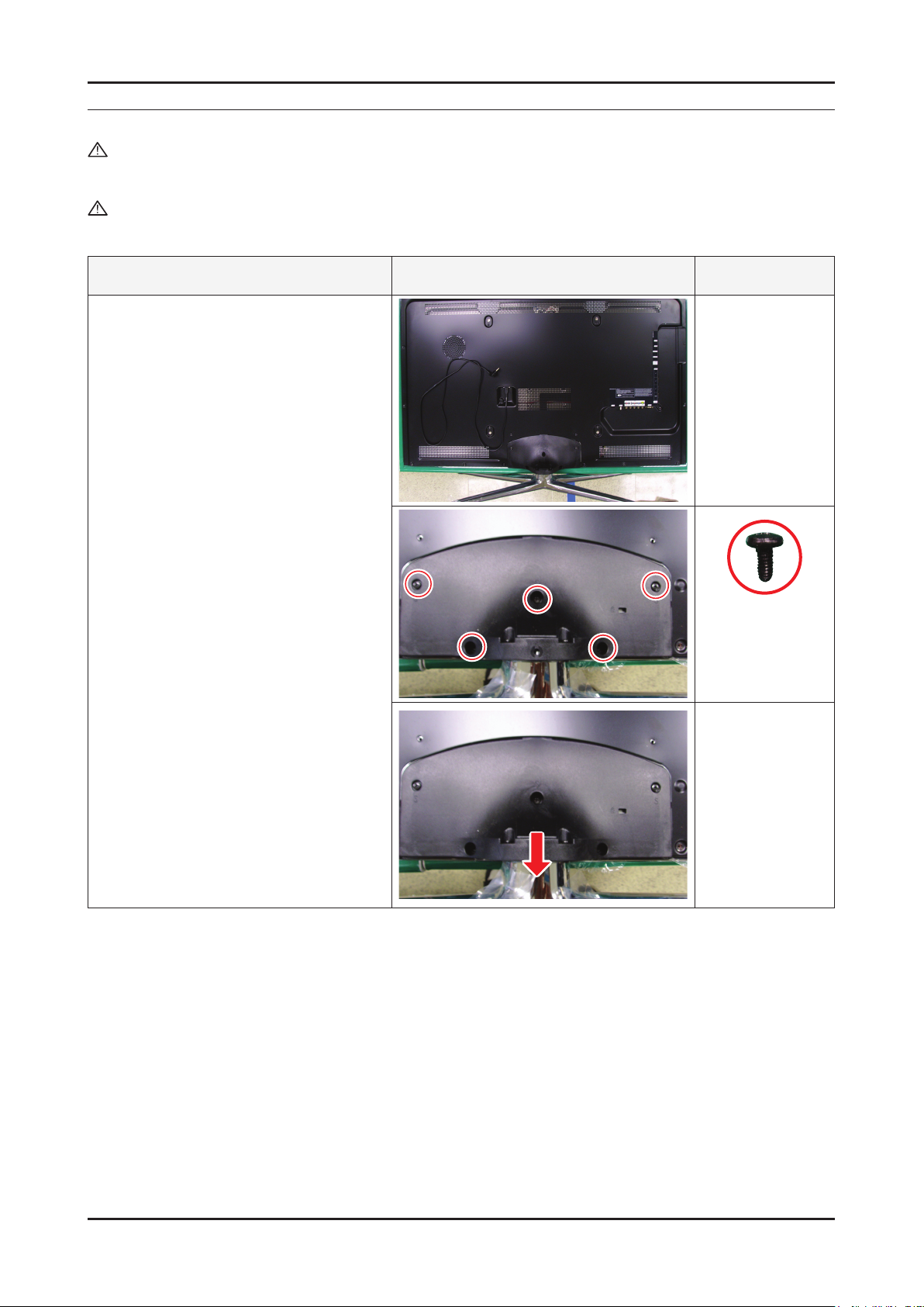
1. Place the TV face down on cushioned
table.Remove 4 screws from the Stand.
Remove stand.
6003-000133
(M4, L8, MACHINE)
3-1
Page 5

3-2
3. Disassembly and Reassemble
Description Picture Description Screws
2. Remove the screws of rear-cover.
2-1. Pull out a AC Power Cord
6003-000133
(M4, L8, MACHINE)
6003-001003
(M4, L12, TAPTYPE)
3. Lift up the rear-cover.
Page 6

3-3
3. Disassembly and Reassemble
Description Picture Description Screws
4. Remove the cables and screws from
SMPS, Main board and Woofer and
Bracket stand link.
46 inch
55 inch
6001-002283
(M3, L5, MACHINE)
6003-000133
(M4, L8, MACHINE)
Page 7
3. Disassembly and Reassemble
Description Picture Description Screws
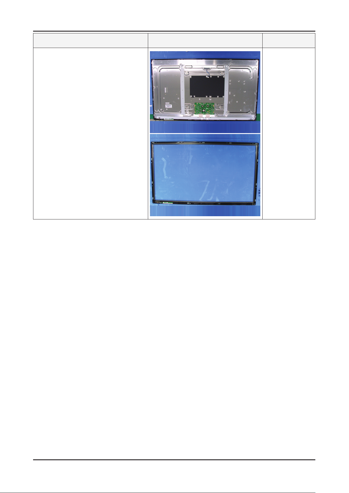
5. Lift up the panel so you can remove front
cover.
Reassembly procedures are in the reverse order of disassembly procedures. ※
3-4
Page 8

5. Exploded View & Part List
F001A
PA NEL
R001A
SB04A
SB05A
CB01
M0014
T0175
T0920
T0176
T0176
5-1. UE46C6990VS Exploded View
5. Exploded View & Part List
5-1-1. UE46C6990VS Parts List
Location No. Code No. Description & Specication Q’ty SA/SNA Remark
F001A BN96-13748C ASSY COVER P-FRONT;UC6900 46,EO,PC+PC,V0 1 SA
T0176 BN96-12941D ASSY SPEAKER P;8ohm,4pin,10,L:440 R:810, 1 SA
PANEL BN07-00877A LCD-PANEL;LTF460HJ04,SSEZJW,8bit,46,16.7 1 SA
CB01 BN61-04924A BRACKET-AV;LB700 40,PCM,T0.5,BKN-P824, P 1 SNA
SB05A BN96-12929E ASSY BRACKET P-STAND LINK;UC6500,46,SECC 1 SNA
T0175 BN96-12965A ASSY SPEAKER P;4ohm,4pin,20W,R: 680,Encl 1 SA
M0014 BN94-03767B ASSY PCB MAIN;UE46C6900VSXXC 1 SA
R001A BN96-13843B ASSY COVER P-REAR;UC6900 46,EO,PCM,BKN-P 1 SA
T0920 BN61-06221A GUIDE-STAND;UC6500 40inch,PC,G/F 20%,V2, 1 SNA
SB04A BN96-13133E ASSY STAND P-BASE;46/55,FOUR-LEG,PC+ABS, 1 SA
5-1
Page 9

5-2
5. Exploded View & Part List
5-2. UE46C6990VS Parts List
Service Bom (SA: SERVICE AVAILABLE, SNA: SERVICE NOT AVAILABLE)
Level Location No. Code No. Description & Specication Q’ty SA/SNA Remark
UE46C6990VSXZG
0.1 S001A BN90-02594K ASSY STAND;UC7000 46/55 1 SNA
..2 SC02A BN96-13131G ASSY COVER P-GUIDE STAND;UC7000,PC+ABS G 1 SA
...3 T0524 6902-001063 BAG PE;LDPE,T0.05,W180,L350,TRP,RECYCLE 1 SNA
...3 T0920 BN61-06221A GUIDE-STAND;UC6500 40inch,PC,G/F 20%,V2, 1 SNA
....4 0103-007285 RESIN-PC;MW32020GFU,BK0007,2.0 V2,PC/GF2 450 SNA
...3 T0527 BN68-00513A LABEL-E,PASS;ALL MODEL,YUPO(110G),50X15, 1 SNA
...3 BN68-02825B MANUAL FLYER-01,STAND GUIDE;7~9 series,S 1 SNA
...3 BN96-12031N ASSY ACCESSORY-SCREW;10 LEDTV(40/46/55), 1 SNA
....4 M0081 6003-000133 SCREW-TAPTYPE;BH,+,-,S,M4,L8,ZPC(BLK),SW 9 SA
....4 BN69-04419L PACKING-BAG PE;UC5000,LDPE,70,90,4X8, 9E 1 SNA
..2 SB04A BN96-13133E ASSY STAND P-BASE;46/55,FOUR-LEG,PC+ABS, 1 SA
...3 M0081 6003-001003 SCREW-TAPTYPE;BH,+,B,M4,L12,ZPC(BLK),SWR 13 SA
...3 SCREW 6003-001785 SCREW-TAPTYPE;FH,+,B,M4,L8,ZPC(BLK),SWRC 4 SA
...3 BN61-05240A HOLDER-SWIVEL RING TOP;LB700 46,POM HB,A 1 SNA
...3 AB323 BN61-06196A BRACKET-STAND;46,55 FOUR-LEG,ALDC12,ALDC 1 SNA
...3 BN61-06200A BRACKET-STAND, FRONT;46,55 FOUR-LEG,HGI, 2 SNA
...3 BN61-06204A BRACKET-STAND, REAR;46,55 FOUR-LEG,HGI,T 2 SNA
...3 BN61-06331A HOLDER-SWIVEL RING BOTTOM;UC7K 46/55,POM 1 SNA
...3 BN63-06582E COVER-STAND, BASE;46/55,FOUR-LEG,ABS+PC, 1 SNA
....4 0103-007489 RESIN-HIPS;FT875,BK,BK0020,V1,HIPS 180 SNA
...3 T0527 BN68-00513A LABEL-E,PASS;ALL MODEL,YUPO(110G),50X15, 1 SNA
...3 M0126 BN73-00052E RUBBER-FOOT;4-LEG,CR RUBBER,T1.5 DIA17,R 4 SNA
...3 BN74-00031A GREASE;kanto-kasei FL-955,grease,wht 0.6 SNA
...3 BN63-06574B COVER-STAND REAR,R;46/55,FOUR-LEG,ABS+PC 1 SNA
...3 BN63-06575B COVER-STAND REAR,L;46/55,FOUR-LEG,ABS+PC 1 SNA
...3 BN63-06946B COVER-STAND FRONT;46/55,FOUR-LEG,ABS+PC, 1 SNA
...3 BN96-13563A ASSY BRACKET P-SWIVEL BOT;4-LEG(55),BRKT 1 SNA
....4 BN61-02428Q STUD-PEM;PNA,M4,D7,L9.3,ZPC(SIL),SUM24L 4 SNA
....4 BN61-06269A BRACKET-SWIVEL BOT;SPC,T 3.0,Zn-Plating, 1 SNA
...3 BN61-06268A BRACKET-SWIVEL TOP;SPC,T 3.0,Zn-Plating, 1 SNA
...3 T0382 BP61-00495C HOLDER-CARE;PJT,ACRYL-FOAM,T0.25,W30.0mm 0.18 SNA
...3 CCM1 BN63-05199D COVER-SHEET;AMBER,PE,T0.08,W75mm,200M,CL 2 SNA
0.1 BN90-02698C ASSY COVER FRONT;UC6900 46 1 SNA
..2 F001A BN96-13748C ASSY COVER P-FRONT;UC6900 46,EO,PC+PC,V0 1 SA
...3 M0081 6003-001003 SCREW-TAPTYPE;BH,+,B,M4,L12,ZPC(BLK),SWR 1 SA
...3 BN60-00162Z SPACER-FOAM;FOAM,50000mm,Dark Gray,0.35T 1 SNA
...3 BN61-05728C BOSS-TAPE;UB7000,acryl,T0.4,W16,DARK GRA 2.3 SNA
...3 BN61-05728E BOSS-TAPE;UB7000,acryl,T0.4,W25,DARK GRA 0.9 SNA
...3 BN61-06213A BRACKET-STOPPER BOSS;C8K,S50C+SECC T1.2 11 SNA
...3 BN61-06510A BOSS-TAPE;UC8000,acryl,T1.5,W10,white 0.07 SNA
...3 BN61-06660A BOSS-BOND;UC6900/8000,EPOXY,GREEN 1.2 SNA
...3 F001 BN63-06628B COVER-FRONT;UC6900/8000 46,EO,PC+PC,V0,T 1 SNA
....4 0103-007268 RESIN-PC;TP0010,2.0V0,NH PC,NH PC 2.0 V2 1,220.00 SNA
....4 0103-007269 RESIN-PC;GY0132,2.0V0,NH PC,NH PC 2.0 V2 1,020.00 SNA
Page 10

5-3
5. Exploded View & Part List
Level Location No. Code No. Description & Specication Q’ty SA/SNA Remark
...3 AC280 BN63-06767A COVER-PCB;UC8K,HIPS,V0, BLK 1 SNA
....4 0103-004637 RESIN-HIPS;BK0020,V0,HIPS,NoN-Deca,NoN-D 24 SNA
...3 BN63-06770C COVER-MASK;UC6900 46,EO,PC+ABS,V0,BK0008 1 SNA
....4 0103-005041 RESIN-PC;V0,PC+ABS 540 SNA
...3 BN63-07229A COVER-SHEET;rose70",urethane,T0.052,W50m 3 SNA
...3 BN63-07229C COVER-SHEET;rose70",urethane,T0.052,W70m 1.3 SNA
...3 BN68-02700A LABEL-LED-POP;Highlight Sticker Color,PE 1 SNA
...3 M0125 BN96-13679D ASSY BOARD P-TOUCH FUNCTION&IR;LC6500,CT 1 SA
...3 CW01A BN96-13996A ASSY COVER P-WINDOW-RMC LED;UC6900 40/46 1 SNA
....4 BN61-06539A BOSS-TAPE;UC8000,PE,T0.16,W5,Transparent 0.01 SNA
....4 T0299 BN64-01346A WINDOW-RMC LED;UC6900(MOLD),PC,V2,violle 1 SNA
...3 T0382 BP61-00495C HOLDER-CARE;PJT,ACRYL-FOAM,T0.25,W30.0mm 0.08 SNA
...3 BN60-00162E SPACER-FOAM;FOAM,50000mm,Dark Gray,0.5T, 0.05 SNA
...3 CIS1 0203-001598 TAPE-FILAMENT;#8915,0.15,12,55000,CLR 0.2 SNA
...3 CCM1 BN63-02183E COVER-SHEET;Rhcm,PE Vinyl,T0.04,750mm,20 1.7 SNA
...3 T0176 BN96-12941D ASSY SPEAKER P;8ohm,4pin,10,L:440 R:810, 1 SA
0.1 R001A BN90-02701B ASSY COVER REAR;UC6900 46 1 SNA
..2 R001A BN96-13843B ASSY COVER P-REAR;UC6900 46,EO,PCM,BKN-P 1 SA
...3 T0069 BN60-00121A SPACER-FELT;UB7000,FELT,L380,BLK,T0.35,W 2 SNA
...3 R001 BN63-06605B COVER-REAR;UC6900 46,EO,PCM,BKN-P824 1 SNA
...3 BN68-02543E LABEL-TERMINAL BOTTOM;Rev.02 UC6000,EO,P 1 SNA
...3 BN68-02544B LABEL-TERMINAL SIDE;Rev.01 UC5000/6000,E 1 SNA
...3 BN96-13845A ASSY MISC P-INSULATOR;UC6900,PC,T0.43 1 SNA
....4 T0278 BN60-00124A SPACER-SPONGE;UB7000,CR,L310,T2.0,W10 2 SNA
....4 BN63-07083A SHEET-INSULATOR SMPS;UC6900 40/46/55inch 1 SNA
...3 BN61-04692A BOSS-PRIMER;#94,clear,35cps 0.001 SNA
...3 BN60-00162Y SPACER-FOAM;FOAM,50000mm,Dark Gray,0.35T 0.45 SNA
..2 T0382 BP61-00495C HOLDER-CARE;PJT,ACRYL-FOAM,T0.25,W30.0mm 0.1 SNA
0.1 BN91-05636A ASSY LCD-AMLCD;BN07-00877A 1 SNA
..2 PANEL BN07-00877A LCD-PANEL;LTF460HJ04,SSEZJW,8bit,46,16.7 1 SA
...3 TCON BN81-04401A A/S-T CON LTF460HJ04;LTF460HJ04 1 SA
0.1 M0017 BN91-05840B ASSY CHASSIS;UE46C6900VSXXC 1 SNA
..2 M0014 BN94-03767B ASSY PCB MAIN;UE46C6900VSXXC 1 SA
...3 0202-001608 SOLDER-WIRE FLUX;LFC7-107,D0.8,99.3Sn/0. 0.25 SNA
...3 CB01 BN61-04924A BRACKET-AV;LB700 40,PCM,T0.5,BKN-P824, P 1 SNA
...3 T0066 BN62-00071A HEAT SINK-ES;22*22*2.5,Ceramic,T2.6,TAPE 3 SNA
...3 T0066 BN62-00072A HEAT SINK-ES;40*40*2.5,Ceramic,T2.6,TAPE 1 SNA
...3 BN97-04550B ASSY SMD;UE46C6900VSXXC,BN94-03767A 1 SNA
....4 DS01A 0401-000116 DIODE-SWITCHING;MMSD914T1,100V,200mA,SOD 2 SA
....4 DS01A 0401-001056 DIODE-SWITCHING;MMBD4148SE,100V,200mA,SO 16 SA
....4 0403-001164 DIODE-ZENER;MMSZ5232B,5.32-5.88V,500MW,S 1 SA
....4 0403-001783 DIODE-ZENER;BZB84-C6V2,5.8/6.6V,300mW,SO 19 SNA
....4 D0254 0404-001271 DIODE-SCHOTTKY;SSA34,40V,3000mA,SMA,TP 4 SA
....4 D0254 0404-001404 DIODE-SCHOTTKY;BAT721C,40V,200mA,SOT-23, 8 SA
....4 T0139 0406-001200 DIODE-TVS;RCLAMP0504F,6/-/-V,150W,SC-70 2 SA
....4 T0139 0406-001271 DIODE-TVS;RCLAMP0524P,6/-/-V,150W,SLP251 8 SNA
....4 SD3 0407-000114 DIODE-SWITCHING;KDS184,80V,100mA,SOT-23, 1 SNA
....4 Q101 0501-000445 TR-SMALL SIGNAL;KTC3875S-Y,NPN,150mW,SOT 14 SA
....4 0501-000669 TR-SMALL SIGNAL;KTA1505Y,PNP,150mW,SOT-2 2 SA
Page 11

5-4
5. Exploded View & Part List
Level Location No. Code No. Description & Specication Q’ty SA/SNA Remark
....4 CEQ2 0505-000110 FET-SILICON;2N7002,N,60V,115mA,7.5ohm,0. 2 SA
....4 Q409 0505-000274 FET-SILICON;AO4435L,P,-30V,-11A,0.014ohm 1 SNA
....4 Q409 0505-002386 FET-SILICON;AO3415AL,P,-20V,-4A,0.045ohm 2 SA
....4 IC104 0801-002630 IC-CMOS LOGIC;74AHCT1G08,2-INPUT AND GAT 1 SA
....4 ND51C2 0801-002780 IC-CMOS LOGIC;74LVC1G17,SCHMITT-TRIGGER 1 SA
....4 IC104 0801-003330 IC-CMOS LOGIC;Octal buffer,DQFN,20P,4.5x 5 SA
....4 IC104 0802-001012 IC-CMOS LOGIC;74LCX245,TRANSCEIVER,DQFN, 1 SNA
....4 1001-000164 IC-ANALOG MULTIPLEX;74HC4052,CMOS,SOP,16 1 SA
....4 IC106 1001-001573 IC-VIDEO SWITCH;SiI9287BCNUTR,QFN,72P,10 1 SNA
....4 IC112 1103-000129 IC-EEPROM;24C02,2Kbit,256x8,SOP,8P,5x4mm 1 SA
....4 IC112 1103-001310 IC-EEPROM;24LC02B,256X8BIT,SOIC,8P,3.91X 1 SNA
....4 IC112 1103-001475 IC-EEPROM;M24256-BR,256Kbit,32Kx8,SOP,8P 2 SNA
....4 T0085 1201-002487 IC-AUDIO AMP;MAX9728A,QFN,12P,3x3mm,DUAL 1 SA
....4 T0124 1201-002992 IC-POWER AMP;STA369BWS,PSSO,36P,10.3x7.5 2 SA
....4 T0087 1203-002519 IC-POSI.FIXED REG.;KIA7809AF,DPAK,3P,240 1 SA
....4 IC012 1203-003544 IC-POSI.ADJUST REG.;RT9173BPS,SOP-8,8P,5 1 SA
....4 1203-004363 IC-VOL. DETECTOR;RT9818C-29PV,SOT-23,3P, 1 SA
....4 1203-004364 IC-VOL. DETECTOR;RT9818C-42PV,SOT-23,3P, 1 SA
....4 1203-005538 IC-DC/DC CONVERTER;AOZ1021HAIL,SOP,8P,4. 3 SA
....4 1203-005663 IC-DC/DC CONVERTER;LNBH23QTR,QFN,32P,5x5 1 SA
....4 IC012 1203-005756 IC-POSI.ADJUST REG.;AP7173-SP,SOP-8L-EP, 1 SA
....4 1203-006012 IC-DC/DC CONVERTER;MP8725EL,QFN14,14P,3x 1 SA
....4 T0087 1203-006109 IC-POSI.FIXED REG.;S-1206B33-M3T1G,SOT-2 1 SA
....4 IC012 1203-006138 IC-POSI.ADJUST REG.;AP1117DGZ-13-89,TO-2 1 SA
....4 T0087 1203-006141 IC-POSI.FIXED REG.;S-1172B33-U5T1G,SOT-8 3 SA
....4 1203-006142 IC-DC/DC CONVERTER;BD8924G,5P,2.9x1.6x1. 1 SA
....4 1203-006167 IC-POSI.FIXED REG.;S-1172B12-U5T1G,SOT-8 1 SA
....4 IC118 1204-003085 IC-VIDEO PROCESS;SDP91-PS,PBGA,496P,23x2 1 SA
....4 1204-003100 IC-DECODER;SDP92,FCPBGAH,937P,35x35mm,PL 1 SA
....4 IC118 1204-003101 IC-VIDEO PROCESS;SDP94,PBGA,345P,19x19mm 1 SNA
....4 1205-003201 IC-BUS SWITCH;TC7WB125FK,SSOP,8P,2x2.3mm 3 SA
....4 1205-003479 IC-SWITCH;TPS2051BDBVR,SOT-23,5P,2.9x1.6 1 SA
....4 1205-003733 IC-SWITCH;AP2191MPG-13,MSOP-8L-EP,8P,2.9 1 SA
....4 1205-003735 IC-SWITCH;AP2151WG-7,SOT25,5P,2.9x1.6mm, 1 SA
....4 1205-003834 IC-ETHERNET CONTROLLER;RTL8201E-VC-GR,QF 1 SA
....4 1205-003840 IC-CODEC;WM8595GEFL/RS,QFN,48P,7x7x0.9mm 1 SA
....4 1405-001185 VARISTOR;24Vdc,1.6x0.8x0.36mm,TP 1 SA
....4 1405-001233 VARISTOR;30Vdc,5A,1.6x0.8x0.8mm,TP 28 SA
....4 PR6 2007-000072 R-CHIP;47ohm,5%,1/10W,TP,1608 6 SNA
....4 MR604 2007-000137 R-CHIP;2Kohm,5%,1/16W,TP,1005 14 SNA
....4 R105 2007-000138 R-CHIP;100ohm,5%,1/16W,TP,1005 39 SA
....4 HDR7 2007-000139 R-CHIP;220ohm,5%,1/16W,TP,1005 1 SNA
....4 AR49 2007-000140 R-CHIP;1Kohm,5%,1/16W,TP,1005 27 SNA
....4 MR306 2007-000141 R-CHIP;2.2Kohm,5%,1/16W,TP,1005 5 SNA
....4 R319 2007-000143 R-CHIP;4.7Kohm,5%,1/16W,TP,1005 56 SNA
....4 2007-000146 R-CHIP;6.8Kohm,5%,1/16W,TP,1005 1 SNA
....4 R104 2007-000148 R-CHIP;10Kohm,5%,1/16W,TP,1005 28 SA
....4 R102 2007-000149 R-CHIP;12Kohm,5%,1/16W,TP,1005 1 SA
....4 RR33 2007-000154 R-CHIP;24Kohm,5%,1/16W,TP,1005 1 SA
Page 12

5-5
5. Exploded View & Part List
Level Location No. Code No. Description & Specication Q’ty SA/SNA Remark
....4 AR43 2007-000155 R-CHIP;27Kohm,5%,1/16W,TP,1005 1 SNA
....4 MR13 2007-000157 R-CHIP;47Kohm,5%,1/16W,TP,1005 16 SNA
....4 DR39 2007-000162 R-CHIP;100Kohm,5%,1/16W,TP,1005 8 SNA
....4 R509 2007-000170 R-CHIP;1Mohm,5%,1/16W,TP,1005 4 SNA
....4 R111 2007-000171 R-CHIP;0ohm,5%,1/16W,TP,1005 40 SNA
....4 HDR17 2007-000172 R-CHIP;10ohm,5%,1/16W,TP,1005 6 SNA
....4 R338 2007-000173 R-CHIP;22ohm,5%,1/16W,TP,1005 44 SNA
....4 UR23 2007-000174 R-CHIP;47ohm,5%,1/16W,TP,1005 16 SNA
....4 2007-000231 R-CHIP;1.3Kohm,1%,1/10W,TP,1608 2 SA
....4 MR39 2007-000242 R-CHIP;1.5Kohm,5%,1/16W,TP,1005 1 SNA
....4 UR53 2007-000305 R-CHIP;10Mohm,5%,1/10W,TP,1608 1 SA
....4 HR12 2007-000591 R-CHIP;22ohm,1%,1/10W,TP,1608 1 SNA
....4 2007-000606 R-CHIP;240ohm,1%,1/10W,TP,1608 2 SA
....4 JR11 2007-000614 R-CHIP;24Kohm,1%,1/10W,TP,1608 2 SNA
....4 KAR28 2007-000637 R-CHIP;270Kohm,5%,1/10W,TP,1608 1 SNA
....4 R945 2007-000726 R-CHIP;300ohm,1%,1/10W,TP,1608 1 SA
....4 R19 2007-000763 R-CHIP;330ohm,1%,1/10W,TP,1608 1 SNA
....4 R528 2007-000835 R-CHIP;39ohm,1%,1/10W,TP,1608 1 SA
....4 DR37 2007-000932 R-CHIP;470ohm,5%,1/16W,TP,1005 4 SNA
....4 R740 2007-001217 R-CHIP;82ohm,5%,1/16W,TP,1005 1 SNA
....4 OTR1 2007-001292 R-CHIP;33ohm,5%,1/16W,TP,1005 6 SNA
....4 DR43 2007-001298 R-CHIP;51ohm,5%,1/16W,TP,1005 1 SNA
....4 CER07 2007-001308 R-CHIP;200ohm,5%,1/16W,TP,1005 3 SNA
....4 R326 2007-001325 R-CHIP;3.3Kohm,5%,1/16W,TP,1005 6 SNA
....4 2007-001333 R-CHIP;18Kohm,5%,1/16W,TP,1005 1 SNA
....4 2007-001335 R-CHIP;36Kohm,5%,1/16W,TP,1005 2 SA
....4 MR316 2007-002796 R-CHIP;510ohm,5%,1/16W,TP,1005 1 SA
....4 PR24 2007-002970 R-CHIP;56ohm,5%,1/16W,TP,1005 2 SA
....4 AVR22 2007-003013 R-CHIP;2.4Kohm,5%,1/16W,TP,1005 1 SNA
....4 2007-003022 R-CHIP;62ohm,5%,1/16W,TP,1005 17 SNA
....4 R133 2007-007004 R-CHIP;12Kohm,1%,1/10W,TP,1608 1 SA
....4 2007-007008 R-CHIP;300ohm,5%,1/16W,TP,1005 1 SNA
....4 TR30 2007-007009 R-CHIP;75ohm,5%,1/16W,TP,1005 4 SA
....4 PR8 2007-007015 R-CHIP;13Kohm,5%,1/16W,TP,1005 1 SNA
....4 R365 2007-007107 R-CHIP;100Kohm,1%,1/16W,TP,1005 3 SNA
....4 2007-007132 R-CHIP;15Kohm,1%,1/16W,TP,1005 1 SA
....4 2007-007134 R-CHIP;39Kohm,1%,1/16W,TP,1005 1 SA
....4 2007-007136 R-CHIP;4.7Kohm,1%,1/16W,TP,1005 7 SNA
....4 2007-007137 R-CHIP;1.2Kohm,1%,1/16W,TP,1005 1 SA
....4 2007-007138 R-CHIP;27Kohm,1%,1/16W,TP,1005 2 SNA
....4 2007-007139 R-CHIP;47Kohm,1%,1/16W,TP,1005 2 SA
....4 DR4 2007-007142 R-CHIP;10Kohm,1%,1/16W,TP,1005 10 SNA
....4 2007-007156 R-CHIP;1ohm,5%,1/16W,TP,1005 5 SNA
....4 2007-007197 R-CHIP;3.3ohm,5%,1/16W,TP,1005 2 SNA
....4 2007-007306 R-CHIP;100ohm,1%,1/16W,TP,1005 17 SNA
....4 2007-007318 R-CHIP;1Kohm,1%,1/16W,TP,1005 32 SNA
....4 2007-007352 R-CHIP;130Kohm,1%,1/10W,TP,1608 1 SA
....4 2007-007469 R-CHIP;110ohm,1%,1/16W,TP,1005 1 SNA
....4 HDR44 2007-007470 R-CHIP;7.5Kohm,1%,1/16W,TP,1005 2 SNA
Page 13

5-6
5. Exploded View & Part List
Level Location No. Code No. Description & Specication Q’ty SA/SNA Remark
....4 2007-007617 R-CHIP;2.49Kohm,1%,1/10W,TP,1608 1 SA
....4 2007-007697 R-CHIP;2.4Kohm,1%,1/16W,TP,1005 1 SNA
....4 2007-007698 R-CHIP;5.1Kohm,1%,1/16W,TP,1005 2 SNA
....4 2007-007724 R-CHIP;40.2ohm,1%,1/10W,TP,1608 2 SA
....4 2007-007730 R-CHIP;6.8Mohm,1%,1/10W,TP,1608 1 SA
....4 2007-007766 R-CHIP;2Kohm,1%,1/16W,TP,1005 4 SNA
....4 2007-007947 R-CHIP;36ohm,1%,1/10W,TP,1608 1 SA
....4 MR11 2007-008015 R-CHIP;75ohm,1%,1/16W,TP,1005 24 SNA
....4 2007-008263 R-CHIP;3Kohm,1%,1/16W,TP,1005 1 SA
....4 2007-008275 R-CHIP;30Kohm,1%,1/16W,TP,1005 1 SNA
....4 2007-008391 R-CHIP;6.34Kohm,1%,1/16W,TP,1005 1 SA
....4 2007-008811 R-CHIP;1.5ohm,5%,1/16W,TP,1005 1 SA
....4 2007-009853 R-CHIP;1.6Kohm,1%,1/16W,TP,1005 1 SNA
....4 2011-001015 R-NETWORK;1Kohm,5%,1/16W,L,CHIP,8P,TP,3. 4 SC
....4 MR38 2011-001093 R-NETWORK;100ohm,5%,1/16W,L,CHIP,8P,TP,3 1 SA
....4 ZRN10 2011-001261 R-NETWORK;33ohm,5%,1/16W,L,CHIP,8P,TP,2. 5 SA
....4 DAR09 2011-001262 R-NETWORK;22ohm,5%,1/16W,L,CHIP,8P,TP,2. 25 SA
....4 2011-001264 R-NETWORK;10ohm,5%,1/16W,L,CHIP,8P,TP,2. 6 SNA
....4 2011-001345 R-NETWORK;10Kohm,5%,1/16W,L,CHIP,8P,TP,2 2 SA
....4 DRP29 2011-001396 R-NETWORK;4.7Kohm,5%,1/16W,L,CHIP,8P,TP, 1 SA
....4 2011-001427 R-NETWORK;0ohm,5%,1/16W,L,CHIP,8P,TP,2.0 2 SA
....4 2011-001449 R-NETWORK;22ohm,5%,1/16W,L,4P,TP,1010 7 SA
....4 2011-001497 R-NETWORK;470ohm,5%,1/16W,L,CHIP,4P,TP,1 2 SNA
....4 2011-001587 R-NETWORK;100ohm,5%,1/16W,L,CHIP-V,4P,TP 1 SNA
....4 C24 2203-000041 C-CER,CHIP;.01nF,0.25pF,50V,C0G,TP,1608 1 SA
....4 AC1 2203-000125 C-CER,CHIP;1.2nF,10%,50V,X7R,TP,1608,- 6 SA
....4 PC43 2203-000233 C-CER,CHIP;0.1nF,5%,50V,C0G,TP,1005 18 SA
....4 MC2 2203-000254 C-CER,CHIP;10nF,10%,16V,X7R,TP,1005 6 SA
....4 C134 2203-000257 C-CER,CHIP;10nF,10%,50V,X7R,TP,1608 1 SA
....4 DC54 2203-000278 C-CER,CHIP;.01nF,0.5pF,50V,C0G,TP,1005 3 SA
....4 RC34 2203-000280 C-CER,CHIP;0.01nF,0.5pF,50V,C0G,1608 3 SA
....4 C3 2203-000384 C-CER,CHIP;0.015nF,5%,50V,C0G,1608 2 SNA
....4 C304 2203-000405 C-CER,CHIP;0.18nF,5%,50V,C0G,1608 1 SNA
....4 MC302 2203-000425 C-CER,CHIP;.018nF,5%,50V,C0G,TP,1005 8 SA
....4 C254 2203-000438 C-CER,CHIP;1nF,10%,50V,X7R,TP,1005 14 SA
....4 C507 2203-000489 C-CER,CHIP;2.2nF,10%,50V,X7R,TP,1005 3 SA
....4 V1233 2203-000575 C-CER,CHIP;220nF,10%,25V,X7R,TP,2012 2 SNA
....4 AD480 2203-000585 C-CER,CHIP;0.22nF,10%,50V,X7R,1005 1 SA
....4 ZC14 2203-000626 C-CER,CHIP;0.022nF,5%,50V,C0G,1608 2 SNA
....4 AD480 2203-000679 C-CER,CHIP;0.027nF,5%,50V,C0G,1005 1 SA
....4 AD480 2203-000714 C-CER,CHIP;3.3nF,10%,50V,X7R,TP,1005,- 1 SA
....4 DC25 2203-000812 C-CER,CHIP;.033nF,5%,50V,C0G,TP,1005 9 SA
....4 CK40B 2203-000838 C-CER,CHIP;0.39NF,5%,50V,C0G,TP,1608 3 SNA
....4 C132 2203-000854 C-CER,CHIP;0.039nF,5%,50V,C0G,1005 4 SA
....4 AD480 2203-000995 C-CER,CHIP;.047nF,5%,50V,C0G,TP,1005 3 SA
....4 AC124 2203-000998 C-CER,CHIP;0.047nF,5%,50V,C0G,1608 2 SNA
....4 HDC5 2203-001072 C-CER,CHIP;0.056nF,5%,50V,NP0,1005 1 SA
....4 C101 2203-001124 C-CER,CHIP;.68nF,10%,50V,X7R,1005 1 SA
....4 KAC5 2203-001126 C-CER,CHIP;0.68nF,10%,50V,X7R,1608 2 SNA
Page 14

5-7
5. Exploded View & Part List
Level Location No. Code No. Description & Specication Q’ty SA/SNA Remark
....4 AD480 2203-001428 C-CER,CHIP;470nF,10%,50V,X7R,TP,2012 1 SNA
....4 AD480 2203-001851 C-CER,CHIP;0.016nF,5%,50V,NP0,TP,1608 2 SNA
....4 AD480 2203-002285 C-CER,CHIP;10nF,10%,50V,X7R,1005 18 SNA
....4 AVC08 2203-002398 C-CER,CHIP;22nF,10%,50V,X7R,1608 10 SNA
....4 AD480 2203-002525 C-CER,CHIP;0.56nF,10%,50V,X7R,TP,1005 1 SNA
....4 AD480 2203-002720 C-CER,CHIP;10nF,10%,25V,X7R,TP,1005 2 SNA
....4 C711 2203-002982 C-CER,CHIP;6.8nF,10%,50V,X7R,1005 1 SA
....4 AD480 2203-005054 C-CER,CHIP;0.0047nF,0.25pF,50V,NP0,TP,10 3 SA
....4 DC18 2203-005138 C-CER,CHIP;1.8nF,10%,50V,X7R,1005 6 SA
....4 AAC1 2203-005249 C-CER,CHIP;100nF,10%,50V,X7R,TP,1608 35 SNA
....4 AD480 2203-005344 C-CER,CHIP;22nF,10%,25V,X7R,TP,1005,- 11 SNA
....4 AD480 2203-005393 C-CER,CHIP;.005nF,0.1pF,50V,NP0,TP,1005 2 SNA
....4 AD480 2203-005533 C-CER,CHIP;1000nF,20%,6.3V,X7R,TP,1608 2 SNA
....4 PC8 2203-005642 C-CER,CHIP;0.22nF,5%,50V,NP0,1005 1 SNA
....4 AD480 2203-005968 C-CER,CHIP;4.7NF,10%,50V,X7R,TP,1005 3 SNA
....4 AD480 2203-006039 C-CER,CHIP;1nF,10%,2000V,X7R,3216 1 SA
....4 AD480 2203-006104 C-CER,CHIP;1000nF,10%,50V,X7R,TP,3225,2. 1 SA
....4 AD480 2203-006126 C-CER,CHIP;47nF,10%,16V,X7R,TP,1005 3 SNA
....4 PC11 2203-006141 C-CER,CHIP;1000nF,10%,16V,X5R,1608 3 SNA
....4 C102 2203-006158 C-CER,CHIP;100nF,10%,16V,X7R,TP,1005 270 SNA
....4 AD480 2203-006307 C-CER,CHIP;1000nF,10%,25V,X5R,2012 1 SNA
....4 AD480 2203-006333 C-CER,CHIP;10000nF,20%,16V,X5R,TP,3216 10 SNA
....4 AD480 2203-006336 C-CER,CHIP;10000nF,10%,25V,X5R,3216 11 SA
....4 C125 2203-006361 C-CER,CHIP;10000nF,10%,10V,X5R,TP,2012 4 SC
....4 HE4 2203-006474 C-CER,CHIP;22000nF,20%,6.3V,X5R,2012 12 SA
....4 HDC11 2203-006562 C-CER,CHIP;1000nF,10%,10V,X5R,TP,1005 26 SNA
....4 AD480 2203-006636 C-CER,CHIP;220nF,10%,25V,X7R,TP,1608 9 SA
....4 AD480 2203-006824 C-CER,CHIP;4700nF,10%,10V,X5R,1608 4 SNA
....4 AD480 2203-006992 C-CER,CHIP;0.33nF,5%,50V,C0G,TP,1005 2 SNA
....4 AD480 2203-007176 C-CER,CHIP;10000nF,10%,16V,X5R,TP,2012 2 SNA
....4 AD480 2203-007233 C-CER,CHIP;22000nF,10%,16V,X5R,TP,3216 2 SA
....4 AD480 2203-007270 C-CER,CHIP;10000nF,10%,10V,X5R,TP,1608 98 SNA
....4 C 2402-001254 C-AL,SMD;10uF,20%,50V,WT,TP,6.3x5.2mm 1 SA
....4 C 2402-001268 C-AL,SMD;100uF,20%,25V,WT,TP,8x6.3mm 3 SA
....4 2503-001051 C-NETWORK;100nFx4,20%,16V,2012 10 SA
....4 2601-001056 TRANS-SMD,PULSE;350UH,-,1:1,1:1,12.7X6.7 1 SA
....4 T0052 2703-000158 INDUCTOR-SMD;1uH,10%,2012 4 SA
....4 T0052 2703-000222 INDUCTOR-SMD;560nH,10%,2012 3 SA
....4 T0052 2703-000296 INDUCTOR-SMD;680nH,10%,1608 1 SA
....4 VL6 2703-000398 INDUCTOR-SMD;10uH,10%,3225 8 SA
....4 S1Q0361 2703-000408 INDUCTOR-SMD;3.3uH,20%,3225 1 SA
....4 T0052 2703-001239 INDUCTOR-SMD;3.3uH,10%,1608 1 SA
....4 T0052 2703-002238 INDUCTOR-SMD;1UH,5%,2012 2 SNA
....4 T0052 2703-002332 INDUCTOR-SMD;330nH,5%,1608 1 SA
....4 T0052 2703-002557 INDUCTOR-SMD;270NH,5%,1608 3 SNA
....4 T0052 2703-003150 INDUCTOR-SMD;4.7uH,20%,5050 4 SNA
....4 2703-003296 INDUCTOR-SMD;47uH,10%,2012 1 SNA
....4 T0052 2703-003559 INDUCTOR-SMD;4.7uH,20%,8080 4 SNA
....4 T0052 2703-003636 INDUCTOR-SMD;270uH,20%,10x10mm 1 SA
Page 15

5-8
5. Exploded View & Part List
Level Location No. Code No. Description & Specication Q’ty SA/SNA Remark
....4 T0052 2703-003637 INDUCTOR-SMD;22uH,20%,7070 1 SA
....4 T0052 2703-003713 INDUCTOR-SMD;1.5uH,20%,7366 2 SA
....4 X202 2801-003326 CRYSTAL-SMD;24MHz,30ppm,28-ABX,20pF,50oh 2 SA
....4 X202 2801-003773 CRYSTAL-SMD;12MHz,30ppm,28-AAN,20pF,50oh 1 SA
....4 X202 2801-003954 CRYSTAL-SMD;27MHz,30ppm,28-AAN,16pF,50oh 1 SA
....4 X202 2801-004629 CRYSTAL-SMD;27MHz,20ppm,12pF,50ohm,TP 1 SNA
....4 X202 2801-004734 CRYSTAL-SMD;25.000000MHz,20ppm,28-AAN,12 1 SA
....4 2804-001878 OSCILLATOR-CLOCK;49.152MHz,50ppm,10TTL/1 1 SA
....4 F103 2901-001506 FILTER-EMI SMD;5V,0.13A,0pF,2x1x0.5mm,TP 2 SA
....4 T0568 3301-001236 BEAD-SMD;60ohm,1608 14 SNA
....4 T0568 3301-001404 BEAD-SMD;30ohm,2012,TP,15.9OHM/30MHz 48 SA
....4 T0568 3301-002039 BEAD-SMD;26ohm,1608,TP 25 SA
....4 3701-001293 CONNECTOR-HDMI;19P,2R,FEMALE,SMD-A,AU 4 SA
....4 CN906 3707-001095 CONNECTOR-OPTICAL;SMD-A(Ultra Slim),SPDI 1 SA
....4 AC510 3708-002777 CONNECTOR-FPC/FFC/PIC;82P,0.5mm/0.75mm,S 1 SA
....4 3710-002276 SOCKET-INTERFACE;24P,1R,0.5mm,SMD-A,AU,B 1 SA
....4 3722-003044 JACK-USB;4P/1C,NI,BLK,SMD-A,A-TYPE 2 SA
....4 IC125 BN13-00032A IC ASIC;SPD96,PRSS001,144,1.62,-40 to +8 1 SA
....4 ET01 BN40-00175A TUNER;DNSS24CVH161A,DVB-T/C+S2,164CH,38. 1 SA
....4 BN41-01530A PCB MAIN;C6900 valencia eu,FR-4,4,1.2T,2 1 SNA
....4 BN97-04194A ASSY MICOM-MAIN;T-VALDEUC-2000.0,2010.08 1 SNA
.....5 1107-001868 IC-NAND FLASH;KFG8GH6U4M-AIB6,1GByte,512 1 SNA
....4 BN97-04244A ASSY MICOM-SUB;T-VAL8DEUS-1005,2010.04.2 1 SNA
.....5 IC520 0903-001651 IC-MICROCONTROLLER;61P802-RG480WT,LQFP,4 1 SNA
....4 1105-002127 IC-DDR2 SDRAM;K4T51163QI-HCE7,512Mbit,32 2 SA
....4 1105-002152 IC-DDR2 SDRAM;K4T1G084QF-BCF8,DDR2,1Gbit 4 SNA
....4 1105-002153 IC-DDR2 SDRAM;K4T1G164QF-BCF8,DDR2,1Gbit 2 SNA
....4 0202-001477 SOLDER-CREAM;LST309-M,D20~45um,96.5Sn/3A 4.852 SNA
....4 3709-001641 CONNECTOR-CARD SLOT;68P(U/SLIM 60mm) W/L 1 SNA
....4 3711-007569 CONNECTOR-HEADER;BOX,14P,2R,2.0mm,DIP,SN 1 SA
....4 3711-007583 CONNECTOR-HEADER;BOX,10P,1R,2.0mm,ANGLE- 1 SA
....4 3711-007585 CONNECTOR-HEADER;BOX,4P,1R,2.5mm,ANGLE-D 2 SA
....4 3711-007587 CONNECTOR-HEADER;BOX,18P,2R,2mm,ANGLE-DI 1 SA
....4 3722-003156 JACK-PHONE;1/7P,NI,LAUREL-GREEN,ANGLE 1 SA
....4 3722-003159 JACK-PHONE;1/7P,NI,YEL,ANGLE 1 SA
....4 3722-003158 JACK-PHONE;1/7P,NI,BLK,ANGLE 2 SA
....4 3701-001724 CONNECTOR-DSUB;15P,3ROW,FEMALE,ANGLE,NI 1 SA
....4 3722-003150 JACK-MODULAR;8P/8C(ULTRA SLIM),YES,ANGLE 1 SA
...3 BN97-04241A ASSY CI PLUS;BN46-00027A,platform Euro C 1 SNA
....4 BN46-00027A KEY CODE-CI PLUS;CI PLUS KEY,TCTC,SERIAL 1 SNA
0.1 BN91-05841A ASSY SHIELD;UE46C6900VSXXC 1 SNA
..2 CIS1 0203-001586 TAPE-FILAMENT;#893,0.15,30,55 0.2 SNA
..2 T0081 6001-000115 SCREW-MACHINE;BH,+,-,M3,L10,ZPC(WHT),SWR 2 SNA
..2 T0081 6001-002283 SCREW-MACHINE;BH,+,M3,L5,ZPC(WHT),SWRCH1 9 SNA
..2 T0081 6001-002610 SCREW-MACHINE;BH,+,M4,L6,ZPC(BLK),SWRCH1 12 SA
..2 SCREW 6003-001782 SCREW-TAPTYPE;BH,+,B,M4,L12,ZPC(BLK),SWR 18 SA
..2 EC13 BN39-01267W LEAD CONNECTOR;UN46C6800UFXZA,Lead Conne 1 SA
..2 M2893 BN39-01292A LEAD CONNECTOR;UE40B7700,Flat Connector 1 SA
..2 P001A BN44-00372A DC VSS-LED TV PD BD;PD46CF1E_ZSM,PSLF201 1 SA
Page 16

5-9
5. Exploded View & Part List
Level Location No. Code No. Description & Specication Q’ty SA/SNA Remark
..2 BN73-00273A SILICON/RUBBER-GAPPAD;UE46B7700,SILICON+ 1 SNA
..2 FL06 BN96-12723W ASSY CABLE P-FPCB LVDS;LED120Hz-46inch-6 1 SA
..2 T0175 BN96-12965A ASSY SPEAKER P;4ohm,4pin,20W,R: 680,Encl 1 SA
..2 CCMM1 BN73-00211B SILICON/RUBBER;UN46B9000XFXZA,SILICON+PO 1 SNA
..2 SB05A BN96-12929E ASSY BRACKET P-STAND LINK;UC6500,46,SECC 1 SNA
...3 BN60-00184A SPACER-FOAM;FOAM,30000mm,DARK GRAY,1T,30 0.19 SNA
...3 BN61-02932K BRACKET-STOPPER NUT;LED TV,M4,D6,L7.0,BR 5 SNA
...3 M0115 BN61-06167A BRACKET-STAND LINK;UC6500 46inch,HGI,T3. 1 SNA
0.1 BN92-05975A ASSY P/MATERIAL;UC6900 46 1 SNA
..2 6902-000379 BAG AIR;LDPE,T0.2,W1000,L1800,TRP,1260.0 1 SNA
..2 6902-001183 BAG PE;HDPE/NITRON,T0.015/T0.5,W1300,L90 1 SNA
..2 M040 6922-000003 BAND PP;PP,T0.8,W18,L1650M,TRP,DA69-9014 0.86 SNA
..2 M040 6922-000013 BAND PP;PP,W18,L2300/L2900,TRP 1 SNA
..2 BN68-02422B LABEL-WARNING SHIPPING;ALL MODEL,A/P 100 1 SNA
..2 BN69-00257C PACKING-PAD;PAPER,CB-SW4,1350,830,YEL,36 1 SNA
..2 BN69-00257E PACKING-BAG SHEET;-,CB,-,1400,500,-,-,WH 1 SNA
..2 BN69-03982C PAD PACKING-EDGE;LB6T,PAPER,8,120,1690,Y 1 SNA
..2 T0246 BN69-04502A CUSHION-SET;46UC6900-FS,EPS,15.4g/l 1 SNA
..2 BN69-04822V PALLET;-,WOOD,1355,1160,130,-,-,SESK-80 1 SNA
..2 BN69-05418A PACKING-BAG WRAPPING;-,LDPE,-,0,019,500, 3.07 SNA
..2 T0214 0203-001595 TAPE-OPP MASKING;OPP-2,0.075,75,800M,CLR 3 SNA
..2 BN69-00257R PACKING-SHEET PALLET;-,CB,PEP110/HD,-,11 1 SNA
0.1 BN92-06435A ASSY LABEL;UE40C6900VSXXC 1 SNA
..2 T0527 BP68-00052B LABEL-00,RATING;CCTV,TETRON PAPER,T0.05, 1 SNA
0.1 ACCE1 BN92-06436J ASSY ACCESSORY;UE40C6990VSXZG 1 SNA
..2 ACCE2 BN96-13271C ASSY ACCESSORY-CABEL;UE40C6500UWXXC 1 SNA
...3 EC11 3903-000525 CBF-POWER CORD;DT,CEE,LP-21L,250V,2.5A,B 1 SA
...3 T0120 4301-000121 BATTERY-MN;1.5V,R03,10.5x44.5m,HOLDER,7. 2 SNA
...3 REMO2 BN59-01039A REMOCON;TM1060,SAMSUNG,20PIN SINGLE,49KE 1 SA
...3 BN61-05596A HOLDER-WIRE CABLE;LED TV,LDPE,T0.8,L150, 1 SNA
...3 M9889 BN63-01798B CLOTH-CLEAN;cloth,180,200,sea blue,ToC 1 SNA
...3 T0527 BN68-00513A LABEL-E,PASS;ALL MODEL,YUPO(110G),50X15, 1 SNA
...3 EH03A BN96-10276B ASSY HOLDER P-RING;09 LEDTV ALL MODEL,AB 1 SA
....4 6902-000683 BAG ZIPPER;LDPE,T0.05,W60,L60,TRP,4-PE M 1 SNA
....4 AH365 BN61-05280A HOLDER-RING;LB7000 46inch,ABS, HB,gray 4 SNA
...3 EH02A BN96-10810A ASSY HOLDER P;09 LEDTV MODEL,NYRON 1 SA
....4 BAG 6902-000031 BAG ZIPPER;LDPE,T0.05,W80,L160,TRP,0,0,4 1 SNA
....4 M0114 BN61-05373A HOLDER-WIRE;LB7000 46,NYRON 3 SNA
....4 BN61-05491A HOLDER-WIRE STAND;UB7000 46inch,NYRON 1 SNA
...3 BN96-12031D ASSY ACCESSORY-SCREW;09 LEDTV(40/46/55), 1 SNA
....4 M0081 6003-000133 SCREW-TAPTYPE;BH,+,-,S,M4,L8,ZPC(BLK),SW 1 SA
....4 BN69-04419E PACKING-BAG PE;LB650,LDPE,70,90,6003-000 1 SNA
...3 EC08 BN39-01154C CBF SIGNAL;Chelsea Slim, STEREO Plug to 1 SA
...3 M0114 BN39-01154F CBF SIGNAL;UE40B7000WWXXC,24P/20P,30AWG, 1 SA
...3 EC07 BN39-01154H CBF SIGNAL;UE40B7000WWXXC,RCA 3PIN,30AWG 1 SA
...3 T0524 6902-000110 BAG PE;LDPE,T0.05,W250,L400,TRP,28,2,9.2 1 SNA
...3 BN96-14099A ASSY ACCESSORY-CLAMP;10 LEDTV(40/46/55), 1 SNA
....4 AA65-30023A CLAMPER CORE-CABLE;NYLON-66,BLK 1 SA
....4 BN69-04419J PACKING-BAG PE;UC5000,LDPE,70,90,Power-C 1 SNA
Page 17

5. Exploded View & Part List
Level Location No. Code No. Description & Specication Q’ty SA/SNA Remark
...3 RB01 BN63-06543G COVER-BOTTOM;UC6500 40inch,ABS+PC,V0,BK0 1 SA
....4 0103-007489 RESIN-HIPS;FT875,BK,BK0020,V1,HIPS 70 SNA
..2 ACCE4 BN96-15030G ASSY ACCESSORY-MANUAL;UE40C6900VSXXC 1 SNA
...3 T0524 6902-000110 BAG PE;LDPE,T0.05,W250,L400,TRP,28,2,9.2 1 SNA
...3 T0527 BN68-00513A LABEL-E,PASS;ALL MODEL,YUPO(110G),50X15, 1 SNA
...3 BN68-00514E LEAFLET-05,WARRANTY CARD;comm,Samsung,17 1 SNA
...3 BN68-02843C MANUAL USERS-01;C6990,SAMSUNG,2LANGS,ZG, 1 SNA
...3 BN68-03019A MANUAL FLYER-SAFETY GUIDE;ALL,SAMSUNG,28 1 SNA
...3 BN68-03019B MANUAL FLYER-TOC GUIDE;ALL,SAMSUNG,36LEN 1 SNA
0.1 BN92-06452B ASSY BOX;UC6900 46 1 SNA
..2 BH68-00662A LABEL BOX-00;ALL MODEL,MOJO 90G,60,110,W 1 SNA
..2 BN69-04699C BOX-02,SET;46UC6900-FS,CB,A-01,DW3,W1345 1 SNA
5-10
Page 18

1. Precautions
1. Precautions
1-1. Safety Precautions
Follow these safety, servicing and ESD precautions to prevent damage and to protect against potential hazards such as
electrical shock.
1-1-1. Warnings
For continued safety, do not attempt to modify the circuit board.1.
Disconnect the AC power and DC power jack before servicing.2.
1-1-2. Servicing the LED TV
When servicing the LED TV, Disconnect the AC line cord from the AC outlet.1.
It is essential that service technicians have an accurate voltage meter available at all times. 2.
Check the calibration of this meter periodically.
1-1-3. Fire and Shock Hazard
Before returning the LED TV to the user, perform the following safety checks:
Inspect each lead dress to make certain that the leads are not pinched or that hardware is not lodged between the 1.
chassis and other metal parts in the LED TV.
Inspect all protective devices such as nonmetallic control knobs, insulating materials, cabinet backs, adjustment and 2.
compartment covers or shields, isolation resistorcapacitor networks, mechanical insulators, etc.
Leakage Current Hot Check (Figure 1-1): 3.
WARNING : Do not use an isolation transformer during this test.
Use a leakage current tester or a metering system that complies with American National Standards Institute (ANSI
C101.1, Leakage Current for Appliances), and Underwriters Laboratories (UL Publication UL1410, 59.7).
(READING SHOULD)
NOT BE ABOVE 0.5mA
DEVICE
UNDER
TEST
2-WIRE CORD
*ALSO TEST WITH
PLUG REVERSED
(USING AC ADAPTER
PLUG AS REQUIRED)
TEST ALL
EXPOSED METAL
SURFACES
LEAKAGE
CURRENT
TESTER
EARTH
GROUND
Figure 1-1. Leakage Current Test Circuit
With the unit completely reassembled, plug the AC line cord directly into a 120V AC outlet. With the unit’s AC switch 4.
rst in the ON position and then OFF, measure the current between a known earth ground (metal water pipe, conduit,
etc.) and all exposed metal parts, including: metal cabinets, screwheads and control shafts.
The current measured should not exceed 0.5 milliamp.
Reverse the power-plug prongs in the AC outlet and repeat the test.
1-1-4. Product Safety Notices
Some electrical and mechanical parts have special safetyrelated characteristics which are often not evident from visual
inspection. The protection they give may not be obtained by replacing them with components rated for higher voltage,
wattage, etc. Parts that have special safety characteristics are identied by
replacement that does not have the same safety characteristics as the recommended replacement part might create
shock, re and/or other hazards. Product safety is under review continuously and new instructions are issued whenever
appropriate.
on schematics and parts lists. A substitute
1-1
Page 19

1-2
1. Precautions
1-2. Servicing Precautions
WARNING: An electrolytic capacitor installed with the wrong polarity might explode.
Caution: Before servicing units covered by this service manual, read and follow the Safety Precautions section of
this manual.
Note: If unforeseen circumstances create conict between the following servicing precautions and any of the
safety precautions, always follow the safety precautions.
1-2-1 General Servicing Precautions
Always unplug the unit’s AC power cord from the AC power source and disconnect the DC Power Jack before 1.
attempting to:
(a) remove or reinstall any component or assembly, (b) disconnect PCB plugs or connectors, (c) connect a test
component in parallel with an electrolytic capacitor.
Some components are raised above the printed circuit board for safety. An insulation tube or tape is sometimes 2.
used. The internal wiring is sometimes clamped to prevent contact with thermally hot components. Reinstall all such
elements to their original position.
After servicing, always check that the screws, components and wiring have been correctly reinstalled. Make sure that 3.
the area around the serviced part has not been damaged.
Check the insulation between the blades of the AC plug and accessible conductive parts (examples: metal panels, 4.
input terminals and earphone jacks).
Insulation Checking Procedure: Disconnect the power cord from the AC source and turn the power switch ON. 5.
Connect an insulation resistance meter (500 V) to theblades of the AC plug.
The insulation resistance between each blade of the AC plug and accessible conductive parts (see above) should be
greater than 1 megohm.
Always connect a test instrument’s ground lead to the instrument chassis ground before connecting the positive lead; 6.
always remove the instrument’s ground lead last.
1-3. Electrostatically Sensitive Devices (ESD) Precautions
Some semiconductor (solid state) devices can be easily damaged by static electricity. Such components are commonly
called Electrostatically Sensitive Devices (ESD). Examples of typical ESD are integrated circuits and some eld-effect
transistors. The following techniques will reduce the incidence of component damage caused by static electricity.
Immediately before handling any semiconductor components or assemblies, drain the electrostatic charge from your 1.
body by touching a known earth ground. Alternatively, wear a discharging wrist-strap device. To avoid a shock hazard,
be sure to remove the wrist strap before applying power to the LED TV.
After removing an ESD-equipped assembly, place it on a conductive surface such as aluminum foil to prevent 2.
accumulation of an electrostatic charge.
Do not use freon-propelled chemicals. These can generate electrical charges sufcient to damage ESDs.3.
Use only a grounded-tip soldering iron to solder or desolder ESDs.4.
Use only an anti-static solder removal device. Some solder removal devices not classied as “anti-static” can generate 5.
electrical charges sufcient to damage ESDs.
Do not remove a replacement ESD from its protective package until you are ready to install it. Most replacement ESDs 6.
are packaged with leads that are electrically shorted together by conductive foam, aluminum foil or other conductive
materials.
Immediately before removing the protective material from the leads of a replacement ESD, touch the protective 7.
material to the chassis or circuit assembly into which the device will be installed.
Caution: Be sure no power is applied to the chassis or circuit and observe all other safety precautions.
Minimize body motions when handling unpackaged replacement ESDs. Motions such as brushing clothes together, 8.
or lifting your foot from a carpeted oor can generate enough static electricity to damage an ESD.
Page 20

1-3
1. Precautions
1-4. Installation Precautions
For safety reasons, more than a people are required for carrying the product.1.
Keep the power cord away from any heat emitting devices, as a melted covering may cause re or electric shock.2.
Do not place the product in areas with poor ventilation such as a bookshelf or closet. The increased internal 3.
temperature may cause re.
Bend the external antenna cable when connecting it to the product. This is a measure to protect it from being exposed 4.
to moisture. Otherwise, it may cause a re or electric shock.
Make sure to turn the power off and unplug the power cord from the outlet before repositioning the product. Also check 5.
the antenna cable or the external connectors if they are fully unplugged. Damage to the cord may cause re or electric
shock.
Keep the antenna far away from any high-voltage cables and install it rmly. Contact with the highvoltage cable or the 6.
antenna falling over may cause re or electric shock.
When installing the product, leave enough space (0.4m) between the product and the wall for ventilation purposes. 7.
A rise in temperature within the product may cause re.
Page 21

2. Product specications
2-1. Feature & Specications
Model UE40C6900VS
2. Product specications
Feature
Digital-TV, RF, 4-HDMI, 1-Component, 1-AV, 2USB 2.0, USB2 (HDD is available only in USB1), D-SUB, Internet@TV ሪ
Brightness : 450cd/m ሪ
Contrast Ratio : 6,000:1 ሪ
Response time : 6ms ሪ
Dynamic contrast, Super-PVA ሪ
PIP(in HDMI 1, 2, 3, 4, Component1, PC Mode and Sub picture is available only in TV analog mode) ሪ
Item Description
LCD Panel TFT-LCD panel, RGB vertical stripe, Ulter Clear Panel, 40-inch,
Scanning Frequency Horizontal : 67.5KHz (TYP)
Display Colors 1.07 billion colors
Maximum resolution Horizontal : 1920 Pixels
Input Signal Analog 0.7 Vp-p ± 5% positive at 75Ω , internally terminated
Input Sync Signal H/V Separate, TTL, P. or N.
Maximum Pixel Clock rate 148.5MHz
Active Display
Horizontal/Vertical
2
Specications
0.46125(H) x 0.15375(w) mm pixel pitch
Vertical : 60Hz (TYP)
Vertical : 1080 Pixels
40.083 × 22.547 inches (1018.08 (H) × 572.67(V) mm)
AC power voltage & Frequency AC 110V ~ 220V, 60 Hz
Power Consumption < 160W (< 0.1W, stand by)
Dimensions
Set (W x D x H)
Weight (Set) 13.2 kg_without stand
TV System Tuning Frequency Synthesize (Refer to detailed Frequency Table)
Environmental Considerations Operating Temperature : 50˚F ~ 104˚F (10˚C ~ 40˚C)
Audio spec. - MAX Internal speaker Out : Right => 10W, Left => 10W
Note: Anynet+, Media Play, Internet@TV, PVR, Local Dimming
956.0 x 651.3 x 270.5 mm with stand
956.0 x 588.3 x 28.0 mm without stand
15.4 kg_with stand
System DVB -T/C/S/S2, PAL, SECAM, NT4.43
Sound BG, DK, NICAM, MPEG1
Operating Humidity : 10% ~ 80%, non-condensing
Storage temperature : -13˚F ~ 113˚F (-25˚C ~ 45˚C)
Storage Humidity : 5% ~ 95%, non-condensing
- BASS Control Range : -10dB ~ + 10dB
- TREBLE Control Range : -10dB ~ +10dB
- Output Frequency : RF : ~ 15 kHz
A/V : ~ 20 kHz
2-1
Page 22

2-2
2. Product specications
Model UE46C6900VS
Feature
Digital-TV, RF, 4-HDMI, 1-Component, 1-AV, 2USB 2.0, USB2 (HDD is available only in USB1), D-SUB, Internet@TV ሪ
Brightness : 450cd/m ሪ
2
Contrast Ratio : 5,000:1 ሪ
Response time : 9ms ሪ
Dynamic contrast, Super-PVA ሪ
PIP(in HDMI 1, 2, 3, 4, Component1, PC Mode and Sub picture is available only in TV analog mode) ሪ
Specications
Item Description
LCD Panel TFT-LCD panel, RGB vertical stripe, Ulter Clear Panel, 46-inch,
0.46125(H) x 0.15375(w) mm pixel pitch
Scanning Frequency Horizontal : 67.5KHz (TYP)
Vertical : 60Hz (TYP)
Display Colors 1.07 billion colors
Maximum resolution Horizontal : 1920 Pixels
Vertical : 1080 Pixels
Input Signal Analog 0.7 Vp-p ± 5% positive at 75Ω , internally terminated
Input Sync Signal H/V Separate, TTL, P. or N.
Maximum Pixel Clock rate 148.5MHz
Active Display
Horizontal/Vertical
40.083 × 22.547 inches (1018.08 (H) × 572.67(V) mm)
AC power voltage & Frequency AC 110V ~ 220V, 60 Hz
Power Consumption < 160W (< 0.1W, stand by)
Dimensions
Set (W x D x H)
1090.8 x 723.8 x 303.0 mm with stand
1090.8 x 662.8 x 28.0 mm without stand
Weight (Set) 16.0 kg_without stand
18.3 kg_with stand
TV System Tuning Frequency Synthesize (Refer to detailed Frequency Table)
System DVB -T/C/S/S2, PAL, SECAM, NT4.43
Sound BG, DK, NICAM, MPEG1
Environmental Considerations Operating Temperature : 50˚F ~ 104˚F (10˚C ~ 40˚C)
Operating Humidity : 10% ~ 80%, non-condensing
Storage temperature : -13˚F ~ 113˚F (-25˚C ~ 45˚C)
Storage Humidity : 5% ~ 95%, non-condensing
Audio spec. - MAX Internal speaker Out : Right => 10W, Left => 10W
- BASS Control Range : -10dB ~ + 10dB
- TREBLE Control Range : -10dB ~ +10dB
- Output Frequency : RF : ~ 15 kHz
A/V : ~ 20 kHz
Note: Anynet+, Media Play, Internet@TV, PVR, Local Dimming
Page 23

2-3
2. Product specications
Model UE55C6900VS
Feature
Digital-TV, RF, 4-HDMI, 1-Component, 1-AV, 2USB 2.0, USB2 (HDD is available only in USB1), D-SUB, Internet@TV ሪ
Brightness : 450cd/m ሪ
2
Contrast Ratio : 6,000:1 ሪ
Response time : 6ms ሪ
Dynamic contrast, Super-PVA ሪ
PIP(in HDMI 1, 2, 3, 4, Component1, PC Mode and Sub picture is available only in TV analog mode) ሪ
Specications
Item Description
LCD Panel TFT-LCD panel, RGB vertical stripe, Ulter Clear Panel, 55-inch,
0.46125(H) x 0.15375(w) mm pixel pitch
Scanning Frequency Horizontal : 67.5KHz (TYP)
Vertical : 60Hz (TYP)
Display Colors 1.07 billion colors
Maximum resolution Horizontal : 1920 Pixels
Vertical : 1080 Pixels
Input Signal Analog 0.7 Vp-p ± 5% positive at 75Ω , internally terminated
Input Sync Signal H/V Separate, TTL, P. or N.
Maximum Pixel Clock rate 148.5MHz
Active Display
Horizontal/Vertical
40.083 × 22.547 inches (1018.08 (H) × 572.67(V) mm)
AC power voltage & Frequency AC 110V ~ 220V, 60 Hz
Power Consumption < 160W (< 0.1W, stand by)
Dimensions
Set (W x D x H)
1282.0 * 832.7 * 303.0 mm with stand
1282.0 * 772.0 * 28.0 mm without stand
Weight (Set) 20.3 kg_without stand
22.6 kg_with stan
TV System Tuning Frequency Synthesize (Refer to detailed Frequency Table)
System DVB -T/C/S/S2, PAL, SECAM, NT4.43
Sound BG, DK, NICAM, MPEG1
Environmental Considerations Operating Temperature : 50˚F ~ 104˚F (10˚C ~ 40˚C)
Operating Humidity : 10% ~ 80%, non-condensing
Storage temperature : -13˚F ~ 113˚F (-25˚C ~ 45˚C)
Storage Humidity : 5% ~ 95%, non-condensing
Audio spec. - MAX Internal speaker Out : Right => 10W, Left => 10W
- BASS Control Range : -10dB ~ + 10dB
- TREBLE Control Range : -10dB ~ +10dB
- Output Frequency : RF : ~ 15 kHz
A/V : ~ 20 kHz
Note: Anynet+, Media Play, Internet@TV, PVR, Local Dimming
Page 24

2-4
2. Product specications
Model UE40C6900VK
Feature
Digital-TV, RF, 4-HDMI, 1-Component, 1-AV, 2USB 2.0, USB2 (HDD is available only in USB1), D-SUB, Internet@TV ሪ
Brightness : 450cd/m ሪ
2
Contrast Ratio : 6,000:1 ሪ
Response time : 6ms ሪ
Dynamic contrast, Super-PVA ሪ
PIP(in HDMI 1, 2, 3, 4, Component1, PC Mode and Sub picture is available only in TV analog mode) ሪ
Specications
Item Description
LCD Panel TFT-LCD panel, RGB vertical stripe, Ulter Clear Panel, 40-inch,
0.46125(H) x 0.15375(w) mm pixel pitch
Scanning Frequency Horizontal : 67.5KHz (TYP)
Vertical : 60Hz (TYP)
Display Colors 1.07 billion colors
Maximum resolution Horizontal : 1920 Pixels
Vertical : 1080 Pixels
Input Signal Analog 0.7 Vp-p ± 5% positive at 75Ω , internally terminated
Input Sync Signal H/V Separate, TTL, P. or N.
Maximum Pixel Clock rate 148.5MHz
Active Display
Horizontal/Vertical
40.083 × 22.547 inches (1018.08 (H) × 572.67(V) mm)
AC power voltage & Frequency AC 110V ~ 220V, 60 Hz
Power Consumption < 160W (< 0.1W, stand by)
Dimensions
Set (W x D x H)
956.0 x 651.3 x 270.5 mm with stand
956.0 x 588.3 x 28.0 mm without stand
Weight (Set) 13.2 kg_without stand
15.4 kg_with stand
TV System Tuning Frequency Synthesize (Refer to detailed Frequency Table)
System DVB-T2/C, PAL, SECAM, NT4.43
Sound BG, DK, NICAM, MPEG1
Environmental Considerations Operating Temperature : 50˚F ~ 104˚F (10˚C ~ 40˚C)
Operating Humidity : 10% ~ 80%, non-condensing
Storage temperature : -13˚F ~ 113˚F (-25˚C ~ 45˚C)
Storage Humidity : 5% ~ 95%, non-condensing
Audio spec. - MAX Internal speaker Out : Right => 10W, Left => 10W
- BASS Control Range : -10dB ~ + 10dB
- TREBLE Control Range : -10dB ~ +10dB
- Output Frequency : RF : ~ 15 kHz
A/V : ~ 20 kHz
Note: Anynet+, Media Play, Internet@TV, PVR, Local Dimming
Page 25

2-5
2. Product specications
Model UE46C6900VK
Feature
Digital-TV, RF, 4-HDMI, 1-Component, 1-AV, 2USB 2.0, USB2 (HDD is available only in USB1), D-SUB, Internet@TV ሪ
Brightness : 450cd/m ሪ
2
Contrast Ratio : 5,000:1 ሪ
Response time : 9ms ሪ
Dynamic contrast, Super-PVA ሪ
PIP(in HDMI 1, 2, 3, 4, Component1, PC Mode and Sub picture is available only in TV analog mode) ሪ
Specications
Item Description
LCD Panel TFT-LCD panel, RGB vertical stripe, Ulter Clear Panel, 46-inch,
0.46125(H) x 0.15375(w) mm pixel pitch
Scanning Frequency Horizontal : 67.5KHz (TYP)
Vertical : 60Hz (TYP)
Display Colors 1.07 billion colors
Maximum resolution Horizontal : 1920 Pixels
Vertical : 1080 Pixels
Input Signal Analog 0.7 Vp-p ± 5% positive at 75Ω , internally terminated
Input Sync Signal H/V Separate, TTL, P. or N.
Maximum Pixel Clock rate 148.5MHz
Active Display
Horizontal/Vertical
40.083 × 22.547 inches (1018.08 (H) × 572.67(V) mm)
AC power voltage & Frequency AC 110V ~ 220V, 60 Hz
Power Consumption < 160W (< 0.1W, stand by)
Dimensions
Set (W x D x H)
1090.8 x 723.8 x 303.0 mm with stand
1090.8 x 662.8 x 28.0 mm without stand
Weight (Set) 16.0 kg_without stand
18.3 kg_with stand
TV System Tuning Frequency Synthesize (Refer to detailed Frequency Table)
System DVB-T2/C, PAL, SECAM, NT4.43
Sound BG, DK, NICAM, MPEG1
Environmental Considerations Operating Temperature : 50˚F ~ 104˚F (10˚C ~ 40˚C)
Operating Humidity : 10% ~ 80%, non-condensing
Storage temperature : -13˚F ~ 113˚F (-25˚C ~ 45˚C)
Storage Humidity : 5% ~ 95%, non-condensing
Audio spec. - MAX Internal speaker Out : Right => 10W, Left => 10W
- BASS Control Range : -10dB ~ + 10dB
- TREBLE Control Range : -10dB ~ +10dB
- Output Frequency : RF : ~ 15 kHz
A/V : ~ 20 kHz
Note: Anynet+, Media Play, Internet@TV, PVR, Local Dimming
Page 26

2-6
2. Product specications
Model UE55C6900VK
Feature
Digital-TV, RF, 4-HDMI, 1-Component, 1-AV, 2USB 2.0, USB2 (HDD is available only in USB1), D-SUB, Internet@TV ሪ
Brightness : 450cd/m ሪ
2
Contrast Ratio : 6,000:1 ሪ
Response time : 6ms ሪ
Dynamic contrast, Super-PVA ሪ
PIP(in HDMI 1, 2, 3, 4, Component1, PC Mode and Sub picture is available only in TV analog mode) ሪ
Specications
Item Description
LCD Panel TFT-LCD panel, RGB vertical stripe, Ulter Clear Panel, 55-inch,
0.46125(H) x 0.15375(w) mm pixel pitch
Scanning Frequency Horizontal : 67.5KHz (TYP)
Vertical : 60Hz (TYP)
Display Colors 1.07 billion colors
Maximum resolution Horizontal : 1920 Pixels
Vertical : 1080 Pixels
Input Signal Analog 0.7 Vp-p ± 5% positive at 75Ω , internally terminated
Input Sync Signal H/V Separate, TTL, P. or N.
Maximum Pixel Clock rate 148.5MHz
Active Display
Horizontal/Vertical
40.083 × 22.547 inches (1018.08 (H) × 572.67(V) mm)
AC power voltage & Frequency AC 110V ~ 220V, 60 Hz
Power Consumption < 160W (< 0.1W, stand by)
Dimensions
Set (W x D x H)
1282.0 * 832.7 * 303.0 mm with stand
1282.0 * 772.0 * 28.0 mm without stand
Weight (Set) 20.3 kg_without stand
22.6 kg_with stan
TV System Tuning Frequency Synthesize (Refer to detailed Frequency Table)
System DVB-T2/C, PAL, SECAM, NT4.43
Sound BG, DK, NICAM, MPEG1
Environmental Considerations Operating Temperature : 50˚F ~ 104˚F (10˚C ~ 40˚C)
Operating Humidity : 10% ~ 80%, non-condensing
Storage temperature : -13˚F ~ 113˚F (-25˚C ~ 45˚C)
Storage Humidity : 5% ~ 95%, non-condensing
Audio spec. - MAX Internal speaker Out : Right => 10W, Left => 10W
- BASS Control Range : -10dB ~ + 10dB
- TREBLE Control Range : -10dB ~ +10dB
- Output Frequency : RF : ~ 15 kHz
A/V : ~ 20 kHz
Note: Anynet+, Media Play, Internet@TV, PVR, Local Dimming
Page 27

2-7
2. Product specications
2-2. Detail Factory Option
If you replace the main board with new one, please change the factory option as well. ※
The options you must change are "Type" and "Front Color".
Model name UE40C6900VS UE46C6900VS UE55C6900VS
Vendor AML AML AML
Panel
SMPS
Byte Item Adjustment Range EUROPE
58FAmV1D/58FArV1D/63FAmV1D
63FArV1D/50FAmV4D/50FArV4D
40A2UF0C/40A2UF7E/40A2UF8E
46A2UF0C/46A2UF7E/46A2UF8E
46A2UF9E/55A2UF0C/55A2UF7E
55A2UF8E/55A2UF9E/40A1UF0E
46A1UF0E/55A1UF0E/32A1AF0C
1 Type
2 Local set
3 Model
4 Tuner
5 DDR
6 Light Effect ON/OFF
7 Ch Table
8 Country
9 Front Color
32L1AF0C/37L1AF0C/40A1AF0C
40L1AF0C/40A1UF0C/40D1UF0C
40L1UF0C/46A1AF0C/46L1AF0C
46A1UF0C/46D1UF0C/46L1UF0C
55A1UF0C/55L1UF0C/65L1UF0C
32A1UF0E/32D1UF0E/37L1UF0E
37D1UF0E/40D1UF0E/46D1UF0E
46L1UF0E/55D1UF0E/55L1UF0E
65L1UF0E/58FArV1/63FArV1
EU, EU_Italy, EU_Africa, EU_Israel,
LC350, LC450, LC450H, LC451, LC452
LC457H, LC459H, LC480,LC530, LC530H
LC539H, LC540, LC550, LC560, LC570,
LC580, LC610, LC620, LC630, LC631,
LC632, LC633, LC640, LC650, LC652
LC653, LC654, LC670, UC4000
UC4000H, UC4010, UC5000, UC5100
SEC_TCS, SEC_TC, SEC_T2, SEC_
NONE, PBA, SUWON, SESK, SEH,
SERK, SDMA_AU, SDMA_NZ, SDMA_
SEIN, SAVINA, SIEL_C, SIEL_N,
TTSEC, TSED, TSE, IRAN
NONE, W-Milky, T-M-Brn, T-W-Brn,
T-W-Gray, W-D-Gray, W-M-Whit
W-Violet, T-C-Gray, T-R-BLK, S-BLK,
CODE BN07-00914A BN07-00877A BN07-00878A
SPEC LTF400HJ06 LTF460HJ04 LTF550HJ04
Vendor SEMCO SEMCO SEMCO
CODE BN44-00372A BN44-00372A BN44-00374A
40A1UF0E 46A1UF0E 55A1UF0E
50FArV4
NORDIG, AD_Au, CIS
UC6000, UC6200
ISDB_T, SEC_ATV_SA
SEC_T, HemmerH3
SG
S-C-Gray
EU EU EU
UC6900 UC6900 UC6900
SEC_TCS SEC_TCS SEC_TCS
W-Violet W-Violet W-Violet
Page 28

2-8
2. Product specications
If you replace the main board with new one, please change the factory option as well. ※
The options you must change are "Type" and "Front Color".
Model name UE40C6900VK UE46C6900VK UE55C6900VK
Vendor AML AML AML
Panel
SMPS
Byte Item Adjustment Range EUROPE
58FAmV1D/58FArV1D/63FAmV1D
63FArV1D/50FAmV4D/50FArV4D
40A2UF0C/40A2UF7E/40A2UF8E
46A2UF0C/46A2UF7E/46A2UF8E
46A2UF9E/55A2UF0C/55A2UF7E
55A2UF8E/55A2UF9E/40A1UF0E
46A1UF0E/55A1UF0E/32A1AF0C
1 Type
2 Local set
3 Model
4 Tuner
5 DDR
6 Light Effect ON/OFF
7 Ch Table
8 Country
9 Front Color
32L1AF0C/37L1AF0C/40A1AF0C
40L1AF0C/40A1UF0C/40D1UF0C
40L1UF0C/46A1AF0C/46L1AF0C
46A1UF0C/46D1UF0C/46L1UF0C
55A1UF0C/55L1UF0C/65L1UF0C
32A1UF0E/32D1UF0E/37L1UF0E
37D1UF0E/40D1UF0E/46D1UF0E
46L1UF0E/55D1UF0E/55L1UF0E
65L1UF0E/58FArV1/63FArV1
EU, EU_Italy, EU_Africa, EU_Israel,
LC350, LC450, LC450H, LC451, LC452
LC457H, LC459H, LC480,LC530, LC530H
LC539H, LC540, LC550, LC560, LC570,
LC580, LC610, LC620, LC630, LC631,
LC632, LC633, LC640, LC650, LC652
LC653, LC654, LC670, UC4000
UC4000H, UC4010, UC5000, UC5100
SEC_TCS, SEC_TC, SEC_T2, SEC_
NONE, PBA, SUWON, SESK, SEH,
SERK, SDMA_AU, SDMA_NZ, SDMA_
SEIN, SAVINA, SIEL_C, SIEL_N,
TTSEC, TSED, TSE, IRAN
NONE, W-Milky, T-M-Brn, T-W-Brn,
T-W-Gray, W-D-Gray, W-M-Whit
W-Violet, T-C-Gray, T-R-BLK, S-BLK,
CODE BN07-00914A BN07-00877A BN07-00878A
SPEC LTF400HJ06 LTF460HJ04 LTF550HJ04
Vendor SEMCO SEMCO SEMCO
CODE BN44-00372A BN44-00372A BN44-00374A
40A1UF0E 46A1UF0E 55A1UF0E
50FArV4
NORDIG, AD_Au, CIS
UC6000, UC6200
ISDB_T, SEC_ATV_SA
SEC_T, HemmerH3
SG
S-C-Gray
EU EU EU
UC6900 UC6900 UC6900
SEC_T2 SEC_T2 SEC_T2
W-Violet W-Violet W-Violet
Page 29

2-9
2. Product specications
2-3. Spec Comparison to the Old Models
Model UC6900 UB6000
Design
Display Type LED TV LED TV
Resolution 1920 x 1080 1920 x 1080
LCD Panel TFT LCD Panel 100Hz TFT LCD Panel 100Hz
Screen Size 40", 46", 55" 32", 37", 40", 46", 55"
Picture ratio 16 : 9 16 : 9
Brightness 450 cd/m
Contrast Ratio 7,000,000 : 1 3,000,000:1
Light Sensor O X
Light Effect X X
Guide+ X X
Picture Enhacer Hyper Engine DNIe+(FBE3)
Equalizer 5 Band 5 Band
Auto Motion Plus 120Hz YES YES
Surround Sound SRS Theater Sound 2 Way SRS TruSurround Dolby Digital
Speaker Output
Antenna 1 (Cable/Air) 1 (Cable/Air)
10W+10W (40", 46")
15W+15W (55")
2
500 cd/m
10W + 10W (40", 46")
15W + 15W (55")
2
Page 30

2-10
2. Product specications
A
B
C
D
2-4. Accessories
Product Description Code. No Remark
Remote Control & Batteries
(AAA x 2)
Power Cord
UK : 3903-000539
40" : BN63-06543B
Cover-Bottom
46" : BN63-06543B
55" : BN63-06543B
Warranty card
QSG
Safety Guide
Cleaning Cloth BN63-01798B
User Manual BN68-02694A
BN59-01039A
3903-000525
BN68-00516E
BN68-02839D
AA68-03242T
Supplied
Accessories
Stand Screw (M4 x 16) 6002-001294
Holder-Wire Cable BN61-05596A
TV-Holder & Screw (M4 x 16) BN96-10788C
Page 31

2-11
2. Product specications
Europe
INDONESIA IRELAND South Africa ANGOLA
NEWZEALAND
ITALY
PAL-BG
PAL-BG PAL-I PAL-I PAL-I PAL-BG PAL-BG
A x x x x x x 53.75
B x x x x x x 62.25
C1 x x x x x x x
C x x x x x x 82.25
D x x x x x x 175.25
E x x x x x x 183.75
F x x x x x x 192.25
G x x x x x x 201.25
H x x x x x x 210.25
H1 x x x x x x 217.25
H2 x x x x x x 224.25
0 x x x x x x x
1 x 44.25 45.75 x 43.25 45.25 x
2 48.25 55.25 53.75 x 52.25 55.25 x
3 55.25 62.25 61.75 x 60.25 62.25 x
4 62.25 175.25 175.25 175.25 175.25 175.25 x
5 175.25 182.25 183.25 183.25 183.25 182.25 x
5A x x x x x x x
6 182.25 189.25 191.25 191.25 191.25 189.25 x
7 189.25 196.25 199.25 199.25 199.25 196.25 x
8 196.25 203.25 207.25 207.25 207.25 203.25 x
9 203.25 210.25 215.25 215.25 215.25 210.25 x
9A x x x x x x x
10 210.25 217.25 223.25 223.25 223.25 217.25 x
11 217.25 224.25 231.25 231.25 x 224.25 x
12
224.25 x x 239.25 x x x
13 x x x 247.25 x x x
14 x x x x x x x
15 x x x x x x x
16 x x x x x x x
17 x x x x x x x
18 x x x x x x x
19 x x x x x x x
20 x x x x x x x
21 471.25
22 479.25
23 487.25
24 495.25
25 503.25
26 511.25
27 519.25
28 527.25
29 535.25
30 543.25
31 551.25
32 559.25
33 567.25
34 575.25
35 583.25
36 591.25
37 599.25
38 607.25
39 615.25
40 623.25
41 631.25
42 639.25
43 647.25
44 655.25
45 663.25
46 671.25
47 679.25
48 687.25
49 695.25
50 703.25
51 711.25
52 719.25
53 727.25
54 735.25
55 743.25
56 751.25
57 759.25
58 767.25
59
775.25 x x 775.25
60 783.25 x x 783.25
61 791.25 x x 791.25
62 799.25 x x 799.25
63 807.25 x x 807.25
64 815.25 x x 815.25
65 823.25 x x 823.25
66 831.25 x x 831.25
67 839.25 x x 839.25
68 847.25 x x 847.25
69 855.25 x x 855.25
channel
EUROPE FRANCE
UK CIS(OIRT)
AUSTRALIA CHINA
SECAM-BG SECAM-L PALll PAL-I SECAM -DK PAL-BG PAL-D
x 47.75 x x x x x
x 55.75 x x x x x
x 60.50 x x x x x
x 63.75 x x x x x
x x x x x x x
x x x x x x x
x x x x x x x
x x x x x x x
x x x x x x x
x x x x x x x
x x x x x x x
x x x x x 46.25 x
41.25 176.00 45.00 x 49.75 57.25 49.75
48.25 184.00 51.75 x 59.25 64.25 57.75
55.25 192.00 56.75 x 77.25 86.25 65.75
62.25 200.00 61.75 x 85.25 95.25 77.25
175.25 208.00 66.75 x 93.25 102.25 85.25
x x x x x 138.25 x
182.25 216.00 179.75 x 175.25 175.25 168.25
189.25 x 184.75 x 183.25 182.25 176.25
196.25 x 189.75 x 191.25 189.25 184.25
203.25 x 194.75 x 199.25 196.25 192.25
x x x x x 203.25 x
210.25 x 199.75 x 207.25 209.25 200.25
217.25 x 204.75 x 215.25 216.25 208.25
224.25 x 209.75 x 223
.25 x 216.25
x x 214.75 x x x 471.25
x x x x x x 479.25
x x x x x x 487.25
x x x x x x 495.25
x x x x x x 503.25
x x x x x x 511.25
x x x x x x 519.25
x x x x x x 527.25
x 535.25
x 543.25
x 551.25
x 559.25
x 607.25
x 615.25
x 623.25
527.25 631.25
534.25 639.25
541.25 647.25
548.25 655.25
555.25 663.25
562.25 671.25
569.25 679.25
576.25 687.25
583.25 695.25
590.25 703.25
597.25 711.25
604.25 719.25
611.25 727.25
618.25 735.25
625.25 743.25
632.25 751.25
639.25 759.25
646.25 767.25
653.25 775.25
660.25 783.25
667.25 791.25
674.25 799.25
681.25 807.25
688.25 815.25
695.25 823.25
702.25 831.25
709.25 839.25
716.25 847.25
723.25 855.25
730.25 863.25
737.25 x
744.25 x
751.25 x
758.25 x
765.25 x
772.25 x
779.25 x
786.25
567. 25
793.25
575. 25
800.25
583. 25
807.25
591. 25
814.25
599. 25
PAL On-Air Channel Frequence Table
Page 32

2-12
2. Product specications
Europe
INDONESIA IRELAND South Africa ANGOLA
NEWZEALAND
ITALY
PAL-BG
PAL-BG PAL-BG SE AAM SEAAM PAL-BG PAL-BG
S1' 69.25
S2' 76.25
S3' 83.25
S4'
90.25
S5'
97.25
S1 105.25
S2 112.25
S3 119.25
S4 126.25
S5 133.25
S6 140.25
S7 147.25
S8 154.25
S9 161.25
S10 168.25
S11 231.25
S12 238.25
S13 245.25
S14 252.25
S15 259.25
S16 266.25
S17 273.25
S18 280.25
S19 287.25
S20 294.25
S21 303.25
S22 311.25
S23 319.25
S24 327.25
S25 335.25
S26 343.25
S27 351.25
S28 359.25
S29 367.25
S30 375.25
S31 3
83.25
S32 391.25
S33 399.25
S34 407.25
S35 415.25
S36 423.25
S37 431.25
S38 439.25
S39 447.25
S40 455.25
S41 463.25
channel
CCIR FRANCE AUSTRALIA CHINA
SEAAM SEAAM-L PALll PALI UK SECAM OIRT PAL-BG PAL-D
x
x
x
x
x
116.75 103.25 105.25 112.25
128.75 111.25 112.25 120.25
140.75 119.25 119.25 128.25
152.75 127.25 126.25 136.25
164.75 135.25 133.25 144.25
176.75 143.25 140.25 152.25
188.75 151.25 147.25 160.25
200.75 159.25 154.25 224.25
212.75 167.25 161.25 232.25
224.75 231.25 168.25 240.25
236.75 239.25 231.25 248.25
248.75 247.25 238.25 256.25
260.75 253.00 245.25 264.25
272.75 263.25 25
2.25 272.25
284.75 271.25 259.25 280.25
296.75 279.25 266.25 288.25
0 287.25 273.25 296.25
0 295.25 280.25 304.25
0 303.25 287.25 312.25
0 0.00 294.25 320.25
303.25 0.00 303.25 328.25
311.25 311.25 336.25
319.25 319.25 344.25
327.25 327.25 352.25
335.25 335.25 360.25
343.25 343.25 368.25
351.25 351.25 376.25
359.25 359.25 384.25
367.25 367.25 392.25
375.25 375.25 400.25
383.25 383.25 408.25
391.25 391.25 416.25
399.25 399.25 424.25
407.25 407.25 432.25
415.25 415.25
440.25
423.25 423.25 448.25
431.25 431.25
456.25
439.25 439.25 x
447.25 447.25 x
455.25 455.25 x
463.25 463.25 x
PAL CATV Channel Frequence Table
Page 33

2-13
2. Product specications
2-5. Movie Plus: MJC(Motion Judder Cancellation)
<Motion Judder>
<Motion Judder Cancellation>
• Motion Judder cancellation for HD film image.
• Adaptive Recursive Search (ARS)
- Implementation IPC/MJC at same time
- Search Range
Horizontal : ± ±
72 Pixel, Vertical :
12 Line
OFF ON
Technology Example
Block Diagram
DTV Signal
Film
Detection
ME
(ARS)
IPC
MJC
<Motion Judder>
<Motion Judder Cancellation>
.
Page 34

2-14
2. Product specications
Overlay
(Dock Mode)
Overlay
(Sidebar Mode)
Overlay
(Dock Mode)
Overlay
(Sidebar Mode)
Overlay
(Dock Mode)
Overlay
(Dock Mode)
Overlay
(Sidebar Mode)
Overlay
(Sidebar Mode)
Viewport
(Sidebar Mode)
Viewport
(Dock Mode)
Viewport
(Sidebar Mode)
Viewport
(Dock Mode)
Viewport
(Sidebar Mode)
Viewport
(Sidebar Mode)
Viewport
(Dock Mode)
Viewport
(Dock Mode)
2-6. Internet@TV
2-6-1. Overlay Mode
It offers contents to maximize the benets of the large screen size.
A. In overlay mode, the video plays in its native size, covering up to the full screen.
Graphical elements in the graphical plane are overlaid on top of the video plane.
B. In overlay mode while displaying the sidebar, at least 2/3 of the video is free of graphical overlays.
C. In overlay mode while displaying the dock, at least 3/4 of the video is free of graphical overlays.
D. YahooTV is executed to overlay mode at rst time.
2-6-2. Viewport Mode
A. In viewport mode, the video plays in a scaled-down size, covering only a portion of the screen. This smaller viewing
area for video is called the viewport.
B. The viewport should cover at least half of the screen area. Graphics are displayed in areas outside of the viewport.
C. The purpose of the viewport mode is to display the entire video without obstruction.
D. The viewport mode preserves the 16:9 aspect ratio of the video.
Page 35

2-15
2. Product specications
2-6-3. Yahoo OOBE
Description
A. All users go through OOBE (Guided Setup) to access the dock the rst time.
B. All users must specify a location and accept the TOS before the TV Widgets service are accessible. The rest of the
screens are optional.
C. When user inputs Back button (Return key), TV goes back to the previous screen.
D. IF user input EXIT key, OOBE is goes to hide mode. And user input WIDGET key, previous screen is displayed again.
E. Back Ground of OOBE is TV video.
Start page explain value proposition User must choose country before
TOS is accepted.
Country is sorted by Alphabet.
If user select Up/Down arrow,
Before/Next page is displayed.
TOS will updated based on country selected. Optional Screen: users are asked to enter
in a prole name. A default name
(Prole One) is given to them if they
do not create a name.
Explanation on proles and security. Optional Yahoo! sign in screens.
Page 36

2-16
2. Product specications
Tutorial: Screens explaining how dock works. Tutorial: Screens explaining the sidebar and
global nav buttons.
Final screen before dock comes up.
Page 37

2-17
2. Product specications
2-6-4. Gallery Widget
Overview
A. In the TV Widgets, widget gallery services are online services where widget developers publish widgets for download.
B. The default widget gallery for the platform is the Widget Gallery Services.
C. To nd and install new widgets, launch the gallery widget from the dock.
D. The gallery widget has access to a privileged set of APIs accessible only to Yahoo! signed widgets.
E. These privileged APIs are used to download and install software on your device.
F. Third party widget developers do not have access to these privileged APIs.
G. The gallery widget can potentially be extended by an OEM to connect to one or more widget gallery back-end servers.
H. The Yahoo! Gallery Widget provides the only way to install new widgets from the Widget Gallery Services, which
contain a catalog of 3rd party widgets managed by Yahoo!.
Note: the above image will be updated and visuals elements laid out in this may not apply.
Page 38

2-18
2. Product specications
2-6-5. Prole Widget
Overview
A. The Prole widget is the way to congure your widget environment for your user prole. With the settings
widget you can congure:
i. Prole Management: Create, edit and switch proles.
ii. Security Settings: Setup a Prole and/or Owner PIN for security purposes.
iii. System Settings: Repeat guided setup, set and edit location and restore factory defaults
B. The Prole widget is located in the dock. Press the TV Widget launch key on the remote control to launch the dock,
and then press the RIGHT or LEFT ARROW until you focus on the settings widget.
C. User prole name is displayed on the Prole snippet.
D. Select the Prole snippet to launch the settings widget.
E. The Prole widget opens up into its sidebar.
F. The following functionality is available from the Prole menu:
i. Switch Prole
ii. Settings for Current Prole
iii. System Settings
iv. Administrative Controls
v. Sign-out of Current Prole
Page 39

2-19
2. Product specications
2-6-6. Flickr TV Widget
Description
A. Flickr TV Widget is a Widget for displaying photos from Flickr. You can view your:
i. Personal photos
ii. Your sets of photos
iii. Explore Flickr’s user community photos
iv. Your favorite photos
v. Your contacts’ photos
vi. Your groups
Initial Sidebar View
A. If the user is not signed and user is signed but user has no photo then the default images will be displayed from the
Flickr Explore category.
B. If the user is signed in and the user has 1 photo or more photos, then the photos will be displayed in the top portion of
the Widget Sidebar.
C. The picture layout changes based on the number of photos (1, 2, 3, or 4).
Page 40

2-20
2. Product specications
Initial Sidebar View
A. If the user is not signed and user is signed but user has no photo then the default images will be displayed from the
Flickr Explore category.
B. If the user is signed in and the user has 1 photo or more photos, then the photos will be displayed in the top portion of
the Widget Sidebar.
C. The picture layout changes based on the number of photos (1, 2, 3, or 4).
Page 41

2-21
2. Product specications
2-6-7. Weather Widget
Overview
A. The Weather Widget utilizes the “Tab View" layout of the Widget Sidebar
i. The tab view is a viewable area than contains groups of user interface elements organized under tab headers.
ii. The tab view does not have a page control. Using both tabs and page controls in the same view is prevented
to avoid confusion.
iii. At the top of the tab view is the tab header.
iv. The tab header is designated by a row of slanted buttons, each containing a tab label.
v. A small portion of a slanted button is shown on the far right side of the tab header to indicate that more tabs exist but
are not currently visible.
vi. The tab view uses a carousel design to navigate through each tab.
vii. This means if you navigate past the last tab in the list, the rst tab is displayed again, and the list starts over.
viii. You never reach the end of the tab list.
ix. As you navigate through the tabs by pressing the RIGHT or LEFT ARROWS on the remote control, you will
see all tab headers in the tab carousel before it starts to repeat.
x. The number of tab headers that can be visible depends on each label and the space allotted.
xi. It is recommended that at least two tabs be visible on the initial tab header.
2-6-8. Finance Widget
Overview
A. Yahoo! Finance Icon is displayed on rst time use
B. Snippet will include default set of stock indicators if the user is not logged in nor selected stocks tickers to track then
the following information will be displayed in the snippet
C. The snippet will only display status of one stock symbol at a time
D. The snippet will display the stock symbol, current value, percentage gain/loss, and point gain/loss
Page 42

2-22
2. Product specications
2-6-9. News Widget
Overview
A. The News Widget sidebar will then be displayed
B. Several stories will be displayed in the top featured area of the Widget
i. Navigation will be available to move from one story to the next
ii. These stories are automatically updated by Yahoo!
iii. The feature sections will navigate left and right
iv. Current page number and total pages will be displayed
Page 43

2-23
2. Product specications
2-7. AllShare
04 Advanced Features
AllShare
About AllShare ¦
AllShare connects your TV and mobile phones and other
devices which are compatible with your TV through a
network. On your TV, you can view call arrivals, SMS
messages and schedules set on your mobile phones. In
addition, you can play media contents including videos,
photos and music saved on your mobile phones or the other
devices (such as your PC) by controlling them on the TV via
the network. Additionally, you can use your TV as a monitor
for your mobile when browsing a web page.
For more information, visit “www.samsung.com” or
✎
contact the Samsung call center. Mobile devices may
need additional software installation. For details, refer to
each user’s guide.
Setting Up the AllShare ¦
Setup
Message (On / Off) ■ : Enables or disables the message
function (for call arrivals SMS messages and schedules
set on your mobile phones).
Media (On / Off) ■ : Enables or disables the media
function. When the media function is on, it plays videos,
photos and music from a mobile phone or other device
that supports ScreenShare.
ScreenShare (On / Off) ■ : Enables or disables
ScreenShare accesses various contents from mobile
phones or other ScreenShare supporting devices.
TV name ■ : Sets the TV name so you can nd it easily on
a mobile device.
If you select
✎
User Input, you can type on the TV
using the OSK (On Screen Keyboard).
Message / Media / ScreenShare
Shows a list of mobile phones or connected devices which
have been set up with this TV for using the Message,
Media, or ScreenShare function.
The
✎
Media function is available in all mobile devices
which support AllShare.
Allowed / Denied ■ : Allows/Blocks the mobile phone.
Delete ■ : Deletes the mobile phone from the list.
This function only deletes the name of the mobile
✎
from the list. If the deleted mobile device is turned
on or trieds to connect to the TV, it may appear on
the list again.
Using the Message Function
Using this function, you view call arrivals, SMS messages
and schedules set on the mobile phone through the alarm
window while watching TV.
NOTE
✎
To disable the alarm window, set xMessage to Off in
Setup of AllShare.
If OK is selected, or if OK is not selected after the
x
message has appeared three times, the message
will be deleted. The message is not deleted from the
mobile phone.
The alarm window can be displayed while using
x
some applications such as Media Play etc. To view
the contents of a message, switch to TV viewing
mode.
When a message from an unknown mobile phone is
x
displayed, select the mobile phone on the message
menu in AllShare and select Denied to block the
phone.
Message View
If a new SMS message arrives while you are watching
TV, the alarm window appears. If you click the OK
button, the contents of the message are displayed.
You can configure the viewing settings for SMS
✎
messages on your mobile phones. For the
procedures, refer to the mobile phone manual.
Some types of characters may be displayed as
✎
blank or broken characters.
AllShare
3/7
E
Select R Return e Exit
'
Setup R Return
Setup
Messange
Media
ScreenShare
Messange : On
Media : On
ScreenShare : On
TV name : Home TV
Page 44

2-24
2. Product specications
Advanced Features
Call Arrival Alarm
If a call arrives while you are watching TV, the alarm
window appears.
Schedule Alarm
While you are watching TV, the alarm window appears to
display the registered event.
You can configure viewing settings for schedule
✎
contents on your mobile phones. For the
procedures, refer to the mobile phone manual.
Some special characters may be displayed as
✎
blank or broken characters.
Using the Media Function
An alarm window appears informing the user that the media
contents (videos, photos, music) sent from a mobile phone
will be displayed on your TV. The contents are played
automatically 3 seconds after the alarm window appears.
If you press the RETURN or EXIT button when the alarm
window appears, the media contents are not played.
NOTE
✎
If the media function executes for the first time, the
x
warning popup window appears.
To turn off the media contents transmission from
x
the mobile phone, set Media to Off in the AllShare
setup.
Contents may not be played on your TV depending
x
on their resolution and format.
The
x
ENTERE and ◄ / ► buttons may not work
depending on the type of media content.
Using the mobile device, you can control the media
x
playing. For details, refer to each mobile’s user’s
guide.
When you want to play media contents from
x
your PC, select the PC icon on the main display
of AllShare. Then the TV’s Media Play menu
automatically changes. For more detail information,
refer to “Media Play”.
Using ScreenShare Function
Screenshare displays the same web page as provide in
mobile. Using ScreenShare, you can open the various
contents saved in a mobile phone. For example, the image
on the right displays an access page for contents from a
mobile. You can read the mobile’s various les and view the
phone book and calender on the TV. Also, in phone book,
you can make a call to other person, or can send to SMS.
In Samsung mobile, ScreenShare must be installed and
✎
the supporting application must be executed; then you
can use the ScreenShare function.
Available buttons on your remote control may vary for
✎
each page.
Doc Viewer
✎
can read files in doc format, but cannot
modify them.
The screen display may differ depending on the
✎
connected device.
RUIS (when you see DTV)
Before you can use this feature, connect to a mobile phone
that supports RUIC (Remote User Interface Client). When
operating the TV with your mobile phone, only the POWER,
y, z and MUTE buttons are supported.
Even if you keep pressing down on a control button
✎
(channel or volume) on the mobile phone the value will
only go up or down by one unit.
Page 45

2-25
2. Product specications
2-8. Recorded TV
To use the recording or Timeshift function, the connected USB device must be available for recording.
Device format is recommended to use USB HDD.
N During the Device formatting, do not disconnect the device while formatting is in progress.
Page 46

2-26
2. Product specications
2-9. Media Play
2-9-1 Using the Media Play Function
This function enables you to view and listen to photo(JPEG), audio les(MP3) and movie(MPEG) saved on a USB Mass
Storage Class (MSC) device.
Press the POWER button on the remote control or front panel. 1.
- The TV is powered on.
Connect a USB device containing JPEG and/or MP3 and or/MPEG 2.
les to the usb jack (USB jack) on the side of the TV.
- (If you enter the Media Play mode with no USB device
connected the message “No external storage device found.
Check the connection status." will appear. In this case, insert
the USB device, exit the screen by pressing the MEDIA.P
button on the remote control and enter the MEDIA.P screen
again.
- MTP (Media Transfer Protocol) is not supported.
- The le system only supports FAT16/32 (The NTFS le
system is supported).
- Certain types of USB Digital camera and audio devices may
not be compatible with this TV.
- Media Play only supports USB Mass Storage Class devices
(MSC). MSC is a Mass Storage Class Bulk-Only Transport
device. Examples of MSC are Thumb drives and Flash Card
Readers (Both USB HDD and HUB are not supported.)
- Please connect directly to the USB port of your TV. If you are
using a separate cable connection, there may be a USB
Compatibility problem.
-
Before connecting your device to the TV, please back up your
les to prevent them from damage or loss of data.SAMSUNG is
not responsible for any data le damage or data loss.
- Do not disconnect the USB device while it is loading.
- MSC supports MP3 and JPEG les, while a PTP device
supports JPEG les only.
- The sequential jpeg format is supported.
- Photo and audio les must be named in English, French or
Spanish. If not, the les can not be played. Change the le
names to English, French or Spanish if necessary.
- The higher the resolution of the image, the longer it takes to
display on the screen.
- The maximum supported JPEG resolution is 15360 x 8640
pixels.
- For unsupported or corrupted les, the “Not Supported File
Format" message is displayed.
Page 47

2-27
2. Product specications
2-9-2 Supported Video Formats
File Extention Container Video Codec Resolution
Divx 3.11/4.x/5.1/6.0 1920x1080 6 ~ 30 8
XviD 1920x1080 6 ~ 30 8
*.avi AVI
*.mkv MKV
*.asf ASF
*.wmv ASF Window Media Video v9 1920x1080 6 ~ 30 25 WMA
*.mp4 MP4
*.3gp 3GPP
H.264 BP/MP/HP 1920x1080 6 ~ 30 25
MPEG4 SP/ASP 1920x1080 6 ~ 30 8
Motion JPEG 800x600 6 ~ 30 8
Divx 3.11/4.x/5.1/6.0 1920x1080 6 ~ 30 8
XviD 1920x1080 6 ~ 30 8
H.264 BP/MP/HP 1920x1080 6 ~ 30 25
MPEG4 SP/ASP 1920x1080 6 ~ 30 8
Motion JPEG 800x600 6 ~ 30 8
Divx 3.11/4.x/5.1/6.0 1920x1080 6 ~ 30 8
XviD 1920x1080 6 ~ 30 8
H.264 BP/MP/HP 1920x1080 6 ~ 30 25
MPEG4 SP/ASP 1920x1080 6 ~ 30 8
Motion JPEG 800x600 6 ~ 30 8
H.264 BP/MP/HP 1920x1080 6 ~ 30 25
MPEG4 SP/ASP 1920x1080 6 ~ 30 8
XVID 1920x1080 6 ~ 30 8
H.264 BP/MP/HP 1920x1080 6 ~ 30 25
MPEG4 SP/ASP 1920x1080 6 ~ 30 8
Frame rate
(fps)
Bit rate
(Mbsp)
Audio Codec
MP3
AC3
LPCM
ADPCM
DTS Core
MP3
AC3
LPCM
ADPCM
DTS Core
MP3
AC3
LPCM
ADPCM
WMA
MP3
ADPCM
AAC
ADPCM
AAC
HE-AAC
QCELP
AMR NB/WB
*.vro
"*.mpg
*.mpeg"
*.ts
*.tp
*.trp
*.rmvb RMVB RV 3.0/ RV 4.0 720x576 24/25/30 10 RealAudio 6, 9, 10
NOTE
N
If there are problems with the contents of a codec, the codec will not be supported.•
If the information for a Container is incorrect and the le is in error, the Container will not be able to play correctly.•
Sound or video may not work if the contents have a standard bitrate/frame rate above the compatible Fram/sec •
listed in the table above.
If the Index Table is in error, the Seek (Jump) function is not supported.•
Supports up to H.264, Level 4.1•
H.264 FMO / ASO / RS, VC1 SP / MP / AP L4 and •
AVCHD are not supported.
GMC 2 over is not support.•
VRO
VOB
PS
TS
Video Decoder Audio Decoder
MPEG2 1920x1080 24/25/30 30
MPEG1 1920x1080 24/25/30 30
MPEG1 1920x1080 24/25/30 30
MPEG2 1920x1080 24/25/30 30
H.264 1920x1080 6 ~ 30 25
MPEG2 1920x1080 24/25/30 30
H.264 1920x1080 6 ~ 30 25
VC1 1920x1080 6 ~ 30 25
Supports up to WMA 7, 8, 9, STD•
WMA 9 PRO does not support 2 channel excess multi •
channel or lossless audio.
WMA sampling rate 22050Hz mono is not supported.•
HE-AAC
AC3
MPEG
LPCM
AC3
MPEG
LPCM
AAC
AC3
AAC
MP3
DD+
Page 48

2-28
2. Product specications
2-10. Light Sensor
Light sensor is used to measure the ambient light level in the enviroment as perceived by the human eye.
It is designed to detect bright and dim ambient light conditions as a means of controlling the brightness of a
LED display and /or keypad.
* In our product, light sensor operates only "Standard" mode.
* Eco Sensor
step1 : Read the Lux ve times as the unit of 400ms.
step2 : Transfrom the taken Lux to 20 level.
step3 : Get the most frequent grade, them set up the current level.
step4 : If |current level| - |previous level| > 1 , change the level
step5 : Refresh the Backlight set-up as the 200ms.
Lux > 200 190 ... 10 0
Sensor Backlight 20 19 .... 1 0
Page 49

2-29
2. Product specications
2-11. DVB-T2
DVB-T vs T2
DVB-T2 Capacity
DVB-T2 Channel capacity incresed 47% than DVB-T.
Page 50

2. Product specications
2-12. Local Dimming
Local Dimming
Global Dimming Local Dimming
2-30
Page 51

4. Troubleshooting
4. Troubleshooting
4-1. Troubleshooting
Check the various cable connections rst. 1.
• Check to see if there is a burnt or damaged cable.
• Check to see if there is a disconnected or loose cable connection.
• Check to see if the cables are connected according to the connection diagram.
Check the power input to the Main Board.2.
How to distinguish if the problem is caused by Main Board or T-Con Board.3.
a. In case of No Video : If the problem is No Video but BLU is on and Indication LED is blinking repeatedly,
check the LVDS cable rst. If the problem exits change the T-con Board and then Main Board.
b. Distorted Picture : Check the internal patterns from the SVC option.
FBE : Factory mode (mode (Info → Menu → Mute → power on when TV is “standby on”) → SVC
Test Pattern → FBE Pattern Sel “FBE pattern is created by Main IC(Valencia)
Case1: FBE pattern is ok , then change the T-con Board.
Case2: FBE pattern is NG , change the main Board.
Woofer
* FRCQ : Micronas FRC chip
SMPS Board
Main Board
4-1
Page 52

4-2
4. Troubleshooting
Simple ow chart of malfunction
Does the TV turn on?
No
Check the Power Cord
Yes
is any sound of TV
when RF signal
connected?
No
Yes
Can you see anything
on the screen?
Yes
Yes
No
Check LVDS cable connected
Check LVDS
cable connected.
If necessary replace the
T-con board.
Can you see
OSD menu running on
the screen?
No
to Main Board.
If necessary,
replace the Main Board
No
Change the main board.
Yes
Can you see Digital
Channel broadcast ?
No
Replace the Main Board
A5V appear at the
pin 27 of CN1001?
Yes
B13V appear at the
pin 9 of CN1001?
Yes
Please, contact Tech
support
No
No
Check 30p cable.
If necessary, replace the
SMPS board.
Change the main board.
Page 53

4-3
4. Troubleshooting
C6900 Main Board
Page 54

4-4
4. Troubleshooting
Troubelshooting about new functions
I tried to set up BGM in Media play.
I can select a le but I cannot
congure the Mood settings.
I cannot enter Photos, Music or
Movie after running Media play.
Photo thumbnails are not displayed
in the Photo category.
Video thumbnails are not displayed
in the Movie category.
The JPEG les on the USB memory
are not in the list.
I have connected a digital camera,
but I cannot browse the folders.
I cannot play the currently
highlighted le.
I want to know about supported
photo color formats.
I want to know about the maximum
supported photo resolution.
I want to know about supported
music sampling frequencies.
I cannot play MP3 les downloaded
from websites. (Paid MP3 download
sites such as Melon)
I want to know about supported
USB devices.
The supported photo play is slow. An explanation of
I cannot play paid MP3 les. An explanation of
I cannot play a digital camera that
supports PTP.
I cannot use the morning call
function with a digital camera that
supports PTP.
I have changed the device settings
to MSC connection mode after
connecting PTP or during an
operation, but the device is not
recognized.
The WLAN does not work. An explanation of
An explanation of
Media play
An explanation of
Media play
An explanation of
Media play
An explanation of
Media play
An explanation of
Media play
An explanation of
Media play
An explanation of
Media play
An explanation of
Media play
An explanation of
Media play
An explanation of
Media play
An explanation of
Media play
An explanation of
Media play
Media play
Media play
An explanation of
Media play
An explanation of
Media play
An explanation of
Media play
Media play
The BGM shufe and Mood settings are only
available when the Music DB conguration is
complete. Enter the Music category and compelete
the Music DB conguration rst.
Check if the USB memory contains MP3 or JPEG
les.
This may occur when the photo format is not
supported by the TV or the JPEG les do not include
thumbnails.
A video thumbnail is only displayed when the video
has been played at least once.
Files with a path longer than 256 characters will not
be displayed.
When a device is connected in PTP mode, a
browsing folder is not supported.
Check if another le is selected (checked). The
selected le will be played
The RGB, YUV, YCbCr, CMYK, YCCK, GRAY
formats are supported.
The maximum resolution is 15360x8640 pixels.
Supported frequencies are 8, 11.025, 12, 16, 22.05,
24, 32, 44.1, 48 Khz
Playing DRM les (used to protect content) is not
supported.
The TV only supports devices that do not support the
Mass Storage Class or PTP Class.
Devices are not supported when they are connected
to the TV via a USB hub. Supporting USB devices
that require an additional device driver installation is
not guaranteed.
Since the TV does not use caching unlike for a PC,
it make take some time to display a high-resolution
photo.
If the MP3 le is a DRM (Copy Protected) le, the le
will not be played.
Check the PTP mode of the digital camera.
It will not work in Printer Connection mode.
A morning call cannot be set with a PTP device.
Switching the connection mode between MSC and
PTP after a connection is made or during anoperation
is not supported. You can only change the digital
camera connection mode after disconnecting it.
Equipment other than the WLAN USB stick supplied
by Samsung Electronics (as a bundle) will not work.
The sharer must support IEEE 801.11 g/b. IEEE
801.11 n is supported.
Page 55

4-5
4. Troubleshooting
I cannot nd Internet Sharer in the Wlan
settings menu.
The WLAN data rate is slow.
The DLNA server that I could see on the
TV has suddenly disappeared. What
should I do?
Although the Samsung PC server is on,
a message pops up informs you that the
Samsung server is off.
I have registered a le with the
Samsung PC Share Manager to watch
it on the TV, but I cannot nd the le on
the TV. What should I do?
I can see the folders shared through the
PC Share Manager,
but I cannot see the les.
The 2x and 3x Fast Forward video
function on the PC connected to the
network does not work.
Video is played intermittently. DLNA Video Play Check if the network is stable. Check if the network cable is
Pressing the Pause key while a video or
music le is playing does not work. The
Seek function does not work either.
I cannot move folders and les or
cannot copy them by Dragging &
Dropping them in the PC Share
Manager program.
I changed New DTV replacing older
one. However, after changing the DTV,
I can not discover PC Server, though
I use same IP address which I used
before.
I cannot play a video le. DLNA Video Play Only videos recorded by specic Samsung camcorders and
I can see visuals but I cannot hear
audio when playing a video.
An explanation of
Wiselink Pro
An explanation of
Wiselink Pro
PC Share Manager
Search
PC Share Manager
Search
Content Sharing 1. The Share function is not provided for every le. Files in
Content Sharing Since it shows only les corresponding to the Image,
DLNA Video Play The function that supports playing a video on a PC
DLNA Video Play The Pause function may not be supported depending on
PC Share Manager
function
Access control function
runs based solery on
MAC address of target
device.
DLNA Video Play If the audio format is not supported or the le is a non-
Only InfraStructure mode of the sharer is supported.
Ad-Hoc mode is not supported. If multiple sharers are being
used, congure them so that they do not use the same
channel. Set up the sharer to not control the ICMP so that it
answers the Ping test.
If the distance from the sharer is too far, the operation may
slow or the sharer may not be found. If there is an obstacle,
wall or electronic device between the TV and the sharer,
the operation may slow or the sharer may not be found due
to a difculty in communication.
1.Check if the PC is turned off. 2. Check if the Samsung
TV is set to reject connections in the access control menu
of the Samsung PC Share Manager. If so, change the
setting to allow connections. 3.Check if the LAN cable is
connected to the PC and the TV.
When the shared folder of the server is recongured, the
DLNA server function stops temporarily and then resumes
after the reconguration is completed. When the server is
renamed, the DLNA server function also temporarily stops
and then resumes .
a format that is not supported by DLNA are not displayed
on the TV even if they are displayed on a PC. Please
accept our apologies, we are working on this.
2. Check if the folder with the les registered to Samsung
PC Share Manager is shared. The folder should be also
shared.
3. Check if you have clicked the Apply button after sharing
the folder including the le. If you are unsure about this,
please click the button again and recheck if the le is
displayed after a while.
Music, and Movie categories, les that do not correspond
to these categories may not be displayed.
connected over the network does not support the 2x and 3x
Fast Forward functions.
properly connected and if the network is not overloaded.
If there is a wireless network section between the server
and the DTV, the communications environment may be
unstable.
the content provided by the DLNA server or the server.
The Seek function is also not supported.
The PC Share Manager program provides le sharing with
a PC and the TV and does not provide those functions.
You should set new DTV as “accept” in PC share manager
Menu->SHARE->Set Device Policy
digital cameras can be played. Other videos may or may
not be played depending on the resolution and format.
interleaved le, only video is played.
Page 56

4-6
4. Troubleshooting
I cannot play les with the wmv or v
extension.
I cannot use the 20 second Seek
function while playing at 2x Fast
Forward.
Although I can play some les, I cannot
play others even if they have the same
resolution and format.
I can run Trick and Seek with a USB
device, but I cannot run Trick and Seek
with DLNA.
How can I show captions? DLNA Video Play Only the rst language is displayed.
When I enter Internet@TV, the
“Connecting to the service...” warning
message box appears where I can
select either Retry or Cancel, and I
cannot enter Internet@TV. (The Panel
Bar is not displayed.)
Although I can enter Internet@TV, I
cannot connect to the service.
When the network is connected,
I cannot connect to some of the
information.
Photos are not displayed or are
displayed intermittently in the Detailed
News View.
The Mode information of the News
changes. (E.g. ‘Entertainment’ was in
the News mode list, but it has been
removed from the list.)
The displayed stock price is different
from the current price.
DLNA Video Play The video play function is not supported for les with these
extensions.
DLNA Video Play To use the Seek function while playing at 2x Fast Forward,
press the Play button to rst make the playing speed
normal. After that, you will be able to use the Seek function.
DLNA Video Play For unsupported videos, some videos at a certain
resolution and format may be played.
DLNA Video Play For DNLA, Trick is not supported. And only Seek is
supported for PS and TS.
An explanation of
Internet@TV
An explanation of
Internet@TV
An explanation of
Internet@TV
An explanation of
Internet@TV
An explanation of
Internet@TV
An explanation of
Internet@TV
This happens when normal information is not received
from the Internet@TV after purchasing the TV. In this case,
connect the Internet cable and then try again.
This happens when Internet@TV has been properly
connected at least once but the Internet is not currently
connected. In this case, connect the Internet cable and try
again.
This happens when the CP sends incomplete information.
In this case, reconnect to the Internet and try again.
This may occur due to a slow Internet speed. Retry and
ask your Internet Service Provider about the low data rate
problem.
The Mode information of the News is simply displayed as it
is provided by the CP and is not relevant to the TV.
The corresponding information is supplied by CP and is
not relevant to the TV. The information provided by the CP
is delayed information and the announcement informing
the viewer that the information is delayed information is
displayed in the service.
Page 57

4-7
4. Troubleshooting
4-1-1. No Power
Symptom
The IP relay or the LEDs on the front panel does not work when connecting the power cord if the cables are
improperly connected or the Main Board or SMPS is not functioning. In this case, check the following:
Major
checkpoints
The LEDs on the front panel do not work when connecting the power cord. The SMPS relay does not work when connecting the power cord. The units appears to be dead. -
Check the internal cable connection status inside the unit. Check the fuses of each part. Check the output voltage of SMPS. Replace the Main Board. -
Diagnostics
Power indicator LED is on?
Yes
Check the backlight on,
when 18p cable unconnected ?
Yes
Check ‘Stand-By 5V’ ?
- BD1024 : A5V
Yes
Check ‘Main power input’ ?
- BD1026 : B12VS
- BD1019: B13V
- BD1023 : B5V
Yes
Check Output of ‘Stand-By Power IC’ ?
- Pin#3 of IC402 : A3.3V
Yes
Check Output of ‘Power IC’ ?
L1002 : B3.3V
L1003 : B1.2V
L1004 : VAL_1.1V
L1001 : DDR_1.8V
Yes
No
No
No
No
No
No
Check a connetion power code.
Change 18p cable.
Change Main Power Assy.
Change the Main Assy.
Caution
Check Input power of ‘T-con b’d’
- F1(T-CON) : B13V
Yes
Check Power of ‘T-con b’d’.
- L9(T-CON) : VCC12
- TP_VCC33 : VCC33
Yes
Please, Contact tech support.
Make sure to disconnect the power before working on the IP board.
No
No
Reconnect or Change the LVDS
cable.
Change the T-con B’d.
Page 58

4-8
4. Troubleshooting
Location (Main)
B
A
TOP
C
BOTTOM
Detail
A B
L1001
L1002
C
L1003
L1004
Page 59

4-9
4. Troubleshooting
Location (T-CON)
A
B
TOP
A
F1 : B13V
BOTTOM
C
Detail
B
L9 : VCC12
C
TPVCC33
Page 60

4-10
4. Troubleshooting
4-1-2. No Video (Analog PC signal)
Symptom Audio is normal but no picture is displayed on the screen. -
Major
checkpoints
Check the PC source Check the Arsenal, Check the Valencia. Refer to the next page to check the lacation such a CN201 or IC201 SVC Manual mentioned. -
Power indicator LED is off.
Lamp(Backlight) on, no video ?
Yes
Check the PC source and
check the connection of D-SUB ?
Yes
Check the signal appear at input of IC6001 ?
PC_RED : C3059
1
Check the LVDS clk signal at output of
2
TX2_BP, TX2_CN, TX2_CP, TX2_CLKN
TX4_BP, TX4_CN, TX2_CP, TX2_CLKN
PC_GREEN : C3060
PC_BLUE : C3061
PC_H_SYNC : C3251
PC_V_SYNC : C3250
Yes
Main board? (TX1~TX4)
No
No
No
No
Check a set in the ‘Stand-by mode’
or ‘DPMS mode’.
Input the analog PC signal properly.
Check CN3011, PC cable.
Change the Main Assy.
Check IC7001.
Change the Main Assy.
Diagnostics
Yes
Check the LVDS cable?
Replace the T-con / LCD panel?
No
Please, Contact Tech support.
Caution Make sure to disconnect the power before working on the IP board.
Page 61

4-11
4. Troubleshooting
Location (Main)
TOP
A
C3059 C3060
C3061
C3250
C3251
BOTTOM
B
A
Detail
TX2_CLKN
TX2_CN
TX2_CP
TX2_BP
B
TX1_CLKN
TX1_BP
TX1_CN
TX1_CP
Page 62

4-12
4. Troubleshooting
4-1-3. No Video (HDMI 1, 2, 3, 4 - Digital Signal)
Symptom Audio is normal but no picture is displayed on the screen. -
Major
checkpoints
Check the HDMI source. -
Check the HDMI switch, Check the Valencia. -
Refer to the next page to check the lacation such a CN201 or IC201 SVC Manual mentioned. -
Power indicator LED is off.
Lamp(Backlight) on, no video ?
Yes
Check the HDMI source and
check the connection of HDMI cable ?
Yes
Check the signal at Input of Main board ?
D3903
3
Check the signal at Output of
D3905
D3907
D3901
Yes
‘HDMI switch IC’ ?
IC601 IC3013
No
No
No
No
Check a set in the ‘Stand-by mode’.
Input the HDMI signal properly.
Check CN3013, CN3016,
CN3015, CN3010.
Check HDMI cable.
Change the Main Assy.
Check IC3013 (HDMI switch).
Change the Main Assy.
Diagnostics
Yes
Check the LVDS clk signal at output of
2
Main board ?(TX1~TX4)
TX2_BP, TX2_CN, TX2_CP, TX2_CLKN
TX4_BP, TX4_CN, TX2_CP, TX2_CLKN
Yes
Check the LVDS cable?
Replace the T-con / LCD panel?
No
No
Check IC1101 and IC7001.
Change the Main Assy.
Please, Contact Tech support.
Caution Make sure to disconnect the power before working on the IP board.
Page 63

4-13
4. Troubleshooting
Location (Main)
TOP
BOTTOM
AB
Detail
A B
C
C
TX2_CLKN
TX2_CN
TX2_CP
TX1_CLKN
TX1_BP
TX2_BP
TX1_CN
TX1_CP
Page 64

4-14
4. Troubleshooting
4-1-4. No Video (Tuner_CVBS)
Symptom Audio is normal but no picture is displayed on the screen. -
Major
checkpoints
5
Check the Tuner CVBS source. -
Check the Tuner, Check the Valencia. -
Refer to the next page to check the lacation such a CN201 or IC201 SVC Manual mentioned. -
Power indicator LED is off.
Lamp(Backlight) on, no video ?
Yes
Check the RF source and
check the connection of RF cable ?
Yes
Check the Power of Tuner ?
Pin #5 of Tuner : B33V_Tuner
Pin #3 of Tuner : B5V_Tuner
Yes
Check the CVBS data out of IC6001 ?
L7515 : CVBS data
No
No
No
No
Check a set in the ‘Stand-by mode’.
Input the RF source properly.
Change the Main Assy.
Check Tuner and IC6001.
Change the Main Assy.
Diagnostics
Yes
Check the LVDS clk signal at output of
2
Main board ? (TX1~TX4)
TX2_BP, TX2_CN, TX2_CP, TX2_CLKN
TX4_BP, TX4_CN, TX2_CP, TX2_CLKN
Yes
Check the LVDS cable?
Replace the T-con / LCD panel?
No
No
Check IC7001.
Change the Main Assy.
Please, Contact Tech support.
Caution Make sure to disconnect the power before working on the IP board.
Page 65

4-15
4. Troubleshooting
Location (Main)
TOP
BOTTOM
A
Detail
A B
TX2_CLKN
TX2_CN
TX2_CP
TX1_CLKN
TX1_BP
B
C
TX2_BP
TX1_CN
TX1_CP
C
B33V
B5V
Page 66

4-16
4. Troubleshooting
4-1-5. No Video (Tuner DTV)
Symptom Audio is normal but no picture is displayed on the screen. -
Major
checkpoints
Check the DTV source. -
Check the Tuner, Check the Valencia. -
Refer to the next page to check the lacation such a CN201 or IC201 SVC Manual mentioned. -
Power indicator LED is off.
Lamp(Backlight) on, no video ?
Yes
Check the connection of RF cable ?
Yes
Check the ‘signal strength’ in Self Diagnosis
menu Strength is enough ?
Yes
Check the Power of Tuner ?
Pin #5 of Tuner : B33V_Tuner
Pin #3 of Tuner : B5V_Tuner
Yes
No
No
No
No
Check a set in the ‘Stand-by mode’.
Input the RF source properly.
Check the D-TV source.
Change the Main Assy.
Diagnostics
Check the CH output of IC6001?
6
Check the LVDS clk signal at output of
2
TX2_BP, TX2_CN, TX2_CP, TX2_CLKN
TX4_BP, TX4_CN, TX2_CP, TX2_CLKN
R6003 : CH_CLK
R6004 : CH_VALID
Yes
Main board ? (TX1~TX4)
Yes
Check the LVDS cable?
Replace the T-con / LCD panel?
No
No
No
Check IC6001.
Change the Main Assy.
Check IC7001.
Change the Main Assy.
Please, Contact Tech support.
Caution Make sure to disconnect the power before working on the IP board.
Page 67

4-17
4. Troubleshooting
Location (Main)
TOP
A
R6003
A
R6004
BOTTOM
Detail
B
TX2_CLKN
TX2_CN
TX2_CP
TX1_CLKN
TX1_BP
B
C
TX2_BP
TX1_CN
TX1_CP
C
B33V
B5V
Page 68

4-18
4. Troubleshooting
4-1-6. No Video (Video CVBS 1, 2)
Symptom Audio is normal but no picture is displayed on the screen. -
Major
checkpoints
Check the Video CVBS source -
Check the Valencia. -
Refer to the next page to check the lacation such a CN201 or IC201 SVC Manual mentioned. -
Power indicator LED is off.
Lamp(Backlight) on, no video ?
Yes
Check the video source and
check the connection of video cable?
Yes
Check the CVBS signal at Input of IC6001?
4
SC1_AV1_CVBS_IN : C6140
SC1_AV2_CVBS_IN : C6141
Yes
Check the CVBS clk signal
at output of IC6001?
R6011 : ASN_CVBS_CLK
No
No
No
No
Check a set in the ‘Stand-by mode’.
Input the video source properly.
Check CN3004 or CN3005.
Change the Main Assy.
Check IC7001.
Change the Main Assy.
Diagnostics
Yes
Check the LVDS clk signal at output of
2
Main board? (TX1~TX4)
TX2_BP, TX2_CN, TX2_CP, TX2_CLKN
TX4_BP, TX4_CN, TX2_CP, TX2_CLKN
Yes
Check the LVDS cable?
Replace the T-con / LCD panel?
No
No
Check IC7001.
Please, Contact Tech support.
Caution Make sure to disconnect the power before working on the IP board.
Page 69

4-19
4. Troubleshooting
Location (Main)
TOP
A
A
R6011
R6011
C6140
BOTTOM
Detail
B
TX2_CLKN
TX2_CN
TX2_CP
TX1_CLKN
TX1_BP
B
TX2_BP
TX1_CN
TX1_CP
Page 70

4-20
4. Troubleshooting
4-1-7. No Video (Component 1, 2)
Symptom Audio is normal but no picture is displayed on the screen. -
Major
checkpoints
Check the Component source -
Check the Valencia. -
Refer to the next page to check the lacation such a CN3004, IC6001 SVC Manual mentioned. -
Power indicator LED is off.
Lamp(Backlight) on, no video ?
Yes
Check the component source and check the
connection of component cables(Y,Pb,Pr) ?
Yes
Does the component data appear at ?
Comp1 Y : C6143
PB : C6144
7
Check the LVDS clk signal at output of
8
TX2_BP, TX2_CN, TX2_CP, TX2_CLKN
TX4_BP, TX4_CN, TX2_CP, TX2_CLKN
PR : C6145
Comp2 Y : C6146
PB : C6147
PR : C6148
Yes
Main board? (TX1~TX4)
No
No
No
No
Check a set in the ‘Stand-by mode’.
Input the component source properly.
Check CN3004.
Change the Main Assy.
Check IC7001.
Change the Main Assy.
Diagnostics
Yes
Check the LVDS cable?
Replace the T-con / LCD panel?
No
Please, Contact Tech support.
Caution Make sure to disconnect the power before working on the IP board.
Page 71

4-21
4. Troubleshooting
Location (Main)
TOP
A
C6143
C6148
C6146
C6145
BOTTOM
B
A
Detail
TX2_CLKN
TX2_CN
TX2_CP
TX2_BP
B
TX1_CLKN
C6147
C6144
TX1_BP
TX1_CN
TX1_CP
Page 72

4-22
4. Troubleshooting
4-1-8. No Sound (1.Speaker 2.Monitor_out, 3.Optical)
Symptom
Major
checkpoints
Video is normal but there is no sound.. -
When the speaker connectors are disconnected or damaged. When the sound processing part of the Main Board is not functioning. Speaker defect. -
Check the source and check the connection
of sound cable (Comp/PC/DVI to HDMI) ?
Yes
Check the signal at input of Main board ?
PC, DVI R : C2023
L : C2024
SC1 AV1 R : C2025
L : C2026
COMP, AV2 R : C2029
L : C2030
Yes
Check the Power of Audio codec IC ?
BD2001 : B3.3V
BD2020 : B9V
Yes
No
No
No
Input the sound source properly.
Check CN3004, CN3005, CN3007.
Change the Main Assy.
Change the Main Assy.
Diagnostics
Check the I2C DATA between the Audio IC’s ?
9
0
Pin #1 of IC2001 : VAL_I2STX0_MCLK
Pin #2 of IC2001 : VAL_I2STX0_LRCLK
Pin #10 of IC2001 : PCM_I2S_DATA
Yes
1. Check the Speaker sound data at ?
BD2999, BD2998 (R +/-)
BD2997, BD2996 (R +/-)
2. Check the Monitor out sound data at ?
L1302 (R)
L1301 (L)
3. Does the SODIF OUT sound data appear at ?
TP19 (VAL_SPDIF)
Yes
Replace speaker ?
No
No
No
Check IC2001, IC2101.
Change the Main Assy.
Check IC2001, IC2101.
Change the Main Assy.
Please, Contact Tech support.
Caution Make sure to disconnect the power before working on the IP board.
Page 73

4-23
4. Troubleshooting
Location (Main)
C
D
TOP
A
B
C2023~C2026
C2029, C2030
BOTTOM
A
Detail
BD2996~ BD2999
B
C
L1301
L1302
D
TP19
Page 74

4-24
4. Troubleshooting
WAVEFORMS
1 R, G, B, H_sync input signal of IC6001(SDP84) 2 Digital Output Data
3 Signal of HDMI(Data) 4 CVBS Output Signal
5 Tuner_CVBS Output Signal 6 The Signal are Outputed to IC6001
Page 75

4-25
4. Troubleshooting
7 Compnent_Y (Gray scale) / Pb / Pr (Color bar)
8 LVDS output
9 MCLK_LRCLK_PCM_I2C / DATA
Page 76

4-26
4. Troubleshooting
0 Speaker / Monitor OUT , SPDIF OUT
Page 77

4-27
4. Troubleshooting
PD BOARD DIAGNOSIS
General PD board Diagnosis1.
Disconnect the wire between PD board and Main board.
Short Circuit 16pin and 18pin of CNM801 ▶ If the BLU on , we can consider PD board is acting correctly.
LED Driver output diagnosis2.
Measure voltage at CD9113, CD9213, CD9313, CD9413 which are criteria for judgement.
46" LED Driver output for judgement
Voltage at the CD9113 17~19V 19V~30V 38V~41V
Judgement
Bottom right panel driver of the
PD Board is out of order.
PD board is acting
normally.
Bottom Right LED Bar
is out of order.
Voltage at the CD9213 17~19V 19V~30V 38V~41V
Judgement
Voltage at the CD9313 17~19V 19V~30V 38V~41V
Judgement
Voltage at the CD9413 17~19V 19V~30V 38V~41V
Judgement
55" LED Driver output criteria for judgement
Voltage at the CD9113 23~25V 27~36V 49~52V
Judgement
Voltage at the CD9213 150~170V 224~284V 340~380V
Judgement
Voltage at the CD9313 150~170V 224~284V 340~380V
Judgement
Voltage at the CD9413 150~170V 224~284V 340~380V
Judgement
Top right panel driver of the PD Board
is out of order.
Top left panel driver of the PD Board is
out of order.
Bottom left panel driver of the PD
Board is out of order.
Bottom right panel driver of the
PD Board is out of order.
Top right panel driver of the PD Board
is out of order.
Top left panel driver of the PD Board is
out of order.
Bottom left panel driver of the PD
Board is out of order.
PD board is acting
normally.
PD board is acting
normally.
PD board is acting
normally.
PD board is acting
normally.
PD board is acting
normally.
PD board is acting
normally.
PD board is acting
normally.
Top Right LED Bar is
out of order.
Top left LED Bar is out
of order.
Bottom left LED Bar is
out of order.
Bottom Right LED Bar
is out of order.
Top Right LED Bar is
out of order.
Top left LED Bar is out
of order.
Bottom left LED Bar is
out of order.
Page 78

4-28
4. Troubleshooting
Connecting a PC
Using the D-sub cable
Connect a D-Sub Cable between PC IN [PC] connector 1.
on the TV and the PC output connector on your computer
Connect a PC Audio Cable between the PC IN [AUDIO] 2.
jack on the TV and the Audio Out jack of the sound card
on your computer.
Using the HDMI/DVI Cable
Connect an HDMI/DVI cable between the HDMI1/DVI 1.
jack on the TV and the PC output jack on your computer.
Connect a PC audio cable between the PC in [AUDIO] jack 2.
on the TV and the Audio Out jack of the sound card on you
computer.
Connecting a DVI
Connect an HDMI/DVI cable between the HDMI1/DVI jack 1.
on the TV and the PC output jack on your device.
Connect a DVI audio cable between the DVI in [AUDIO] 2.
jack on the TV and the Audio Out jack of the sound on you
Device .
* Each PC has a different back panel conguration.
* When connecting a PC, match the color of the connection
terminal to the cable, and PC sound cable from sound card on
your computer.
* When using an HDMI/DVI cable connection, you must use
the HDMI IN 1 terminal and DVI sound cable from your DVI
device.
Page 79

4-29
4. Troubleshooting
4-2. Alignments and Adjustments
4-2-1. General Alignment instruction
Usually, a color LCD-TV needs only slight touch-up adjustment upon installation. 1.
Check the basic characteristics such as height, horizontal and vertical sync.
Use the specied test equipment or its equivalent.2.
Correct impedance matching is essential.3.
Avoid overload. Excessive signal from a sweep generator might overload the front-end 4.
of the TV. When inserting signal markers, do not allow the marker generator to distort test result.
Connect the TV only to an AC power source with voltage and frequency as specied on 5.
the backcover nameplate.
Do not attempt to connect or disconnect any wire while the TV is turned on. Make sure 6.
that the power cord is disconnected before replacing any parts.
To protect against shock hazard, use an isolation transformer.7.
Page 80

4-30
4. Troubleshooting
4-3. Factory Mode Adjustments
4-3-1 Entering Factory Mode
To enter ‘Service Mode’ Press the remote -control keys in this sequence :
- If you do not have Factory remote - control
INFO MUTE Power on
- If you have Factory remote - control
PICTURE ON FACTORY
- The buttons are active in the service mode.
1. Remote - Control Key : Power, Arrow Up, Arrow Down, Arrow Left
Arrow Right, Menu, Enter, Number Key(0~9)
2. Function - Control Key : Power, CH +, CH -, VOL +, VOL -,
Menu, TV/VIDEO(Enter)
MENU
INFO
4-3-2 How to Access Service Mode
Using the Customer Remote
Turn the power off and set to stand-by mode1.
Press the remote buttons in this order; POWER OFF - INFO - MENU - MUTE - POWER ON to turn the set on.2.
The set turns on and enters service mode. This may take approximately 20 seconds.3.
Press the Power button to exit and store data in memory. 4.
- If you fail to enter service mode, repeat steps 1 and 2 above.
Initial SERVICE MODE DISPLAY State 5.
Mode: CDTV . RES : 480I
Option
Control
SVC
Expert
ADC/WB
Advanced
T-VALDEUS-XXXX
T-VAL8DEUS-XXXX
EDID SUCCESS
CALIB : AV O COMP O PC O HDMI O
Option : xxxx xxxx xxxx
T-VALDEUS-XXXX
DTP-SP-VAL-1098
RFS : 61-1G-62
0000-00-00
READING : XXXX
Type : 32D1UF0E
Model : UE46C6900
MAC SUCCESS
CIP SUCCESS LOCK X
Factory Data Ver : XXX
EERC Version : XXXX
DTP-AP-COMP-XXX-XX-XXXX
DTP-HIIG-XXXX-XX
DTP-BP-XXXX-XX
Date of purchase : XX/XX/XXXX
Buttons operations withn Service Mode 6.
Direction Keys
Direction Keys
Menu Full Menu Display/Move to Parent Menu
Item Selection by Moving the Cursor
/
Data Increase / Decrease for the Selected Item
/
Source
Cycles through the active input source that are connected to the unit
Page 81

4-31
4. Troubleshooting
4-3-3 Factory Data
Option
OPTION
Item Range Use
Factory Reset
Inch
Vendor(A:AMLCD, D:CMO, L:AUO, I:CPT)
Panel frequency (6:50/60Hz, 1:100/120Hz, 2:200/240Hz)
Type
Local Set EU, EU_Italy, EU_Africa, EU_Israel, NORDIG, AD_Au, CIS Select Area
Model
Tuner
DDR 0, 1, 2
Light Effect ON/OFF
Ch table
Country
Front Color
Panel(A:AG, T:TN, U:UC)
Resolution(F:FHD, H:HD, U:UD)
Panel 1st/2nd(1st:0, 2nd:1)
BLU (C:CCFL, L:LED, E:EDGE LED)
ex) 32D1UF0E : Vendor : CMO inch : 32 120Hz FHD U/C Edge LED panel
LC350, LC450, LC450H, LC451, LC452, LC457H, LC459H, LC480
LC530, LC530H, LC539H, LC540, LC550, LC560, LC570, LC580
LC610, LC620, LC630, LC631, LC632, LC633, LC640, LC650, LC652
LC653, LC654, LC670, UC4000, UC4000H, UC4010, UC5000, UC5100
UC6000, UC6200, UC6300, UC6400, UC6400H, UC6500, UC6510
UC6530, UC6540, UC6550, UC6600, UC6620, UC6630, UC6700,
UC6710
UC6730, UC6740, UC6800, UC6830, UC6900, UC6900H, UC8000
PC420, PC430, PC431, Pc432, PC450, PC451, PC480, PC520, PC530
PC531, PC540, PC541, PC550, PC551, PC560, PC580, PC590, PC670
PC6100, PC6400, PC6500, PC7000, PC7700, PC8000
*Default : LC650
DRXKSEMCO, S2Semco, CXD_T2, DRXKSEM_E, DRXKALPS,
DRXKSEM_2
SEMPA081, SEMPA082
NONE, PBA, SUWON, SESK, SEH, SERK, SDMA_AU, SDMA_NZ,
SDMA_SG
SEIN, SAVINA, SIEL_C, SIEL_N, TTSEC, TSED, TSE, IRAN
NONE, W-Milky, T-M-Brn, T-W-Brn, T-W-Gray, W-D-Gray, W-M-Whit
W-Violet, T-C-Gray, T-R-BLK, S-BLK, S-C-Gray
Select
Panel Type
Select
Model
Select
Design for
illuminance
Sensor
Page 82

4-32
4. Troubleshooting
Control
EDID
Sub Option
Item Range Use
EDID ON/OFF OFF
EDID WRITE ALL SUCCESS
EDID WRITE PC SUCCESS
EDID WRITE HDMI SUCCESS
EDID WRITE HDMI1 …
EDID WRITE HDMI2 …
EDID WRITE HDMI3 …
EDID WRITE HDMI4 …
EDID 1.2PORT NONE,Not Support
Front Color
Item Range Option
Mute Time(VIDEO) 2
PROTECT on/off
SUB U-COM On/off
Watchdog 0
WD COUNT 0
SPREAD SPECTURM 2
HDMI AV MUTE TIME 40
DVI/HDMI SOUND Auto
HOT PLUG OFF
HOLD TIME
HDMI LOSS TIME 1
HDMI_PC LOSS TIME 1
PC LOSS TIME 1
HDMI EQ1 MIDDLE
HDMI EQ2 MIDDLE
HDMI EQ3 MIDDLE
HDMI EQ4 MIDDLE
SIDE AV OFF
PANEL DISPLAY
TIME
Checksum 0*0000
View Log
Font Data Viewer
NONE, W-Milky, T-M-Brn, T-W-Brn, T-W-Gray, W-D-Gray, W-M-Whit
W-Violet, T-C-Gray, T-R-BLK, S-BLK, S-C-Gray
1500ms
735hr
Page 83

4-33
4. Troubleshooting
Hotel
Option
Shop
Option
SVC
SVC
Item Range Use
HOTEEL MODE OFF
POWER ON CHANNEL 3
POWER ON BAND AIR
POWER ON VOLUME 10
MAX VOLUME 100
PANEL BUTTOM LOCK ON
POWER ON SOURCE TV
Item Range Use
Shop Mode OFF
USB DEMO ON(SEC) OFF
USB DEMO OFF(SEC) OFF
Item Range Use
Test for input
Pattern Sel : off, White, Grey, Balck, Red, Green, Blue
Test Pattern
Panel Auto Setting
Panel Display Time 261Hr
Logic Usb D/L off
Tuner Status
RRC PC Mode : On/Off
Logic Pattern Sel
Logic Level Sel
DVB
(SNR 31, BER 0, Singal Strength 91, Bandwidth 8MHz, Frequency 482000kHz
LNA Status On, FFT 2K, Modulation 16QAM, Code Rate 7/8, GI 1/8
Hair Modulation NONE, Frequency Offset 19000.00Hz, Timing Offset -11.00ppm
AGC 79, UCB 0, PLL Type SEMCO121B, DEMOD Type DRX39xyK, TPS Lock LOCK
RSLOCK Lock, SSI 91, SQI 100)
ISDB-T
(FFT Size_1, Guard Interval_1, Freq.Offset_1, SNR_1, IF AGC_1, TMCC Lock_1
TS Packet_1, Master Lock_1, A_Modulation_1, A_Code Rate_1, A_Timer InterLeave_1
A_Segments Num_1, A_BER_1, B_Modulation_1, B_Code Rate_1, B_Timer InterLeave_1
B_Segments Num_1, B_BER_1, C_Modulation_1, C_Code Rate_1, C_Timer InterLeave_1
C_Segments Num_1, C_BER_1)
Scaler.
If you can
see pattern
well, there is a
problem at input
of Scaler
Expert
Expert
ADC/WB
ADC/WB
Item Range Use
N/D ADJ …
Source …
Item Range Use
ADC AV CAL : SUCCESS,COMP CAL : INITIAL , PC CAL : FAIL
ADC Target Each MODE LOW,HIGH Delta(same as 09`)
ADC Result Each MODE Calibration result value (same as 09`)
WB 8(Dynamic)+4(Movie)
Page 84

4-34
4. Troubleshooting
WB Movie
Item Range Use
W/B Movie ON/OFF ON/OFF
MODE Dynamic/Movie/Natural
Color Tone Cool/NORMAL/WARM1/WARM2
MSub Brightness 128
Msub Contrast 128
N_Rgain 21
N_Bgain -8
N_Roffset -1
N_Boffset 1
W1_Rgain …
W1_Bgain …
W1_Roffset …
W1_Boffset …
W2_Rgain …
W2_Bgain …
W2_Roffset …
W2_Boffset …
Movie Contrast 95
Movie Bright 45
Movie Color 50
Movie Sharpness 20
Movie Tint 0
Movie Backlight 10
Movie Gamma OFF
M_Sub_Gamma 0
HDMI Balck Level Normal
SubSetting
Item Range Use
Gamma 0.95
PWM Max 100
PWM Mid 10
PWM Min 0
Contrast Dimming OFF
7.5 IRE NTSC …
7.5 IRE OFFSET …
48Hz Enable OFF
Peak Dimming ON
Dynamic CE ON
Page 85

4-35
4. Troubleshooting
ColorMapping
Item Range Use
Auto_Red_R 50
Auto_Red_G 0
Auto_Red_B 0
Auto_Green_R 0
Auto_Green_G 50
Auto_Green_B 0
Auto_Blue_R 0
Auto_Blue_G 0
Auto_Blue_B 50
Auto_Yellow_R 50
Auto_Yellow_G 50
Auto_Yellow_B 0
Auto_Cyan_R 0
Auto_Cyan_G 50
Auto_Cyan_B 50
Auto_Magenta_R 50
Auto_Magenta_G 0
Auto_Magenta_B 50
EPA 3D
Item Range Use
Standard Contrast 95
Standard Brightness 45
Standard Sharpness 50
Standard Color 50
Standard Tint 0
Standard Backlight 7
3D Contrast 95
3D Brightness 45
V_3D PWM Delay_60 119
V_3D ANA Delay_60 245
V_3D PWM_Delay_50 107
V_3D ANA Delay_50 220
Motion plus Delay 0
Home Delay 0
Shop Delay 511
Page 86

4-36
4. Troubleshooting
CH_VDEC
AR_ADC
Item Range Use
AGC_mode 1
Gain_VCR 0
Y_Gain_Man 880
Y_Shape_sel 13
Y_shape_SCM 29
C_Shape_sel 4
C_Shape_SCM 4
If_iir 0
If_lt_sel 6
ST_Beg_NTSC 0
VS_Slice_Level 4
HS_Slice_Level 3
FB_Delay_adj 0
RGB_Dealy_adj 0
slice_mod_ne 0
scm_fdet_lvl 150
bl_range 3
Item Range Use
PHASE 16
YC_Delay
SOG_BW 7
SSC_PC 6
RGB_DLY 0
Item Range Use
PAL_BG 0
PAL_DK 0
PAL_J 0
PAL_M 0
PAL_N 0
SECAM_BG 0
SECAM_DK 0
SECAM_L 0
NTSC_358 0
NTSC_443 0
AV_PAL 0
AV_PAL_M 0
AV_PAL_N 0
AV_SECAM 0
AV_NT358 0
AV_NT443 0
AV_PAL60 0
Page 87

4-37
4. Troubleshooting
CH_DP
Sharpness
Item Range Use
BD_MAX_PERCENT_X 55
BD_MAX_PERCENT_Y 50
BD_DETAIL_AMT_MAX 0
BD_TOUCH_SUPP 8
BD_TOUCH_SUP_INV 24
DR_SIGMA_FIL_GAIN 20
DR_SIGMA_IN_ETE 12
SD2HD_Metric 196
Item Range Use
Pre_GainH1 12
Pre_GainH2 20
Pre_GainH3 30
Pre_GainV1 6
Pre_GainV2 16
Pre_GainV3 12
Post_GainH1 16
Post_GainH2 30
Post_GainH3 50
Post_GainV1 30
Post_GainV2 50
Post_GainV3 30
Post_GainPE1 180
Post_GainPE2 220
Post_GainPV1 100
Post_GainPV2 180
CTI_Gain 15
Pre_LTIH 8
LTI_H 20
LTI_V 20
PRE_CORNING_H 0
PRE_CORNING_V 0
POST_CORING 0
Pre_TOT 32
Post_TOT 32
SH Sub Color 59
Page 88

4-38
4. Troubleshooting
Sharpness_LNA
Item Range Use
S1_Pre_GainH1 7
S1_Pre_GainH2 9
S1_Pre_GainH3 10
S1_Pre_GainV1 9
S1_Pre_GainV2 9
S1_Pre_GainV3 4
S1_Post_GainH1 14
S1_Post_GainH2 21
S1_Post_GainH3 0
S1_Post_GainV1 12
S1_Post_GainV2 19
S1_Post_GainV3 0
S1_Post_GainPE1 45
S1_Post_GainPE2 60
S1_Post_GainPV1 33
S1_Post_GainPV2 48
S2_Pre_GainH1 4
S2_Pre_GainH2 6
S2_Pre_GainH3 7
S2_Pre_GainV1 6
S2_Pre_GainV2 6
S2_Pre_GainV3 3
S2_Post_GainH1 9
S2_Post_GainH2 14
S2_Post_GainH3 0
S2_Post_GainV1 8
S2_Post_GainV2 12
S2_Post_GainV3 0
S2_Post_GainPE1 30
S2_Post_GainPE2 40
S2_Post_GainPV1 22
S2_Post_GainPV2 32
S3_Pre_GainH1 1
S3_Pre_GainH2 1
S3_Pre_GainH3 1
S3_Pre_GainV1 1
S3_Pre_GainV2 1
S3_Pre_GainV3 0
S3_Post_GainH1 2
S3_Post_GainH2 3
S3_Post_GainH3 0
S3_Post_GainV1 2
S3_Post_GainV2 3
S3_Post_GainV3 0
S3_Post_GainPE1 7
S3_Post_GainPE2 10
S3_Post_GainPV1 5
S3_Post_GainPV2 8
Page 89

4-39
4. Troubleshooting
LNA_Plus
FRCS
Item Range Use
Synctip_Noise 521
dB0 8
dB1 13
dB2 16
dB3 28
dB4 39
dB5 57
dB6 74
dB7 135
dB8 175
dB9 270
LNA+_Ylter 11
Item Range Use
FRCS LVDS Format JEIDA
FRCS LVDS BitWidth 10Bit
FRCS LVDS Sequence 0-1
FRCS Hangup
Detection
FRCS FMD Demo OFF
ON
LDASic
Item Range Use
R_LD4_L3DD_RATIO 4
R_LD4_LD_ON ON
R_DELAY 0
R_ALL_READ 0
R_LVDS_TX_FMT 1
R_LVDS_SW 0
Page 90

4-40
4. Troubleshooting
3D
Item Range Use
EmitOn On
EmitStartPosi60 2
EmitStartPosi50 2
EmitStartPosi48 2
3DSyncVstart60 275
3DSyncVend60 840
3DSyncVstart50 275
3DSyncVend50 840
3DSyncVstart48 275
3DSyncVend48 840
2D3D Focus 128
2D3D Depth1 10
2D3D Depth2 20
2D3D Depth3 30
2D3D Depth4 40
2D3D Depth5 50
2D3D Depth6 60
2D3D Depth7 70
2D3D Depth8 80
2D3D Depth9 90
2D3D Depth10 100
N240 PWM Delay_60 0
N240 ANA Delay_60 0
N240 PWM Delay_50 0
N240 ANA Delay_50 0
N240 PWM Delay_48 0
N240 ANA Delay_48 0
Page 91

4-41
4. Troubleshooting
Reading
Item Range Use
POST_FDISPLAY 0
RAMP_SPEED 1
POST_RAMP_SPEED 1
LVDS_RX_FMT 1
LVDS_TX_FMT 1
LVDS_RX_BIT 1
LVDS_TX_BIT 1
POST_OUT1_ORDER 0
POST_OUT2_ORDER 1
POST_OUT3_ORDER 2
POST_OUT4_ORDER 3
CROSS_PATTERN OFF
EnableFB 1
HMVSRMargin_2X_H 6
HMVSRMargin_2X_M 6
HMVSRMargin_2X_L 6
VMVSRMargin_2X 2
HSADPercentT1_2X 10
HSADPercentT2_2X 14
HMVSRMargin_FILM_H 6
HMVSRMargin_
FILM_M
HMVSRMargin_FILM_L 6
VMVSRMargin_FILM 2
HSADPercentT1_FILM 10
HSADPercentT2_FILM 14
6
LED Driver
Item Range Use
VSYNC_DELAY_3D_50 399
VSYNC_DELAY_3D_60 399
Page 92

4-42
4. Troubleshooting
FRC FRCQ Option
Item Range Use
SSC_OnOff ON
SSC_Width 96
SSC_Freq 240
FMD_Demo 0
CSB Vertical ON
CSB Horizontal ON
X_VStabStatVid 7
X_VStabStatF 0
X_VStabCorF 8
X_VStabSensF 48
X_HaloSizStatVid 7
X_HaloSizStatF 0
X_HaloSizCorF 12
X_HaloSizSensF 32
Film_Low_SD 31
Film_Medium_SD 6
Film_High_SD 0
Flim_Low_HD 31
Film_Medium_HD 6
Film_High_HD 0
Video_Judder_Low 10
Video_Judder_Med 5
Video_Judder_High 0
Hangup Detection ON
Q LVDS Seuence 0-1-2-3
Q LVDS Format Jeida
Q LVDS bit width 10bit
PC_Mode_OnOff OFF
FRC FRCQ Fallback
Picture Update
Item Range Use
SensD_Film_Low 31
SensD_Film_Medium 31
SensD_Film_High 31
Rel_Start_Film 20
Rel_Slope_Film 3
H_Len_Start_Film 127
H_Len_Slope_Film 1
V_Len_Start_Film 40
V_Len_Slope_Film 1
SensD_Video 0
Rel_Start_Video 20
Rel_Slope_Video 1
H_Len_Start_Video 127
H_Len_Slope_Video 1
V_Len_Start_Video 40
V_Len_Slope_Video 1
Page 93

4-43
4. Troubleshooting
4-4. White Balance - Calibration
4-4-1 White Balance -Calibration
ADC/WB
ADC
AV Calibration
Comp Calibration
PC Calibration
HDMI Calibration
4-4-2 Service Adjustment
You must perform Calibration in the Lattice Pattern before adjusting the White Balance.
Color Calibration
Adjust spec.
1. Source : HDMI
2. Setting Mode : 1280*720@60Hz
3. Pattern : Pattern #24 (Chess Pattern)
( Chess Pattern )
4. Use Equipment : CA210 & Master MSPG925 Generator
- Use other equipment only after comparing the result with that of the Master equipment.
Input mode Calibration Pattern
CVBS IN (Model_#2) Perform in PAL B&W Pattern #24 Lattice
Component IN (Model_#6) Perform in 720p B&W Pattern #24 Lattice
PC Analog IN (Model_#21)
HDMI IN (Model_#6) Perform in 720p B&W Pattern #24 Lattice
Perform in VESA XGA (1024x768)
B&W Pattern #24
<Table 1>
Lattice
Page 94

4-44
4. Troubleshooting
Method of Color Calibration (AV)
1) Apply the NTSC Lattice (N0.2) pattern signal to the AV IN 1 port
2) Press the Source key to switch to “AV1” mode
3) Enter Service mode
4) Select the “ADC/WB” and “ADB” menu
5) Select the “AV Calibration” menu.
6) In “AV Calibration Off” status, press the “
7) When Calibration is complete, it returns to the high-level menu.
8) You can see the change of the “AV Calibration” status from Failure to Success.
” key to perform Calibration.
Method of Color Calibration (Component)
1) Apply the 720p Lattice (N0. 6) pattern signal to the Component IN 1 port
2) Press the Source key to switch to “Component1” mode
3) Enter Service mode
4) Select the “ADC/WB” and “ADB” menu
5) Select the “Comp Calibration” menu.
6) In “Comp Calibration Off” status, press the “
7) When Calibration is complete, it returns to the high-level menu.
8) You can see the change of the “Comp Calibration” status from Failure to Success.
” key to perform Calibration.
Method of Color Calibration (PC)
1) Apply the VESA XGA Lattice (N0. 21) pattern signal to the PC IN port
2) Press the Source key to switch to “PC” mode
3) Enter Service mode
4) Select the “ADC/WB” and “ADB” menu
5) Select the “PC Calibration” menu.
6) In “PC Calibration Off” status, press the “
7) When Calibration is complete, it returns to the high-level menu.
8) You can see the change of the “PC Calibration” status from Failure to Success.
” key to perform Calibration.
Method of Color Calibration (HDMI)
1) Apply the 720p Lattice (N0. 6) pattern signal to the HDMI1/DVI IN port
2) Press the Source key to switch to “HDMI1” mode
3) Enter Service mode
4) Select the “ADC/WB” and “ADB” menu
5) Select the “HDMI Calibration” menu.
6) In “HDMI Calibration Off” status, press the “
7) When Calibration is complete, it returns to the high-level menu.
8) You can see the change of the “HDMI Calibration” status from Failure to Success.
” key to perform Calibration.
Page 95

4-45
4. Troubleshooting
4-4-3 White Balance - Adjustment
ADC/WB
White Balance
(low light) (hight light)
Sub Bright
R offset
G offset
B offset
(W/B adjustment Condition refer next page)
Sub Contrast
R gain
G gain
B gain
4-5. Servicing Information
4-5-1 Upgrading the Software
Samsung may offer upgrades for TV’s rmware in the future.
Upgrades will be possible by connecting a USB drive to the USB port located on your TV.
Insert a USB drive containing the rmware upgrade 1.
into the Wiselink Pro port on the side of the TV.
If pop up is showed, press the exit or or press the No 2.
button. (If you press Yes button, display is changed to
Wiselink Pro Menu )
Press the 3. MENU button to display the menu.
Press the ▲ or ▼ button to select “Setup”, then press
the ENTER button.
Press the ▲ or ▼ button to select “SW Upgrade”, then 4.
press the ENTER button.
Press the 5. ENTER button.
The message “Scanning for USB... It may take up to 30
seconds.” is displayed.
The message “Upgrade version XXXX to version XXXX? 6.
The system will be reset after upgrade.” is displayed.
Press the ◄ or ► to select the “OK”, then press the
ENTER button.
Please be careful to not disconnect the power or remove
the USB drive while upgrades are being applied. The TV
will turn off and turn on automatically after completing
the rmware upgrade. Please check the rmware version
after the upgrades are complete. When software is
upgraded, video and audio settings you have made will
return to their default (factory) settings.
We recommend you write down your settings so that you
can easily reset them after the upgrade.
Page 96

4-46
4. Troubleshooting
4-5-2 Self Diagnostic
This is simple test function that judge whether is TV SET’s problem or not.
There are two self-test. Picture and Sound.
Press “Menu -> Support -> Self Diagnosis” 1.
The message “Picture Test / Sound Test” is displayed.
2. Picture Test
1) The message “Does the problem still exist with this
test pattern?” is displayed.
2) Press “Yes”. This is a TV SET problem.
The massage “Contact Samsung’s call center at
1-800-SAMSUNG for assistance.” is displayed.
3) Press “No”.
This is not a TV SET problem.
The message “If the self diagnosis picture is OK, picture
distortion may caused by your external device.
Please check connection. If the problem still persists,
refer to the external device’s user manual.” is displayed.
Page 97

4-47
4. Troubleshooting
3. Sound Test
1) The message “Does the problem still exist with this
sound test?” is displayed.
2) Press “Yes”. This is a TV SET problem.
The message “Contact Samsung’s call center at
1-800-SAMSUNG for assistance.”is displayed
3) Press “No”.
This is not a TV SET problem.
The message “If the self diagnosis picture is OK, picture
distortion may caused by your external device.
Please check connection. If the problem still persists,
refer to the external device’s user manual.” is displayed.
Page 98

6. Wiring Diagram
6-1. Wiring Diagram
6. Wiring Diagram
6-1
Page 99

6-2
6. Wiring Diagram
6-2. Connector
CN1201(to Panel)
1 NC 42 Tx1_AN
2 NC 43 GND
3 NC 44 GND
4 NC 45 GND
5 NC 46 NC
6 NC 47 PANEL_VCC_PW
7 GND 48 PANEL_VCC_PW
8 SDA_PANEL2 49 PANEL_VCC_PW
9 PANEL_WP 50 PANEL_VCC_PW
10 NC 51 PANEL_VCC_PW
11 NC 52 GND
12 SCL 53 TX2_AN
13 GND 54 TX2_AP
14 TX3_EP 55 TX2_BN
15 TX3_EN 56 TX2_BP
16 TX3_DP 57 TX2_CN
17 TX3_DN 58 TX2_CP
18 GND 59 GND
19 TX3_CLKN 60 TX2_CLKN
20 TX3_CLKP 61 TX2_CLKP
21 GND 62 GND
22 TX3_CP 63 TX2_DN
23 TX3_CN 64 TX2_DP
24 TX3_BP 65 TX2_EN
25 TX3_BN 66 TX2_EP
26 TX3_AP 67 GND
27 TX3_AN 68 TX4_AN
28 GND 69 TX4_AP
29 TX1_EP 70 TX4_BN
30 TX1_EN 71 TX4_BP
31 TX1_DP 72 TX4_CN
32 TX1_DN 73 TX3_CP
33 GND 74 GND
34 TX1_CLKP 75 TX4_CLKN
35 TX1_CLKN 76 TX4_CLKP
36 GND 77 GND
37 TX1_CP 78 TX4_DN
38 TX1_CN 79 TX4_DP
39 TX1_BP 80 TX4_EN
40 TX1_BN 81 TX4_EP
41 TX1_AP 82 GND
CN2(POWER)
1 B12V 10 GND
2 A5V 11 GND
3 B12V 12 B5V
4 GND 13 B13V
5 B5V 14
6 B5V 15 B13V
7 B5V 16 SW_INVERTER
8 GND 17 B13V
9 GND 18 DET_5V
TOP_PWM_
DIMMING
CN3004(to Component)
1 GND 5 NC
2 COMP_Y 6 NC
3 IDENT_COMP_1 7 COMP_PR
4 COMP_PB
CN3013(to HDMI1)
1 HDMI1_RX2+_HDMI 11 GND
2 GND 12 HDMI1_RXCLK-_HDMI
3 HDMI1_RX2-_HDMI 13 HDMI_CEC
4 HDMI1_RX1+_HDMI 14 GND
5 GND 15 HDMI1_SCL_DDC
6 HDMI1_RX1-_HDMI 16 HDMI1_SDA_DDC
7 HDMI1_RX0+_HDMI 17 GND
8 GND 18 HDMI1_5V
9 HDMI1_RX0-_HDMI 19 HDMI1_HPD
10 HDMI1_RXCLK+_HDMI
CN3016(to HDMI2)
1 HDMI2_RX2+_HDMI 11 GND
2 GND 12 HDMI2_RXCLK-_HDMI
3 HDMI2_RX2-_HDMI 13 HDMI_CEC
4 HDMI2_RX1+_HDMI 14 GND
5 GND 15 HDMI2_SCL_DDC
6 HDMI2_RX1-_HDMI 16 HDMI2_SDA_DDC
7 HDMI2_RX0+_HDMI 17 GND
8 GND 18 HDMI2_5V
9 HDMI2_RX0-_HDMI 19 HDMI2_HPD
10 HDMI2_RXCLK+_HDMI
Page 100

6-3
6. Wiring Diagram
CN3015(to HDMI3)
1 HDMI3_RX2+_HDMI 11 GND
2 GND 12 HDMI3_RXCLK-_HDMI
3 HDMI3_RX2-_HDMI 13 HDMI_CEC
4 HDMI3_RX1+_HDMI 14 GND
5 GND 15 HDMI3_SCL_DDC
6 HDMI3_RX1-_HDMI 16 HDMI3_SDA_DDC
7 HDMI3_RX0+_HDMI 17 GND
8 GND 18 HDMI3_5V
9 HDMI3_RX0-_HDMI 19 HDMI3_HPD
10 HDMI3_RXCLK+_HDMI
CN3010(to HDMI4)
1 HDMI4_RX2+_HDMI 11 GND
2 GND 12 HDMI4_RXCLK-_HDMI
3 HDMI4_RX2-_HDMI 13 HDMI_CEC
4 HDMI4_RX1+_HDMI 14 GND
5 GND 15 HDMI4_SCL_DDC
6 HDMI4_RX1-_HDMI 16 HDMI4_SDA_DDC
7 HDMI4_RX0+_HDMI 17 GND
8 GND 18 HDMI4_5V
9 HDMI4_RX0-_HDMI 19 HDMI4_HPD
10 HDMI4_RXCLK+_HDMI
CN3011(to PC)
1 PC_RED 9 5V
2 PC_GREEN 10 PC_IDENT
3 PC_BLUE 11 GND
4 GND 12 SDA
5 GND 13 PC_HS
6 GND 14 PC_VS
7 GND 15 SCL
8 GND
CN1301(Speaker Out)
1 R-_OUT 3 L-_OUT
2 R+_OUT 4 L+_OUT
CN7502(USB1)
1 USB0_5V_PW 3 USB0_DP
2 USB0_DM 4 GND
CN7501(USB2)
1 USB1_5V_PW 3 USB1_DP
2 USB1_DM 4 GND
CN4001(FUCTION)
1 IR 6 KEY_INPUT1
2 GND 7 KEY_INPUT2
3 3.3V 8 LED_STB
4 MSCL_A5V 9 LED_CNTR
5 MSDA_A5V 10 3.3V
CN3002(SCART)
1 GND 13 NC
2 GND 14 SC1_G
3 GND 15 GND
4 GND 16 NC
5 SC1_AV_CVBS_IN 17 IDENT_SC1_AV
6 GND 18 SC1_B
7 SC1_CVBS_OUT 19 GND
8 GND 20 SC1_AV_SL_IN
9 SC1_FB 21 SC1_AV_SR_IN
10 GND 22 GND
11 SC1_R 23 SC1_SL_OUT
12 GND 24 SC1_SR_OUT
CN8501(POWER)
1 SSTT_LEFT 8 DGND
2 SDATA_LEFT 9 DGND
3 VSYNC_IN_LEFT 10 NC
4 DGND 11 NC
5 SEN0_LEFT 12 SCL_D
6 SCLK_LEFT 13 SDA_D
7 SEN1_LEFT 14 SW_RESET_LEFT
OP3001(Optical Jack)
1 VIN 3 GND
2 VCC
CN3005(COMP)
1 GND 5 NC
2 AV2_CVBS 6 NC
3 INDENT_AV2 7 COMP_AV2_SL_IN
4 COMP_AV2_SR_IN
 Loading...