

Samsung TX-P2675, TX-P2675WH, TX-P3275H, TX-P2775H, TX-P3075WH User Manual

TX-P2670WH
TX-P2675WH
TX-P3071WH
TX-P3075WH
TX-P2775WH
TX-P3275WH
TX-P3271WH
DIGITAL TELEVISION
Owner’s
Instructions

Important Warranty Information
Regarding Television Format
Viewing
Standard screen format televisions (4:3, the aspect ratio of the screen width to height) are
primarily designed to view standard format full-motion video. The images displayed on
them should primarily be in the standard 4:3 ratio format and constantly moving.
Displaying stationary graphics and images on screen, such as the dark top and bottom
letterbox bars (wide screen pictures), should be limited to no more than 15% of the total
television viewing per week.
Wide screen format televisions (16:9, the aspect ratio of the screen width to height) are
primarily designed to view wide screen format full-motion video. The images displayed
on them should primarily be in the wide screen 16:9 ratio format, or expanded to fill the
screen if your model offers this feature, and constantly moving. Displaying stationary
graphics and images on screen, such as the dark side-bars on non-expanded standard
format television video and programming, should be limited to no more than 15% of the
total television viewing per week.
Additionally, viewing other stationary images and text such as stock market reports,
video game displays, station logos, web sites or computer graphics and patterns, should
be limited as described above for all televisions. Displaying any stationary images that
exceed the above guidelines can cause uneven aging of picture tubes (CRTs) that leave subtle,
but permanent burned-in ghost images in the television picture. To avoid this, vary the programming and images, and primarily display full screen moving images, not stationary patterns or
dark bars. On television models that offer picture sizing features, use these controls to
view the different formats as a full screen picture.
Be careful in the selection and duration of television formats used for viewing. Uneven
CRT aging as a result of format selection and use, as well as other burned-in images, is
not covered by your Samsung limited warranty.
2

A Guide to Digital TV
What is Digital Television?
Digital television (DTV) is a new way of transmitting high quality video and audio to
your TV set. Using DTV, broadcasters can transmit high definition TV (HDTV) images,
Dolby digital surround audio, and new services such as multicasting (transmitting more
than one program on the same TV channel) and datacasting (providing electronic program guides and interactive television).
Several of these services can be combined into a single digital broadcast.
Digital Television Services
Digital Picture Quality
DTV programs are transmitted in two different formats. The first is Standard Definition
Television (SDTV) and the second is High Definition Television (HDTV).
SDTV
program formats include 480-line interlaced (480i) and 480-line progressive
(480p) video. 480i programs are essentially a digital version of our current analog TV
programs, while the 480p format offers improved image detail over 480i. Some 480p
programs are broadcast in widescreen and are comparable to progressive-scan DVD
movies in image quality.
HDTV
program formats include 1080-line interlaced (1080i) and 720-line progressive
(720p). Both HDTV formats are always broadcast in widescreen, and offer much higher
picture quality than SDTV.
Dolby Surround Sound
With DTV, you can listen to a variety of Dolby digital audio formats from Dolby
Surround 2.0 to Dolby Digital 5.1 surround, using your home audio system. Many
HDTV programs are now broadcast with DD 5.1 soundtracks.
Interactive Communications and Datacasting
DTV will allow you to interact with your television; choosing programs from a detailed
program guide, ordering products on-line while watching TV, and accessing ancillary
data about a program.
3

How to View Digital Television
There are three ways to watch DTV. The first is to use an integrated digital TV; one with
a built-in digital television tuner. The second is to connect an external DTV set-top
receiver to a DTV-ready television or monitor. This type of TV or monitor will have
wideband component video and stereo audio inputs. You can also watch DTV signals
with personal computer (PC) tuner cards and computer monitors.
1. Integrated TVs versus DTV-ready TVs and monitors
The advantage of an integrated DTV set is that it can tune both analog and digital TV
channels at the same time. All you'll need to do is adding an external antenna and you
are ready to watch DTV.
However, integrated DTV sets are not as common as DTV-ready TVs and monitors.
If you already own a DTV-ready TV with component video inputs, you can enjoy DTV
broadcasts by simply adding a low-cost DTV set-top receiver and antenna.
2. Using a personal computer and monitor
There are plug-in cards available that will receive and display DTV broadcasts on your
computer monitor. In addition, many computer monitors will display one or more of
the DTV program formats directly. The most compatible format is 480p, which is similar
to the VGA (640x480 pixel) computer display standard. You may be able to watch DTV
broadcasts by connecting a computer monitor to the 15-pin jack on the rear of the
settop DTV receiver.
NOTE
This television receiver supports the copy protection system regulated by DTLA (Digital
Transmission Licensing Administrator). It should be noted that copy protected content may
not be viewable depending on your particular connections.
4

Q&A
1.
Is the antenna I use for existing TV reception good enough for DTV?
Over-the-air (OTA) digital TV broadcasting uses the same channels as analog TV and
works well with many existing TV antennas. However, DTV broadcast channel assignments are different than analog channels. You should find out whether your local DTV
broadcasts are on VHF (channels 2-13) or UHF (channels 14-69) to see if you need a
different antenna.
If your DTV channels are on UHF and you already get good UHF reception, your present antenna may work fine. The same holds true for VHF DTV reception. Note that
in some markets, both VHF and UHF channels are used for DTV broadcasts.
You can find out the latest DTV channel assignments for your area by browsing selected
Internet web sites such as www.titantv.com , www.10000watts.com, and www.fcc.gov.
2. How difficult is it to receive DTV signals indoors?
This depends on whether your local DTV stations are running full power or not and
how close your location is to the transmission tower. DTV receivers do not require as
much signal as analog TV receivers to produce high-quality images and sound.
Once the DTV signal level exceeds a certain threshold at the receiver, the digital video
and audio data is decoded at the same quality it was originally encoded for broadcast.
This is a big advantage for DTV over analog TV - there is no noise, ghosting, static, or
scratchy audio.
3. How can I connect an antenna in my townhouse, co-operative
apartment, condominium, or apartment?
The Federal Communications Commission's OTARD Rule (part of the
Telecommunications Act of 1996) allows residents of condominiums, townhouse, or
members of neighborhood associations to put up outside antennas for reception of
broadcast TV signals as long as those antennas are not located in common areas and
are no more than 12' in height.
Residents of rental units (apartments, etc) are not covered by the OTARD rules and
will have to use indoor antennas to receive DTV broadcasts. It is possible that the
landlord of an apartment complex can provide broadcast DTV signals via a master TV
antenna system to each apartment.
4. Can I connect my DTV set-top receiver to my cable TV service?
Cable TV systems use a different method for transmitting digital TV programs that is
currently incompatible with broadcast DTV set-top receivers. So you will still need to
use an outdoor or indoor antenna to receive OTA broadcast DTV programs.
The good news is that you won't have to pay a monthly or per-program charge to
watch OTA DTV and HDTV programs. They're free, unlike subscription satellite TV or
premium cable TV. All you need is an antenna and a DTV set-top receiver to enjoy
clear, sharp widescreen images and high-quality audio.
5

CONTENTS
Chapter 1: Your New Digital TV . . . . . . . . . .8
List of Features . . . . . . . . . . . . . . . . . . . . . . . . . . . . . . . . . . . . . . . . . . .8
Accessories . . . . . . . . . . . . . . . . . . . . . . . . . . . . . . . . . . . . . . . . . . . . . .8
Familiarizing Yourself with Your New TV . . . . . . . . . . . . . . . . . . . . . . .9
Front Panel Buttons . . . . . . . . . . . . . . . . . . . . . . . . . . . . . . . .9
Side Panel Jacks . . . . . . . . . . . . . . . . . . . . . . . . . . . . . . . . . .10
Rear Panel Jacks . . . . . . . . . . . . . . . . . . . . . . . . . . . . . . . . . .11
Remote Control . . . . . . . . . . . . . . . . . . . . . . . . . . . . . . . . . .12
Chapter 2: Installation . . . . . . . . . . . . . . . . . 14
Connecting VHF and UHF Antennas . . . . . . . . . . . . . . . . . . . . . . . . .14
Connecting Cable TV . . . . . . . . . . . . . . . . . . . . . . . . . . . . . . . . . . . . .15
Connecting a VCR . . . . . . . . . . . . . . . . . . . . . . . . . . . . . . . . . . . . . . . .18
Connecting a DVD Player . . . . . . . . . . . . . . . . . . . . . . . . . . . . . . . . . .20
Connecting a Digital TV Set-Top Box(480p/720p/1080i) . . . . . . . . . .21
Connecting a Camcorder . . . . . . . . . . . . . . . . . . . . . . . . . . . . . . . . . .23
Connecting to a Digital Audio System . . . . . . . . . . . . . . . . . . . . . . . . .24
Connecting to an External Amplifier (Variable Audio Output) . . . . . .24
Installing Batteries in the Remote Control . . . . . . . . . . . . . . . . . . . . . .25
Antennas with 300-ohm Flat Twin Leads . . . . . . . . . . . . . . .14
Antennas with 75-ohm Round Leads . . . . . . . . . . . . . . . . . .15
Separate VHF and UHF Antennas . . . . . . . . . . . . . . . . . . . . .15
Cable without a Cable Box . . . . . . . . . . . . . . . . . . . . . . . . . .15
Cable with a Cable Box that Descrambles
All Channels . . . . . . . . . . . . . . . . . . . . . . . . . . . . . . . . . . . . .16
Connecting to a Cable Box that Descrambles
some Channels . . . . . . . . . . . . . . . . . . . . . . . . . . . . . . . . . . .16
Connecting an S-VHS VCR . . . . . . . . . . . . . . . . . . . . . . . . . .19
Connecting a Second VCR to Record from the TV . . . . . . . .19
Connecting to Y, P
Connecting to Regular Audio and Video Jacks . . . . . . . . . . .20
Connecting to Y, P
Connecting to DVI (Digital Visual Interface) . . . . . . . . . . . . .22
, PR . . . . . . . . . . . . . . . . . . . . . . . . . . . . .20
B
, PR . . . . . . . . . . . . . . . . . . . . . . . . . . . . .21
B
Chapter 3: Operation . . . . . . . . . . . . . . . . . .26
Turning the TV On and Off . . . . . . . . . . . . . . . . . . . . . . . . . . . . . . . . .26
Viewing the Menus and On-Screen Displays . . . . . . . . . . . . . . . . . . . .26
Selecting a Menu Language . . . . . . . . . . . . . . . . . . . . . . . . . . . . . . . . .27
Selecting the Antenna Input . . . . . . . . . . . . . . . . . . . . . . . . . . . . . . . .28
Memorizing the Channels . . . . . . . . . . . . . . . . . . . . . . . . . . . . . . . . . .29
Adding and Erasing Channels . . . . . . . . . . . . . . . . . . . . . . . . . . . . . . .31
Changing Channels . . . . . . . . . . . . . . . . . . . . . . . . . . . . . . . . . . . . . . .32
Selecting Your Favorite Channels . . . . . . . . . . . . . . . . . . . . . . . . . . . .33
Labeling the Channels . . . . . . . . . . . . . . . . . . . . . . . . . . . . . . . . . . . . .34
Picture Control . . . . . . . . . . . . . . . . . . . . . . . . . . . . . . . . . . . . . . . . . .35
Sound Control . . . . . . . . . . . . . . . . . . . . . . . . . . . . . . . . . . . . . . . . . .38
6
Viewing the Menus . . . . . . . . . . . . . . . . . . . . . . . . . . . . . . . .26
Viewing the Display . . . . . . . . . . . . . . . . . . . . . . . . . . . . . . .26
Selecting the Video Signal-source . . . . . . . . . . . . . . . . . . . . .29
Storing Channels in Memory . . . . . . . . . . . . . . . . . . . . . . . .30
Using the Channel Buttons . . . . . . . . . . . . . . . . . . . . . . . . . .32
Using the Number Buttons . . . . . . . . . . . . . . . . . . . . . . . . . .32
Using the Previous Channel . . . . . . . . . . . . . . . . . . . . . . . . .32
To Store Your Favorite Channels . . . . . . . . . . . . . . . . . . . . . .33
To View Your Favorite Channels . . . . . . . . . . . . . . . . . . . . . .33
Customizing the Picture . . . . . . . . . . . . . . . . . . . . . . . . . . . .35
Using Automatic Picture Settings . . . . . . . . . . . . . . . . . . . . .36
Selecting the Color Tone . . . . . . . . . . . . . . . . . . . . . . . . . . . .37
Adjusting the Volume . . . . . . . . . . . . . . . . . . . . . . . . . . . . . .38
Using Mute . . . . . . . . . . . . . . . . . . . . . . . . . . . . . . . . . . . . . .38
Customizing the Sound . . . . . . . . . . . . . . . . . . . . . . . . . . . .38
Using Automatic Sound Settings . . . . . . . . . . . . . . . . . . . . . .39

CONTENTS
Chapter 3: Operation (Cont.) . . . . . . . . . . . .40
Setting the Clock . . . . . . . . . . . . . . . . . . . . . . . . . . . . . . . . . . . . . . . . .40
Viewing an External Signal Source . . . . . . . . . . . . . . . . . . . . . . . . . . .44
Option 1: Setting the Clock Manually . . . . . . . . . . . . . . . . . .40
Option 2: Setting the Clock Automatically . . . . . . . . . . . . . .42
Setting the Signal Source . . . . . . . . . . . . . . . . . . . . . . . . . . .44
Assigning Names to External sources . . . . . . . . . . . . . . . . . .45
Chapter 4: Special Features . . . . . . . . . . . . .46
Fine Tuning Analog Channels . . . . . . . . . . . . . . . . . . . . . . . . . . . . . . .46
Checking the Digital-Signal Strength . . . . . . . . . . . . . . . . . . . . . . . . . .47
Changing the Screen Size . . . . . . . . . . . . . . . . . . . . . . . . . . . . . . . . . .48
Tilt . . . . . . . . . . . . . . . . . . . . . . . . . . . . . . . . . . . . . . . . . . . . . . . . . . .49
Using the R.Surf Feature . . . . . . . . . . . . . . . . . . . . . . . . . . . . . . . . . . .50
Extra sound settings
Auto Volume . . . . . . . . . . . . . . . . . . . . . . . . . . . . . . . . . . . . .51
BBE . . . . . . . . . . . . . . . . . . . . . . . . . . . . . . . . . . . . . . . . . . . .52
Choosing a Multi-Channel Sound (MTS)
Soundtrack . . . . . . . . . . . . . . . . . . . . . . . . . . . . . . . . . . . . . . . . . . . . .53
When a Digital Signal is received . . . . . . . . . . . . . . . . . . . . .53
When an Analog Signal is received . . . . . . . . . . . . . . . . . . . .54
Choosing a Digital Sound Format . . . . . . . . . . . . . . . . . . . . . . . . . . . .55
Setting the On/Off Timer . . . . . . . . . . . . . . . . . . . . . . . . . . . . . . . . . .56
Setting the Sleep Timer . . . . . . . . . . . . . . . . . . . . . . . . . . . . . . . . . . . .57
Using the V-Chip (USA) . . . . . . . . . . . . . . . . . . . . . . . . . . . . . . . . . . .58
How to Change Your Password . . . . . . . . . . . . . . . . . . . . . . .58
How to Set up Restrictions Using the “TV Parental Guidelines”
How to Set up Restrictions using the Movie Ratings:
G, PG, PG-13, R, NC-17, X . . . . . . . . . . . . . . . . . . . . . . . . .61
Important Notes About Parental Locks . . . . . . . . . . . . . . . . .62
Viewing Closed Captions . . . . . . . . . . . . . . . . . . . . . . . . . . . . . . . . . .63
Setting Up Analog Captions (On-Screen Text Messages) . . . .63
Setting Up Digital Captions (On-Screen Text Messages) . . . .64
Menu Transparency Level . . . . . . . . . . . . . . . . . . . . . . . . . . . . . . . . . .66
Setting the Function Help . . . . . . . . . . . . . . . . . . . . . . . . . . . . . . . . . .67
Setting the DVI Standard . . . . . . . . . . . . . . . . . . . . . . . . . . . . . . . . . . .68
Electronic Program Guide . . . . . . . . . . . . . . . . . . . . . . . . . . . . . . . . . .69
Using the Electronic Program Guide . . . . . . . . . . . . . . . . . . .70
Viewing Information about a Single Channel . . . . . . . . . . . .71
Viewing Information about Channels . . . . . . . . . . . . . . . . . .72
Reminder List . . . . . . . . . . . . . . . . . . . . . . . . . . . . . . . . . . . . . . . . . . .73
Reminded Viewing List . . . . . . . . . . . . . . . . . . . . . . . . . . . . .73
To view the Reminder List . . . . . . . . . . . . . . . . . . . . . . . . . .74
Customizing Your Remote Control . . . . . . . . . . . . . . . . . . . . . . . . . . .75
(Auto Volume, BBE) . . . . . . . . . . . . . . . . . . . . . . . . .51
. . .60
Chapter 5: Troubleshooting . . . . . . . . . . . . .77
Identifying Problems . . . . . . . . . . . . . . . . . . . . . . . . . . . . . . . . . . . . . .77
Appendix . . . . . . . . . . . . . . . . . . . . . . . . . . . .78
Cleaning and Maintaining Your TV . . . . . . . . . . . . . . . . . . . . . . . . . . .78
Using Your TV in Another Country . . . . . . . . . . . . . . . . . . . . . . . . . . .78
Specifications . . . . . . . . . . . . . . . . . . . . . . . . . . . . . . . . . . . . . . . . . . .78
Manufactured under license from Dolby Laboratories.
“Dolby” and the double D-symbol are trademarks of Dolby Laboratories.
7
YOUR NEW DIGITAL TV
Chapter One
YOUR NEW DIGITAL TV
List of Features
Your Samsung TV was designed with the latest technology. This TV is a high-performance
unit that includes the following special features:
• Easy-to-use remote contr ol
• Easy-to-use on-screen menu system
• Automatic timer to turn the TV on and off
• Adjustable picture and sound settings that can be stored in the TV’s memory
• A special filter to reduce or eliminate reception problems
• Fine tuning control for the sharpest pictur e possible
• A built-in multi-channel sound decoder for stereo and bilingual listening
• Built-in, dual channel speakers
• A special sleep timer
• 16:9 letter box format available depending upon source
• Component Video Input jacks to obtain a sharper image from external sources
• DIGITAL INPUT (Digital Visual Interface) jack
• OPTICAL OUTPUT
• Samsung’s New Technology enables an improved image with detail, contrast and white
enhancement and 3D noise reduction.
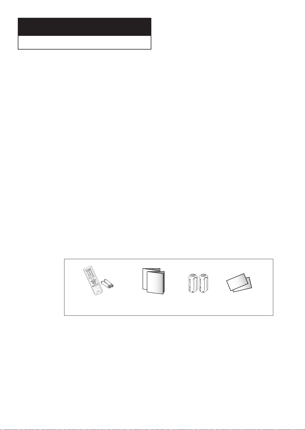
Accessories
Once you have unpacked your TV, check to make sure that you have all the parts shown
here. If any piece is missing or broken, call your dealer.
Remote Control(AA59-00356B)/
AAA Batteries(4301-000121)
Owner’s Instructions
Safety Guide Manual
/
Ferrite core
; 2EA
(3301-001305)
Warranty Card; 2EA/
Registration Card
8
YOUR NEW DIGITAL TV
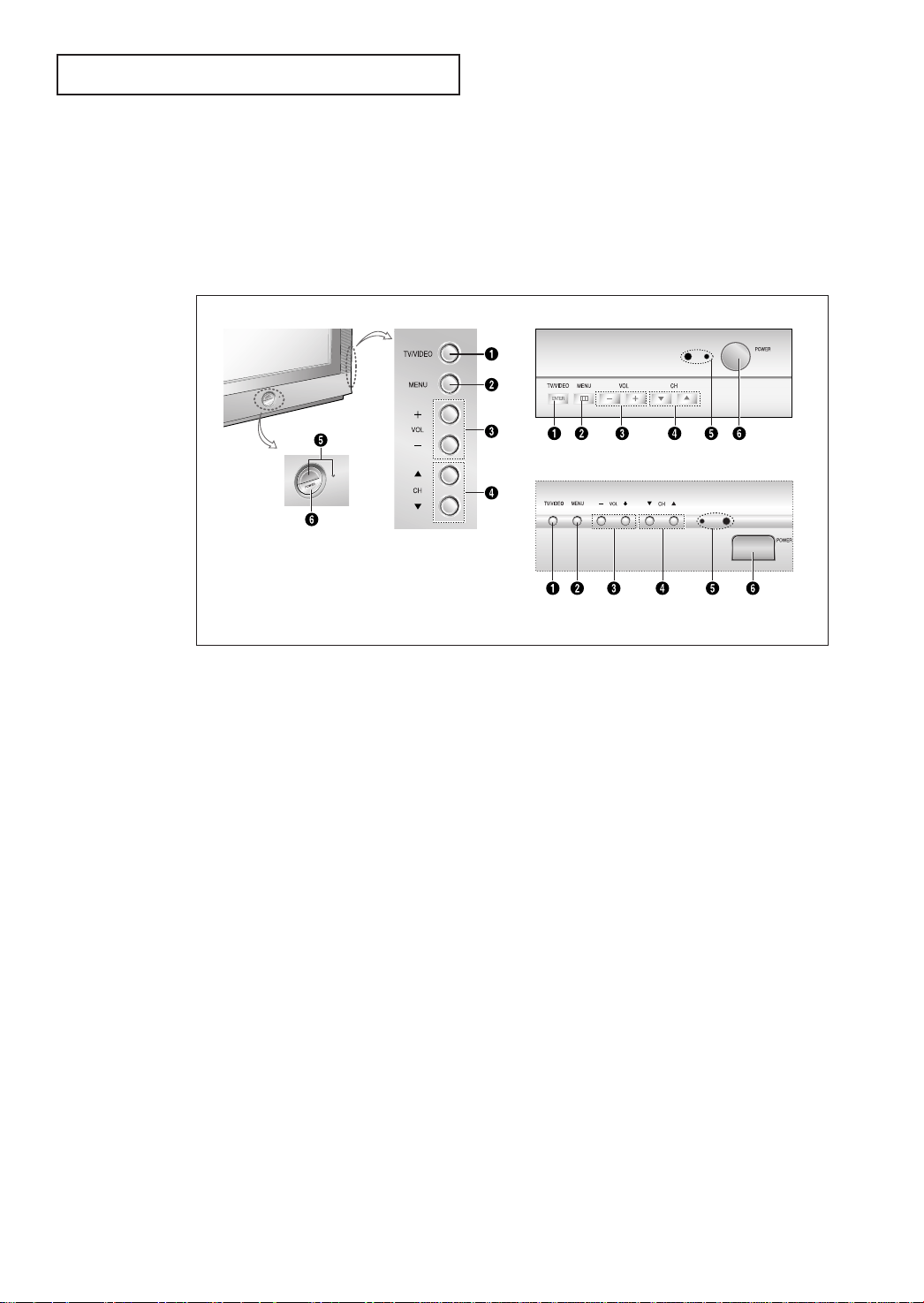
Familiarizing Yourself with Your New TV
Front/Side Panel Buttons
The buttons on the front/side panel control your TV’s basic features, including the on-
screen menu. To use the more advanced features, you must use the remote control.
TX-P3071WH/TX-P3271WH
TX-P2675WH/TX-P3075WH/
TX-P2775WH/TX-P3275WH
TX-P2670WH
Œ
TV/VIDEO & ENTER
Press to change bet ween viewing TV programs
and signals from ot her components.
While using the on-screen menus, press ENTER to
activate(or change) a par ticular i tem.
´
MENU
Press to see an on-screen menu of your TV's features.
ˇ
VOL – , +
Press to increase or decrease the volume.
Also used to select items on the on-screen menu.
¨
CH▼ and CH▲
Press to change channels.Also, press to highlight
various items on the on-screen menu.
ˆ
Remote Control Sensor &
STANDBY indicator
Aim the remote control towards this spot on the TV.
Lights up when you turn the power off.
Ø
POWER
Press to turn the TV on and off.
Note
The Touch-Sensitive buttons do not work.
• Did you use a light touch when pressing the buttons?
• Is the Power Plug correctly connected to the outlet?
• Did you use your finger to touch the button(using a pen or pencil may not work)?
9
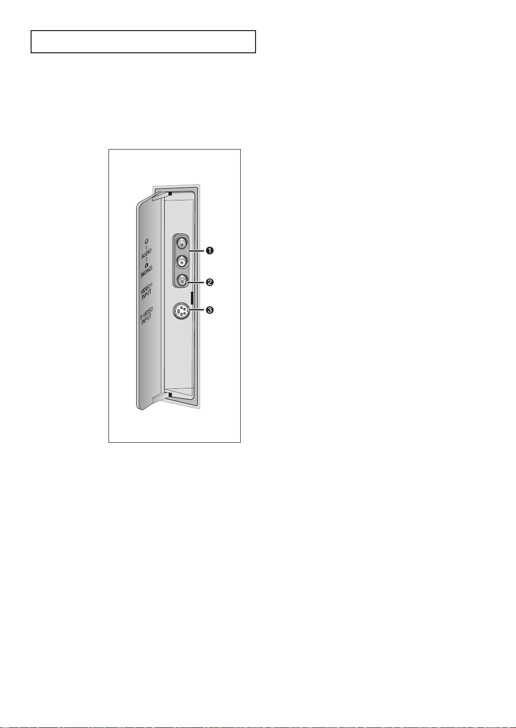
YOUR NEW DIGITAL TV
Side Panel Jacks
You can use the side panel jacks to connect an A/V component that is used only
occasionally, such as a camcorder or video game. (For information on connecting
equipment, see page 23.)
Œ
AUDIO INPUT jacks
Use to connect the audio signals from a camcorder or a video
game.
´
VIDEO1 INPUT jack
Use to connect a video signal from a camcorder or a video
game.
ˇ
S-VIDEO INPUT jack
Use to connect an S-Video signal from a camcorder or a video
game.
Note: In S-Video mode, Audio Output depends what kind of
audio input source is connected to the side audio input jacks
(AV1).
10
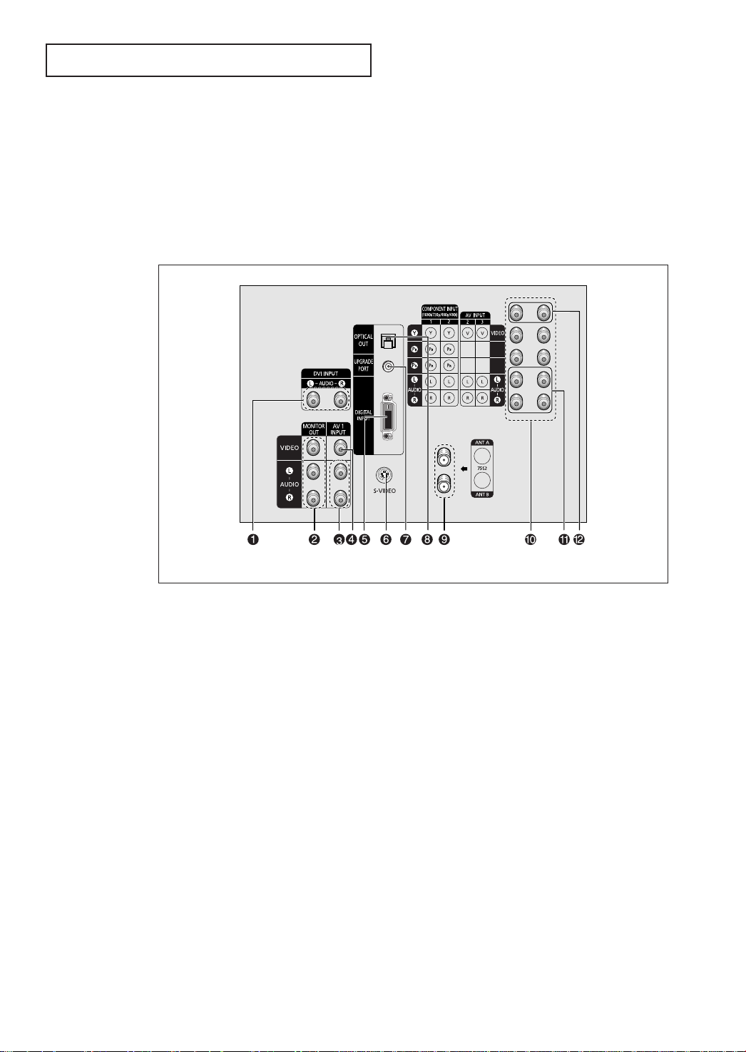
YOUR NEW DIGITAL TV
Rear Panel Jacks
Use the rear panel jacks to connect an A/V component that will be connected continuously, such as a VCR or a DVD player.
Your TV has several input jacks, so you can connect different A/V components simultaneously (i.e., a VCR and a DVD, 2 VCRs, etc.).
For more information on connecting equipment, see page 14~24.
Œ
DVI (Digital Visual Interface)
AUDIO INPUT jacks
Receives the digital audio signals from AV devices.
´
AUDIO-VIDEO MONITOR
OUTPUT jacks
Connect to the audio/video input jacks of a recording VCR.
ˇÔ
AUDIO INPUT1, 2, 3 jacks
Connect to the audio output jacks of VCRs,
DVD players and similar devices.
¨
VIDEO INPUT1, 2, 3 jacks
Connect to the video output jacks of VCRs,
DVD players and similar devices (Three sets
are available: Video1, Video2 and Video3).
ˆ
DIGITAL VIDEO INPUT
(Digital Visual Interface)
jack
Receives the digital signals from a Set-top Box.
Ø
S-VIDEO INPUT jack
Connect to S-VIDEO output jacks of an S-VHS VCR
or DVD player.
Note: In S-Video mode, Audio Output depends
what kind of audio input source is connected to
the side audio input jacks (AV1).
∏
UPGRADE PORT
For service only.
”
OPTICAL OUTPUT jack
Connect to a Digital Audio component.
’
ANTENNA terminals
Two independent cables or antennas can be connected to these terminals. Use ANT A and ANT B
terminals to receive a signal from VHF/UHF antennas or your cable system.
˝
COMPONENT1, 2
(480i, 480p, 720p, 1080i)
AUDIO/VIDEO INPUT jacks
Connect to the Audio & Video outputs of DVD or
DTV Set-Top-Box.
11
YOUR NEW DIGITAL TV
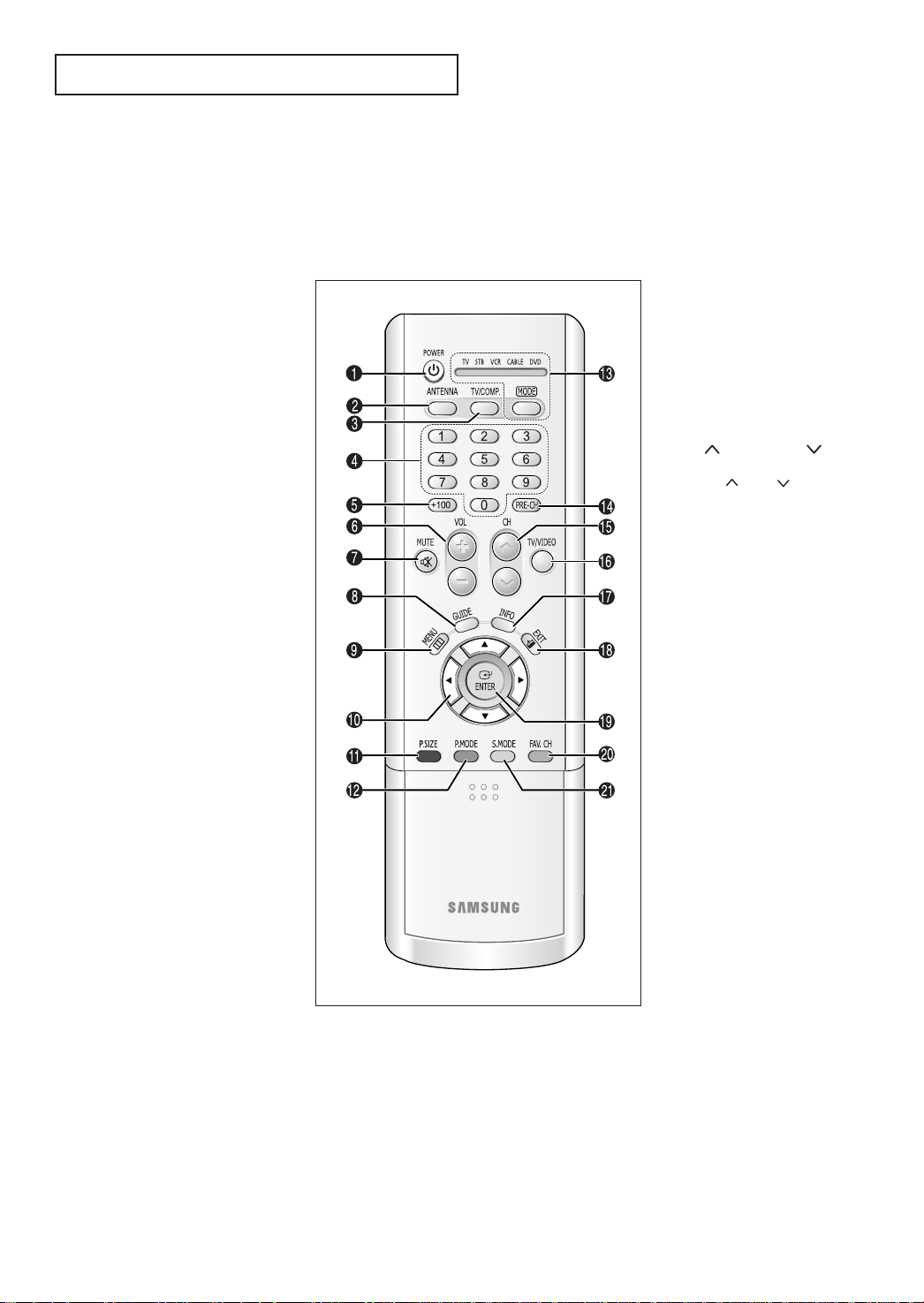
Remote Control
You can use the remote control up to about 23 feet from the TV. When using the remote,
always point it directly at the TV.
You can also use your remote control to operate your Set-Top Box, VCR, Cable Box and
DVD. See page 75 for details.
Œ
POWER
Turns the TV on and off.
´
ANTENNA
Press to select ANT A or
ANT B.
ˇ
TV/COMP.
Press to switch the TV,
COMPONENT1, 2 or DVI mode.
¨
Number buttons
Press to select channels directly on
the TV.
ˆ
+100
Press to select channels over 100.
For example, to select channel 121,
press “+100”, then press “2” and “1”.
Ø
VOL +, VOL -
Press to increase or decrease the
volume.
∏
MUTE
Press to temporarily cut off the
sound.
”
GUIDE
Press to display the on-screen
Electronic Program Guide (EPG).
’
MENU
Displays the main on-screen menu.
˝
Up/Down
Left/Right buttons
Press to select highlight up, down,
left , or right .
Ô
P.SIZE
Press to change the screen size.
P.MODE
Adjust the TV picture by selecting
one of the preset factory settings
(or select your personal,
customized picture set tings).
Ò
MODE
Selects a target device to be controlled by the Samsung remote control(i.e., TV, STB, VCR, Cable box or
DVD ).
Ú
PRE-CH
Tunes to the previous channel.
Æ
CH and CH
(Channel Up/Down)
Press CH or CH to change
channels.
ı
TV/VIDEO
Press to display all of the available
video sources (i.e., Video1,Video2,
Video3, S-Video).
˜
INFO
Press to display information about
the current box settings and
program.
¯
EXIT
Press to exi t the menu.
˘
ENTER
While using the on-screen menus,
press ENTER to activate (or change)
a particular item.
¿
FAV. CH (Favorite
Channel)
Press to switch between your
favorite channels.
¸
S.MODE
Adjust the TV sound by selecting
one of the preset factory settings
(or select your personal,
customized sound set tings).
12
YOUR NEW DIGITAL TV
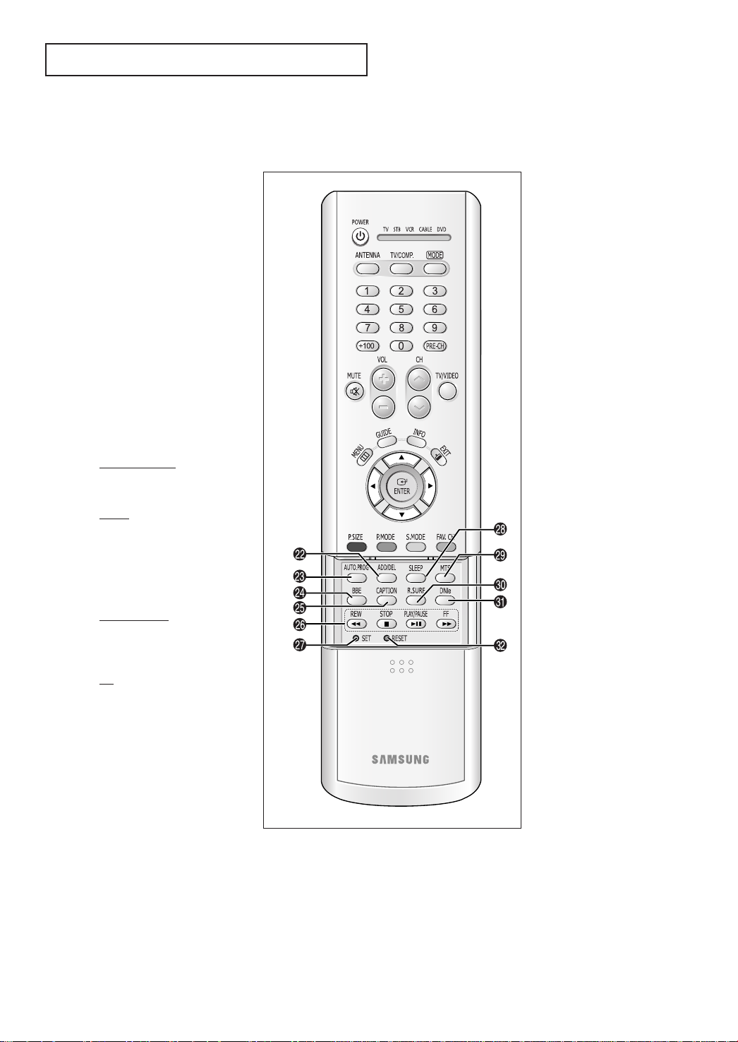
Remote Control (continued)
˛
ADD/DEL
Press to add or erase channels in
the TV’s memory.
◊
AUTO.PROG
Press to display the Memorized
Channels menu.
±
BBE
BBE is a built-in ef fect that adds
clarit y, punch and dynamics to the
sound.
≠
CAPTION
Cont rols t he caption decoder.
–
VCR controls
Controls VCR tape functions:
Rewind, Play, Fast For ward, Stop,
Paus e.
REW (Rewind)
Press to rewind a tape in your
VCR.
STOP
Press this button to stop a tape
during play, record, rewind or fast
forward. If the button is pressed
during Full-Automatic
play, the function will be
cancelled.
÷
SLEEP
Press to select a preset time interval for automatic shutoff.
®
MTS (Multi-channel
Television Sound)
Press to choose stereo, mono or
Secondary Audio Program (SAP
broadcast).
∑
R.SURF
Press the R.SURF button to automatically return to a preferred channel after a user-preset t ime delay.
µ
DNIe
Not available.
¥
RESET
If your remote control is not
functioning properly, take out the
batteries and press the reset
button for about 2~3 seconds.
Re-insert the batteries and try using
the remote control again.
PLAY/P
AUSE
Press the Play/Pause but ton to
play back prerecorded tapes or
pause the tape.
FF
Press to fast forward the tape in
your VCR.
—
SET
Used during set up of this
Samsung remote control, so that it
will work compatibly with other
devices (VCR, cable box, DVD.)
13
2
Chapter Two
INSTALLATION
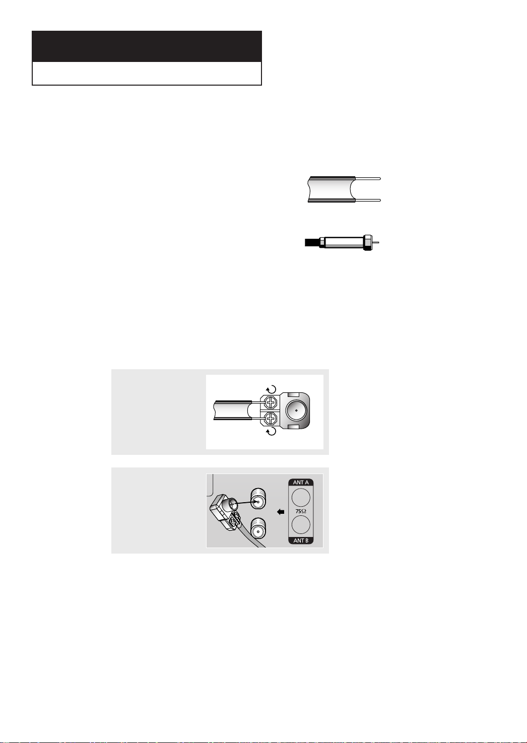
Connecting VHF and UHF Antennas
If your antenna has a set of leads that
look like this, see “Antennas with
300-ohm Flat Twin Leads,” below.
If your antenna has one lead that looks
like this, see “Antennas with 75-ohm
Round Leads,” on page 15.
If you have two antennas, see “Separate
VHF and UHF Antennas,” on page 15.
Antennas with 300-ohm Flat Twin Leads
If you are using an off-air antenna (such as a roof antenna or “rabbit ears”) that has 300ohm twin flat leads, follow the directions below.
1
Place the wires from the
twin leads under the
screws on the 300-75 ohm
adaptor (not supplied).
Use a screwdriver to
tighten the screws.
2
Plug the adaptor into the
ANT A or ANT B terminal
on the rear panel.
14
INSTALLATION
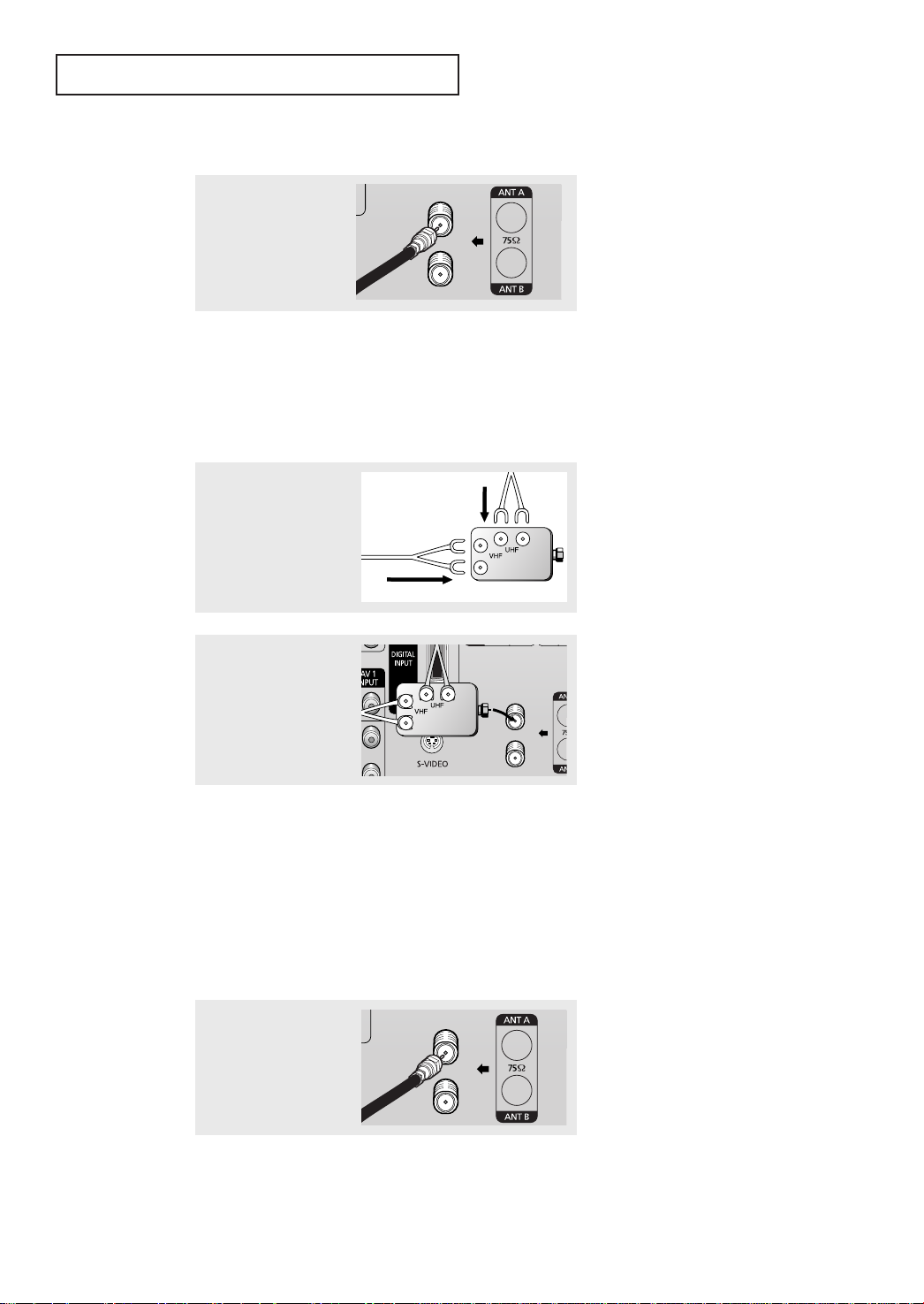
Antennas with 75-ohm Round Leads
Plug the antenna lead into
the ANT A or ANT B terminal on the rear panel.
Separate VHF and UHF Antennas
If you have two separate antennas for your TV (one VHF and one UHF), you must combine
the two antenna signals before connecting the antennas to the TV. This procedure requires
an optional combiner-adaptor (available at most electronics shops).
1
Connect both antenna
leads to the combiner.
2
Plug the combiner into the
ANT A or ANT B terminal on t he rear panel.
Connecting Cable TV
You can connect different cable systems to your TV, including cable without a cable box,
and cable with a cable box that descrambles some or all channels.
Cable without a Cable Box
If you want to connect cable, and you do not need to use a cable box:
Plug the incoming cable
into the ANT A or ANT B
antenna terminal on the
rear of the TV.
15
INSTALLATION
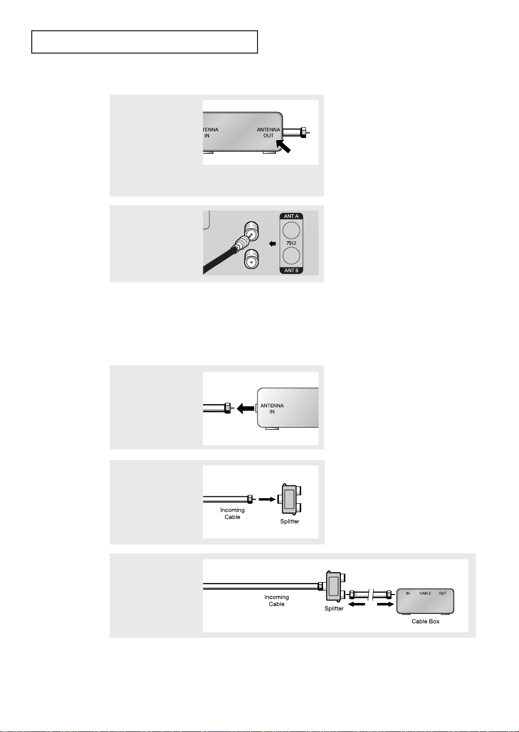
Cable with a Cable box that Descrambles All Channels
1
Find the cable that is
connected to the ANTENNA OUT terminal on your
cable box. This terminal
might be labeled “ANT
OUT”, “VHF OUT”, or simply,“OUT”.
2
Connect the other end of
this cable to the ANT Aor
ANT B terminal on t he
rear of the TV.
Connecting to a Cable Box that Descrambles Some Channels
If your cable box descrambles only some channels (such as premium channels), follow the
instructions below. You will need a two-way splitter, an RF (A/B) switch, and four lengths of
coaxial cable. (These items are available at most electronics stores.)
▼
1
Find and disconnect the
cable t hat is connected to
the ANTENNA IN terminal on your cable box.
This terminal might be labeled
“ANT IN,” “VHF IN,” or simply,
“IN.”
16
2
Connect this cable to a
two-way split ter.
3
Connect a coaxial cable
between an OUTPUT
terminal on the splitter and
the IN terminal on the
cable box.
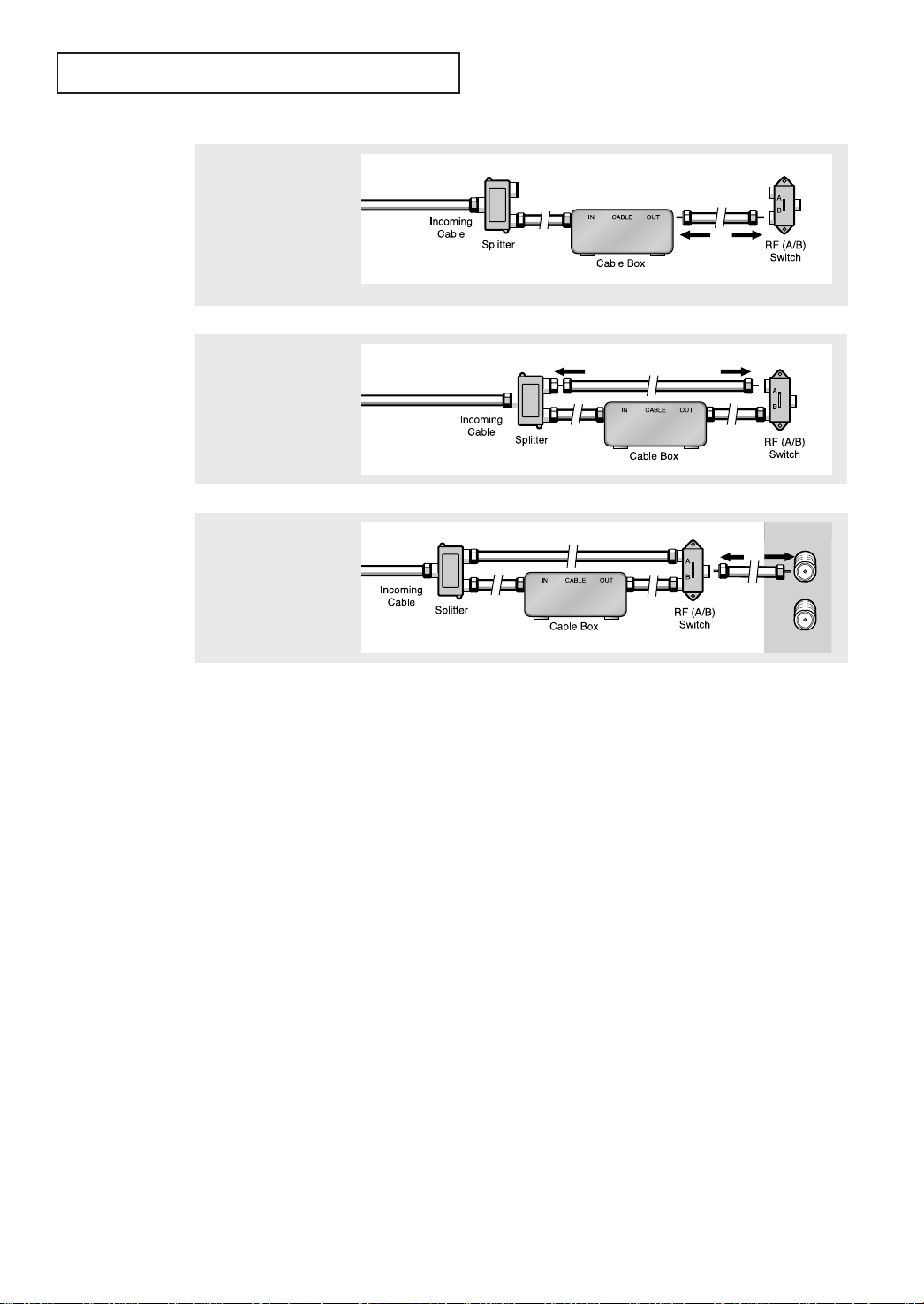
INSTALLATION
4
Connect a coaxial cable
between the ANTENNA
OUT terminal on the cable
box and the B–IN terminal
on the A/B switch.
5
Connect another cable
between the other OUT
terminal on the splitter and
the A–IN terminal on the
RF (A/B) switch.
6
Connect the last coaxial
cable between the OUT
terminal on the RF (A/B)
switch and the ANT A or
ANT B terminal on the rear
of the TV.
After you’ve made this connection, set the A/B switch to the “A” position for normal viewing. Set the A/B switch to the “B” position to view scrambled channels. (When you set the
A/B switch to “B,” you will need to tune your TV to the cable box’s output channel, which is
usually channel 3 or 4.)
17
INSTALLATION
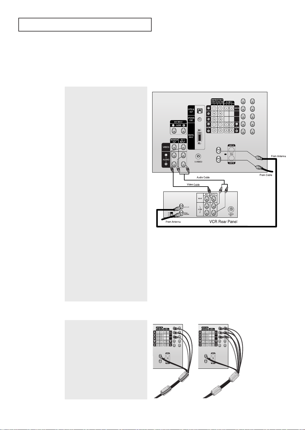
Connecting a VCR
These instructions assume that you have already connected your TV to an antenna or a
cable TV system (according to the instructions on pages 14~17). Skip step 1 if you have not
yet connected to an antenna or a cable system.
TV Rear Panel
1
Unplug the cable or antenna from the
back of the TV.
2
Connect the cable or antenna to the
ANTENNA IN terminal on the back of the
VCR.
3
Connect a coaxial cable between the
ANTENNA OUT terminal on the VCR and
the antenna terminal on the TV.
4
Connect a set of audio cables between
the AUDIO OUT jacks on the VCR and the
AUDIO jacks (AV1~AV3) on the TV.
If you have a “mono” (non-stereo) VCR,
use a Y-connector (not supplied) to hook
up to the left and right audio input jacks
of the TV. If your VCR is stereo, you must
connect two cables.
5
Connect a video cable between the
VIDEO OUT jack on the VCR and the
VIDEO jack (AV1~AV3) on the TV.
Follow the instructions in “Viewing an
Ex ternal Signal Source” to view your VCR
tape.
Ferrite Core
The ferrite core is used to attenuate undesired signals. When connecting cables, attach
the ferrite core to the cable near the connector.
TV Rear Panel
18
INSTALLATION
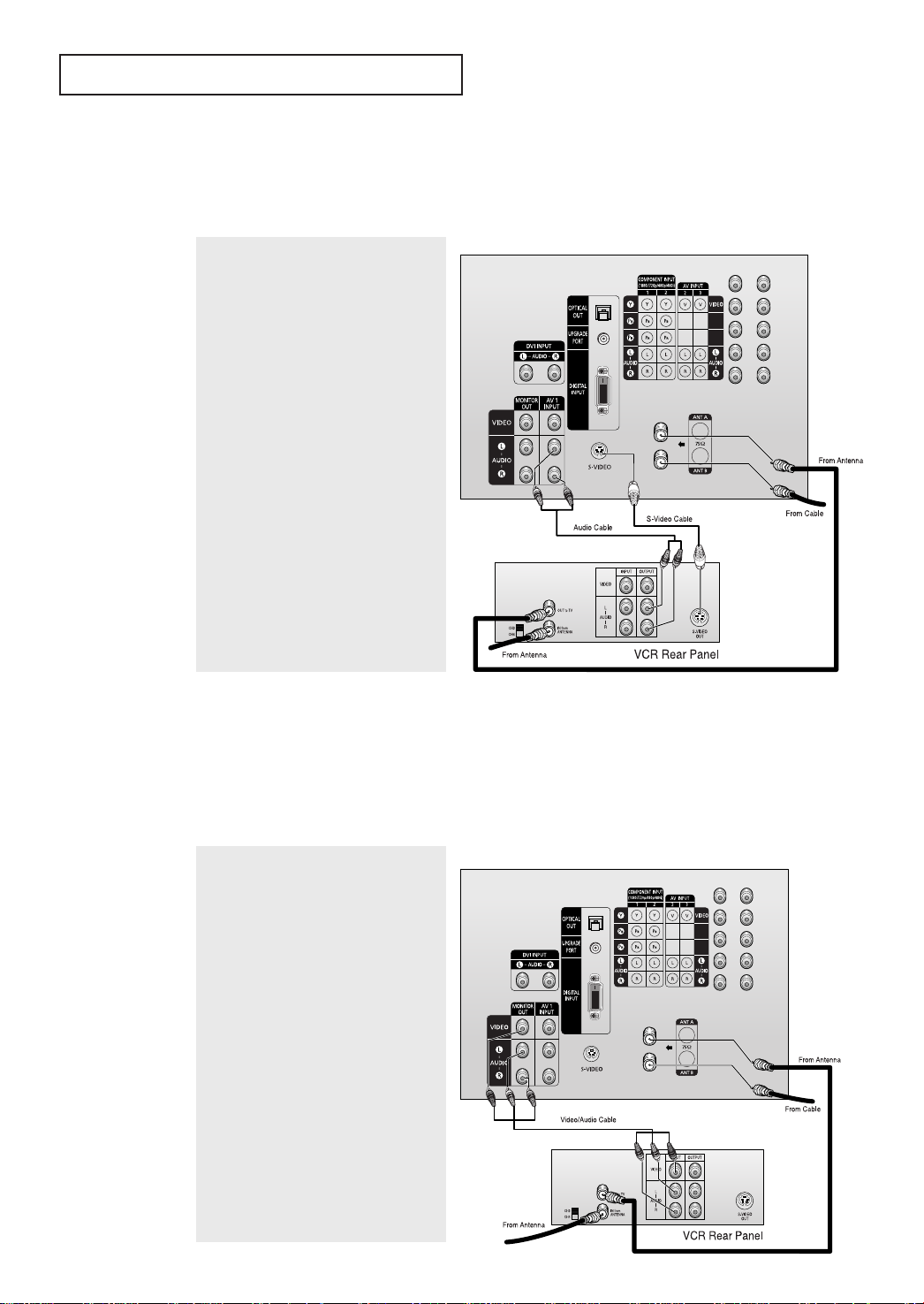
Connecting an S-VHS VCR
Your TV can be connected to an S-Video signal from an S-VHS VCR. (This connection delivers
a better picture as compared to a standard VHS VCR.)
1
TV Rear Panel
To begin, follow steps 1–3 in the previous
section to connect the antenna or cable
to your VCR and your TV.
2
Connect a set of audio cables between the
AUDIO OUT jacks on the VCR and the
AUDIO IN 1 jacks on the TV.
3
Connect an S-video cable between the
S-VIDEO OUT jack on the VCR and the
S-VIDEO jack on the TV.
An S-video cable is usually included with an S-VHS VCR. (If not, check your local
electronics store.)
Connecting a Second VCR to Record from the TV
Your TV can send out signals of its picture and sound to be recorded by a second VCR.
To do this, connect your second VCR as follows:
1
Connect a set of audio cables between
the AUDIO OUT jacks on the TV and the
AUDIO IN jacks on the VCR. (The VCR
input jacks might be either on the front or
on back of the VCR.)
TV Rear Panel
2
Connect a video cable between the
VIDEO OUT jack on the TV and the VIDEO
IN jack on the VCR.
Refer to your VCR’s instructions for more
information about how to record using
this kind of connection.
19
INSTALLATION
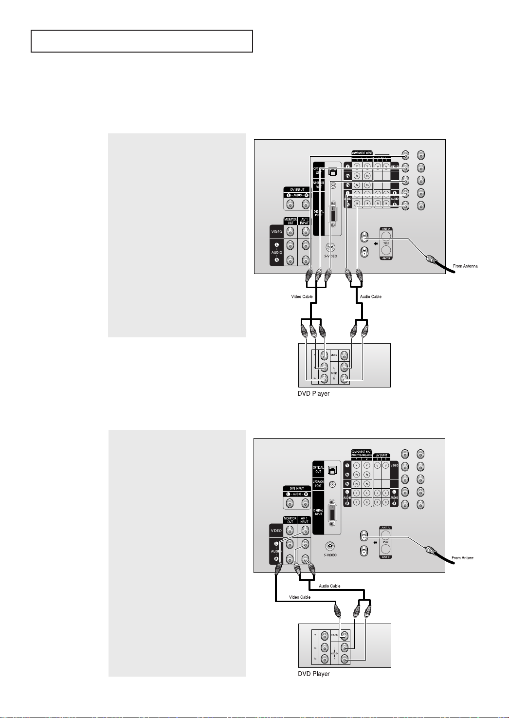
Connecting a DVD Player
Connecting to Y, PB, PR
The rear panel jacks on your TV make it easy to connect a DVD player to your TV.
TV Rear Panel
1
Connect a set of audio cables between
the COMPONENT1 INPUT (L, R) or COMPONENT 2 INPUT (L, R) jacks on the TV
and the AUDIO OUTjacks on the DVD
player.
2
Connect a video cable between the
COMPONENT 1INPUT (Y, PB,PR) or COM-
PONENT 2 INPUT (Y, PB,PR) jacks on the
TV and the DVD OUT (Y, PB,PR) jacks on
the DVD player.
Note: For an explanation of
Component video, see your DVD
player's owner's manual.
20
Connecting to Regular Audio and Video Jacks
TV Rear Panel
1
Connect a set of audio cables between
the AUDIO IN jacks(AV1~AV3) on the TV
and the AUDIO OUTjacks on the DVD
player.
2
Connect video cables bet ween the VIDEO
OUT jack on the DVD player and the
VIDEO IN jack(AV1~AV3) on the TV.

INSTALLATION
Connecting a Digital TV Set-Top Box (480p/720p/1080i)
Connecting to Y, PB, PR
Connect the Y, PB, and PR video outputs of the set-top box to their corresponding inputs on the
TV. Next, connect the Left and Right audio from the set-top box to the corresponding L and R
terminals on the TV. (The connections for a typical set-top box are shown below.)
TV Rear Panel
1
Connect a coaxial cable to the ANTENNA
IN terminal on the Set-Top Box and the
antenna terminal on the TV.
2
Connect a set of audio cables between
the COMPONENT1 INPUT (L, R) or COMPONENT 2 INPUT (L, R) jacks on the TV
and the AUDIO OUTjacks on the Set Top
Box.
3
Connect a video cable between the
COMPONENT 1 INPU T (Y, PB,PR) or COM-
PONENT 2 INPUT (Y, PB,PR) jacks on the
TV and the VIDEO OUT(Y, PB,PR) jacks on
the Set Top Box.
Note: For detailed information, refer to
the Set Top Box instruction manual.
21
INSTALLATION
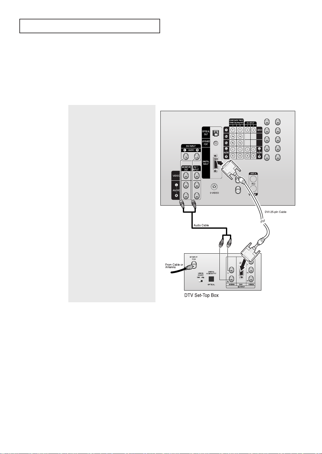
Connecting to DVI (Digital Visual Interface)
By inputting a high-bandwidth Digital Content Protection high-definition picture source to the
DIGITAL INPUT jack on the TV, high-definition pictures can be displayed on the screen in
their digital forms. (This DIGITAL INPUT jack is for use in the future when High-bandwidth
Digital Content Protection DTV decoders, DVD players and D-VHS are put on the market.)
1
Connect a coaxial cable to the ANTENNA
IN terminal on the Set-Top Box and the
antenna terminal on the TV.
2
Connect a set of audio cables between
the DVI INPUT(AUDIO L, R) jacks on the
TV and the AUDIO OUT jacks on the Set
Top B ox .
3
Connect a DVI cable between the DIGITAL INPUT jack on the TV and the DVI
OUT jack on the Set Top Box.
TV Rear Panel
22
Notes
• The DIGITAL INPUT jack can only be used with 1080i, 720p and 480p picture signals.
Set the DTV decoder DIGITAL OUTPUT jack output setting to 1080i, 720p or 480p.
For detailed information, refer to the Set Top Box instruction manual.
• The DIGITAL INPUT jack is not compatible with the picture signal of a personal computer.
• Use a DVI 25-pin cable (commercially available) in order to digitally connect the TV with a
DTV Set-top box.
INSTALLATION
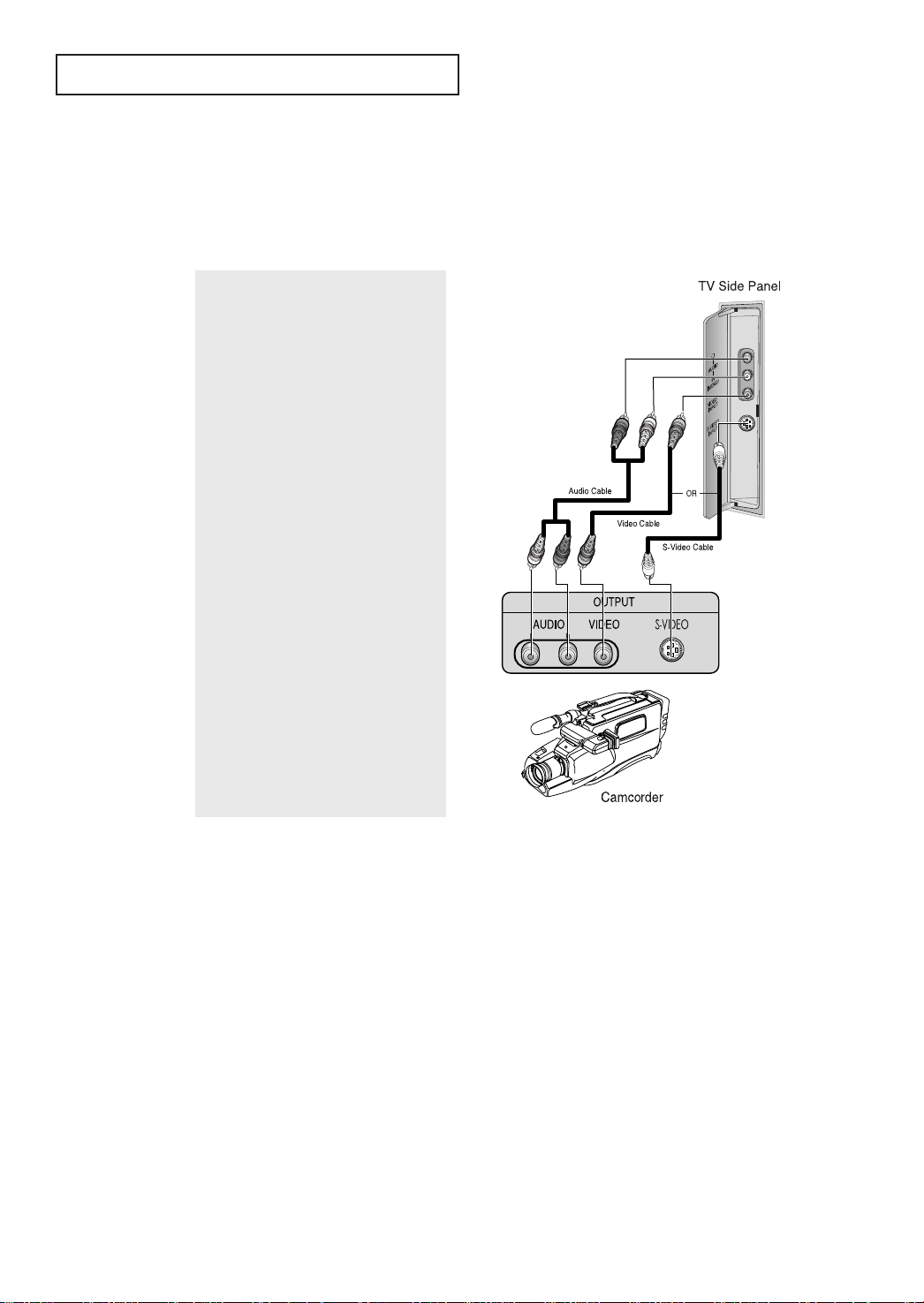
Connecting a Camcorder
The side panel jacks on your TV make it easy to connect a camcorder to your TV. They allow
you to view the camcorder tapes without using a VCR. (Also see “Viewing an External Signal
Source” on page 44).
1
Locate the A/V output jacks on the camcorder. They are usually found on the side
or back of the camcorder.
2
Connect an audio cable between the
AUDIO OUT jack on the camcorder and
the AUDIO terminals on the TV.
3
Connect a video cable between the
VIDEO OUT jack on the camcorder and
the VIDEO(or S-VIDEO) terminal on the
TV.
The audio-video cables shown here are
usually included with a Camcorder.
(If not, check your local elect ronics
store.) If your camcorder is stereo, you
need to connect a set of two cables.
23
INSTALLATION
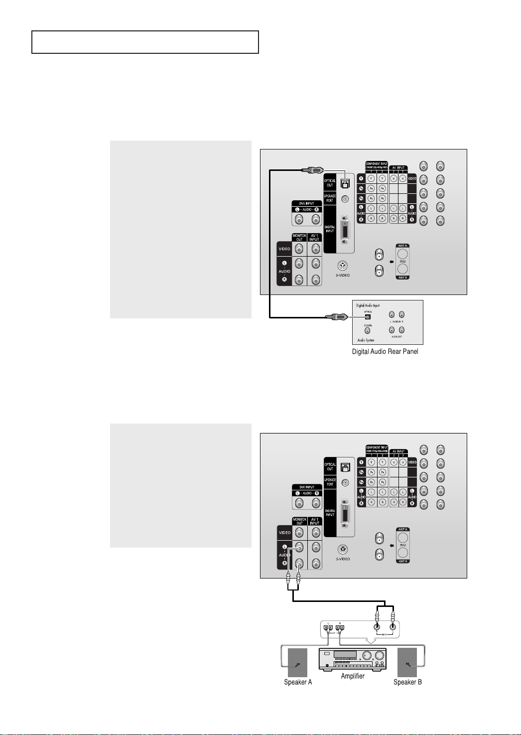
Connecting to a Digital Audio System
There are many types of audio systems on the market today.
A simplified illustration of an audio system is shown below. For more information, see your
audio system owner’s manual.
TV Rear Panel
1
If your system has an optical digital audio
input, connect it to the OPTICAL OUT jack
on the TV.
Be certain to remove the black cover
from the optical output before inserting
the cable.
2
If your system has a optical digital audio
input , SAMSUNG recommends you use
the optical digital output on the TV.
Connecting to an External Amplifier (Variable Audio Output)
TV Rear Panel
The “AUDIO OUT” terminals cannot be
used for external speakers. You must
hook them up to an amplifier.
When an audio amplifier is connected to
the “AUDIO OUT” terminals:
Decrease the gain (volume) of the audio
amplifier, and adjust the volume level
with the volume control on the TV.
24
 Loading...