

Samsung SV-R960PRT User Manual

SVR-24PRT
SVR-960PRT
Time Lapse Recorder
Installation and
Operating Instructions
IMPORTANT SAFEGUARDS
1. Read Instructions - All the safety and operating instructions should
be read before the unit is operated.
2. Retain Instructions - The safely and operating instructions should be
retained for future reference.
3. Head Warnings - All warnings on the unit and in the operating
instructions should be adhered to.
4. Follow Instructions - All operating and use instructions should be
followed.
5.
Cleaning - Unplug the unit from the outlet before cleaning. Do not use
liquid cleaners or aerosol cleaners. Use a damp cloth for cleaning.
6. Attachments - Do not use attachments not recommended by the unit
manufacturer as they may cause hazards.
7. Water and Moisture - Do not use this unit near water-for example,
near a bath tub, wash bowl, kitchen sink, or laundry tub, in a wet
basement, near a swimming pool, in an unprotected outdoor
installation, or any area which is classified as a wet location.
8. Accessories - Do not place this unit on an unstable stand, tripod,
bracket, or mount. The unit may fall, causing serious injury to a
person and serious damage to the unit. Use only with a stand, tripod,
bracket, or mount recommended by the manufacturer, or sold with
the unit. Any mounting of the unit should follow the
manufacturer's instructions, and should use a
mounting accessory recommended by the
manufacturer. An appliance and cart
combination should be moved with care. Quick
stops, excessive force, and uneven surfaces may
cause the appliance and cart combination to
overturn.
9. Ventilation - Operatings in the enclosure, if any, are provided for
ventilation and to ensure reliable operation of the unit and to protect
it from overheating. These openings must not be blocked or covered.
This unit should not be placed in a built-in installation unless proper
ventilation is provided or the manufacturer's instructions have been
adhered to.
10. Power Sources - This unit should be operated only from the type of
power source indicated on the marking label. If you are not sure of
the type of the power supply you plan to use, consult your appliance
dealer or local power company. For units intended to operate from
battery or other sources, refer to the operating instructions.
11. Grounding or Polarization - This unit may be equipped with a
polarized alternating-current line plug (a plug having one blade
wider than the other). This plug will fit into the power outlet only one
way. This is a safety feature. If you are unable to insert the plug fully
into the outlet, try reversing the plug. If the plug should still fail to fit,
contact your electrician to replace your obsolete outlet. Do not
defeat the safety purpose of the polarized plug. Alternately, this unit
may be equipped with a 3-wire grounding-type plug, a plug having a
third (grounding) pin. This plug will only fit into a grounding-type
power outlet. This is a safety feature. If you are unable to insert the
plug into the outlet, contact your electrician to replace your obsolete
outlet. Do not defeat the safety purpose of the grounding-type plug.
12. Power - Cord Protection-Power-supply cords should be routed so
that they are not likely to be walked on or pinched by items placed
upon or against them, paying particular attention to cords and plugs,
convenience receptacles, and the point where they exit from the
appliance.
13. Power Lines - An outdoor system should not be located in the
vicinity of overhead power lines or other electric light or power
circuits, or where it can fall into such power lines or circuits. When
installing an outdoor system, extreme care should be taken to keep
from touching such power lines or circuits as contact with them
might be fatal. U.S.A. models only-refer to the National Electrical
Code Article 820 regarding installation of CATV systems.
14. Overloading - Do not overload outlets and extension cords as this
can result in a risk of fire or electric shock.
15. Object and Liquid Entry - Never push objects of any kind into this
unit through openings as they may touch dangerous voltage points
or short-out parts that could result in a fire or electric shock. Never
1
spill liquid of any kind on the unit.
16. Servicing - Do not attempt to service this unit yourself as opening or
removing covers may expose you to dangerous voltage or other
hazards. Refer all servicing to qualified service personnel.
17. Damage Requiring Service - Unplug the unit from the outlet and
refer servicing to qualified service personnel under the following
conditions:
a. When the power - supply cord. or plug is damaged.
b. If liquid has been spilled, or objects have fallen into the unit.
c. If the unit has been exposed to rain or water.
d. If the unit does not operate normally by following the operating
instructions. Adjust only those controls that are covered by the
operating instructions, as an improper adjustment of other
controls may result in damage and will often required extensive
work by a qualified technician to restore the unit to its normal
operation.
e. If the unit has been dropped or the cabinet has been damaged.
f. When the unit exhibits a distinct change in performance this
indicates a need for service.
18. Replacement Parts - When replacement parts are required, be sure
the service technician has used replacement parts specified by the
manufacturer or have the same characteristics as the original part.
Unauthorized substitutions may result in fire, electric shock or other
hazards.
19. Safety Check - Upon completion of any service or repairs to this
unit, ask the service technician to perform safety checks to
determine that the unit is in proper operating condition.
20. Coax Grounding - If an outside cable system is connected to the
unit, be sure the cable system is grounded. U.S.A models onlySection 810 of the National Electrical Code, ANSI/NFPANo. 701981, provides information with respect to proper grounding of the
mount and supporting structure, grounding of the coax to a
discharge unit, size of grounding conductors, location of discharge
unit, connection to grounding electrodes, and requirements for the
grounding electrode.
21. Lightning - For added protection of this unit during a lightning storm
or when it is left unattended and unused for a long period of time,
unplug power cord form the wall.
FCC & ICES INFORMATION
(U.S.A and Canadian Models Only)
WARNING - This equipment has been tested and found to comply with
the limits for a Class B digital device, pursuant to Part 15 of the FCC
Rules and ICES-003 of Industry Canada. These limits are designed to
provide reasonable protection against harmful interference when the
equipment is operated in a residential installation. This equipment
generates, uses and can radiate radio frequency energy and, if not
installed and used in accordance with the instruction, may cause
harmful interference to radio communications. However, there is no
guarantee that interference will not occur in a particular installation. If
this equipment does cause harmful interference to radio or television
reception, which can be determined by turning the equipment off and
on, the user is encouraged to try to correct the interference by one or
more of the following measures:
– Reorient or relocate the receiving antenna.
– Increase the separation between the equipment and receiver.
– Connect the equipment into an outlet on a circuit different from that to
which the receiver is connected.
– Consult the dealer or an experienced radio/TV technician for help.
Intentional or unintentional changes or modifications not expressly
approved by the party responsible for compliance shall not be made.
Any such changes or modifications could void the user's authority to
operate the equipment.
The user may find the following booklet prepared by the Federal
Communications Commission helpful: "How to Identify and Resolve
Radio-TV Interference Problems". This booklet is available from the
U.S. Government Printing Office, Washington, DC 20402, Stock
No.004-000-00345-4.
Safety Precautions
CAUTION
RISK OF ELECTRICK SHOCK
DO NOT OPEN!
CAUTION: TO REDUCE THE RISK OF
ELECTRICAL SHOCK, DO NOT OPEN COVERS.
NO USER SERVICEABLE PARTS INSIDE.
REFER SERVICING TO QUALIFIED SERVICE
PERSONNEL.
This label may appear on the bottom of the unit due to
space limitations.
The lightning flash with an arrowhead
symbol, within an equilateral triangle, is
intended to alert the user to the
presence of uninsulated "dangerous
voltage" within the unit's enclosure that
may be of sufficient magnitude to
constitute a risk of electric shock to
persons.
The exclamation point within an
equilateral triangle is intended to alert
the user to presence of important
operating and maintenance (servicing)
instructions in the literature
accompanying the appliance.
Warning
To prevent fire or shock hazard, do not expose
units not specifically designed for outdoor use to
rain or moisture.
Attention: Installation should be
performed by qualified service
personnel only in accordance with the
National Electrical Code or applicable
local codes.
Power Disconnect. Units with or
without ON-OFF switches have power
supplied to the unit whenever the power
cord is inserted into the power source;
however, the unit is operational only
when the ON-OFF switch is in the On
position. The power cord is the main
power disconnect for all units.
Securite
ATTENTION
RISQUE DE CHOC ELECTRIQUE,
NE PAS OUVRIR.
Danger: Pour éviter tout risque d'électrocution, ne
pas ouvrir le boîtier. Il n'y a pas de pièces
remplaçables à l'intérieur. Pour toute révision,
s'adresser à un technicien spécialisé.
Cet étiquette peut apparaître en dessous de l'appareil
dû aux limitations d'espace.
L'éclair fléché dans un triangle
équilatéral avertit l'utilisateur de la
présence d'une haute tension non
isolée à l'intérieur de l'appareil. Elle peut
être d'une magnitude suffisante pour
constituer un risque d'électrocution.
Le point d'exclamation à l'intérieur d'un
triangle équilatéral avertit l'utilisateur de
la présence d'instructions importantes
d'utilisation et de maintenance dans la
documentation accompagnant
l'appareil.
Attention
Pour éviter un incendie ou une électrocution, ne pas
exposer les appareils qui ne sont pas conçus spécifiquement pour usage extérieur à la pluie ou à l'humidité.
Attention: L'installation doit être
effectuée uniquement par du personnel
de service qualifié conformément à la
réglementation du Code Electrique
National ou à la réglementation locale.
Disjonction de l'alimentation.
Les appareils avec ou sans commutateure
ON-OFF sont alimentés à chaque fois que
le cordon d'alimentation est branché à la
source d'alimentation; toutefois, les
appareils disposant de commutateurs ONOFF ne fonctionnent que lorsque le
commutateur ON-OFF est sur la position
ON. Le cordon d'alimentation est la
disjonction d'alimentation principale pour
tous les appareils.
2
ATION
ATION
CONFIGUR-
CONFIGUR-

IMPORTANT SAFEGUARDS CONTENTS
Sicherheitsvorkenhrungen
ACHTUNG!
HOCHSPANNUNGSGEFAHR
NICHT ÖFFNEN!
Warnung: Verhindern Sie einen möglichen
Elektroschlag, indem Sie die Abdeckung nicht
entfernen. Wenden Sie sich bei der Wartung an
dafür qualifiziertes Personal.
Dieses Zeichen kann aus Platzgründen auf der
Unterseite des Gerätes angebracht sein.
Dieses Zeichen weist den Benutzer auf
die nicht isolierte Hochspannung
innerhalb der Anlage hin. Es besteht die
Gefahr eines Elektroschlages.
Das Ausrufezeichen in dem
gleichseitigen Dreieck ist dazu da, den
Benutzer auf wich-tige Inbetriebnahmeund Instandhaltungs-vorschriften
hinzuweisen, die dem Gerät in Form
einer Broschüre beigelegt sind.
Warnung
Um das Risiko von Feuer oder Elektroschlag zu
vermeiden, darf weder das Gerät selbst, noch das
Netzgerät Regen oder Feuchtigkeit ausgesetzt werden.
Achtung!: Die Installation sollte nur von
qualifiziertem Kundendienstpersonal
gemäß jeweilig zutreffender
Elektrovorschriften ausgeführt werden.
Netzanschluß. Geräte mit oder ohne
Netzschalter haben Spannung am
Gerät anliegen, sobald der Netzstecker
in die Steckdose gesteckt wird. Das
Gerät ist Jedoch nur betriebsbereit,
wenn der Netzschalter (EIN/AUS) auf
EIN steht. Wenn man das Netzkabel
aus der Stekdose zieht, dann ist die
Sapnnungszuführung zum Gerät
vollkommen unterbrochen.
Note: You may hear the clicking sound when you press key buttons in the front.
It is natural sound caused by “solenoid” which is to enforce the control for the spinning of the capstan
motor. The capstan motor in this VCR is ball bearing type which lasts more than 10,000 hours.
Precauciones De Seguridad
Precaution: Pare Reducir El Riesgo De Choque
Eléctrico, Favor No Abrir La Cubierta. Este Equipo
No consta De Piezas O Partes Que Requieren
Servicio O Mantenimiento. Para Reparaciones
Favor Referirse AUn Técnico Calificado.
Debido a limitaciones de espacio, esta etiqueta puede
aparecer en la parte inferior de la unidad.
Peligro
Para evitar el peligro de incendio ó choque eléctrico, no
exponga a la lluvia ó humedad, equipos que no han sido
diseñados para uso exterior.
3
PRECAUTION
RIESGO DE CHOQUE
ELECTRICO INO ABRIRI
El símbolo representado por un relámpago
con punta de flecha dentro de un triángulo
equilátero, se muestra con el objetivo de
alertar al usuario que existen "voltages
peligrosos" sin aislamiento, dentro de la
cubierta de la unidad. Dichos voltages
pueden ser de tal magnitud que constituyen
un riesgo de choque eléctrico a personas.
El símbolo de exclamación dentro de
un triángulo equilátero, se muestra con
el objetivo de alertar al ususario de que
instrucciones de operación y
mantenimiento importantes acompañan
al equipo.
Atención: La instalación de este equipo
debe ser realizada por personal capacitado,
solo en acuerdo, y en cumplimiento de
normas del "National Electric Code" (Código
Eléctrico Nacional) ó las normas del
Gobierno Nacional Local.
Para Desconectdar la Alimentación:
Unidades no equipadas con interruptores
ON/OFF, son alimentadas cuando el cable
de alimentación, es conectado a la corriente
eléctrica. Las unidades equipadas con
interruptores son alimentadas de igual
forma, pero adicionalmente requieren qur el
interruptor esté posicionado en ON. El cable
de alimentación es el medio principal de
desconexión del equipo.
CONFIGURATION
Important Safeguards 1
Contents 4
Controls and Indicators 5
Connectors 8
Set Up 9
MENU
How to Set Menu 11
Setting Current Time 13
Setting Menu 16
PLAYBACK
Operation 21
Various Playbacks 23
RECORDING
Set before Recording 27
Record Locking 28
Basic Recording 29
Series Recording 31
Alarm Recording 32
FUNCTION
Alarm Functions 33
High Picture 35
Convenient Functions 36
CONNECTION
Method of Connection 37
Series Recording, Alarm Connections 38
MAINTENANCE
Maintenance 39
Troubleshooting 40
Daily Checks 43
Before Requesting Service 44
Specifications 45
UNPACKING
Unpack carefully. This is electronic equipment and
should be handled with care.
If an item appears to have been damaged in
shipment, replace it properly in its carton and
notify the shipper. If any items are missing, notify
your Sales Representative or Customer Service.
The shipping carton is the safest container in
which the unit may be transported.
Save it for possible future use.
SERVICE
WARNING: Electrostatic-sensitive device. Use
proper CMOS/MOSFET handling precautions
to avoid electrostatic discharge.
NOTE: Grounded wrist straps must be worn
and proper ESD safety precautions observed
when handling the electrostatic-sensitive
printed circuit boards.
DESCRIPTION
The SVR-24PRT/SVR-960PRT Video Cassette
Recorder offers time-lapse in 8 and 40-hour (6 and
30 hour) selectable speeds for a variety of CCTV
applications.
INSTALLATION
Install the SVR-24PRT/SVR-960PRT in
environments where the operating temperature is
+5°C to +40°C (+41°F to +104°F) and the relative
Humidity is 0% to 80% relative, noncondensing.
4
ATION
ATION
CONFIGUR-
CONFIGUR-
MENU
PLAYBACK
RECORDING
FUNCTION
TION
CONNEC-
ANCE
MAINTEN-
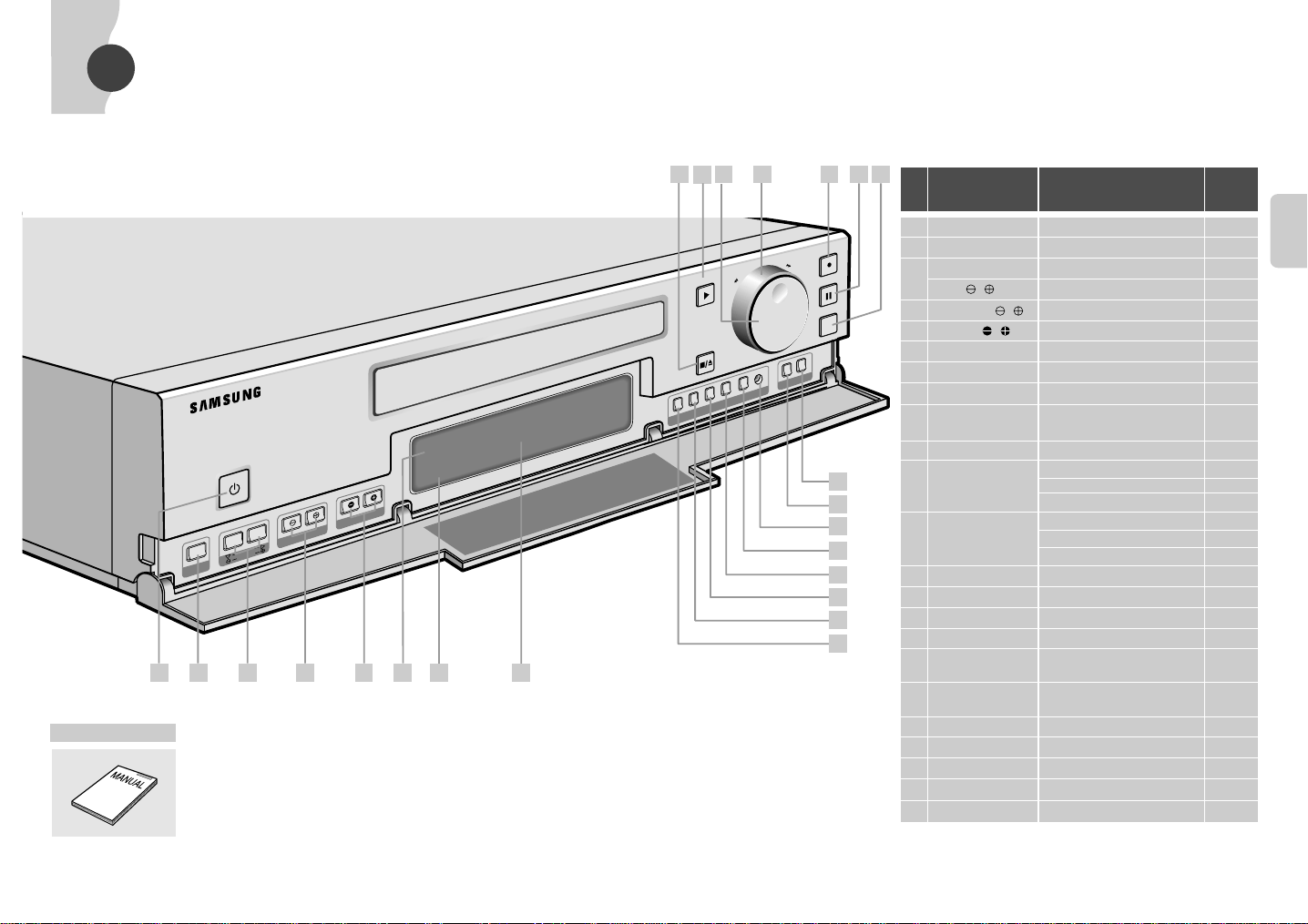
CONTROLS AND INDICATORS
POWER
PLAY
REC
P/STILL
REC CHECK
STOP/EJECT
MENU
V
-L
O
C
K
TRACKING/SET
T
IM
E
M
O
D
E
R
E
C
L
O
C
K
REV
A
U
DIO
O
N
CO
UNT
CNT.M
EM
O
CLEAR
RESET
H
IG
H
P
IC
T
U
R
E
R
E
C
L
O
C
K
1 2 3 4 5 6
9
10
11
12
13
14
15
16
171920
22
18
H
IG
H
P
IC
T
U
R
E
S
H
IF
T
REW
F.F
7 8
23 21
ACCESSORY
INSTRUCTION MANUAL
5
No Name Description
Reference
Page
1 POWER Push for power on/off 21
ATION
2 MENU Push to display menu display 11
3 SHIFT❷,
❿
Push to set menu and clock 11
ATION
CONFIGUR-
CONFIGUR-
V-LOCK , Push to adjust jitter of picture 22
4 TRACKING/SET , Push to adjust tracking and set menu and clock 22
5 TIME MODE , Push to change time mode on playback 24
6 REC LOCK LED Record locking mode on/off indicator 28
7 HIGH PICTURE LED High picture mode on/off indicator 35
8 DISPLAYPANEL Displays current unit operation settings 7
9 REV Push to reverse playback
[L6H (L8H) mode only] 25
10 AUDIO ON Push to control audio on/off
11 COUNT Initial: Display tape counter
Once: Push to display alarm counter 34
Twice: Push to display operating hour 33
12 CNT. MEMO Initial: Display tape counter
Once: Push to display counter memory 25
Twice: Push to display alarm memory 34
13 CLEAR Push to clear counter 34
14 RESET Push to reset this unit 31
15 HIGH PICTURE Use to select high picture mode 35
16 REC LOCK Use to select record locking mode 28
17 REC CHECK Push to check recording (short time playback)
18 P/STILL Push to freeze frame on the playback or to
during recording 29
pause on the record mode 26
19 REC Push to record 29
20 SHUTTLE Use to operate tape 22
21 JOG Turn to advance or reverse a frame by frame 26
22 PLAY Push to play a tape 22
23 STOP/EJECT Push to stop/eject tape 22
6
CONTROLS AND INDICATORS
RS-232C
IN
IN OUT
OUT
AUDIO
VIDEO
1
6
ALARM IN
TAPE END OUT
2
7
ALARM OUT
SERIES OUT
3
8
ALARM RESET
GND
4
9
ERROR OUT
SERIES IN
5
10
TRIGGER OUT
1 SHOT RECIN
1 2 3 4 5 6 7 8 9
10
1 2 3 4 5 6 7 8 9
10
GND
ALARM IN
ALARM OUT
ALARM RESET
TRIGGER OUT
TAPE END OUT
SERIES OUT
SERIES IN
1 SHOT REC IN
1
1
2
3
ERROR OUT
4
5
6
7
GND
8
9
10
2 3 4 5 6 7 8 9
10
VIH
VIL
T
VIH
VIL
T
VIH
VIL
T
VIH
VIL
T
VIH
VIL
T
VIH
VIL
T
VIH
VIL
T
VIH
VIL
T
VIH
VIL
T
REC
FAULT
T-END
C.MEMO
REC LOCK
HIGH
PICTURE
A.MEMO
HOUR
H
REC
REC
REC
REC
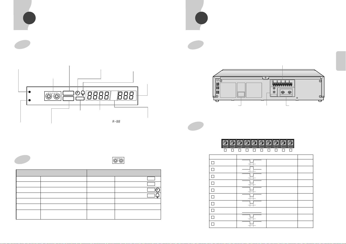
CONNECTORS
FRONTSIDE
REC LOCK lamp
• Lights during record
locking mode.
Recording display
• Lights during
recording.
Tape presence and
operation display
Tape End display
• Lights when VCR
reaches end of tape.
HIGH PICTURE
• Lights during
high picture
mode.
DISPLA Y OF OPERATING CONDITIONS
Playback Rotates clockwise
Still Blinking
Slow Playback Blinking and rotating clockwise
Forward Search Rotates rapidly clockwise
Reverse Search Rotates rapidly counterclockwise
Reverse Playback Rotates counterclockwise
Reverse Slow Blinking and rotates slowly
Playback counterclockwise
7
Power failure return
display
• Flashes upon return of
AC power.
• Pressing any button
turns off.
Play back display
Reserve timer recording
display
• Lights after programming
Recording Rotates clockwise
Pause Blinking
Timer Recording Rotates clockwise
Alarm Recording Rotates clockwise
Rewinding Rotates rapidly counterclockwise
Fast Forwarding Rotates rapidly clockwise
Alarm recording display
• Lights during alarm
timer recording.
Counter display
• Operating hour display.
• Alarm/Counter memory
display.
""
Display other than playback
recording and flickers
upon completion of
recording.
REC/PLAYTime
mode display.
Alarm/Counter
Memory display
• Counter Memory:
C. MEMO.
• Alarm Memory:
A. MEMO.
• Operating hour
display: HOUR.
REAR SIDE
EXTERNAL EQUIPMENT TERMINAL
POWER PLUG SLOT
AUDIO IN/OUTPUT JACK
(RCATYPE)
VIDEO IN/OUTPUT JACK
(BNC TYPE)
EXTERNAL EQUIPMENT TERMINAL INFORMA TION
TERMINAL NAME SIGNAL LEVEL TYPE
VIH : 4 ~ 5V
VIL : 0 ~ 0.6 V
T : More than 0.5 second
VIH : 4 ~ 5V
VIL : 0 ~ 0.6 V
T : Alarm Recording
VIH : 4 ~ 5V
VIL : 0 ~ 0.6 V
T : More than 0.5 second
VIH : 4 ~ 5V
VIL : 0 ~ 0.6 V
T:
VIH : 4 ~ 5V
VIL : 0 ~ 0.6 V
T : More than 8m sec
VIH : 4 ~ 5V
VIL : 0 ~ 0.6 V
T : During input any button
VIH : 4 ~ 5V
VIL : 0 ~ 0.6 V
T : More than 1 second
0V
VIH : 4 ~ 5V
VIL : 0 ~ 0.6 V
T : More than 0.5 second
VIH : 4 ~ 5V
VIL : 0 ~ 0.6 V
T : More than 0.5 second
OUTPUT
OUTPUT
OUTPUT
OUTPUT
OUTPUT
INPUT
INPUT
GND
INPUT
INPUT
8
ATION
ATION
CONFIGUR-
CONFIGUR-
SET UP
RS-232C
IN
IN OUT
OUT
AUDIO
VIDEO
1
6
ALARM IN
TAPE END OUT
2
7
ALARM OUT
SERIES OUT
3
8
ALARM RESET
GND
4
9
ERROR OUT
SERIES IN
5
10
TRIGGER OUT
1 SHOT RECIN
1 2 3 4 5 6 7 8 9101 2 3 4 5 6 7 8 9
10
IN
IN OUT
OUT
AUDIO
VIDEO
RS-232C
IN
IN OUT
OUT
AUDIO
VIDEO
1
6
ALARM IN
TAPE END OUT
2
7
ALARM OUT
SERIES OUT
3
8
ALARM RESET
GND
4
9
ERROR OUT
SERIES IN
5
10
TRIGGER OUT
1 SHOT RECIN
1 2 3 4 5 6 7 8 9101 2 3 4 5 6 7 8 9
10
IN OUT
VIDEO
6 7 8 9
RS-232C
IN
IN OUT
OUT
AUDIO
VIDEO
1
6
ALARM IN
TAPE END OUT
2
7
ALARM OUT
SERIES OUT
3
8
ALARM RESET
GND
4
9
ERROR OUT
SERIES IN
5
10
TRIGGER OUT
1 SHOT RECIN
1 2 3 4 5 6 7 8 9101 2 3 4 5 6 7 8 9
10
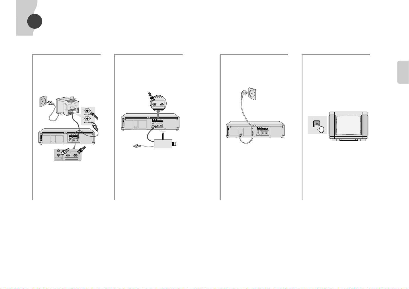
POWER
• Check the following preparations before using this unit.
• The shape of the real power plug may be different from the shape in the manual.
Make a connection
1
between the monitor and
this unit.
MONITOR
VIDEO INPUT
Connect the CCD camera
2
to this unit.
CCD CAMERA
Insert the power plug of
3
this unit video into the wall
outlet.
• Insert the plug into AC100~240V
working outlet.
AC100~240V
Turn on the power of the
4
monitor.
• If using a monitor turn on power.
• If using a TV, turn on power and switch
to video input.
• Refer to the operating instructions for
further details on TV.
ATION
ATION
CONFIGUR-
CONFIGUR-
10
9
HOW TO SET MENU
To select a menu item
2
press the SHIFT
(The "❿" sign will move down once
with each press)
❷
button
Press the MENU button
(Does not display while in play mode
1
or until the time has been set.)
MENU
MAIN MENU
1
❿
CLOCK SET/ADJUST
2 DISPLAYMODE SETUP
3 ALARM REC SETUP/RECALL
4 REC MODE SETUP
5 VCR MODE SETUP
6 PROGRAM SETUP
7 POWER LOSS MEMORY
(
❷
) END:MENU
❿
After positioning " ❿" sign
3
to the desired menu item,
press the SHIFT
❿
to proceed.
• Displays the selected menu on the
screen.
(Refer to 13~20 page)
button
1. CLOCK SET/ADJUST
CLOCK SET/ADJUST
❿
SUMMER TIME SET (USE)
1
2 DISPLAYMODE (YY-MM-DD)
3 CLOCK SET/ADJUST
YEAR DATE TIME
2001 01/01 MON 12:00
$
(
❷
/–+) END:MENU
❿
2. DISPLAY MODE SETUP
DISPLAYMODE SETUP
❿
DATE DISPLAY ------------------(ON)
1
2 TIME DISPLAY-------------------(ON)
3 POSITION -------------(R-BOTTOM)
(
❷
) END:MENU
❿
• Set desired time date format and on
screen location.
3. ALARM REC SETUP
ALARM REC SETUP/RECALL
1
❿
MODE -----------------------------(L8H)
2 DURATION--------------------(AUTO)
3 BUZZER ---------------------------(ON)
4 ALARM RECALL
(
❷
/–+) END:MENU
❿
• Select Alarm REC Mode.
4. REC MODE SETUP
REC MODE SETUP
❿
REC TIME MODE--------------(L8H)
1
2 REPEATREC-------------------(OFF)
3 SERIES REC -------------------(OFF)
4 1-SHOT REC--------------------(OFF)
(
❷
) END:MENU
❿
• Set the repeat record mode. 1-shot
record mode and series record mode.
5. VCR MODE SETUP
VCR MODE SETUP
1
❿
TRIGGER--------------------(1FIELD)
2 V-SYNC----------------------------(ON)
3 BUZZER ---------------------------(ON)
4 TAPE LENGTH----------------(E240)
(
❷
) END:MENU
❿
• Trigger out timing control and
beeper sound control.
MENU
6. PROGRAM SETUP
PROGRAM SETUP1
START STOP DATE MODE
❿
•
•
•
•
•
PROGRAM SETUP2
•
(
❷
/–+,CLEAR) END:MENU
❿
PROGRAM SETUP2
*
START STOP DATE MODE
❿
•
•
•
•
•
PROGRAM SETUP1
•
(
❷
/–+,CLEAR) END:MENU
❿
• Select the program record.
7. POWER LOSS MEMORY
*
POWER LOSS MEMORY
YEAR DATE TIME
OFF
•
ON
OFF
•
ON
OFF
•
ON
END:MENU
• Displays power failure and restore
history.
11
12

14
MENU
13
SETTING CURRENT TIME
1
Example) December 25 . 2002 13:30
Press the MENU button.
•When pressing the MENU button,
the MAIN MENU displays.
2
Press the SHIFT ❿!button.
•When pressing the SHIFT
❿❿!
button,
CLOCK SET/ADJUST displays.
MAIN MENU
1
❿
CLOCK SET/ADJUST
2 DISPLAY MODE SETUP
3 ALARM REC SETUP/RECALL
4 REC MODE SETUP
5 VCR MODE SETUP
6 PROGRAM SETUP
7 POWER LOSS MEMORY
(
❷
❿
) END:MENU
CLOCK SET/ADJUST
1
❿
SUMMER TIME SET (USE)
2 DISPLAY MODE(YY-MM-DD)
3 CLOCK SET/ADJUST
YEAR DATE TIME
2001 01/01 MON 12:00
$
(
❷
❿
/–+) END:MENU
– HOW TO SET THE SUMMER TIME
5
Set the week, day, month
and time using the
TRACKING/ SET
buttons.
•
Press the SHIFT
❿❿!
button after
setting the week, then
$
sign will
place under the day.
•The month and time work in the
same way.
6
Press the SHIFT ❷!button
and set the SUMMER TIME
OUT.
3
Press the SHIFT ❿!button.
•When pressing the SHIFT
❿❿
button,
the SUMMER TIME SET displays.
•Press the SHIFT
❿❿!
button to toggle
the summer time USE or NO USE.
4
Press the SHIFT ❷!button.
•
Select the SUMMER TIME IN.
SUMMER TIME SET
1
❿
SUMMER TIME (USE)
2 SUMMER TIME IN
3 SUMMER TIME OUT
WEEK MONTH TIME
IN LAST /FRI 2 9:00
OUT FIRST /
SUN
12 12:00
(
❷
❿
/–+) END:MENU
7
Press the MENU button.
•
Check the week, day, month and
time again and press the MENU
button.
SUMMER TIME SET
1 SUMMER TIME (USE)
2
❿
SUMMER TIME IN
3 SUMMER TIME OUT
WEEK MONTH TIME
IN LAST /FRI
11
14:00
$
(
❷
❿
/–+) END:MENU
SUMMER TIME SET
1 SUMMER TIME (USE)
2
❿
SUMMER TIME IN
3 SUMMER TIME OUT
WEEK MONTH TIME
IN LAST /FRI
11
14:00
$
(
❷
❿
/–+) END:MENU
SUMMER TIME SET
1 SUMMER TIME (USE)
2 SUMMER TIME IN
3
❿
SUMMER TIME OUT
WEEK MONTH TIME
OUT FIRST /
SUN
12 12:00
$
(
❷
❿
/–+) END:MENU
CLOCK SET/ADJUST
1
❿
SUMMER TIME SET (USE)
2 DISPLAY MODE(YY-MM-DD)
3 CLOCK SET/ADJUST
YEAR DATE TIME
2001 01/01 MON 12:00
$
(
❷
❿
/–+) END:MENU
8
Press the SHIFT ❷button and
press the SHIFT
❿
button.
•Whenever pressing the SHIFT
❿❿
button, the display mode changes.
•The display changes as following.
(YY-MM-DD)
➝ (DD-MM-YY) ➝
(MM-DD-YY)
CLOCK SET/ADJUST
1 SUMMER TIME SET (USE)
2
❿
DISPLAYMODE(YY-MM-DD)
3 CLOCK SET/ADJUST
YEAR DATE TIME
2001 01/01 MON 12:00
$
(
❷
❿
/–+) END:MENU
– HOW TO SET THE DISPLAY MODE
MENU
TRACKING/SET
SHIFT
V-LOCK
SHIFT
V-LOCK
SHIFT
V-LOCK
MENU
SHIFT
V-LOCK
SHIFT
V-LOCK
 Loading...