

SAMSUNG SVB120XKXEG Service Manual
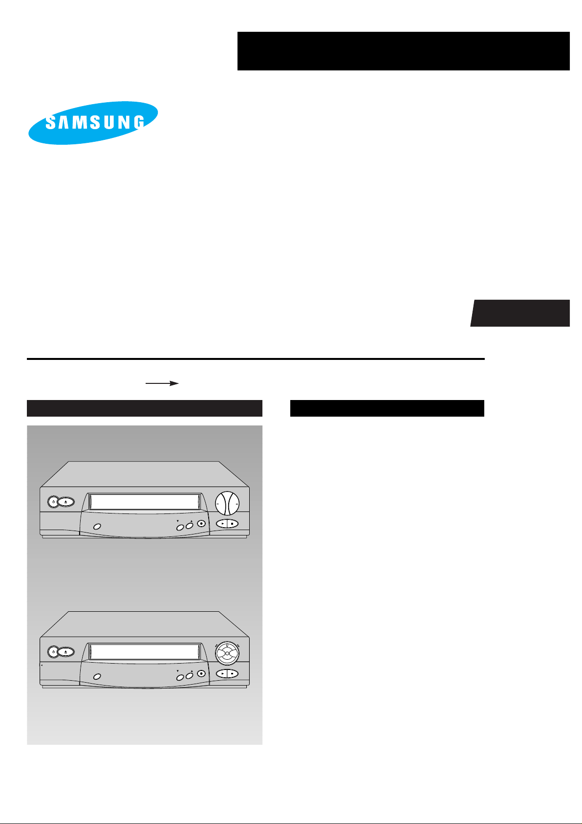
VIDEO CASSETTE RECORDER
SV-610X/210X
SV-614B/210B
SV-480G/470G
SERVICE
PLAY
REC
SYSTEM
REW
F.F
POWER EJECT
PROGRAM
STOP
OPEN
PLAY
REC
SYSTEM
POWER EJECT
PROGRAM
STOP
REW F.F
SV-480G
SV-610X/210X/614B/210B/470G
Manual
VIDEO CASSETTE RECORDER CONTENTS
For mechanical disassembly and adjustment, refer to the “Mechanical Manual”
(DX7-A/AC, DX8-A/AC AC68-20392A).
1. Precautions
2. Reference Information
3. Product Specifications and
Comparison Chart
4. Disassembly and Reassembly
5. Alignment and Adjustment
6. Exploded View and Parts List
7. Electrical Parts List
8. Block Diagrams
9. PCB Diagrams
10. Wiring Diagram
11. Schematic Diagrams

© Samsung Electronics Co., Ltd. JUN. 1998
Printed in Korea
AC68-20417A
ELECTRONICS
SERVICE MANUAL SV-610X/210X/614B/210B/480G/470G
Application Data Page Part # Note(Cause & Solution) S/Bulletin #
UPDATE LOG SHEET
Use this page to keep any special servicing information. (Service Bulletin, etc.)
If only parts number changes, Just change parts number directly on parts list.
And if you need more information, please see the service bulletin
Samsung Electronics 1-1
1. Precautions
1. Be sure that all of the built-in protective devices are
replaced. Restore any missing protective shields.
2. When reinstalling the chassis and its assemblies, be
sure to restore all pretective devices, including :
control knobs and compartment covers.
3. Make sure that there are no cabinet openings
through which people--particularly children
--might insert fingers and contact dangerous
voltages. Such openings include the spacing
between the picture tube and the cabinet mask,
excessively wide cabinet ventilation slots, and
improperly fitted back covers.
If the measured resistance is less than 1.0 megohm
or greater than 5.2 megohms, an abnormality exists
that must be corrected before the unit is returned
to the customer.
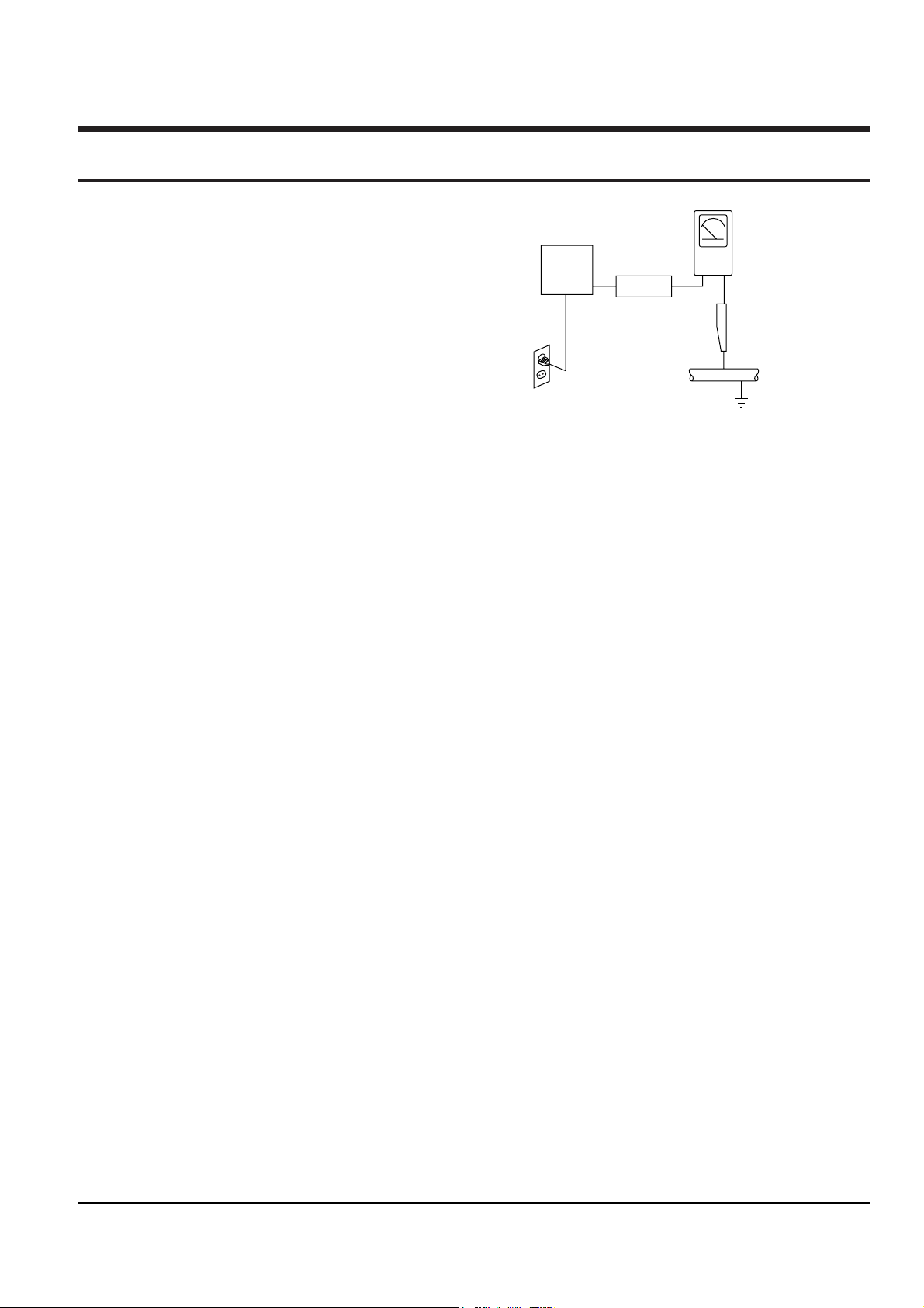
4. Leakage Current Hot Check (See Fig. 1) :
Warning : Do not use an isolation transformer
during this test. Use a leakage current tester or a
metering system that complies with American
National Standards Institute (ANSI C101.1,
Leakage Current for Appliances), and Underwriters
Laboratories (UL Publication UL1410, 59.7).
5. With the unit completely reassembled, plug the AC
line cord directly the power outlet. With the unitÕs
AC switch first in the ON position and then OFF,
measure the current between a known erath
ground (metal water pipe, conduit, etc.) and all
exposed metal parts, including : antennas, handle
brackets, metal cabinets, screwheads and control
shafts. The current measured should not exceed
0.5 milliamp. Reverse the power-plug prongs in the
AC outlet and repeat the test.
6. X-ray Limits :
The picture tube is designed to prohibit X-ray
emissions. To ensure continued X-ray protection,
replace the picture tube only with one that is the
same type as the original.
Fig. 1-1 AC Leakage Test
7. Antenna Cold Check :
With the unitÕs AC plug disconnected from the
AC source, connect an electrical jumper across the
two AC prongs. Connect one lead of the ohmmeter
to an AC prong.
Connect the other lead to the coaxial connector.
8. High Voltage Limit :
High voltage must be measured each time
servicing is done on the B+, horizontal deflection
or high voltage circuits.
Heed the high voltage limits. These include the
X-ray protection Specifications Label, and the
Product Safety and X-ray Warning Note on the
service data schematic.
9. Some semiconductor (Òsolid stateÓ) devices are
easily damaged by static electricity.
Such components are called Electrostatically
Sensitive Devices (ESDs); examples include
integrated circuits and some field-effect transistors.
The following techniques will reduce the
occurrence of component damage caused by static
electricity.
10. Immediately before handling sny semiconductor
components or assemblies, drain the electrostatic
charge from your body by touching a known
earth ground. Alternatively, wear a discharging
Wrist-strap device. (Be sure to remove it prior to
applying power--this is an electric shock
precaution.)
Device
Under
Test
(Reading should
not be above
0.5mA)
Leakage
Currant
Tester
Earth
Ground
Test all
exposed metal
surfaces
Also test with
plug reversed
(using AC adapter
plug as required)
2-Wire Cord

Precautions
1-2 Samsung Electronics
11. High voltage is maintained within specified limits
by close-tolerance, safety-related components and
adjustments. If the high voltage exceeds the
specified limits, check each of the special
components.
12. Design Alteration Warning :
Never alter or add to the mechanical or electrical
design of this unit. Example : Do not add
auxiliary audio or video connectors. Such
alterations might create a safety hazard. Also, any
design changes or additions will void the
manufacturerÕs warranty.
13. Hot Chassis Warning :
Some TV receiver chassis are electrically
connected directly to one conductor of the AC
power cord. If an isolation transformer is not
used, these units may be safely serviced only if
the AC power plug is inserted so that the chassis
is connected to the ground side of the AC source.
To confirm that the AC power plug is inserted
correctly, do the following : Using an AC
voltmeter, measure the voltage between the
chassis and a known earth ground. If the reading
is greater than 1.0V, remove the AC power plug,
reverse its polarity and reinsert. Re-measure the
voltage between the chassis and ground.
14. Some TV chassis are designed to operate with 85
volts AC between chassis and ground, regardless
of the AC plug polarity. These units can be safely
serviced only if an isolation transformer inserted
between the receiver and the power source.
15. Never defeat any of the B+ voltage interlocks.
Do not apply AC power to the unit (or any of its
assemblies) unless all solid-state heat sinks are
correctly installed.
16. Always connect a test instrumentÕs ground lead to
the instrument chassis ground before connecting
the positive lead; always remove the instrumentÕs
ground lead last.
17. Observe the original lead dress, especially near
the following areas : Antenna wiring, sharp
edges, and especially the AC and high voltage
power supplies. Always inspect for pinched, outof-place, or frayed wiring. Do not change the
spacing between components and the printed
circuit board. Check the AC power cord for
damage. Make sure that leads and components
do not touch thermally hot parts.
18. Picture Tube Implosion Warning :
The picture tube in this receiver employs
Òintegral implosionÓ protection. To ensure
continued implosion protection, make sure that
the replacement picture tube is the same as the
original.
19. Do not remove, install or handle the picture tube
without first putting on shatterproof goggles
equipped with side shields. Never handle the
picture tube by its neck. Some Òin-lineÓ picture
tubes are equipped with a permanently attached
deflection yoke; do not try to remove such
Òpermanently attachedÓ yokes from the picture
tube.
20. Product Safety Notice :
Some electrical and mechanical parts have special
safety-related characteristics which might not be
obvious from visual inspection. These safety
features and the protection they give might be
lost if the replacement component differs from the
original--even if the replacement is rated for
higher voltage, wattage, etc.
Components that are critical for safety are
indicated in the circuit diagram by shading,
( or ).
Use replacement components that have the same
ratings, especially for flame resistance and
dielectric strength specifications. A replacement
part that does not have the same safety
characteristics as the original might create shock,
fire or other hazards.
Samsung Electronics 2-1
2. Reference Information
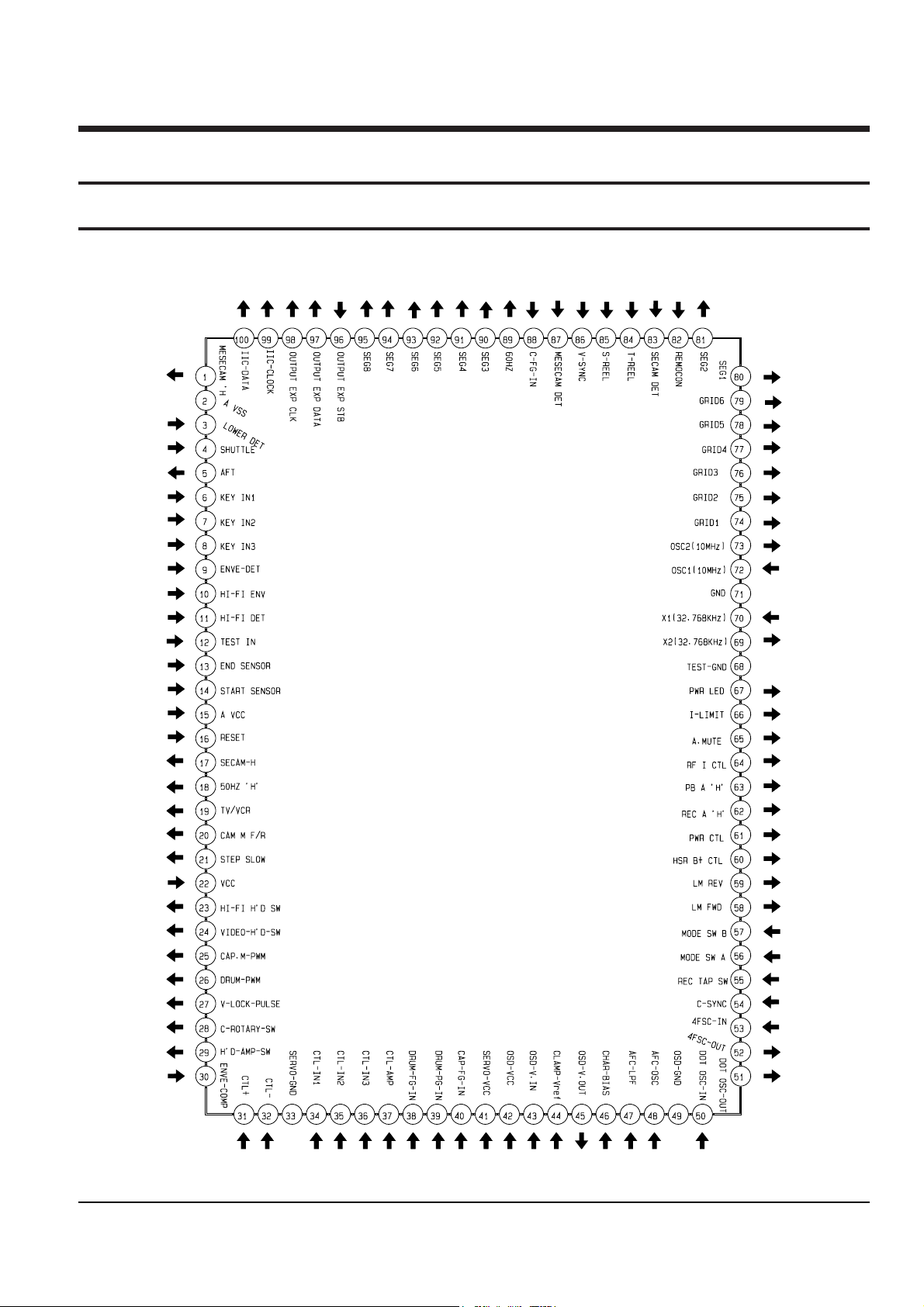
2-1 IC BLOCK
2-1-1 IC601 (HD6433977)
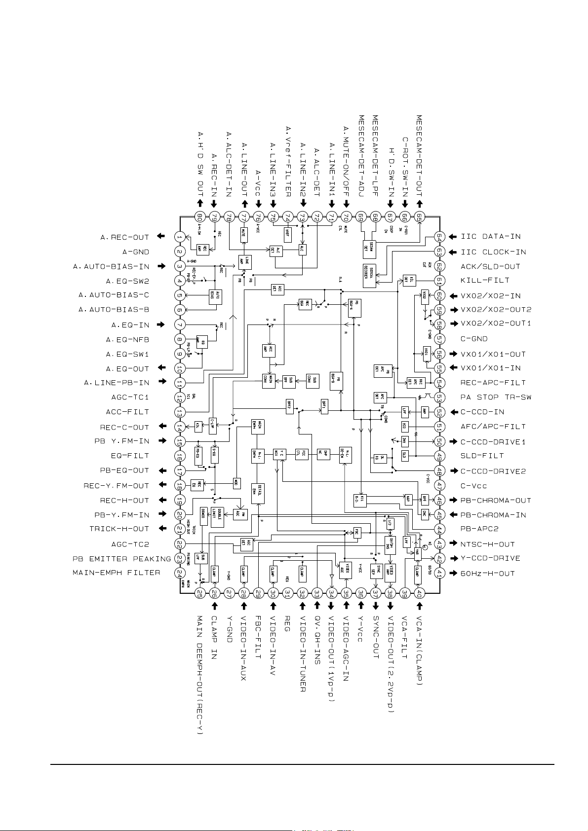
Reference Information
2-2 Samsung Electronics
2-1-2 IC301 (SS11511M)
Reference Information
Samsung Electronics 2-3
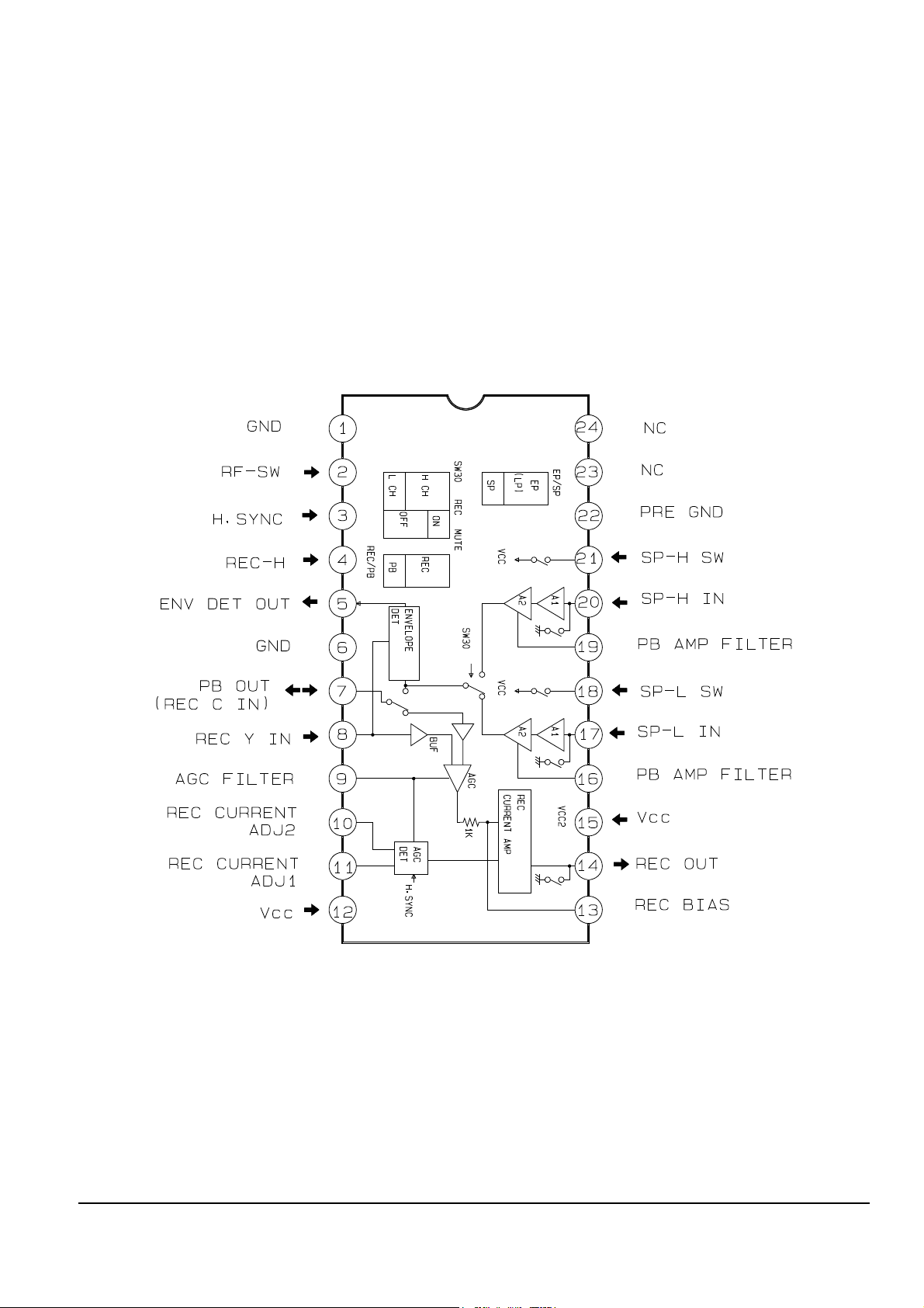
2-1-3 IC302 (LA7411) - 2Head
Reference Information
2-4 Samsung Electronics
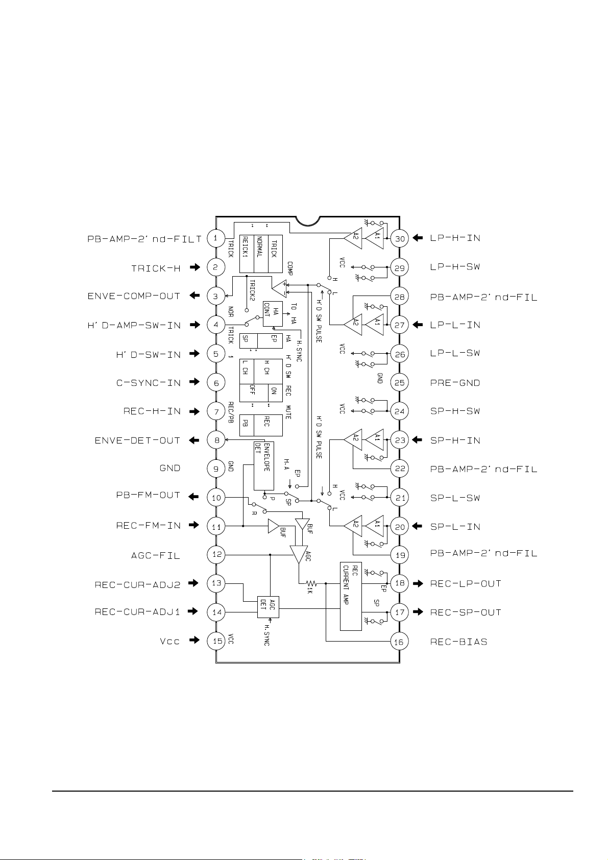
2-1-4 IC302 (LA7416) - 4Head

Reference Information
Samsung Electronics 2-5
2-1-5 IC501 (LA72633) - Only for SV-610X/614B

Reference Information
2-6 Samsung Electronics
MEMO
Samsung Electronics 3-1
3. Product Specifications and Comparison Chart
3-1 Product Specifications
Operation Description
Format VHS PAL standard
Heads Video : 4 or 2 rotary heads
Audio/Control : 1 stationary head
Hi-Fi : 2rotary heads
Erase : 1 full track erase head
Receiving channel VHF-I, VHF-III, UHF, Hyperband
Television system Standard B/G (for German)
Standard I (for U.K)
Standard B/G, D/K (for East Europe)
Recording system
Luminance FM azimuth recording
Colour
PAL (NTSC/MESECAM) : Down converted subcarrier phase shifted direct recording
NTSC PB on PAL TV
Tape speed SP : 23.39 mm/sec, LP : 11.69 mm/sec
Recording/playback time SP : 3 hours (E-180 Tape), LP : 6 hours (E-180 Tape)
F.F/REW time About 100 ~ 190 sec in REW/F.F with E-180 tape
VIDEO
Input 0.5 to 2.0 Vp-p : 75 ohm unbalanced
Output 1.0 ± 0.2 Vp-p : 75 ohm unbalanced
Signal-to-noise ratio Better than 43 dB (SP)
Horizontal resolution More than 240 lines (SP)
Audio
Input -8 dBm, 47 Kohm unbalanced
Output -8 ± 3 dBm, 1 Kohm unbalanced
Wow and flutter (WTD) 0.4% max (SP)
Signal-to-noise ratio Hi-Fi : 68dB min (IHF A filter), Mono : 42 dB min (IHF filter)
Frequency response Hi-Fi : 20Hz ~ 20KHz, Mono : 100Hz ~ 8KHz
Power requirement 230V (AC 50/60 Hz)
Power consumption Hi-Fi : Approx. 21 watts Mono : Approx. 18 watts
Operation temperature 41°F ~ 104°F (5°C ~ 40°C)
Operation humidity 10%-75%
Weight 4.4 Kg (net)
Dimensions (W x H x D) 360 x 92 x 314 mm
Design and specifications are subject to change without notice.
Product Specifications
3-2 Samsung Electronics
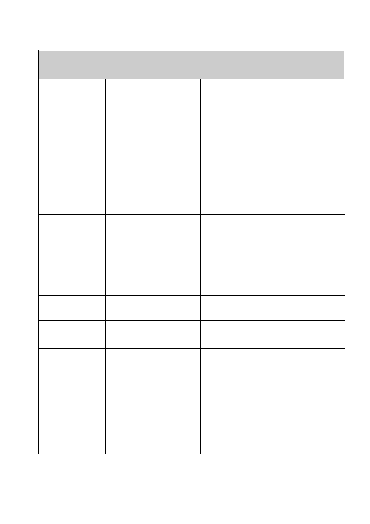
3-2 Comparison Chart
COUNTRY MODEL HEADS
TAPE SPEED
A2 NICAM S/VIEW V/PLUS VPS PDC ATS
CANAL+ P/MIERE VCR/TV
GERMANY SV-610X 4 (Hi-Fi) SP/LP O X O X O X O X X X X
SV-210X 2 SP X X O X O X O X X X X
U.K SV-614B 4 (Hi-Fi) SP/LP X O X O X O O X X X X
SV-210B 2 SP/LP X X X X X O O X X X X
POLAND SV-480G 4
(Mono)
SP/LP X X O X O X O X X X O
SV-470G 4
(Mono)
SP/LP X X X X X X X X X X O
DIAMOND HEAD
(DLC)
Samsung Electronics 4-1
4. Disassembly and Reassembly
4-1 Cabinet Assembly
Note : Disassemble in the order shown.
Reassemble in reverse order.
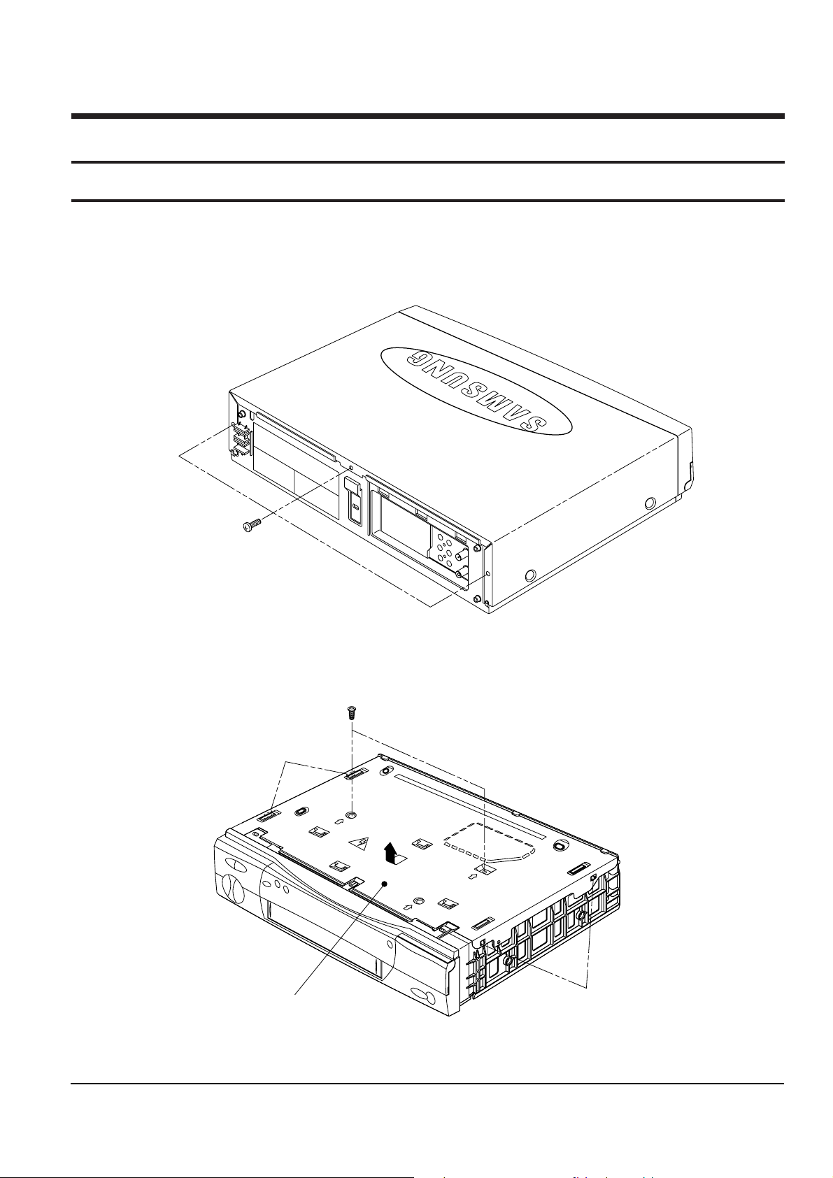
4-1-1 Cabinet Top removal
ΠREMOVE 3 SCREWS
(BH;3-4X16-BLACK)
Fig. 4-1 Cabinet Top removal
4-1-2 Bottom cover removal
ΠREMOVE 2 SCREWS
(BH;2-3X10-YELLOW)
´ RELEASE 2 SNAPFITS
´ RELEASE 2 SNAPFITS
ˇ Lift up the bottom cover
in the direction of arrow.
Fig. 4-2 Bottom Cover removal
Disassembly and Reassembly
4-2 Samsung Electronics
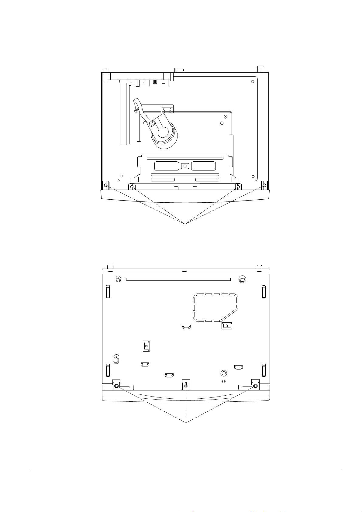
4-1-3 Ass’y Front Panel removal
(Bottom view)
ΠRELEASE 4 HOOKS
´ RELEASE 3 HOOKS
(Top view)
Fig. 4-3 Ass’y Front Panel removal
Disassembly and Reassembly
Samsung Electronics 4-3
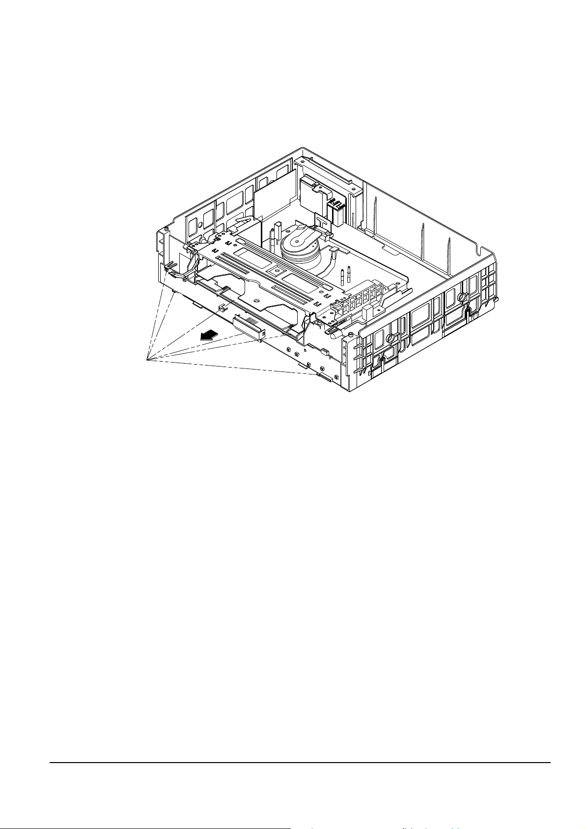
4-1-4 Ass’y Function-Timer removal
Note : Take extreme care not to damage the PCB when removing it.
ΠRELEASE 6 TABS
Fig. 4-4 Ass’y Function-Timer removal
Note : 1. When removing chassis, take extreme care not to damage the main PCB front.
2. When reinstalling the deck on the main PCB, take extreme care not to damage the sensor.
Disassembly and Reassembly
4-4 Samsung Electronics
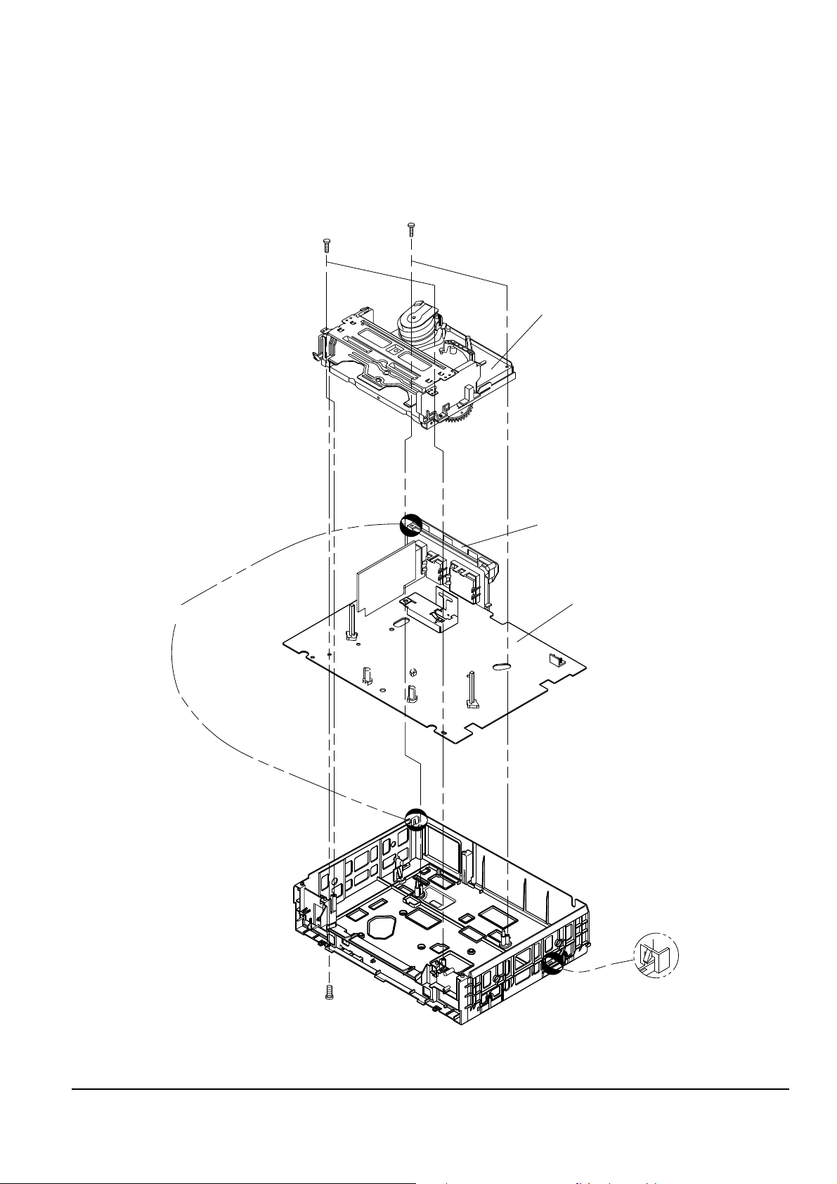
4-1-5 Chassis removal
Fig. 4-5 Chassis Removal
ΠREMOVE 2 SCREWS
(BH;2-3X12-YELLOW) ´ REMOVE 2 SCREWS
(BH;2-4X12-YELLOW)
¨ Lift the ass'y full deck up.
CONNECTOR BOARD-ASS'Y
ˇ REMOVE 1 SCREW
(BH;3X12-YELLOW)
ˆ RELEASE 1 TAB
Ø RELEASE 1 TAB
∏ Lift the ass'y main up to remove.
Disassembly and Reassembly
Samsung Electronics 4-5
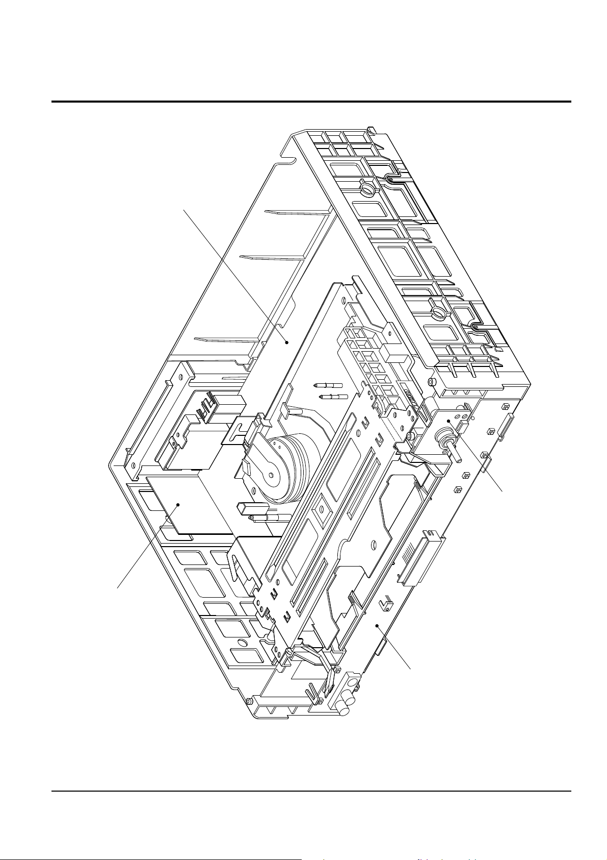
4-2 Circuit Board Locations
MAIN BOARD
FUNCTION-TIMER BOARD
SUB BOARD-A2/NICAM
(SV-610X/614B ONLY)
SHUTTLE BOARD
Fig. 4-6 Circuit Board Locations

Disassembly and Reassembly
4-6 Samsung Electronics
MEMO
Samsung Electronics 5-1
5. Alignment and Adjustment
Note : After replacing the assÕy full deck, the assÕy main, the cylinder assÕy and the micom(IC601), the remote
control assÕy can be used to adjust the ÒX-point (tracking center) adjustmentÓ and ÒHead S/W pointÓ
adjustment.
5-1 Reference
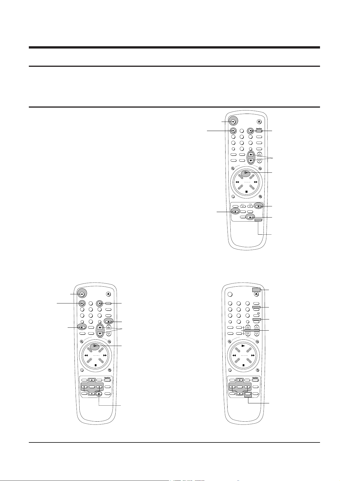
5-1-1 The type of remote control ass’y
1. Remote control assÕy (AC93-10039Y/69099-633-252)
is specified as a service jig in the service manual of
X-5/X-6(DX5-R/DX5-RC/DX6-R/DX6-RC) chassis.
(See Fig. 5-1)
2. Normal remote control assÕy for X-7/X-8
(DX7-R/DX7-RC/DX8-R/DX8-RC) chassis.
(See Fig. 5-2)
5-1-2 How to identify between normal
remote control ass’y and multi
remote control ass’y for X-7/X-8
chassis (See Fig. 5-2)
1. The color of some buttons related to TV function are
gold.
2. Audio button is added instead of the test button
hidden behind of inlay.
3. The positions of some buttons are different.
EJECT
2
456
789
0
CLK/COUNT
REW
F.F
STOP
CLR/RST DISPLAY
Q-PRO
MENU
S
H
I
F
T
S
H
U
T
T
L
E
DAILY WEEKLY
REC
P/S
PRESET BAND
SEARCH MEMORY
OUTPUT
INDEX SLOW INPUT
INPUT BUTTON
SP/LP BUTTON
SP LP A.DUB VPS
FINE CH
TRK
(TRACKING, FINE)
BUTTON
POWER BUTTON
POWER
PLAY BUTTON
PLAY
TEST BUTTON IS
HIDDEN BEHIND
OF INLAY.
3
HEAD S/W ADJ.
("INPUT" OR "TEST"
AND "3" BUTTON)
1
TRACKING
CENTER ADJ.
("INPUT" OR "TEST"
AND "1" BUTTON)
633-252
REMOTE CONTROL
ASS'Y PART NO.
Fig. 5-1 Remote Control Ass’y Jig for X-5/X-6 Chassis
(AC93-10039Y/69099-633-252)
EJECT
2
456
789
0
CLK/COUNT
REW
F.F
STOP
AUDIO
DISPLAY
REC
P/S
INDEX A.TRK
INPUT BUTTON
FINE PROG
TRK
(TRACKING, FINE)
BUTTON
POWER BUTTON
POWER
PLAY BUTTON
PLAY
TEST BUTTON IS
HIDDEN BEHIND
OF INLAY.
3
HEAD S/W ADJ.
("INPUT" OR "TEST"
AND "3" BUTTON)
1
TRACKING
CENTER ADJ.
("INPUT" OR "TEST"
AND "1" BUTTON)
SYSTEM
CLR/RST
S
H
U
T
T
L
E
SPEED BUTTON
SPEED AFT
INPUT
TV/VCR
PICTURE
A.DUB
2
456
789
0
CLK/COUNT
REW
F.F
STOP
DISP./
REC
P/S
INDEX
VCR
POWER
PLAY
3
1
VCR
CLR/RST
S
H
U
T
T
L
E
SPEED
TV/VCR
PICTURE
A.DUB
NORMAL REMOTE CONTROL ASS'Y
(CAN ADJUST)
MULTI REMOTE CONTROL ASS'Y
(CAN NOT ADJUST)
-/--
FINE
AUDIO
ADD BUTTON(AUDIO)
GOLD COLOR
TV
GOLD COLOR
TV
POWER
INPUT
GOLD COLOR
VOLUME PROG
GOLD COLOR
MENU
Q-PRO
SLOW
SOFTEN OK SHARPEN
MENU
Q-PRO
SLOW
SOFTEN OK SHARPEN
Fig. 5-2 Remote Control Ass’y for X-7/X-8 Chassis
Alignment and Adjustment
5-2 Samsung Electronics
5-2 Mechanical Adjustment
Note : Refer to the Mechanical Manual ÒDX7-A/DX7-AC/DX8-A/DX8-AC (AC68-20392A)Ó for the adjustment
and confirmation of assÕy full deck.
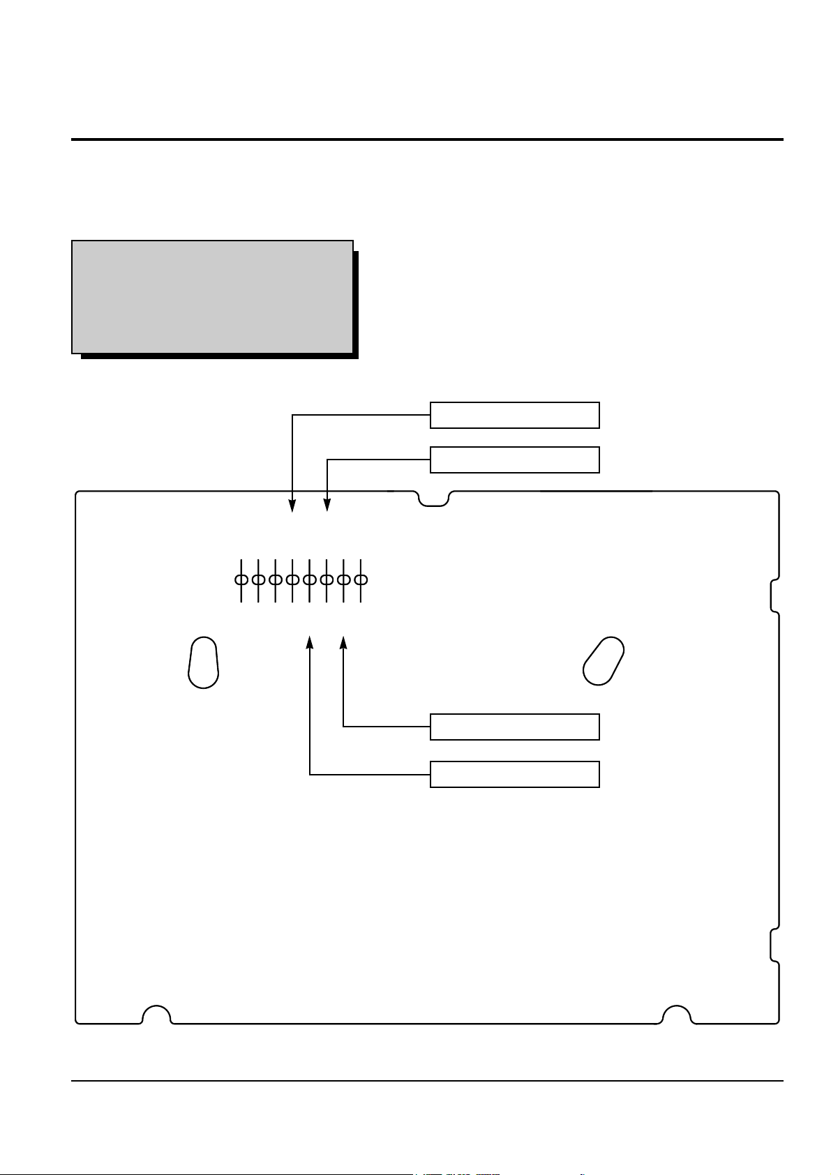
5-2-1 The number and position of test point
GND
CTL
TP01
H'D SW
V.ENV
A.OUT
V.OUT
AGC
SCART CTL
TP02
TP03
TP04
TP05
TP06
TP07
TP08
Fig. 5-3 The position of test point (Main PCB-Component side)
Test point : TP02 (CTL Pulse)
TP03 (H’D S/W -Trigger)
TP04 (V. Envelope)
TP05 (Audio out)
CTL PULSE
V. ENVELOPE
AUDIO OUT
H’D S/W -TRIGGER

Alignment and Adjustment
Samsung Electronics 5-3
5-2-2 X-Point(Tracking center) adjustment
(See the 2-2-1 (d) AC HEAD
POSITION(X-POINT) ADJUSTMENT
on page 2-3 of the mechanical
manual)
5-2-2 (a) IF THE REMOTE CONTROL ASS’Y IS
NOT AVAILABLE
1. Playback the colorbar alignment tape.
2. Connect CH-1 scope probe to ÒTP02Ó and CH-2
scope probe to ÒTP03Ó. And then, trigger head
switching pulse.
3. Set tracking preset to 11msec (2head : 2.7msec,
4, 6head : 11msec) using the ÒFINE (ADJUST)
button / of the other remote control
assÕy except the remote control assÕy jig for X-5/
X-6 chassis and the normal remote control assÕy for
X-7/X-8 chassis.
4. Insert the adjusting driver (+) into X-position
adjusting gear. Adjust the driver in either direction
for maximum envelope waveform.
Note :
Since the adjusting gear unit may be damaged, do
not adjust by force when adjusting the X-point using the
adjusting driver (+). After turn the X-point adjusting screw
(D) counterclockwise a little, perform the adjustment.
After adjustment is completed, tighten the screw.
5-2-2 (b) IF THE REMOTE CONTROL ASS’Y
(AC93-10039Y/69099-633-252) IS
AVAILABLE
Note : How to use the ÒTESTÓ button.
1. Disattach the inlay of remote control assÕy.
(See Fig. 5-1 and Fig. 5-2)
2. Press the ÒTESTÓ button with the pincers and the
precise driver as shown in Fig. 5-1 and 5-2)
1. When using the ÒINPUTÓ button of remote
control assÕy;
1) Simultaneously press the ÒINPUTÓ button and Ò1Ó
button in PB mode.
This will adjust the tracking center automatically.
2) Set the tracking preset using the ÒFINE (ADJUST)
button of remote control.
3) After adjustment is completed, press the
ÒPOWERÓ button to release.
2. When using the ÒTESTÓ button of remote
control assÕy ;
1) Simultaneously press the ÒTESTÓ button and Ò5Ó
button in PB mode.
This will adjust the tracking center automatically.
2) Set the tracking preset using the ÒFINE (ADJUST)
button of remote control.
3) After adjustment is completed, press the
ÒPOWERÓ button to release.
<Setting of scope>
- Volt/div. : CH-1 = 0.1V - Time/div. : 5msec
CH-2 = 0.2V
Fig. 5-4 Tracking preset adjustment
Fig. 5-5 Tracking preset adjustment
SCREW(C)
TILT ADJUST
X-POSITION
ADJUST GEAR
HOLE
SCREW(A)
HEIGHT ADJUST
SCREW(B)
AZIMUTH ADJUST
SCREW(D)
X-POINT LOCKING
Fig. 5-6 Location of A/C Head adjustment screw
2.7msec (2 Head), 11msec (4, 6 Head)
CH-2 Probe
TP02
H'D S/W Pulse
CH-1 Probe
TP03
CTL Pulse
REMOTE
BUTTONS
CONTROL PULSE REMOVE
FINE
FINE
PUSH
PUSH

Alignment and Adjustment
5-4 Samsung Electronics
5-2-2 (b) IF THE NORMAL REMOTE CONTROL
ASS’Y OF X-7/X-8(DX7-R/DX7-RC/
DX8-R/DX8-RC) CHASSIS IS
AVAILABLE
Note 1 : Two kinds of remote control assÕy are used
for X-7/X-8(DX7-R/DX7-RC/DX8-R/
DX8-RC) chassis.
1. One is a normal remote control assÕy, the other is a
multi remote control assÕy
2. All adjustments are adjusted by normal remote
control assÕy only.
3. For the identification of normal remote control
assÕy and multi remote control assÕy, See page 5-1.
Note 2 : How to use the ÒTESTÓ button.
1. Disattach the inlay of remote control assÕy.
(See Fig. 5-1 and Fig. 5-2)
2. Press the ÒTESTÓ button with the pincers and the
precise driver as shown in Fig. 5-1 and 5-2)
1. When using the ÒINPUTÓ button of remote
control assÕy;
1) Simultaneously press the ÒINPUTÓ button and Ò1Ó
button in PB mode.
This will adjust the tracking center automatically.
2) Set the tracking preset using the ÒFINE (ADJUST)
button of remote control.
3) After adjustment is completed, press the
ÒPOWERÓ button to release.
2. When using the ÒTESTÓ button of remote
control assÕy ;
1) Simultaneously press the ÒTESTÓ button and Ò5Ó
button in PB mode.
This will adjust the tracking center automatically.
2) Set the tracking preset using the ÒFINE (ADJUST)
button of remote control.
3) After adjustment is completed, press the
ÒPOWERÓ button to release.

Alignment and Adjustment
Samsung Electronics 5-5
5-3 Electrical Adjustment
5-3-1 Head S/W Adjustment
Note : Only remote control assÕy can adjust.
5-3-1 (a) IF REMOTE CONTROL ASS’Y
(AC93-10039Y/69099-633-252) IS
AVAILABLE
1. When using the ÒINPUTÓ button of remote control
assÕy ;
1) Insert an SP tape into the housing assÕy.
2) Press the ÒPLAYÓ button.
3) Press the ÒINPUTÓ button and Ò3Ó button simultaneously.
4) This will adjust the head S/W point adjustment
automatically.
5) After the adjustment is completed, press
ÒPOWERÓ button to release.
2. When using the ÒTESTÓ button of remote control
assÕy ;
1) Insert an SP tape into the housing assÕy.
2) Press the ÒPLAYÓ button.
3) Press the ÒTESTÓ button and ÒSP/LPÓ button
simultaneously.
4) This will adjust the head S/W point adjustment
automatically.
5) After adjustment is completed, press the
ÒPOWERÓ button to release.
5-3-1 (b) IF NORMAL REMOTE CONTROL
ASS’Y FOR X-7/X-8(DX7-R/DX7-RC/
DX8-R/DX8-RC) CHASSIS IS
AVAILABLE
1. When using the ÒINPUTÓ button of remote control
assÕy ;
1) Insert an SP tape into the housing assÕy.
2) Press the ÒPLAYÓ button.
3) Press the ÒINPUTÓ button and Ò3Ó button
simultaneously.
4) This will adjust the head S/W point adjustment
automatically.
5) After the adjustment is completed, press
ÒPOWERÓ button to release.
2. When using the ÒTESTÓ button of remote control
assÕy ;
1) Insert an SP tape into the housing assÕy.
2) Press the ÒPLAYÓ button.
3) Press the ÒTESTÓ button and ÒSPEEDÓ button
simultaneously.
4) This will adjust the head S/W point adjustment
automatically.
5) After adjustment is completed, press the
ÒPOWERÓ button to release.

Alignment and Adjustment
5-6 Samsung Electronics
MEMO

Samsung Electronics 6-1
6. Exploded View and Parts List
6-1 Cabinet Assembly - - - - - - - - - - - - - - - - - - - - - - - - - - -
6-2 Mechanical Parts (Top Side) - - - - - - - - - - - - - - - - - - - -
6-3 Mechanical Parts (Bottom Side) - - - - - - - - - - - - - - - - -
6-4 Housing Assembly - - - - - - - - - - - - - - - - - - - - - - - - - - -
Page
6-2
6-4
6-6
6-8
Exploded View and Parts List
6-2 Samsung Electronics
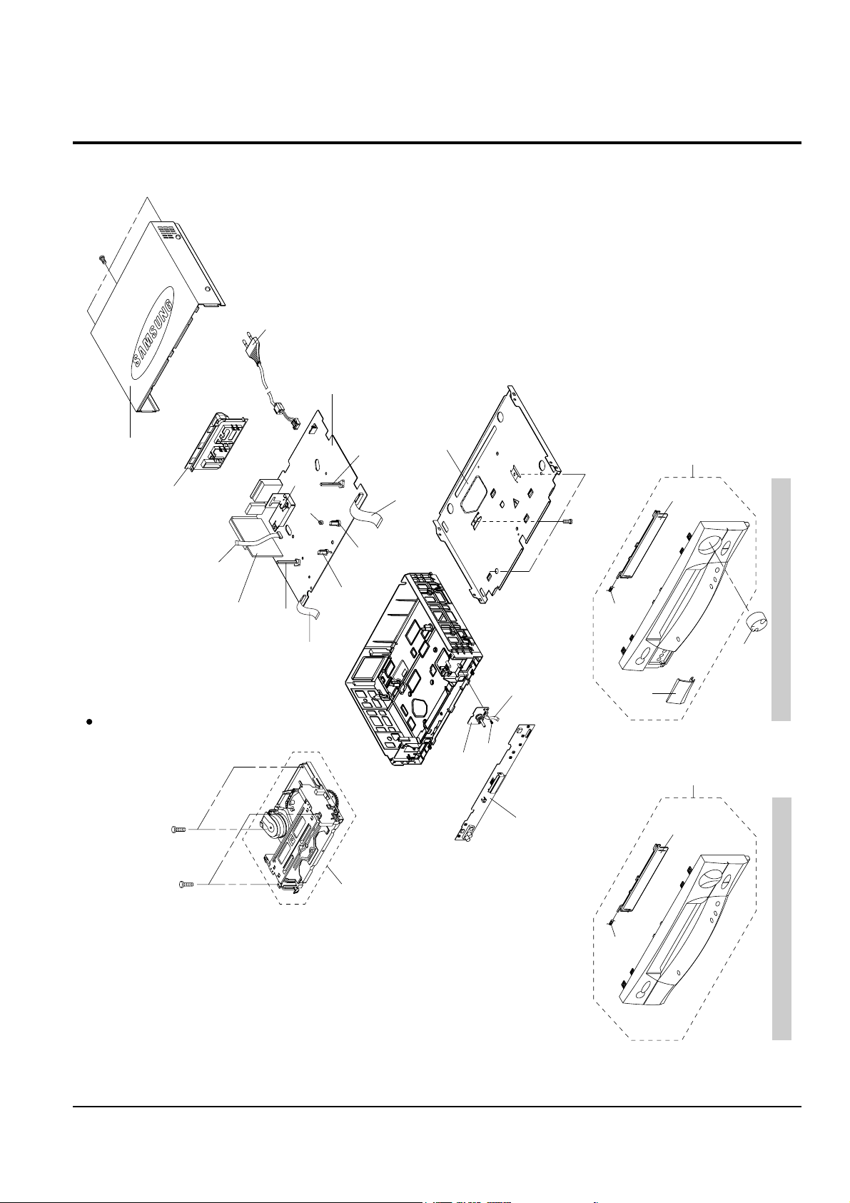
6-1 Cabinet Assembly
CN604A
157
153
157
155
661
108
SC301
MAIN PCB (S.N.A)
SP602
SP601
PT601A
PT602A
LD601A
FULL DECK (S.N.A)
SUB PCB
(S.N.A)
F/TIMER PCB
(S.N.A)
51
22
21
31
1
22
21
1
S.N.A : Service Not Available
SV-480G
SV-610X/210X/614B/210B/470G
109
(S.N.A)
157
CN77A
CN601A
CN605A
TOP CABINET (S.N.A)
Exploded View and Parts List
Samsung Electronics 6-3
Loc. No Par t No Description and Specification Remark
1
Refer to table below
ASSY-PANEL FRONT
21
Refer to table below
DOOR-CASSETTE
22 AC61-62003A SPRING;-,SUS304,(GE/RCA),-,-,-,31 AC64-50959M DOOR-FRONT SV-480G ONLY
51 AC64-10973A KNOB-SHUTTLE;ABS94,HB,GRY SV-480G ONLY
108
Refer to table below
CONNECTOR BOARD-ASSY
109 AC63-32127A COVER-BOTTOM;SV-B80F,SECC,353.2X275,T0.5
153 AC60-12126A SCREW-BH;-,BH,-,4*12,FE,FZY,-,-,155 AC60-12134A SCREW-TAP BH;-,BH,-,2-4X16,-,FE
157 AC60-10063A SCREW-TAPTITE;BH,+,-,M3,L12,ZPC3,SWRCH18
661
Refer to table below
POWER-CORD
CN601A 3809-001090 CABLE-FLAT;30V,80C,100mm,22P,1.0MM, UL2896
CN604A 3809-001048 CABLE-FLAT;30V,80C,110mm,6P,1.25MM, UL2896
CN605A 3809-001049 CABLE-FLAT;30V,80C,100mm,5P,1.25MM, UL2896 SV-480G ONLY
CN77A 3809-001094 CABLE-FLAT;30V,80C,40mm,5P,1.25MM, UL2896 SV-480G ONLY
LD601A AC61-22345A HOLDER-LED;POM,-,-,-,-,PT601A AC61-22344A HOLDER-PHOTO;POM,-,-,-,-,PT602A AC61-22344A HOLDER-PHOTO;POM,-,-,-,-,SP601 AC61-22321A HOLDER-TR;POM,-,-,-,-,SP602 AC61-22321A HOLDER-TR;POM,-,-,-,-,SC301 AC98-12023J ASSY-SH/CASE TOP;SV-A140F,IS-PAL
COUNTRY MODELS 1 21 108 661
GERMANY SV-610X
AC98-11255S AC64-50958K AC61-11039J AC39-10019A
SV-210X
AC98-11255X AC64-50958J AC61-11039D AC39-10019A
U.K SV-614B
AC98-11256A AC64-50958D AC61-11039H AC39-12022K
SV-210B
AC98-11256E AC64-50958F AC61-11039D AC39-12022K
POLAND SV-480G
AC98-11255T AC64-50958H AC61-11039D AC39-10019A
SV-470G
AC98-11255W AC64-50958H AC61-11039D AC39-10019A
Exploded View and Parts List
6-4 Samsung Electronics
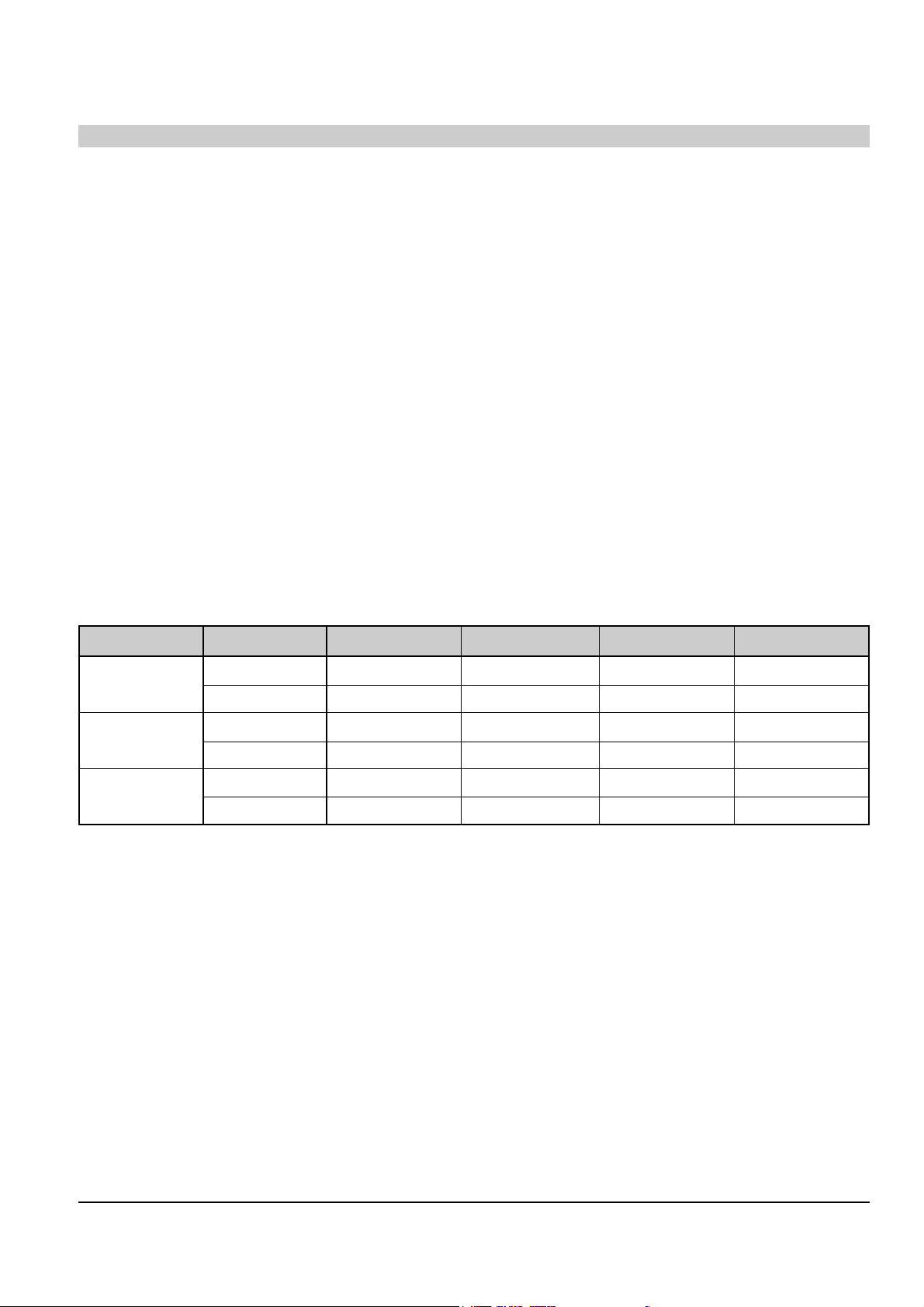
6-2 Mechanical Parts (Top Side)
T216
T201
T207
T300
901
920
901
T203
T209
T240
900
T239
T210
956
956
956
T208
T227
T233
957
T234
T228
T230
T229
T231
901
T233
T204
T238
T232
T225
T226
952
G
T236
T211
T223
T217
T219
952
T218
T220 T221
T222
G
G
O
G
919
T224
T212
<DX7-AC/DX8-AC ONLY>
<DX7-AC/DX8-AC
ONLY>
T202

Exploded View and Parts List
Samsung Electronics 6-5
Loc. No Par t No Description and Specification Remark
900 AC60-12091A SCREW-MACHINE;FP,BH,-,M3,L4,SWRCH10A,YEL ROB (OPTIONAL)
901 AC60-10012A SCREW-MACHINE;BH,+,M3,L8,-,FE,-,-,919 AC60-10004A SCREW-MACHINE;BH,+,M3,L8,ZPC,SWRCH18A,-,
920 AC60-10007A SCREW-TAPPING;BH,+,M2.6,L12,-,SWRCH18A,952 AC60-30018A WASHER-PLAIN;PLAIN,M3.2,D6,T0.5,POLYSLID
956 AC60-30007A WASHER-SLIT;PLAIN,ID2.5,OD7,T0.5,SPC1,-,
957 AC60-30008A WASHER-SLIT;-,ID3.5,OD9,T0.5,SPC1,-,T201 AC66-10023A REEL-DISK L ASSY;POM,-,PACKAGE,X-5,T202 AC66-10022A REEL-DISK R (ASSY);POM,-,PACKAGE,X-5,T203 AC66-30474A BRAKE-SUB L;-,PBT,-,-,-,X-5/IS
T204 AC66-30148A BRAKE SUB R;-,-,-,-,X5,T207 AC66-30475A BRAKE-MAIN L ASS’Y;-,POM+PELT,-,-,-,X-5/
T208 AC66-30476A BRAKE-MAIN R ASS’Y;-,POM+PELT,-,-,-,X-5/
T209 AC61-60112A SPRING- BRAKE MAIN;ES,SUS304WPB,PI0.35,I
T210 AC66-20073A GEAR RELAY S-ASSY;-,-,-,-,-,X5,T211 AC66-20037A GEAR- RELAY T;PEBAX7033,X-5,Z39,GEAR-SPU
T212 AC66-30073A ARM-TENSION ASSY;-,DX5-R,-,-,-,T216 AC61-60119A SPRING TENSION;ES,SWPB,PI0.4,D3,L33(OD3.
T217 AC66-30470A LEVER-REC S/W;-,PBT #3300,T4.0,L32,-,(XT218 AC61-62017A SPRING-SUB BRAKE L;ES,SUS304,PI0.23,D3.5
T219 AC33-10003P HEAD- MAGNET F/E;MH131S,-,-,-,L51.05XW7.
T220 AC66-82050A SLIDER-G/R ASSY(S);-,-,-,-,X-5
T221 AC66-82054A SLIDER-G/R ASSY(T);-,-,-,-,X-5
T222 AC33-10002E HEAD-CLEANER;-,-,-,X-5 (OPTIONAL)
T223 AC66-20065A RACK-HOUSING;L74.29,POM M90-44,BLK,M1,3.
T224 AC33-10216K HEAD-ACE ALL ASSY;-,-,-,-,X-7A
T225 AC66-80005A SLIDER-PINCH;POM(M90-44),T10.5,L54.35,NA
T226 AC66-30014A LEVER-REVIEW;ZYTEL(70G-43L),T5,-,PCD25.6
T227 AC66-30099A ARM-REVIEW ASSY;-,-,-,-,DX5-R,T228 AC66-30013A LEVER- CAM;PBT 6300T,-,L45,W9,X-5,T229 AC66-30003A LEVER-PINCH COMP;PBT 3300,T7.5,L45.25,-,
T230 AC61-60116A SPRING- PINCH COMP;TS,SWPB,PI1.0,D6,L38(
T231 AC67-32001A PRISM-LED;PMMA,D5,IF-850,-,-,T232 AC66-82049A SLIDER-PUSH;LUPOX 2150,T2,-,NTR,T233 AC61-62016A SPRING-SLIDE PUSH;ES,SUS304WPB,PI0.55,D3
T234 AC59-90402A UNIT-PINCH ROLLER;X-7A,RESIN BEARING
T236 AC66-10010A IDLER-ASSY;PACKAGE,-,X-5,T238 AC61-60132A SPRING ARM PINCH;CS,SUS304WPB,PI0.4,D7.1
T239 AC66-30132A LEVER JOG-ASS’Y;-,-,-,X-5 (OPTIONAL)
T240 AC61-60505A SPRING-REC S/W;-,ES,SUS304 WPB,PI0.29,PI
T300 AC96-10475L ASSY-CYLINDER;CX8A-H6P SV-610X/614B
AC96-10475G ASSY-CYLINDER;CX8A-D4P/DLC SV-480G/470G
AC96-10475D ASSY-CYLINDER;CX8A-S2P SV-210X
AC96-10480F ASSY-CYLINDER;CX8A-S2P(LP) SV-210B
 Loading...