

Samsung SUT-80, SUR-10 User Manual
ENGLISH
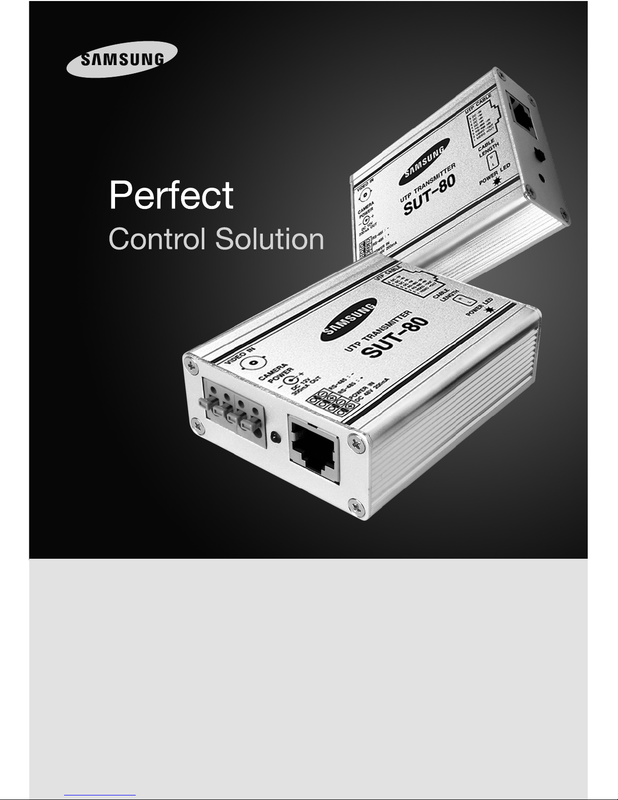
Thank you for choosing this Samsung UTP TRANSMITTER & RECEIVER product.
Before attempting to connect or operate this product, please read the instructions contained in this
manual carefully.
Please save this instruction manual for future reference.
UTP TRANSMITTER & RECEIVER SUT-80/SUR-10 USER’S MANUAL
UTP Transmitter & Receiver User's Manual
2
UTP Transmitter & Receiver User's Manual
3
Samsung Techwin cares for the environment at all product manufacturing
stages, and is taking measures to provide customers with more environmentally
friendly products.
The Eco mark represents Samsung Techwin’s devotion to creating
environmentally friendly products, and indicates that the product satisfies the EU
RoHS Directive.
Cautions/Warnings for Installation
Cautions/Warnings for Use
Table of Contents
1. Product Introduction ……………………………………………………… 4
1-1. Overview ……………………………………………………………… 4
1-2. Product Features ……………………………………………………… 4
2. Product Parts and Peripheral Device Connection …………………………… 5
2-1. Part Names and Functions …………………………………………… 5
2-1-1. SUT-80
2-1-2. SUR-10
2-2. Connecting UTP Cable ………………………………………………… 6
2-3. Peripheral Device Connection ………………………………………… 7
2-3-1. SUT-80, SUR-10 Configuration Example
2-3-2. SUT-80, SUJ-800 Configuration Example
3. Cautions/Warnings ………………………………………………………… 9
3-1. Cautions for Installation & Use ………………………………………… 9
3-2. Troubleshooting …………………………………………………………10
4. Specifications ……………………………………………………………… 11
5. Dimension ………………………………………………………………… 11
Before installing this product, please read the following cautions and warnings carefully.
Do not install the product in the following locations.
■
Places under extremely high or low temperature conditions
- Use this product under temperature conditions only between -15℃ and +40℃ to
prevent low performance and product malfunctions.
■
Places exposed to rain, snow, or high humidity
- Avoid water and moisture leakage into the product; it may cause the product to
malfunction.
■
Places containing or exposed to oil and gas
- Oil, moisture, and gas leakage into the product may cause product malfunctions.
■
Places exposed to vibration and shock
- Vibration and shock may cause product malfunctions.
■
Places under direct sunlight or exposed to outdoor weather conditions
- Direct sunlight and severe weather conditions may cause product malfunctions.
■
Places exposed to radio waves (RF) or near power cables
- Radio communication devices and electromagnetic waves from power lines may
cause product malfunctions.
■
Do not disassemble the product or insert foreign objects.
- Disassembly of the product or insertion of foreign objects such as metal may cause
break or damage the unit.
■
Make sure to turn off the product prior to installation.
- Before installing your product, please check its voltage rating and then turn on the
power.
■
Do not subject the product to physical shock or exert excessive force to operate the product.
- Shocks and excessive force on the components such as circuits may break or
seriously damage the unit.
UTP Transmitter & Receiver User's Manual
4
UTP Transmitter & Receiver User's Manual
5
1. Product Introduction
1-1. Overview 2-1. Part Names and Functions
1-2. Product Features
The UTP Video Transmitter & Receiver (SUT-80, SUR-10) converts the imbalance differential
signals of CCTV cameras to balanced differential signals and transmit them via twisted pair
cable (UTP, FTP, STP), enabling long-distance signaling without the interference of differential
noise. Our UTP video transmitter & receivers are also capable of supplying power to
connected cameras and transmitting camera control data using an extra cable.
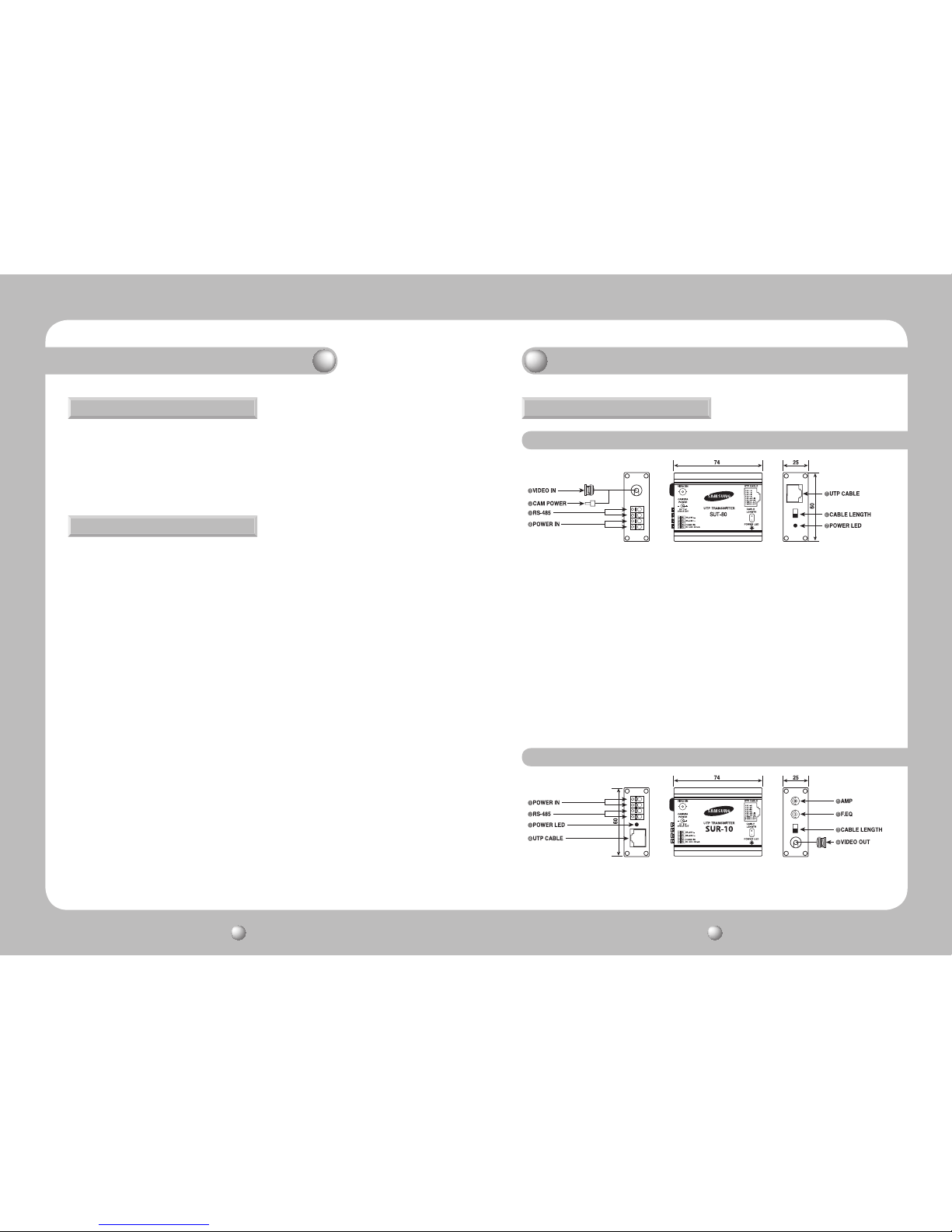
VIDEO IN : Connect the video output terminal of a camera.
CAM POWER : The power output terminal for a camera.
Do not connect a camera that uses a different power supply. (In case a
different power supply is used, please connect the enclosed load resistor.
)
RS-485 : RS-485 data terminal. Caution: Polarity sensitive.
POWER IN : Connect an extra adapter.
Do not use if the receiver and junction box are used for the supply power.
UTP CABLE : Connect a UTP cable attached with an RJ-45 plug.
CABLE LENGTH : Adjust the software according to the length of the UTP cable.
Max Distance Low (L): ~600m / (H): 600~2.4km
POWER LED : A red light turns on when the SUT-10 is powered on.
POWER IN : The adapter terminal.
· Provides differential signaling for video, power, and data transmission using 1 UTP cable
· Minimizes the interference of various transmission noises
· Provides BNC harness for the user’s convenience
· 2-level distance adjustment switch (Low: ~600m, High: 600~2.4km)
·
Max B/W via UTP cable: 2.4km, Max color: Differential video signaling up to 1.5Km when set to High)
· Provides AMP & F.EQ gain adjustments for optimal video quality
· Double duty power options: AC 24V 300mA & DC 12V 500mA (SUT-80: DC48V only)
· Convenient wiring options using RJ-45 Connector
·
Compatible with the older models of CVBS out cameras CVBS in DVRs, monitors, and dividers
· Compatible with most UTP cameras and DVRs
· Light, compact size perfectly fit into housings
· When used with the SUJ-800, supplies power to a connected camera within 1km
(Output current: DC 12V MAX 300mA; only DC-voltage cameras are compatible)
2. Product Parts and Peripheral Device Connection
2-1-1. SUT-80
2-1-2. SUR-10
 Loading...