

Samsung SHS-3420 User Manual
Please review all included documentation and use the product as intended. Safety precautions must be followed to
avoid personal injury or property damage.

2
Introduction & Helpful Tips • • • • • • • • • • • • • • • • • • • • • • • • • • • • • • • • • • • • • • • • • • • • • • • • • • • • • • • • • • • 2
Components & Tools
• • • • • • • • • • • • • • • • • • • • • • • • • • • • • • • • • • • • • • • • • • • • • • • • • • • • • • • • • • • • • • • 3
Door Preparation
• • • • • • • • • • • • • • • • • • • • • • • • • • • • • • • • • • • • • • • • • • • • • • • • • • • • • • • • • • • • • • • • • • 4
Installation
• • • • • • • • • • • • • • • • • • • • • • • • • • • • • • • • • • • • • • • • • • • • • • • • • • • • • • • • • • • • • • • • • • • • • • • 6
Basic Lock Operation Overview
• • • • • • • • • • • • • • • • • • • • • • • • • • • • • • • • • • • • • • • • • • • • • • • • • • • • • • • 8
Programming Features & Denitions
• • • • • • • • • • • • • • • • • • • • • • • • • • • • • • • • • • • • • • • • • • • • • • • • • 9-12
Programming
• • • • • • • • • • • • • • • • • • • • • • • • • • • • • • • • • • • • • • • • • • • • • • • • • • • • • • • • • • • • • • • • • • • • 13
Miscellaneous Information
• • • • • • • • • • • • • • • • • • • • • • • • • • • • • • • • • • • • • • • • • • • • • • • • • • • • • • • • • • 16
Troubleshooting
• • • • • • • • • • • • • • • • • • • • • • • • • • • • • • • • • • • • • • • • • • • • • • • • • • • • • • • • • • • • • • • • • • 17
Management Number Table
• • • • • • • • • • • • • • • • • • • • • • • • • • • • • • • • • • • • • • • • • • • • • • • • • • • • • • • • • 19
Product Specications
• • • • • • • • • • • • • • • • • • • • • • • • • • • • • • • • • • • • • • • • • • • • • • • • • • • • • • • • • • • • • 20
Warranty
• • • • • • • • • • • • • • • • • • • • • • • • • • • • • • • • • • • • • • • • • • • • • • • • • • • • • • • • • • • • • • • • • • • • • • • 21
Drilling Template
• • • • • • • • • • • • • • • • • • • • • • • • • • • • • • • • • • • • • • • • • • • • • • • • • • • • • • • • • • • • • • • • • • 23
|
Table of Contents
Congratulations on the purchase of your Samsung Touchpad Door Lock! Your lock has a touch sensitive
number display pad and optionally a 13.56MHz Card reader. Up to 70 users can be registered to gain access
with unique Codes or Access Cards (supports ISO14443A type).
The touchpad makes it convenient to enter the code and the Randomizer function helps prevent lockpicking
using ngerprint traces on the touchpad. Other convenient functions such as
Automatic Locking / S
ound
Setting / Out-of-Home Security, etc. provide advanced security and peace of mind.
You can unlock the door using video intercom’s monitor after connecting a Samsung video intercom.
(Refer to page 6 for connection diagram to a video intercom).
|
Helpful Tips
|
Introduction
Do not attempt to repair the product yourself.
Change your codes regularly to ensure the security of your codes.
Minimize the lock’s exposure to moisture including wet hands and direct contact with liquids.
Do not exert excessive force or use sharp instrument on the touchpad.
Insert the batteries according to correct polarity.
When the low-battery warning sounds, replace all batteries immediately.
Do not mix old batteries with new batteries.
Use soft, dry cloth to clean the lock and avoid cleaning with water, alcohol or other chemicals.
3
|
Components and Tools
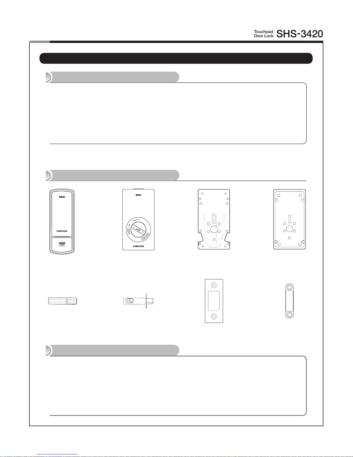
Components
● Exterior Unit
● Interior Unit
● Interior Mounting Plate
● Turn Shaft
● Strike
● 4 AA Alkaline Batteries
● Key Tag
● User Guide
● Screw Pack (6 types)
● Deadbolt
● Magnet
Tools
Door Preparation
● 2-1/8˝(54mm) hole saw
● 1˝(25mm) hole saw
● 3/8˝(10mm) drill bit
● 1/8˝(2.5mm) drill bit
● Chisel and hammer
Lock Installation
● Screw driver #2
● Drill
Parts Drawings
Exterior Unit Interior Unit Interior Plate Rubber Pad
Turn Shaft Deadbolt Strike Magnet
4
|
Door Preparation
Step 1. Check Door Status
1) This lock supports door thickness of 1-7/32˝ to 1-9/16˝ (31 to 40 mm).
2) Using the provided lock template, ensure that there are no obstructions that would prevent installing the
lock properly.
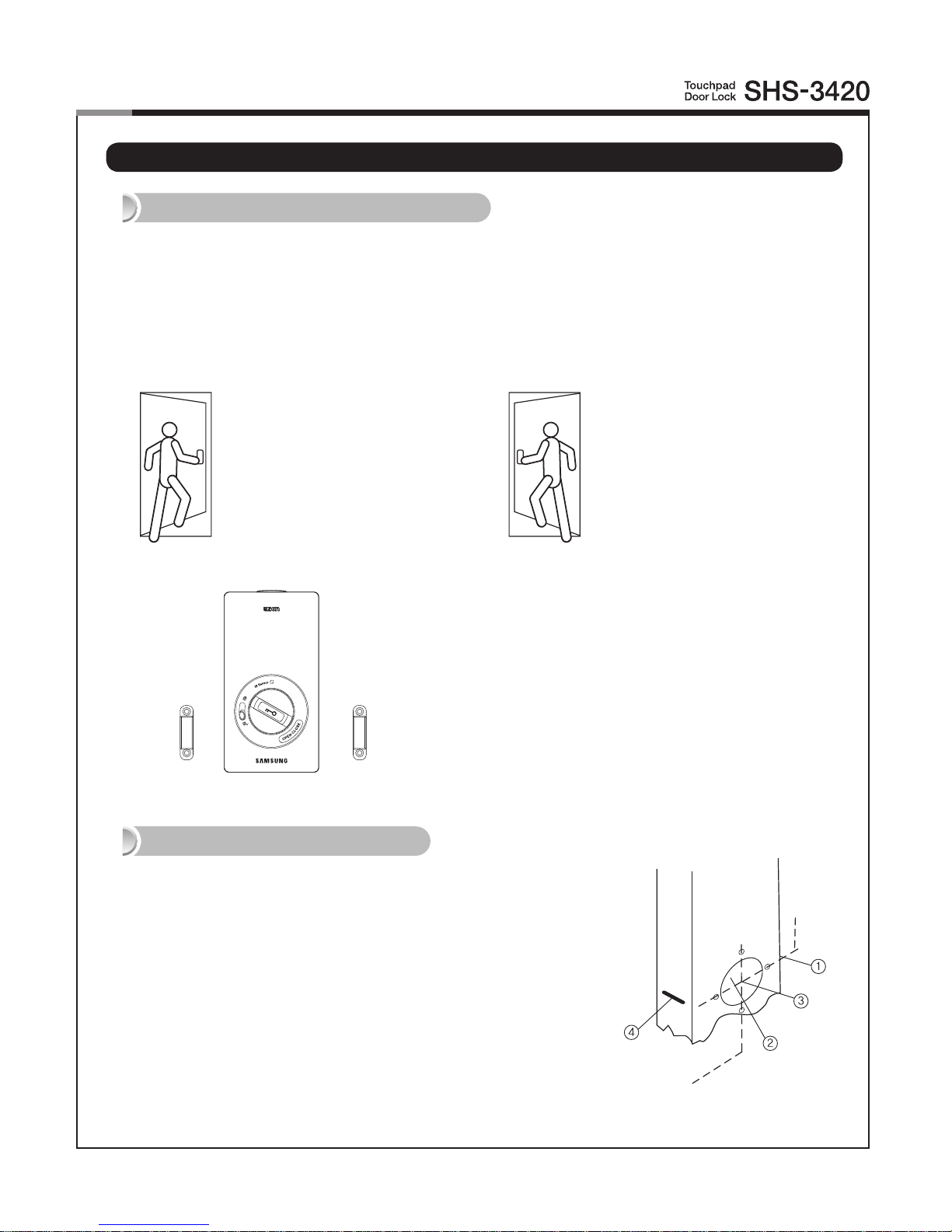
3) Take note of which orientation the deadbolt will need to be installed, left hand or right hand.
Left-Handed Door
When viewed from the Outside,
the hinge is on the left.
Right-Handed Door
When viewed from the Outside,
the hinge is on the right.
Step 2. Mark the Door
Check the location and direction of the deadbolt, attach the drilling
template (page 23) on the side of the door, and mark on it with a pen.
1) Align the horizontal line across the door.
2) Align the vertical line over the door.
3) Mark the centers of the holes with the drilling template.
4)
Mark the centerline of the deadbolt by aligning it with the vertical
line.
The hand type is not set by default and it is set
to the direction where the magnetic is detected.
In order to change the hand type when it is
already set, press the [OPEN/CLOSE] button
while the magnet is detected from the desired
direction.
5
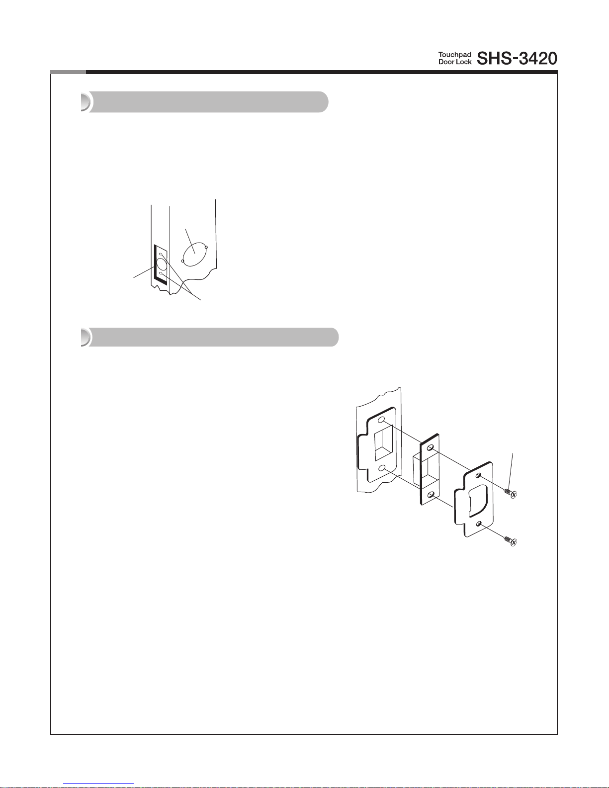
Step 3. Drilling
1) Drill a 2-1/8˝ (54 mm) diameter hole through the door, as indicated on
the template, using a hole saw.
2) Drill a 1˝ (25 mm) mortise hole using a hole saw.
3) Drill strike plate holes using a drill bit (1/8˝, 2.5 mm).
Step 4. Strike Plate Installation
FH+ T4 x 15
① 54mm
③ 2.5mm
② 25mm
1) Using the template, locate the center horizontal
line for the deadbolt hole, which lines up with the
center of the 2-1/8˝ hole, and draw a horizontal line
on the door frame to mark where you will make the
deadbolt mortise hole.
2) Measure half the thickness of the door. Now,
measure that distance from where the door stops
at the frame when the door is closed toward the
the door jamb and mark a straight, vertical line the
length of the door strike plate. Draw a horizontal
line from the mark you made in Step 1 toward the
vertical line. Where both lines cross, make a 1˝ (25
mm) diameter hole, 1/2˝ (13 mm) in depth.
3) Align the
holes of the strike plate with the vertical
line. Trace the outline of the strike plate and
mortise with a 1/16˝ (1.6 mm) indentation. Attach
the strike plate with the 2 screws provided.
(T4 x 15: for wooden door, U10-24 x 9: for metal
door)
6
Outside
|
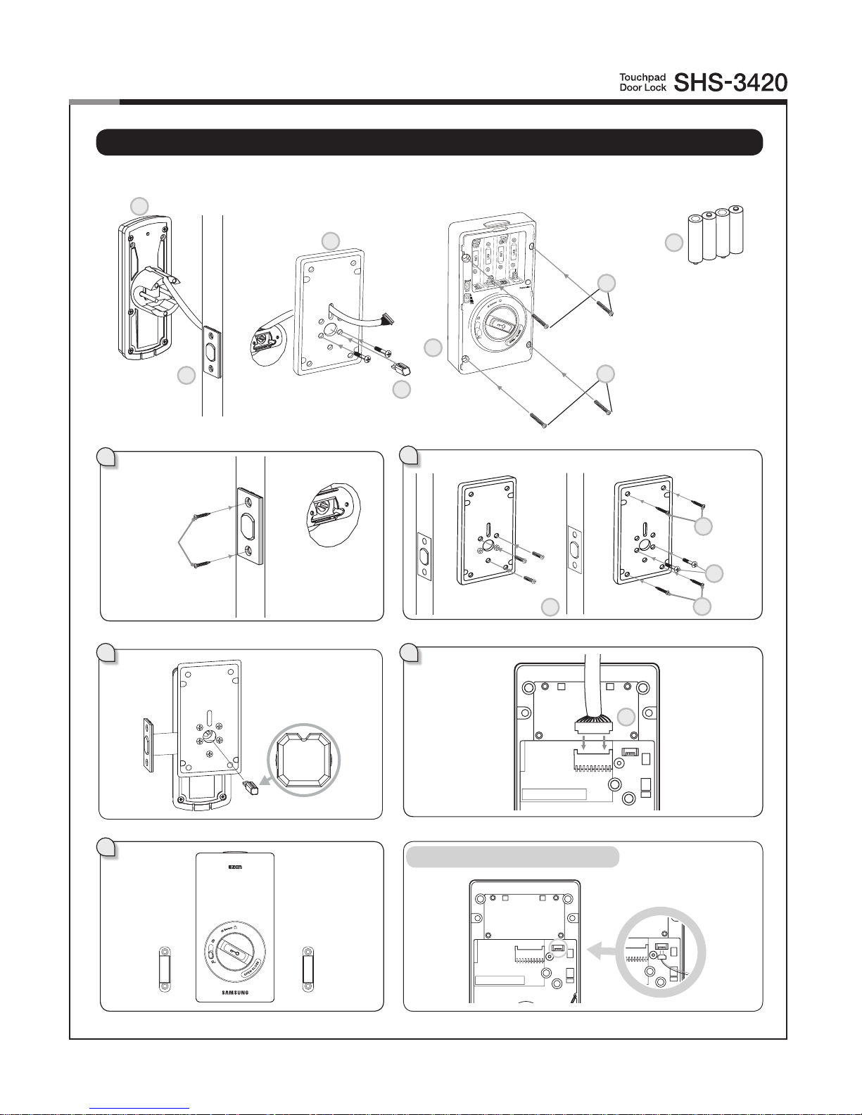
Installation
Inside
1
4 5
FH+ T4 x 25
Connection for video intercom
7
5
3
2
1
5
4
8
6b
PH+M4×26
3
FH+ M5 x 20
3b
FH+T4x25
OH+M4x22
FH+ T4 x 25
6a
PH+M4×26
3c
3a
3c

7
1. Insert the deadbolt.
1) Insert the deadbolt from the side of the door.
2) Rotate the deadbolt so the center hole is
horizontally aligned from the outside.
3) Fix
the deadbolt using two FH+T4 x 25 screws.
(T4x25/T4x15: for wooden door, U10-24x14: for
steel door)
2. Insert the Exterior Unit.
(Ensure the Exterior Unit is aligned with the
center hole of the deadbolt.)
3. Connect the Interior Mounting Plate.
1) Detach the Interior Mounting Plate from the
Interior Unit.
2) First, install the two OH+M4 x 22 screws (3a)
90% of the way
.
3) Next, fasten the Interior Mounting Plate with
three FH+M5 x 20 screws (3b).
4) Align the Exterior Unit with the Interior
Mounting Plate and then fasten the Interior
Mounting Plate using four FH+T4X25 screws
(3c).
5) T
ighten all screws on the Interior Mounting
Plate 100%.
4. While the deadbolt is in the open position,
insert the turn shaft.
5. Connect the cable to the Interior Unit.
6. Fix screws for the Interior Unit.
1) Align the Interior Unit on to the Interior
Mounting Plate, and check that the Manual
switchgear operates correctly. (Ensure cables
are arranged neatly to prevent them from
getting entangled or being compressed.)
2) Open the battery cover of the Interior Unit.
(There are screw grooves at the upper left and
right corners.)
3) Using two PH+M4 x 26 screws, fasten the
upper portion of the Interior Unit (6a).
4) Using two PH+M4 x 26 screws, fasten the
lower portion of the Interior Unit (6b).
7. Install the magnet after seeing page 23 to
26 for information about the drilling template sheet.
The
hand
type is not set by default and it
is set to the direction where the magnetic
is detected.
In order to change the hand type when it is
already set, press the [OPEN/CLOSE] button
while the magnet is detected from the desired
direction.
CAUTION: If the magnet is not detected,
automatic lock does not work.
So be sure to install it with the specied gap
size.
8. Install 4 Alkaline batteries.
A melody will sound when all 4 batteries are
installed correctly.
CAUTION: Press the [OPEN/CLOSE] button to
check whether the dead bolt works properly.
Connect the cable of video intercom to the
Interior Unit.
SHS-3420 is compatible with SHT-3005 and
other Samsung video intercom systems.
Procedures
Connect the video intercom

8
Touch the Card reader with
an Access Card.
Successful:
Ding dong dang dong
Failed:
Ding dong ding dong
Opening the Door with a PIN Code
The number pad will illuminate. (If the Random Secu-
rity function is enabled, press
the 2 illuminated numbers.)
The door opens within
one second.
Press the [Wake
Up] button.
Enter the PIN Code and
press the [ ] button.
Successful:
Ding dong dang dong
Failed:
Ding dong ding dong
Press the [Wake Up]
button.
The door opens within one
second.
|
Basic
Lock Operation Overview
Opening the Door with a Card
→
→
9
|
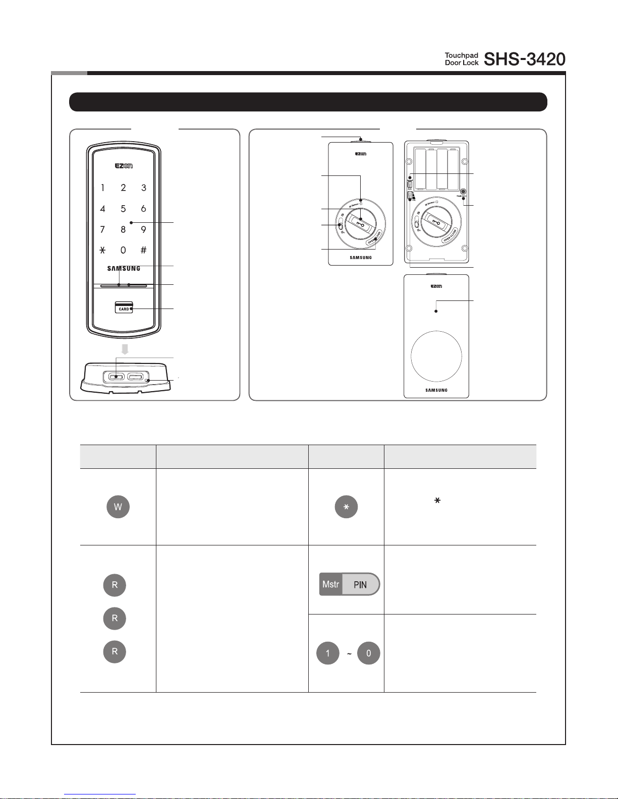
Programming Features
Number Pad
Display Lamp
Wake Up Button
Card Reader
External Power
Contact
Reset Button
Outside Inside
Symbols Description Symbols Description
Press the [Wake Up] button on
the Exterior Unit. It is used to
initiate Pin code or card access or
to quit the registration mode.
Press the [ ] button. It is used to
complete number entry.
5
10
Press the [Registration] button.
It is used to change the PIN Code
or set other functions.
R: Press the
[Registration]
button briey (~1 second)
R5: Press the
[Registration]
button for 5 seconds
R10: Press the
[Registration ]
button for 10 seconds
Enter the Master PIN Code (4~12
digits). Factory Default: 1234
Press the Number buttons.
Auto/Manual Switch
Registration Button
Volume Switch
Battery Cover
Battery Cover
Open Button
IR Sensor
Double Lock Lever
Open/Close Button
Manual Switchgear
Restart button
 Loading...